Cisco Catalyst 6500 Supervisor 2T Architecture - Ipland
Cisco Catalyst 6500 Supervisor 2T Architecture - Ipland
Cisco Catalyst 6500 Supervisor 2T Architecture - Ipland

Create successful ePaper yourself
Turn your PDF publications into a flip-book with our unique Google optimized e-Paper software.
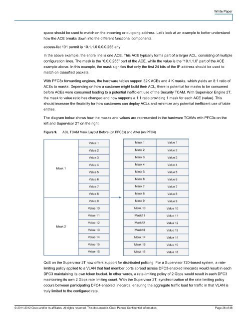
White Paperspace should be used to match on the incoming or outgoing address. Let’s look at an example to better understandhow the ACE breaks down into the different functional components.access-list 101 permit ip 10.1.1.0 0.0.0.255 anyIn the above example, the entire line is one ACE. This ACE typically forms part of a larger ACL, consisting of multipleconfiguration lines. The mask is the “0.0.0.255” part of the ACE, while the value is the “10.1.1.0” part of the ACEexample above. In this example, the mask signifies that only the first 24 bits of the IP address should be used tomatch on classified packets.With PFC3x forwarding engines, the hardware tables support 32K ACEs and 4 K masks, which yields an 8:1 ratio ofACEs to masks. Depending on how a customer might build their ACL, there is potential for masks to be consumedbefore ACEs were consumed leading to a potential inefficient use of the Security TCAM. With <strong>Supervisor</strong> Engine <strong>2T</strong>,the mask to value ratio has changed and now supports a 1:1 ratio providing 1 mask for each ACE (value). Thisshould increase the flexibility for how customers can deploy ACLs and minimize any potential inefficient use of tableentries.The diagram below shows how the masks and values are represented in the hardware TCAMs with PFC3x on theleft and <strong>Supervisor</strong> <strong>2T</strong> on the right.Figure 9.ACL TCAM Mask Layout Before (on PFC3x) and After (on PFC4)QoS on the <strong>Supervisor</strong> <strong>2T</strong> now offers support for distributed policing. For a <strong>Supervisor</strong> 720-based system, a ratelimitingpolicy applied to a VLAN that had member ports spread across DFC3-enabled linecards would result in eachDFC3 maintaining its own token bucket. In other words, a rate-limiting policy of 2 Gbps would result in each DFC3maintaining its own 2 Gbps rate limiting count. With the <strong>Supervisor</strong> <strong>2T</strong>, synchronization of the rate limiting policyoccurs between participating DFC4-enabled linecards, ensuring the aggregate traffic load for traffic in that VLAN istruly limited to the configured rate.© 2011-2012 <strong>Cisco</strong> and/or its affiliates. All rights reserved. This document is <strong>Cisco</strong> Partner Confidential Information. Page 26 of 46