Cisco Catalyst 6500 Supervisor 2T Architecture - Ipland
Cisco Catalyst 6500 Supervisor 2T Architecture - Ipland
Cisco Catalyst 6500 Supervisor 2T Architecture - Ipland

You also want an ePaper? Increase the reach of your titles
YUMPU automatically turns print PDFs into web optimized ePapers that Google loves.
<strong>Cisco</strong> <strong>Catalyst</strong> <strong>6500</strong> <strong>Supervisor</strong> <strong>2T</strong><strong>Architecture</strong>White PaperAuthor: Carl Solder – CCIE #2416Distinguished Technical Marketing EngineerCloud Switching Services Technology GroupReviews: Patrick Warichet – CCIE #14218Shawn WargoTechnical Marketing EngineersCloud Switching Services Technology Group
White PaperIntroductionThe <strong>Cisco</strong> <strong>Catalyst</strong> <strong>6500</strong> <strong>Supervisor</strong> Engine <strong>2T</strong> is the latest addition to the <strong>Catalyst</strong> <strong>6500</strong> family of Multi-LayerSwitching <strong>Supervisor</strong> Engines. It offers much higher levels of forwarding performance, increases the scalability ofmany previously supported features, and introduces a host of new hardware-enabled functions beyond all previous<strong>Catalyst</strong> <strong>6500</strong> <strong>Supervisor</strong> models.This white paper will provide an architectural overview of the new <strong>Supervisor</strong> <strong>2T</strong>. It will explore the physical layout ofthe <strong>Supervisor</strong> <strong>2T</strong>, provide details about its updated hardware components, and give an overview of its newlyintroduced features.High-Level Description of <strong>Supervisor</strong> <strong>2T</strong>The <strong>Supervisor</strong> <strong>2T</strong> is made up of four main physical components:● The baseboard● The 5th generation Multi-Layer Switching Feature Card (MSFC5)● The 4th generation Policy Feature Card (PFC4)● The 2 Tbps Switch FabricThe <strong>Supervisor</strong> baseboard forms the foundation upon which many of the purpose-built daughter cards and othercomponents are placed. It houses a multitude of application-specific integrated circuits (ASICs), including the ASICcomplex that makes up the primary two Terabit (2080 Gbps) crossbar switch fabric, as well as the port ASICs thatcontrol the front-panel 10 GE and GE ports.The MSFC5 is a daughter card that holds the CPU complex, which serves as the control plane for the switch. Thecontrol plane handles the processing of all software-related features. One major difference from earlier versions ofthe MSFC is that this version combines what were previously two separate CPU complexes into one. More details onthis new CPU complex will be explored later in this paper.The PFC4 is another daughter card that incorporates a special set of ASICs and memory blocks, which providehardware-accelerated data-plane services for packets traversing the switch. It introduces a number of scalabilityenhancements, by increasing the size of many of the memory tables used by many of the hardware-acceleratedfeatures. The PFC4 also introduces a number of new hardware-accelerated features, such as <strong>Cisco</strong> TrustSec (CTS)and Virtual Private LAN Service (VPLS).The 2 Tbps Switch Fabric provides 26 dedicated 20 Gbps or 40 Gbps channels to support the new 6513-E chassis(in addition to all existing E series chassis models). On the <strong>Supervisor</strong> 720, the switch fabric supported 18 fabricchannels, which were used to provide two fabric channels per slot on all slots (with the exception of the 6513chassis). With the new 6513-E chassis, the <strong>2T</strong> Switch Fabric is capable of supporting dual fabric channels for alllinecard slots (Slots 7 and 8 are reserved for the Active and Standby <strong>Supervisor</strong>s).© 2011-2012 <strong>Cisco</strong> and/or its affiliates. All rights reserved. This document is <strong>Cisco</strong> Partner Confidential Information. Page 3 of 46
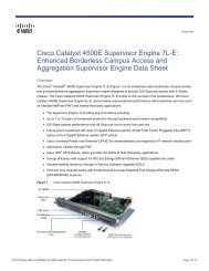
White PaperA high-level overview of the <strong>Supervisor</strong> <strong>2T</strong> board layout is shown in the diagram below.Figure 1.<strong>Supervisor</strong> <strong>2T</strong> Board LayoutA summary of the <strong>Supervisor</strong> <strong>2T</strong> critical features is listed in the table below:Table 1.Important Baseboard Features of <strong>Supervisor</strong> <strong>2T</strong>FeatureSwitch fabric typeForwarding engine daughter cardCPU daughter cardUplink portsUSB portsManagement PortsManagement LEDMedia slotForwarding performanceDescription2080 Gbps (2 Tbps) crossbar switch fabricPFC4 or PFC4XLMSFC52 x 10 GE (X2 optic support)3 x GE (SFP support)2 x USB (1 x Type-A and 1 x Type-B)Serial console port (RJ-45)Connectivity management processor Ethernet port (RJ-45)Blue beacon LEDCompact flash slot (Type II)Up to 60 Mpps for L2, IPv4, and MPLS trafficUp to 30 Mpps for IPv6 trafficThe following sections provide more details on each of the major components of the <strong>Supervisor</strong> <strong>2T</strong>.System Level RequirementsThe <strong>Supervisor</strong> <strong>2T</strong> is designed to operate in any E-Series <strong>6500</strong> chassis. The <strong>Supervisor</strong> <strong>2T</strong> will not be supported inany of the earlier non E-Series chassis. The table below provides an overview of the supported and non-supportedchassis for <strong>Supervisor</strong> <strong>2T</strong>.Table 2.Chassis Options for <strong>Supervisor</strong> <strong>2T</strong>Supported ChassisNon Supported Chassis6503-E, 6504-E, 6506-E, 6509-E, 6509-V-E, 6513-E 6503, 6506, 6509, 6509-NEB, 6509-NEB-A, 6513, 7603, 7603-S, 7604, 7606,7606-S, 7609, OSR-7609, 7609-S, 7613© 2011-2012 <strong>Cisco</strong> and/or its affiliates. All rights reserved. This document is <strong>Cisco</strong> Partner Confidential Information. Page 4 of 46
White PaperFor the E-Series chassis, a corresponding E-Series fan (or high-speed HS fan) for that chassis is required to support<strong>Supervisor</strong> <strong>2T</strong>. While the 2500 W power supply is the minimum-sized power supply that must be used for a 6, 9, and13-slot chassis supporting <strong>Supervisor</strong> <strong>2T</strong>, the current supported minimum shipping power supply is 3000 W.The 6503-E requires a 1400 W power supply and the 6504-E requires a 2700 W power supply, when a <strong>Supervisor</strong><strong>2T</strong> is used in each chassis. Either AC or DC power supply options can be used. The chassis types, as well ascorresponding fan and power supply options that can be used with a <strong>Supervisor</strong> <strong>2T</strong>, are detailed in the followingtable.Table 3.Supported Chassis, Fan and Power Supply for <strong>Supervisor</strong> <strong>2T</strong>Supported Chassis Supported Fan Supported Power Supply6503-E WS-C6503-E-FAN PWR-1400-AC6504-E FAN-MOD4-HS PWR-2700-AC/4PWR-2700-DC/46506-E WS-C6506-E-FAN WS-CAC-2500W (now End of Sale)WS-CDC-2500WWS-CAC-3000WWS-CAC-4000W-USWS-CAC-4000-INTPWR-4000-DCWS-CAC-6000WPWR-6000-DCWS-CAC-8700W6509-E WS-C6509-E-FAN WS-CAC-2500W (now End of Sale)WS-CDC-2500WWS-CAC-3000WWS-CAC-4000W-USWS-CAC-4000-INTPWR-4000-DCWS-CAC-6000WPWR-6000-DCWS-CAC-8700W6509-V-E WS-C6509-V-E-FAN WS-CAC-2500W (now End of Sale)WS-CDC-2500WWS-CAC-3000WWS-CAC-4000W-USWS-CAC-4000-INTPWR-4000-DCWS-CAC-6000WPWR-6000-DCWS-CAC-8700W6513-E WS-C6513-E-FAN WS-CDC-2500WWS-CAC-3000WWS-CAC-4000W-USWS-CAC-4000-INTPWR-4000-DCWS-CAC-6000WPWR-6000-DCWS-CAC-8700W© 2011-2012 <strong>Cisco</strong> and/or its affiliates. All rights reserved. This document is <strong>Cisco</strong> Partner Confidential Information. Page 5 of 46
White PaperThe installation of the <strong>Supervisor</strong> <strong>2T</strong> into a given chassis is always performed in specific slots. Keyed guide pins areused between the chassis and <strong>Supervisor</strong> connectors to manage this. Each chassis has two slots reserved for<strong>Supervisor</strong> use. These are called out in the following table.Table 4.Chassis <strong>Supervisor</strong> Slots6503-E 6504-E 6506-E 6509-E 6509-V-E 6513-ESlot 1 Sup or L/C Sup or L/C Linecard Linecard Linecard LinecardSlot 2 Sup or L/C Sup or L/C Linecard Linecard Linecard LinecardSlot 3 Linecard Linecard Linecard Linecard Linecard LinecardSlot 4 Linecard Linecard Linecard Linecard LinecardSlot 5 Sup or L/C Sup or L/C Sup or L/C LinecardSlot 6 Sup or L/C Sup or L/C Sup or L/C LinecardSlot 7 Linecard Linecard Sup OnlySlot 8 Linecard Linecard Sup OnlySlot 9 Linecard Linecard LinecardSlot 10Slot 11Slot 12Slot 13LinecardLinecardLinecardLinecardThe <strong>Supervisor</strong> <strong>2T</strong> provides backward compatibility with the existing WS-X6700 Series Linecards (with the exceptionof the WS-X6708-10G, which will be replaced by the new WS-X6908-10G, discussed later), as well as select WS-X6100 Series Linecards only. There is no support for the WS-X62xx, WS-X63xx, WS-X64xx, or WS-X65xxLinecards.Note: All WS-X67xx Linecards equipped with the Central Forwarding Card (CFC) are supported in a <strong>Supervisor</strong><strong>2T</strong> system, and will function in centralized CEF720 mode.There is no compatibility between the <strong>Supervisor</strong> <strong>2T</strong> and earlier generations of Distributed Forwarding Cards (DFCs),such as DFC, DFC2, or DFC3x. The DFC is used to accelerate forwarding performance for the system as a whole,and uses the same forwarding architecture that is found on the PFC. The PFC4 architecture introduces a number ofchanges that differentiate it significantly in operation from earlier PFC/DFC models.These changes require that only the DFC4 can interoperate with the PFC4. Any existing WS-X67xx Linecards thathave a DFC3x will have to be upgraded with the new DFC4. WS-X67xx Linecards with a DFC4 installed will functionin distributed dCEF720 mode.Note: Any newly purchased WS-X6700 Series Linecards that are shipped with a DFC4 or DFC4XL pre-installedhave been renamed as WS-X6800 Series Linecards, to clearly separate the performance differences.Note: Due to compatibility issues, the WS-X6708-10GE-3C/3CXL cannot be inserted in a <strong>Supervisor</strong> <strong>2T</strong> system,and must be upgraded to the new WS-X6908-10GE-<strong>2T</strong>/<strong>2T</strong>XL.© 2011-2012 <strong>Cisco</strong> and/or its affiliates. All rights reserved. This document is <strong>Cisco</strong> Partner Confidential Information. Page 6 of 46
White PaperThe <strong>Supervisor</strong> <strong>2T</strong> Linecard support also introduces the new WS-X6900 Series Linecards. These support dual 40Gbps fabric channel connections, and operate in distributed dCEF<strong>2T</strong> mode.To summarize, the following linecards are supported by <strong>Supervisor</strong> <strong>2T</strong>:Table 5.<strong>Supervisor</strong> <strong>2T</strong>-Compatible LinecardsLinecard Family Linecard Linecard Description6900 Series Linecards (dCEF<strong>2T</strong>)6800 Series Linecards (dCEF720)6700 Series Linecards (CEF720)6100 Series Linecards (Classic)WS-X6908-10G-<strong>2T</strong>WS-X6908-10G-<strong>2T</strong>XLWS-X6904-40G-<strong>2T</strong>WS-X6904-40G-<strong>2T</strong>XLWS-X6816-10T-<strong>2T</strong>WS-X6816-10T-<strong>2T</strong>XLWS-X6848-TX-<strong>2T</strong>WS-X6848-TX-<strong>2T</strong>XLWS-X6848-SFP-<strong>2T</strong>WS-X6848-SFP-<strong>2T</strong>XLWS-X6824-SFP-<strong>2T</strong>WS-X6824-SFP-<strong>2T</strong>XLWS-X6704-10 GEWS-X6748-GE-TXWS-X6748-SFPWS-X6724-SFPWS-X6148A-RJ-45WS-X6148A-45AFWS-X6148-FE-SFPWS-X6148A-GE-TXWS-X6148A-GE-45AFWS-X6148E-GE-AT8-port 10 GE (DFC4/DFC4XL)4-port 40 GE or 16-port 10 GE (DFC4/DFC4XL)16-port 10 G Base-T (DFC4/DFC4XL)48-port 10/100/1000 RJ-45 (DFC4/DFC4XL)48-port GE SFP (DFC4/DFC4XL)24-port GE SFP (DFC4/DFC4XL)4-port 10 GE (CFC or DFC4/DFC4XL)48-port 10/100/1000 (CFC or DFC4/DFC4XL)48-port GE SFP (CFC or DFC4/DFC4XL)24-port GE SFP (CFC or DFC4/DFC4XL)48-port 10/100/1000 RJ-45 (Upgradable to PoE802.3af)48-port 10/100 RJ-45 with PoE 802.3af48-port 100 BASE-X (SFP)48-port 10/100/1000 Ethernet RJ-4548-port 10/100/1000 Ethernet RJ-45 with PoE802.3af48-port 10/100/1000 RJ-45 with PoE 802.3afand PoE+ 802.3atNote: Any existing WS-X67xx Linecards can be upgraded by removing their existing CFC or DFC3x and replacingit with a new DFC4 or DFC4XL. They will then be operationally equivalent to the WS-X68xx linecards but willmaintain their WS-X67xx identification.© 2011-2012 <strong>Cisco</strong> and/or its affiliates. All rights reserved. This document is <strong>Cisco</strong> Partner Confidential Information. Page 7 of 46
White PaperTable 6.DFC4 Field Upgradable LinecardLinecardWS-X6716-10GEWS-X6716-10TWS-X6724-SFPWS-X6748-SFPWS-X6748-GE-TXWS-X6704-10GELinecard Description16-port 10 GE (DFC3/DFC3XL)16-port 10 G Base-T (DFC3/DFC3XL)24-port GE SFP (DFC3/DFC3XL or CFC)48-port GE SFP (DFC3/DFC3XL or CFC)48-port 10/100/1000 (DFC3/DFC3XL or CFC)4-port 10 GE (DFC3/DFC3XL or CFC)Applicable linecards (from the table above) utilizing a DFC3x will need to upgrade to a DFC4 in order to operate in a<strong>Supervisor</strong> <strong>2T</strong> chassis. This level of interoperability is summarized in the table below.Table 7.PFC/DFC Interoperability MatrixPFC3A PFC3B PFC3BXL PFC3C PFC3CXL PFC4 PFC4XLDFC3A√PFC3B operatesas PFC3APFC3BXLoperates asPFC3APFC3C operatesas PFC3APFC3CXLoperates asPFC3ANot compatibleNot compatibleDFC3BDFC3B operatesas DFC3A√PFC3BXLoperates asPFC3BPFC3C operatesas PFC3BPFC3CXLoperates asPFC3BNot compatibleNot compatibleDFC3BXLDFC3BXLoperates asDFC3ADFC3BXLoperates asDFC3B√DFC3BXLoperates asDFC3B andPFC3C operatesas PFC3BPFC3CXLoperates asPFC3BXLNot compatibleNot compatibleDFC3CDFC3C operatesas DFC3ADFC3C operatesas DFC3BPFC3BXLoperates asPFC3B andDFC3C operatesas DFC3B√PFC3CXLoperates asPFC3CNot compatibleNot compatibleDFC3CXLDFC3CXLoperates asDFC3ADFC3CXLoperates asDFC3BDFC3CXLoperates asDFC3BXLDFC3CXLoperates asDFC3C√Not compatibleNot compatibleDFC4 Not compatible Not compatible Not compatible Not compatible Not compatible√PFC4XLoperates asPFC4DFC4XL Not compatible Not compatible Not compatible Not compatible Not compatible DFC4XLoperates asDFC4√© 2011-2012 <strong>Cisco</strong> and/or its affiliates. All rights reserved. This document is <strong>Cisco</strong> Partner Confidential Information. Page 8 of 46
White Paper<strong>Supervisor</strong> <strong>Architecture</strong>The major processing blocks of the <strong>Supervisor</strong> <strong>2T</strong> include the crossbar switch fabric, the MSFC5, the PFC4, thefabric interface ASICs, and the bus and fabric replication ASICs. Each of these block elements and theirinterconnection can be seen in the following diagram.Figure 2.<strong>Supervisor</strong> <strong>2T</strong> High-Level Block DiagramTheory of OperationAll packet processing is performed in a specific sequence through the different ASIC blocks. A high-level packetwalk is provided for packets that ingress and egress the local ports on the <strong>Supervisor</strong> below.Ingress Packet Processing1. Packets arriving on either the 1 G or 10 G ports have preliminary checks performed on them (by the PHY), suchas cyclic redundancy checks (CRCs), before being forwarded to the <strong>Cisco</strong> TS ASIC.2. The CTS ASIC performs ingress 802.1ae decryption (if enabled) and extracts the Security Group Tag (SGT) forRoles-Based ACL (RBACL) processing (if enabled). If CTS is disabled, this ASIC is passive. The packet is thenforwarded to the port ASIC.3. The port ASIC will store the packet in its local packet buffer and then applies an internal packet header, whichcontains information about the source port, VLAN, and more.4. The packet is then forwarded to the fabric interface and replication ASIC, where information from the packetheader is forwarded to the PFC4 or DFC4 for forwarding lookup processing.5. The Layer 2 and Layer 3 processing is performed by the PFC4 (if a CFC is used, or local uplink ports) and theforwarding result of is sent back to fabric interface and replication ASIC.© 2011-2012 <strong>Cisco</strong> and/or its affiliates. All rights reserved. This document is <strong>Cisco</strong> Partner Confidential Information. Page 9 of 46
White Paper6. Additional lookups may be performed by the fabric interface and replication ASIC (if this packet needsreplication services, such as SPAN, multicast, and others).7. The packet is then forwarded to the egress port ASIC (if the destination is local), or to the switch fabric (if thedestination is a port on a remote fabric-capable linecard), or to the bus replication ASIC (if the packetdestination is a linecard with connectivity only to the bus).Egress Packet Processing (Packets Received from Crossbar)1. Packets are received from one of the switch fabric channels.2. The switch fabric sends the packet to the fabric replication ASIC.3. The fabric replication ASIC stores the packet and sends the packet header information to the PFC4 forforwarding lookup processing.4. The PFC4 performs the lookup and sends the results back to the fabric replication ASIC.5. The fabric replication ASIC performs an additional lookup, if replication services are required.6. The fabric replication ASIC then forwards the packet (and replicated packets, if applicable) to the port ASIC,which contains destination information from PFC4.7. The port ASIC stores the packet in the packet buffer and performs egress checks on the packet.8. The port ASIC performs the packet rewrite and then forwards the packet to the CTS ASIC.9. If CTS is enabled, the CTS ASIC performs 802.1ae encryption, and the packet is forwarded to the PhysicalLayer Protocol (PHY), to be transmitted onto the cable.Egress Packet Processing (Packets Received from Shared Bus)1. Packets are received from the bus and are placed on the local bus.2. The Bus Replication ASIC stores the packet and sends packet header information to the PFC4 for forwardinglookup processing.3. The PFC4 performs the lookup and sends the results back to the bus replication ASIC.4. The bus replication ASIC performs an additional lookup, if replication services are required.5. The bus replication ASIC forwards the packet (and replicated packets, if applicable) to the port ASIC, whichcontains destination information from PFC4.6. The port ASIC stores the packet in the packet buffer, and performs egress checks on the packet.7. The port ASIC performs the packet rewrite and forwards the packet to CTS ASIC.8. If CTS is enabled, the CTS ASIC performs 802.1ae encryption, and the packet is forwarded to the PHY, to betransmitted onto the cable.The following sections provide more detail for each processing block.The Fabric and Bus ConnectorThe <strong>Catalyst</strong> <strong>6500</strong> supports two different switch backplanes, the crossbar switch fabric (top left in the abovediagram), and bus backplanes (top right in the above diagram). The crossbar switch fabric is the high-capacitybackplane that is used by the CEF720 and CEF<strong>2T</strong> generation of linecards to optimize switching performance. Thisbackplane refers to the 2 Terabit backplane that is contained within the <strong>Supervisor</strong>’s name. A second backplane(referred to as the “bus” backplane) is also present to support WS-X61xx linecards, supported service modules, andlinecards that do not utilize a local DFC4 for forwarding.The crossbar switch fabric provides a set of fabric channels (or data paths) that are assigned to the slots in thechassis where linecards are inserted. This is referred to collectively as the crossbar switch backplane. This array of© 2011-2012 <strong>Cisco</strong> and/or its affiliates. All rights reserved. This document is <strong>Cisco</strong> Partner Confidential Information. Page 10 of 46
White Paperfabric channels provides an any-to-any (full-mesh) connection option for the attached linecard to forward data over adedicated path to any other linecard installed in the chassis.The bus backplane is a 16 Gbps (full duplex) shared data bus that is used to provide a connection between attached“classic” linecards. The data bus operates at 62.5 Mhz and is 256 bits wide. The bridge ASIC provides the interfacethrough which those classic linecards can communicate with the PFC4 and MSFC5 for data processing services.Crossbar Switch FabricThe crossbar switch fabric on the <strong>Supervisor</strong> <strong>2T</strong> provides 2080 Gbps of switching capacity. This capacity is based onthe use of 26 fabric channels that are used to provision data paths to each slot in the chassis. Each fabric channelcan operate at either 40 Gbps or 20 Gbps, depending on the inserted linecard. The capacity of the switch fabric iscalculated as follows:26 x 40 Gbps = 1040 Gbps1040 Gbps x 2 (full duplex) = 2080 GbpsThe 2080 Gbps number is a marketing number (common among all switch vendors) and is used in all literature todenote that full duplex transmission allows data traffic to be transmitted and received simultaneously. While theswitch fabric capacity is documented as a full duplex number, note that the per-slot capacity of the E-Series chassisis NOT a full duplex number.The 80 Gbps per slot nomenclature represents 2 x 40 Gbps fabric channels that are assigned to each slot providingfor 80 Gbps per slot in total. If marketing math were used for this per slot capacity, one could argue that the E-Serieschassis provides 160 Gbps per slot.Figure 3. Fabric Channel Layout in 6509-EFor every chassis (except the 6513-E), there are enough fabric channels to provide dual fabric channels to eachlinecard slot, including the two <strong>Supervisor</strong> slots. The exception is the 6513-E. For the 6513-E chassis, there are dualfabric channels provided for Slots 1 through 6 and for Slots 9 through 13. Slots 7 and 8 are designated <strong>Supervisor</strong>onlyslots. If a linecard is inserted in either of these <strong>Supervisor</strong>-only slots, it will not be powered up.© 2011-2012 <strong>Cisco</strong> and/or its affiliates. All rights reserved. This document is <strong>Cisco</strong> Partner Confidential Information. Page 11 of 46
White PaperFigure 4. Fabric Channel Layout in 6513-EFabric Replication ASICThis ASIC is used to provide a number of important functions. First and foremost, it receives packets from the frontpanel GE and 10GE ports, extrapolates valuable information from packet headers, and forwards this information tothe PFC4 for packet lookup and associated forwarding services processing (Security, Quality of Service, NetFlow,and others). When packets return from packet lookup processing, this ASIC will perform packet rewrites according tothe lookup result.Another important processing role performed by this ASIC is multicast replication. This includes IGMP snooping forLayer 2 packets, as well as multicast expansion for Layer 3 multicast packets. Additionally, other replication servicesare supported to provision switched port analyser (SPAN, ER-SPAN, and more) capabilities.New capabilities also include support for <strong>Cisco</strong> TrustSec (CTS) and Virtual Switch Link (VSL). Given that, the frontpanel 10 GE ports can be used to become part of a VSL that facilitates the creation of a Virtual Switching System(VSS) domain.Port ASICThere are two port ASICs on the <strong>Supervisor</strong> used to provision the front panel 2 x 10GE and 3 x 1 GE ports. One portASIC supports a single 10 GE port and a single GE port. The other port ASIC supports a single 10 GE port and twoGE ports. The following list defines this port ASIC’s capabilities:● Per-port VLAN translation● VSL support (10 GE ports only)● <strong>Cisco</strong> TrustSec support (802.1ae link layer encryption)● Jumbo frames (up to 9216 bytes)● Flow control● 1P3Q4T (one strict priority queue, three normal round robin queues, and four Weighted Random EarlyDetection [WRED] thresholds per normal queue) queue structure for GE ports (this is the TX queue structure)● 1P7Q4T (one strict priority queue, seven normal round robin queues, and four WRED thresholds per normalqueue) queue structure for 10 GE ports (this is the TX queue structure)● 1Q8T (one normal round robin queues and eight WRED thresholds for that queue) queue structure for 1 GEports (this is the RX queue structure)● 2Q4T (two normal round robin queues and four WRED thresholds per normal queue) queue structure for 10GE ports (this is the RX queue structure)● 256 MB total queue buffer (split among the front panel 10 G and 1 G ports)● DWRR, WRR, and SRR scheduling schemes● WRED and Tail Drop congestion management© 2011-2012 <strong>Cisco</strong> and/or its affiliates. All rights reserved. This document is <strong>Cisco</strong> Partner Confidential Information. Page 12 of 46
White Paper● 802.1Q VLAN encapsulation● ECC protectionBridge ASICThe bridge ASIC primarily serves as the gateway for linecards using the bus to connect to the control plane and dataplane (MSFC5 and PFC4 respectively). It provides a connection into the bus backplane and receives packets fromlinecards, which it will forward to the MSFC5 or PFC4 for processing. It provides a packet buffer, as well as flowcontrol to manage data flows from the linecards. Once packet processing is complete for the packet, the bridge ASICwill send the results of the forwarding operation back over the bus to the classic linecards.MSFC5/PFC4Both of these will be discussed individually in more detail later in this paper.MSFC5The MSFC5 is a next-generation CPU daughter card for the <strong>Supervisor</strong> <strong>2T</strong>. It is not an optional daughter card andwill be present on every <strong>Supervisor</strong> <strong>2T</strong>. The MSFC5 cannot be installed on any other <strong>Supervisor</strong> 32 or <strong>Supervisor</strong>720, and is designed for the exclusive use on the <strong>Supervisor</strong> <strong>2T</strong>.The MSFC5 performs control plane services for the switch. Control plane functions typically process all thosefeatures and other processes that are not handled directly in hardware by purpose built ASICs. The MSFC5 CPUhandles Layer 2 and Layer 3 control plane processes, such as the routing protocols, management protocols likeSNMP and SYSLOG, and Layer 2 protocols (such as Spanning Tree, <strong>Cisco</strong> Discovery Protocol, and others), theswitch console, and more.Figure 5.MSFC5 on <strong>Supervisor</strong> <strong>2T</strong>On previous generations of the MSFC, there were two main CPU complexes that resided on the MSFC. These CPUcomplexes were known as the Route Processor (RP) and Switch Processor (SP) complex. The RP complex wasresponsible for performing Layer 3 control plane services, IOS configuration and associated management of theconfiguration, Address Resolution Protocol (ARP) processing, Internet Control Message Protocol (ICMP) processingand more.© 2011-2012 <strong>Cisco</strong> and/or its affiliates. All rights reserved. This document is <strong>Cisco</strong> Partner Confidential Information. Page 13 of 46
White PaperIts other main function was to create the CEF forwarding tables that are programmed into the PFC hardware memorytables (through the SP). The SP complex was responsible for performing Layer 2 control plane services, managingsystem power as well as programming various hardware elements in the switch. The IOS image that ran on theseprevious MSFCs, while downloaded from http://www.cisco.com as one binary image file, was in fact two discreteimages: one that ran on the RP CPU complex and one that ran on the SP CPU complex.The most important enhancement of the MSFC5 is the move from the dual CPU complex (RP/SP) to a single CPUcomplex that combines the RP and SP complexes into one. As such, this also introduces a new IOS image for the<strong>Supervisor</strong> <strong>2T</strong> that combines the previous two running images into one.Another valuable enhancement of this new MSFC5 is the introduction of a Connectivity Management Processor(CMP). The CMP is a stand-alone CPU that the administrator can use to perform a variety of remote managementservices. Examples of how the CMP can be used include:● System recovery of the control plane● System resets and reboots● The copying of IOS image files should the primary IOS image be corrupted or deletedThe CMP and the RP share the same console through a programmable multiplexor. By default, the firmwareprograms the multiplexor so the RP console is active on the front panel. The multiplexor intercepts specific escapesequences that instruct it to switch from one console to the other.If the sequence (Ctrl-C, Shift-M) is used three consecutive times, the multiplexor will switch the console to the CMP.If the sequence (Ctrl-R, Shift-M) is used three consecutive times, the multiplexor will switch back to the RP console.External IP connectivity to the CMP is provided by a new 10/100/1000 RJ-45 management interface on the frontpanel. This port can then be configured with an IP address, gateway, and connection method (for example, Telnetand SSH). The user can then access and control the system remotely, even if the RP is currently down.The specifications for the MSFC5 CPU complex as compared to the MSFC3 (<strong>Supervisor</strong> 720) are shown in thefollowing table:Table 8.MSFC5 vs. MSFC3Feature MSFC3 (<strong>Supervisor</strong> 720-10G) MSFC5 (<strong>Supervisor</strong> <strong>2T</strong>)CP CPU speedSP CPU - 600 MhzRP CPU - 600 MhzDual core with each core @ 1.5 GhzNumber CPU cores 1 2Connectivity Management Processor (CMP)CPUNo CMPSingle core @ 266 Mhz32 MB boot flash256 MB system memoryNVRAM 2 MB 4 MBOBFL flash N/A 4 MBBoot diskSP CPU - 1 GBRP CPU - 64 MBCF based - 1 GBCF card on <strong>Supervisor</strong> front panel Yes - 1 CF Slot Yes - 1 CF SlotDRAMSP - Up to 1 GBRP - Up to 1 GB2 GB (non-XL)4 GB (XL)© 2011-2012 <strong>Cisco</strong> and/or its affiliates. All rights reserved. This document is <strong>Cisco</strong> Partner Confidential Information. Page 14 of 46
White PaperThe MSFC5 uses DDR-II memory for improved speed of access. Two memory sockets are present on the board andare currently loaded with a single 2 GB DIMM for the non-XL version and two 2 GB DIMM for the XL version of the<strong>Supervisor</strong> <strong>2T</strong>. An OBFL (On Board Failure Logging) flash is also present, providing 4 MB of memory for loggingtemperature readings and other diagnostic information. A battery-powered NVRAM memory block of 4 MB is alsopresent on the board, which stores the startup-config, VLAN database, and other information necessary to boot thesystem.The MSFC5 has two temperature sensors, each located on one side of the board. The right hand side sensor isdesignated the “inlet” sensor, while the sensor on the left of the board is designated the “outlet” sensor. Thesesensors provide information that is fed into the environmental subsystem, which uses this information to assesstemperature thresholds.The MSFC5 complex also supports an on-board Compact Flash (CF) Boot Disk, which supports a standard CFType-II disk, with disk densities of up to 8 GB. The default Boot Disk shipped with the MSFC5 is 1 GB. The CF BootDisk can be used as a storage space for IOS images and configuration files as well as other user files that theadministrator may wish to have stored local to the switch.Along with the Boot Disk, the MSFC5 also manages the <strong>Supervisor</strong> <strong>2T</strong> front panel CF (Compact Flash) slot. Like theBoot Disk, this CF slot supports CF Type-II disks with densities of up to 8 GB being supported. The external CF Slothas an LED visible from the front panel that indicates if the CF slot is in use.The CMP, as introduced above, is a new enhancement that makes its debut on the <strong>Supervisor</strong> <strong>2T</strong>. In many respects,it is a CPU complex within the larger MSFC5 CPU complex. As such, it has its own CPU and memory separate fromthat found on the MSFC5. The CMP supports a front panel 10/100/1000 management port. This port supports autonegotiation, detection and correction of pair swaps (MDI crossover), and support for jumbo frames up to 9216 bytesin size. It also uses a bi-color LED on the front panel port to show activity and link status. In addition to the frontpanel Ethernet port, the CMP also provides a direct interface to the front USB ports, allowing USB consoleconnection to the CMP.A detailed view of the MSFC5 board is shown below:Figure 6.MSFC5 Block Diagram© 2011-2012 <strong>Cisco</strong> and/or its affiliates. All rights reserved. This document is <strong>Cisco</strong> Partner Confidential Information. Page 15 of 46
White PaperPFC4 and DFC4The PFC4 provides hardware accelerated forwarding for packets traversing the switch. This includes forwarding forIPv4 unicast/multicast, IPv6 unicast/multicast, Multi-Protocol Label Switching (MPLS), and Layer 2 packets. Alongwith forwarding, the PFC4 is also responsible for processing a number of services that are handled during theforwarding lookup process. This includes, but is not limited to, the processing of security Access Control Lists(ACLs), applying rate limiting policies, quality of service classification and marking, NetFlow flow collection and flowstatistics creation, EtherChannel load balancing, packet rewrite lookup, and packet rewrite statistics collection.The DFC4 is a daughter card that is located on selected linecards. The DFC4 contains the same ASIC functionalblocks that are found on the PFC4. The main purpose of the DFC4 is to provide local forwarding services for thelinecard, offloading this function from the PFC4. Using DFC4s helps scale performance of the overall chassis.Without any DFC4s present in the chassis, the maximum performance of a chassis with <strong>Supervisor</strong> <strong>2T</strong> is 60 Mpps(for IPv4 forwarding). Each DFC4 adds an additional 60 Mpps of forwarding performance to the aggregate forwardingcapacity of the chassis. All of the information written about the PFC4 below equally applies (function, scalability, andperformance) to the DFC4.The PFC4 is located on the right-hand side of the <strong>Supervisor</strong> <strong>2T</strong> baseboard, as shown in the diagram below.Figure 7.Policy Feature Card 4 on the <strong>Supervisor</strong> <strong>2T</strong>The location of the DFC4 on a linecard is shown in the following diagram. In the photo below, the DFC4 is locatedunderneath a protective cover that protects the daughter card from getting damaged when the linecard is inserted orremoved from a chassis.© 2011-2012 <strong>Cisco</strong> and/or its affiliates. All rights reserved. This document is <strong>Cisco</strong> Partner Confidential Information. Page 16 of 46
White PaperFigure 8.DFC on the WS-X6908-10GE LinecardPFC4 and PFC4XL Feature ReviewThe PFC4 offers a number of enhancements and new capabilities over earlier generations of the PFC. Thesehardware feature capabilities are summarized in the following table.Table 9.New PFC4 EnhancementsFunctional AreaForwardingFeatureIncreased forwarding performance of up to 60 Mpps for L2, IPv4 and MPLS forwarding and up to 30 Mppsfor IPv6 forwardingImproved EtherChannel load balancing utilizing an 8-bit hashIncreased multicast routes to 256 KSupport for 16 K bridge domainsSupport for 128 K logical interfacesIncreased MAC address table to 128 KIGMPv3 snooping in hardwarePIM registers in hardwareIPv6 MLDv2 snooping in hardwareIPv6 in IPv6 tunnellingIPv6 in IPv4 tunnellingFull Pipe tunnel modeTunnel source address sharingNetwork Security<strong>Cisco</strong> TrustSec (CTS) with support for RBACL (note that 802.1ae link layer encryption is a function of theport ASIC and not the PFC4)Hardware control plane policing (including multicast CoPP) and an increase in the number of hardware ratelimitersShared ACL table (with QoS) now up to 256 K entriesL2+L3+L4 ACLs1:1 mask ratio with ACE valuesACL dry run and hitless commitClassify using more fields in IP headerSource MAC + IP BindingDrop on source MAC missPer protocol per dropIpv4 and IPv6 uRPF© 2011-2012 <strong>Cisco</strong> and/or its affiliates. All rights reserved. This document is <strong>Cisco</strong> Partner Confidential Information. Page 17 of 46
White PaperFunctional AreaFeatureUp to 16 path lookup for uRPFNetFlow ServicesEgress NetFlowIncreased NetFlow table size to 512 K (non XL) or 1 M (XL)Improved NetFlow hashFlexible NetFlow and NetFlow v9 support in hardwareHardware-sampled NetFlowQuality of Service (QoS)Per-port -per-VLAN policiesDistributed policing (up to 4 K policers)Increased scalability for aggregate policing (up to 16 K policers) and microflow policing (up to 128 policers)Increased number of flow masks to reduce feature incompatibilitiesEgress microflow policingIncrease in DSCP mutation mapsPacket or byte-based policingVirtualizationLayer 2 over GREMPLS aggregate labels increased up to 16 KNative H-VPLSMPLS over GRE16 K EoMPLS tunnelsThe following sections provide a brief overview of each of the enhancements noted in the above table, divided intoLayer 2 and Layer 3 functional groups.Layer 2 - Increased MAC Address SupportA 128 K MAC address table is standard on both models of the PFC4. The MAC address table has been enhanced tosupport additional fields in a MAC address table entry, such as the bridge domain (BD) that the MAC address is apart of.Layer 2 - Bridge DomainsThe bridge domain is a new concept that has been introduced with PFC4. A bridge domain is used to help scaletraditional VLANs, as well as to scale internal Layer 2 forwarding within the switch. Bridge domains are mapped toeach VLAN that a user configures, as well as other resources such as an EoMPLS/VPLS tunnel, L3 sub-interfaces,and multicast Egress replication-mode. In essence, a bridge domain is equal to a VLAN (which is a 12-bit ID,allowing 4096 unique values). Bridge domains use a 14 bit ID (12 bits are VLAN ID), for a total of 16 K bridgedomains supported in hardware by the PFC4.Layer 2 - Increased Logical interfacesThe PFC4 introduces the concept of a Logical Interface (LIF), which is a hardware-independent interface (or port)reference index associated with all frames entering the forwarding engine. A LIF is a 72-bit internal addresscomprised of the bridge domain (BD), the source port index and other associated information (for example, protocoltype) used by the PFC4 to facilitate forwarding decisions. This allows Layer 2 forwarding characteristics to belogically separated from Layer 3 characteristics. The PFC4 adds hardware support for up to 128 K LIFs.Layer 2 - Improved EtherChannel HashSkew tables have been introduced to overcome issues with distributing traffic over an odd number of links (3, 5, 6,and 7) that form part of an EtherChannel link bundle. Previous PFC3x engines offered balanced distribution acrosseven numbered link (2, 4, and 8) bundles. However, link bundles with 3, 5, 6, or 7 member ports could end up withuneven distribution. The use of skew tables, as part of the processing logic for selecting a link in a bundle, helpsalleviate those earlier problems.© 2011-2012 <strong>Cisco</strong> and/or its affiliates. All rights reserved. This document is <strong>Cisco</strong> Partner Confidential Information. Page 18 of 46
White PaperInputs (fields) used for the hash itself have also been extended. Options for including the input and output interfacesinto the hash, along with the VLAN ID, provide for more granular link selection. These options also help overcomeearlier issues with link selection for multicast traffic over VLAN trunks, where one link in the bundle could be favoredover others.Layer 2 - VSL SupportVSL is a technology that allows two physical <strong>Catalyst</strong> <strong>6500</strong> switches to operate together as a single logical unit. Inthis mode, the <strong>Supervisor</strong> Engine <strong>2T</strong> in one chassis is the SSO Active and the <strong>Supervisor</strong> Engine <strong>2T</strong> in the otherchassis is the SSO Standby. As with stand-alone (non-VSS) HA, the Active <strong>Supervisor</strong> is responsible for the controlplane. While only one of the two control planes is active in a virtual switch setup, both data planes are active. Havingboth data planes active allows the virtual switch system to optimize hardware forwarding and use both PFC4 enginesto perform hardware-enabled tasks for each chassis. Support for VSL is included with the PFC4 and mirrors thatfound in the previous PFC3C/PFC3C-XL <strong>Supervisor</strong> Engines 720.Layer 2 - Per Port-Per-VLANThis feature is designed for Metro Ethernet deployments where policies based on both per-port and per- VLAN needto be deployed. Typically these scenarios define a network deployment model where different VLANs carryingdifferent customer traffic is carried on the same physical interface. Earlier PFC engines only allowed port-based orVLAN-based polices to be applied to a port at any one time. A port-based policy would disregard VLAN information,and likewise a VLAN-based policy would disregard port information. Support for this new interface type in the PFC4allows per-port-per-VLAN policies to be applied where both the VLAN and port can be considered in the assignedpolicy.Layer 3 - Increased Layer 3 Forwarding PerformanceThe PFC4 forwarding engine now supports forwarding performances of up to 60 Mpps for both Layer 2 and IPv4Layer 3 forwarding. Technically, it is actually a 120 Mpps forwarding engine, but since each packet passes throughthe PFC4 twice (once for ingress processing and once for egress processing, which is discussed later), the effectiveforwarding performance equates to 60 Mpps.Due to the length of the address, IPv6 requires an additional internal cycle, which makes the effective IPv6forwarding performance 30 Mpps. Note that the PFC3B/XL forwarding engines supported forwarding performance upto 30 Mpps for IPv4 and 15 Mpps for IPv6, while the PFC3C/XL forwarding engines supported forwardingperformance up to 48 Mpps for IPv4 and 24 Mpps for IPv6.Layer 3 - uRPF for IPv6Unicast Reverse Path Forwarding (uRPF) is a tool that can be used to protect against address spoofing. The uRPFcheck performs a lookup into the FIB, using the source address as the lookup index (as opposed to the destinationaddress). The lookup is performed to determine if the packet arrived on an interface where the source address of thepacket matches the network found through that interface. If the packet had a source IP address of “A”, but it arrivedon an interface from where network “A” does not exist, then the packet is deemed to have been spoofed and will bedropped.The PFC4 extends support for uRPF to include IPv6, which was not available in the PFC3x. More importantly, PFC4now supports 16 prefixes during both an IPv4 and an IPv6 uRPF lookup compared to only supporting the lookup of 2prefixes with the PFC3x.Layer 3 - Tunnel Source Address SharingWith the PFC3x family, each tunnel was required to use a unique source IP address as the tunnel source. If two ormore tunnels were configured using the same source address, packets for the second and subsequent tunnelsconfigured would be switched in software. With the PFC4, this scenario has been enhanced and now multipletunnels can be configured to share the same source address, while the tunnelled packets are switched in hardware.© 2011-2012 <strong>Cisco</strong> and/or its affiliates. All rights reserved. This document is <strong>Cisco</strong> Partner Confidential Information. Page 19 of 46
White PaperLayer 3 - IPv6 TunnellingThe PFC3x did not support IPv6 tunnelling options where the outer header was an IPv6 header. This behavior haschanged with PFC4. The PFC4 now supports the following new IPv6 tunnelling options:● ISATAP (Intra-Site Automatic Tunnel Address Protocol): ISATAP tunnelling protocol allows IPv6 packetsto be globally routed through the IPv6 network, while also being automatically tunneled through IPv4 cloudslocally within a site. ISATAP tunnelling uses an address format with specially constructed 64-bit EUI-64interfaces ID. PFC4 fully supports ISATAP tunnels, whereas PFC3x offered only partial support.● IPv6 tunnel for GRE packets: PFC4 supports IPv6 GRE tunnelling mode, where both IPv4 and IPv6 packetscan be encapsulated in an IPv6 GRE header and tunnelled across an IPv6 network. The PFC3x had limitedsupport for this tunnelling mode. The PFC4 can support up to 256 IPv6 GRE tunnels.● IPv6 generic tunnelling: IPv6 packets can be encapsulated in an IPv6 or IPv4 header and tunnelled acrossthe IPv6 network. The PFC4 offers support for this mode and 256 tunnel source addresses are supported.The PFC3x family did not support this tunnelling option.Layer 3 - VPLSVirtual Private LAN Service (VPLS) allows for a Layer 3 MPLS network to appear to operate like a Layer 2 Ethernetbasednetwork. It effectively allows native Ethernet frames to be transported across an MPLS network providing anyto any connectivity, just as if it were on a normal Ethernet LAN. Previous PFC engines required an external WANcard, such as the OSM or SIP-400, to provide support for VPLS. With PFC4, VPLS is supported natively, and noexternal WAN cards are required for this support.Layer 3 - MPLS over GREThe PFC4 now supports the MPLS over GRE tunnelling option in hardware. This was not supported in previousPFC3x engines. This capability is important for those customers looking to join MPLS backbones over a common IPnetwork.Layer 3 - MPLS Tunnel ModesMPLS provides a number of options for controlling how the EXP (experimental bit) can be set. The EXP valueprovides a way for a priority value to be assigned to an MPLS packet. The EXP setting is three bits providing 23values (eight values). The mechanisms used to control the setting of the EXP bit are referred to as tunnel modes,and are defined in RFC3270. The three tunnel modes are called uniform, short pipe, and pipe tunnel modes.In uniform mode, any changes made to the EXP value of the topmost label on a label stack are propagated bothupward, as new labels are added, and downward, as labels are removed.In short pipe mode, the IP precedence bits in an IP packet are propagated upward into the label stack as labels areadded. When labels are swapped, the existing EXP value is kept. If the topmost EXP value is changed, this changeis propagated downward only within the label stack, not to the IP packet.Full pipe mode is just like short pipe mode, except the PHB (per-hop behavior) on the mpls2ip link is selected, basedon the removed EXP value rather than the recently exposed type of service value. The underlying type of service inthe IP header in the packet is not modified.Regarding current levels of support for MPLS tunnel modes, previous PFC3x forwarding engines supported shortpipe and uniform tunnel modes. The PFC4 now adds support for full pipe tunnel mode.Layer 3 - Increased Support for Ethernet over MPLS TunnelsEthernet over MPLS (EoMPLS) provides a mechanism for two disparate LAN networks to be joined over an MPLSnetwork, thus allowing Ethernet frames to traverse an MPLS cloud. The PFC3x supported a maximum of 4 K© 2011-2012 <strong>Cisco</strong> and/or its affiliates. All rights reserved. This document is <strong>Cisco</strong> Partner Confidential Information. Page 20 of 46
White PaperEoMPLS tunnels. The number of tunnels now supported with the PFC4 has been increased to 16 K tunnels inhardware.Layer 3 - MPLS Aggregate Label SupportThe number of MPLS aggregate labels supported on the PFC4 has been increased significantly over what wassupported on the PFC3x. Aggregate label support has been increased to 16 K, up from 512 on the previous PFC3xfamily.Layer 3 - Layer 2 Over GREThe PFC4 family adds support for transporting Layer 2 packets over a generic route encapsulation (GRE) tunnel.This is a new capability added into the PFC4 hardware.Layer 3 - Increased Multicast RoutesThe PFC3x supported a maximum of 32 K multicast routes in hardware. The number of multicast routes that issupported in the PFC4 has been increased to 256 K. Note that the initial release will limit the maximum multicastroutes to 128 K for IPv4 and 128 K for IPv6.Layer 3 - PIM Register Encapsulation/De-Encapsulation for IPv4 and IPv6PIM (Protocol Independent Multicast) is used to build a forwarding path through a network for multicast packets. Aspart of the process that PIM uses to build this forwarding path, multicast routers and switches will send PIM registerpackets to a device called the rendezvous point (RP). When these PIM register packets are sent, they areencapsulated in an IPv4 unicast header. If a <strong>Catalyst</strong> <strong>6500</strong> is configured as a PIM rendezvous point (RP), then theprocessing of these PIM register packets requires the packets to be de-encapsulated in software.The PFC4 now supports the ability to both encapsulate and deencapsulate these PIM register packets in hardware,thus avoiding the performance penalty previously incurred on the <strong>Supervisor</strong> in processing these packets.Layer 3 - IGMPv3/MLDv2 SnoopingIGMP is a multicast protocol that allows a host to indicate to the network that they wish to receive a multicast stream.The network uses this information to build a multicast topology over which multicast packets can be efficientlyforwarded to hosts. IGMPv3 is the latest version of IGMP that allows hosts to specify a list of sources they wouldreceive traffic from enabling the network to drop packets from unwanted sources.Earlier PFC3x engines support hardware-based IGMP Layer 2 snooping for v1 and v2. IGMPv3 source-specificsnooping used a combined software and hardware model, where software is used to track specific sources, which isthen tied to a non source-specific hardware entry. The PFC4 now adds hardware-based snooping support for IGMPv3.MLDv2 snooping is Layer 2 snooping for IPv6 multicast packets. The PFC4 supports hardware-based MLDv2snooping for IPv6 hosts as well as IGMPv3 snooping for IPv4 hosts.Layer 3 - Increased Support for NetFlow EntriesUp to 512 K NetFlow entries can now be stored in the PFC4, and up to 1 M NetFlow entries (512 K for ingressNetFlow and 512 K for egress NetFlow) can now be stored in PFC4XL. This is quadruple the number of entriesoffered on the comparable PFC3x forwarding engines.Layer 3 - Improved NetFlow HashThe NetFlow implementation on all PFC forwarding engines uses a hash to both store and retrieve entries in theNetFlow table. With each generation of PFC engine, the efficiency of the hash has improved, allowing a greaterpercentage of the NetFlow table to be utilized. With PFC2 and PFC3a, the hash efficiency was 50 percent. Withsubsequent PFC3x, it improved to 90 percent. With PFC4, the hash has been improved yet again to provide a hashefficiency of close to 99 percent.© 2011-2012 <strong>Cisco</strong> and/or its affiliates. All rights reserved. This document is <strong>Cisco</strong> Partner Confidential Information. Page 21 of 46
White PaperLayer 3 - Egress NetFlowPreviously, NetFlow was only supported for ingress data traffic. Egress NetFlow provides support for collecting flowstatistics for packets after they have had ingress processing applied to them, and prior to transmission out theegress interface or interfaces. This can be of value, especially for users wanting to collect flow statistics for datamoving into and out of a VPN, for example.Layer 3 - Sampled NetFlowSampled NetFlow is a new feature in the PFC4 that allows customers to opt for NetFlow records to be created basedon a sample of the traffic matching the flow. Sample Netflow uses a 1/N based sampling which inspects one packetevery N packets. The PFC3x was capable of performing sampling but the operation was performed after theinspection process. The PFC4 performs the sampling during the inspection process, effectively reducing the amountof NetFlow entries. There are 1 K global NetFlow samplers supported in PFC4.Layer 3 - MPLS NetFlowThe PFC4 provides support for aggregate label at the Provider Edge (PE). This feature allows the inspection of IPtraffic belonging to a particular VPN before it is added with a MPLS label (ip2mpls) and after the last label is removed(mpls2ip). The MPLS NetFlow also allows the inspection of the IP header for non aggregate label at a P device(mpls2mpls).Layer 3 - Layer 2 NetflowThe layer 2 Netflow feature in the PFC4 allows Netflow lookups for IPv4, IPv6 and MPLS based packets to beperformed using the Layer 2 header.Layer 3 - Flexible NetFlowThe PFC4 now supports Flexible NetFlow (FnF), based on the NetFlow v9 record format. FnF allows users moreflexibility in defining which record types they want to use for a v9 record. More importantly, FnF now also includes anumber of new field options to allow for collection of MPLS, IPv6, and multicast information in a NetFlow record.Layer 3 - Distributed PolicingIn a PFC3x-based system using DFC3s, an aggregate policer applied on a VLAN that included ports on differentDFC3-enabled linecards could not synchronize their token buckets. As such, each DFC3-enabled linecard wouldmaintain its own aggregate policed count, resulting in the true aggregate rate being multiplied by the number ofDFC3s which apply the policer.PFC4 solves this problem with the introduction of the distributed policer. This allows the policing state to besynchronized across multiple DFC4-enabled linecards providing for multi-port multi-module policing. A total of 1 Kdistributed policers are supported with PFC4.Layer 3 - DSCP MutationQuality of Service (QoS) support in PFC4 is enhanced with its support for multiple ingress and egress DifferentiatedServices Code Point (DSCP) mutation maps. A DSCP mutation map is a table that defines to what an existing DSCPvalue in a packet can be modified. DSCP mutation maps facilitate the marking (or reprioritizing of packets) process.Up to 14 ingress DSCP mutation maps and up to 16 egress DSCP mutation maps can be defined in the PFC4.Layer 3 - Aggregate PolicersAn aggregate policer is a rate limiting policy that can be applied to a port, group of ports, VLAN or group of VLANsthat limits total traffic through those ports/VLANs to a predetermined bandwidth amount. Traffic in excess of the limitcan either be marked down and forwarded, or dropped. The previous PFC3x forwarding engine supported amaximum of 1023 aggregate policers per chassis. PFC4 increases the limit on aggregate policers supported to 6 K.© 2011-2012 <strong>Cisco</strong> and/or its affiliates. All rights reserved. This document is <strong>Cisco</strong> Partner Confidential Information. Page 22 of 46
White PaperLayer 3 - Microflow PolicersLike an aggregate policer, a microflow policer is a rate-limiting policy that can be applied to a port, group of ports,VLAN, or group of VLANs that limits total traffic for each flow through those ports or VLANs to a stated bandwidthamount. Traffic in excess of the limit can either be marked down and forwarded, or dropped. The previous PFC3xforwarding engine supported a maximum of 63 microflow policers per chassis. PFC4 increases the limit on microflowpolicers supported to 127.Another enhancement to microflow policing is that with PFC4, a microflow policer can now be configured for bothingress and egress. Previously, a microflow policer could only be configured for the ingress direction.Layer 3 - Policing by Packets or BytesThe PFC4 now introduces support for a policer to enforce its rate, using either a packet or byte count. Previously,only byte count was supported.Layer 3 - <strong>Cisco</strong> TrustSec (CTS)CTS is an access control architecture where Security policies are enforced based on group membership as opposedto IP or MAC address. Group membership policies are inherently built into each packet by attaching a SecurityGroup Tag (SGT) to each packet that enters a CTS domain. The SGT is assigned by the ingress switch and is usedat the egress switch to determine access rights. The SGT is used in conjunction with Roles Based ACL (RBACL).Layer 3 - Role-Based ACLRBACL is an integral part of the CTS model that provides for a scalable way to apply access control within a CTSdomain. Policies applied using RBACLs are assigned user group policies that encompass multiple end hosts. Datasent by hosts is tagged with an SGT that is carried inside a CTS header. This SGT is assigned by the hardware, andis carried with the packet as it traverses through the network. At intermediate nodes, the SGT can be modified orreassigned using classification ACLs. When the packet arrives at the network edge, the RBACL can be used toenforce Security policies that have been defined by the assigned SGT.Layer 3 - Layer 2 ACLPFC4 introduces enhanced support for a Layer 2 ACL that allows inspection of all of the Layer 2 fields. The ACL caninspect source and destination MAC address, Ethertype, VLAN ID, 802.1p user priority (or class of service) bits, andouter and inner tags (for 802.1Q tunnel packets).Layer 3 - ACL Dry RunPFC4 introduces the capability to perform a dry run (or pre-commit test) of a Layer 3 ACL. Earlier Ternary ContentAddressable Memory (TCAM) implementations attempted to program the ACL without verifying whether enoughspace was available. The new ACL Dry Run feature allows the user to temporarily use a portion of the ACL TCAM tofirst test whether the configured ACL will fit. This guarantees Layer 3 ACL hardware programming will complete, priorto commitment.Layer 3 - ACL Hitless CommitPFC3x and earlier TCAM programming implementations are executed immediately upon configuration commit. If anACL is applied to an interface, and then the configuration is changed, TCAM programming must first remove theprevious ACL configuration before applying the new. There is a small period of time, while the TCAM programming isstill being completed, that the only ACL entry present (default) is implicit deny. During this brief period, packetshitting the interface will be dropped until the updated TCAM programming process is complete.PFC4 introduces the ability to program the ACL TCAM entries using a special pointer. Using this new ability, the ACLHitless Commit feature allows the modified ACL to be programmed using new TCAM entries, while the original ACLentry remains intact. Once the new TCAM programming is complete, the old ACL TCAM pointer is removed, andreplaced by the new pointer. This eliminates the temporary implicit deny scenario during transition.© 2011-2012 <strong>Cisco</strong> and/or its affiliates. All rights reserved. This document is <strong>Cisco</strong> Partner Confidential Information. Page 23 of 46
White PaperLayer 3 - Layer 2 + Layer 3 + Layer 4 ACLPFC3x provided support for Layer 2 or Layer 3/4 ACLs, but not both at the same time. With this new ACL type, PFC4allows both Layer 2, 3 and 4 information to be inspected at the same time. Especially useful in wireless networkswhere mobility can often change the user’s source IP address, the ACL could be built to inspect the source MACaddress along with other higher layer information (such as Layer 4 port information) to apply a Security policy.Layer 3 - Classification EnhancementsThe PFC4 engine offers several extensions to classification ACLs. As well as being able to match on the traditionalclassification options such as IP address, TCP/UDP ports, and others, the PFC4 also offers match on packet length,Time to Live (TTL), IP options, and IPv6 Extended Header. Some worms and other forms of attack sometimesrequire matching on these fields to make a positive ID.Layer 3 - Per Protocol Drop (IPv4, IPv6, MPLS)PFC4 adds support for the ability to only forward protocol traffic if enabled on the interface. The protocols that can bedefined at an interface level are IPv4, IPv6, and MPLS. Traffic not matching the defined protocol will be dropped.Layer 3 - Increase in ACL Label SupportAn ACL label is used to group access control entries (ACEs) that are associated with the same access control list.An access control list entry that starts with “access-list 101....” uses the label “101” to indicate which ACL group thisentry belongs to. Previously, the PFC3B/XL and PFC3C/XL supported a maximum of 4096 ACL labels. PFC4increases support for the number of ACL labels to 16 K.Layer 3 - Increase in ACL TCAM CapacityThe PFC4 forwarding engine implements two banks of TCAMs for classification purposes, providing a total of 256 Kaccess control entries for DFC4XL and 64 K for DFC4. These ACEs can be shared between the Security and QoSfor both ingress and egress lookups. There is also a corresponding increase in the mask to entry ratio. Thiscapability is discussed in more detail later in the paper. In summary, this allows for more efficient use of the TCAMspace when defining Security policies.Layer 3 - Source MAC + IP BindingA binding of IP address, VLAN, and MAC address can be made to facilitate the decision-making process forforwarding packets. This enforcement is performed by the PFC4 in hardware, and is especially useful in protectingagainst address spoofing. The IP source guard is an example of one feature that makes use of this capability.Layer 3 - Drop on Source MAC MissThis feature is another hardware enhancement that is used to further enhance the port Security feature. PortSecurity can be used to bind MAC addresses to a given port, ensuring that only packets with the defined MACaddress are forwarded.Layer 3 - RPF Check InterfacesThe Reverse Path Forwarding (RPF) check is used to help determine if a packet has been spoofed. It uses a reverselookup, whereby the source address is used to initiate the lookup. If the packet arrives on an interface where itssource address is not seen as existing out that interface, it is deemed a spoofed packet and will be dropped. With anRPF check, multiple paths can be incorporated into the lookup. Previous PFC3x engines supported 2 paths in theRPF lookup. PFC4 increases the number of paths included in the lookup to 16.Layer 3 - RPF Checks for IP Multicast PacketsRPF checks for IP Multicast packets were previously performed in software, and the correct RPF interface was thenprogrammed into the hardware forwarding entries. PFC4 allows full hardware-based RPF checks for IP Multicast.This capability also allows for dual RPF check, to support PIM sparse-mode shortest path tree (SPT) switchover tooccur in hardware.© 2011-2012 <strong>Cisco</strong> and/or its affiliates. All rights reserved. This document is <strong>Cisco</strong> Partner Confidential Information. Page 24 of 46
White PaperPFC4 <strong>Architecture</strong> Enhancement SummaryThe following section provides some details for the PFC4 architecture, its performance metrics, and an explanationof some of the feature enhancements that it introduces.PFC4 Forwarding <strong>Architecture</strong> and Performance MetricsThe forwarding architecture of the new <strong>Supervisor</strong> <strong>2T</strong> is based on the <strong>Cisco</strong> Express Forwarding (CEF) architecture,the same forwarding architecture used on the <strong>Supervisor</strong> 720. One of the primary enhancements of the <strong>Supervisor</strong><strong>2T</strong> (over the <strong>Supervisor</strong> 720) is the doubling of the centralized forwarding performance to 60 Mpps.The following sections provide an overview of the major changes in functionality, scalability, and performance forLayer 2 and Layer 3 forwarding features supported by the PFC4.Table 10.PFC4 Layer2 and Layer 3 Feature Comparison with Previous Generations of PFCsFeaturePFC3BSup 720-3BPFC3BXLSup 720-3BXLPFC3CSup 720-10G-3CPFC3CXLSup 720-10G-3CXLPFC4Sup <strong>2T</strong>PFC4XLSup <strong>2T</strong>-XLIPv4 forwarding 30 Mpps 30 Mpps 48 Mpps 48 Mpps 60 Mpps 60 MppsIPv6 forwarding 15 Mpps 15 Mpps 24 Mpps 24 Mpps 30 Mpps 30 MppsMPLS forwarding 30 Mpps 30 Mpps 48 Mpps 48 Mpps 60 Mpps 60 MppsLayer 2 forwarding 30 Mpps 30 Mpps 48 Mpps 48 Mpps 60 Mpps 60 MppsEoMPLS imposition 30 Mpps 30 Mpps 48 Mpps 48 Mpps 60 Mpps 60 MppsEoMPLS disposition 15 Mpps 15 Mpps 24 Mpps ** 24 Mpps ** 30 Mpps 30 MppsFIB TCAM 256 K 1 M 256 K 1 M 256 K 1 MAdjacency Table 1 M 1 M 1 M 1 M 1 M 1 MMAC (CAM) 64 K (32K) * 64 K (32K) * 96 K (80K) * 96 K (80K) * 128 K 128 KEtherChannel hash 3 bits 3 bits 3 bits 3 bits 8 bits 8 bits* The number outside of the brackets represents the maximum hardware capacity. The number inside the brackets represents theaverage utilization expected by users based on hash-based table programming. Note that average utilization can get up to themaximum hardware limit but that will depend on result of hashing.** Those numbers are for underlying IPv4 traffic only.MAC address learning continues to be performed in hardware, as was done with the <strong>Supervisor</strong> 720. The MAC(CAM) table in the <strong>Supervisor</strong> <strong>2T</strong> has been increased in size to 128 K and by using a new architecture the efficiencyhas been improved to 99 percent.The aggregate forwarding performance of the chassis will multiply by 60 Mpps for each DFC4-based linecard that isinstalled in the chassis. This facilitates an aggregate system performance up to 720 Mpps, assuming 6513-E.PFC4 Security and QoS <strong>Architecture</strong>Security and QoS functionality have been enhanced on the <strong>Supervisor</strong> <strong>2T</strong>. One of the main enhancements has beenthe move to a consolidated TCAM (memory) bank for holding Security and QoS ACLs that have been defined inSecurity and QoS Policies in the switch configuration. In previous PFC3x forwarding engines, there were twoseparate TCAM banks used for this purpose, each 32 K in size. One TCAM bank was used for Security ACLs andthe other bank was used for QoS ACLs.With <strong>Supervisor</strong> <strong>2T</strong>, up to 256 K entries are available for use (this is in the PFC4XL). By default in the PFC4XL, 64 Kentries are reserved for QoS, while 192 K entries are available for Security ACLs and related feature ACLs (such asNAT, WCCP, and others). Based on user-specified software configuration, up to 128 K entries can be madeavailable for QoS ACLs.Another major improvement is the ACE to mask ratio. An ACE is one ACL permit/deny statement that exists withinthe framework of an ACL. In the ACE statement, the mask is what is used to identify what portion of the address© 2011-2012 <strong>Cisco</strong> and/or its affiliates. All rights reserved. This document is <strong>Cisco</strong> Partner Confidential Information. Page 25 of 46
White Paperspace should be used to match on the incoming or outgoing address. Let’s look at an example to better understandhow the ACE breaks down into the different functional components.access-list 101 permit ip 10.1.1.0 0.0.0.255 anyIn the above example, the entire line is one ACE. This ACE typically forms part of a larger ACL, consisting of multipleconfiguration lines. The mask is the “0.0.0.255” part of the ACE, while the value is the “10.1.1.0” part of the ACEexample above. In this example, the mask signifies that only the first 24 bits of the IP address should be used tomatch on classified packets.With PFC3x forwarding engines, the hardware tables support 32K ACEs and 4 K masks, which yields an 8:1 ratio ofACEs to masks. Depending on how a customer might build their ACL, there is potential for masks to be consumedbefore ACEs were consumed leading to a potential inefficient use of the Security TCAM. With <strong>Supervisor</strong> Engine <strong>2T</strong>,the mask to value ratio has changed and now supports a 1:1 ratio providing 1 mask for each ACE (value). Thisshould increase the flexibility for how customers can deploy ACLs and minimize any potential inefficient use of tableentries.The diagram below shows how the masks and values are represented in the hardware TCAMs with PFC3x on theleft and <strong>Supervisor</strong> <strong>2T</strong> on the right.Figure 9.ACL TCAM Mask Layout Before (on PFC3x) and After (on PFC4)QoS on the <strong>Supervisor</strong> <strong>2T</strong> now offers support for distributed policing. For a <strong>Supervisor</strong> 720-based system, a ratelimitingpolicy applied to a VLAN that had member ports spread across DFC3-enabled linecards would result in eachDFC3 maintaining its own token bucket. In other words, a rate-limiting policy of 2 Gbps would result in each DFC3maintaining its own 2 Gbps rate limiting count. With the <strong>Supervisor</strong> <strong>2T</strong>, synchronization of the rate limiting policyoccurs between participating DFC4-enabled linecards, ensuring the aggregate traffic load for traffic in that VLAN istruly limited to the configured rate.© 2011-2012 <strong>Cisco</strong> and/or its affiliates. All rights reserved. This document is <strong>Cisco</strong> Partner Confidential Information. Page 26 of 46
White PaperThe following table provides a summary of the enhancements incorporated into the <strong>Supervisor</strong> <strong>2T</strong> for Security andQoS.Table 11.PFC4 Security and QoS Comparison with Older PFCsFeature PFC3B PFC3BXL PFC3C PFC3CXL PFC4 PFC4XLSecurity ACL entries 32 K 32 K 32 K 32 K Up to 48 K * Up to 192 K *Security ACL labels 4 K 4 K 4 K 4 K 16 K 16 KSecurity ACL masks 4 K 4 K 4 K 4 K Up to 48 K Up to 192 KACE/mask ratio 8:1 8:1 8:1 8:1 1:1 1:1ACL LOUs 64 64 64 64 104 104ACL L4OPs 10 per ACL 10 per ACL 10 per ACL 10 per ACL 10 per ACL 10 per ACL<strong>Cisco</strong> TrustSec No No No No Yes YesRole-based ACL No No No No Yes - up to 32 K Yes - up to 64 KIPv6 uRPF No No No No Yes YesIPv4 uRPF loadsharing pathsUp to 6 Up to 6 Up to 6 Up to 6 16 16QoS ACL entries 32 K 32 K 32 K 32 K Up to 32 K * Up to 128 K *QoS ACL labels 4 K 4 K 4 K 4 K Up to 16 K * Up to 16 K *QoS ACL masks 4 K 4 K 4 K 4 K Up to 32 K * Up to 128 K *Distributed policers No No No No Up to 4 K Up to 4 KEgress microflowpolicingNumber of aggregatepolicersNumber of microflowpolicersPacket or bytebasedpolicingNo No No No Yes Yes1023 1023 1023 1023 16 K 16 K63 63 63 63 127 127No No No No Yes Yes* ACL TCAM is combined for Security and QoS in PFC4 and PFC4XLThe front panel ports on the <strong>Supervisor</strong> <strong>2T</strong> have different QoS configurations, based on the configured mode of theports. When the 10 G switch ports are setup as a VSL, the QoS configuration is different than when those ports arenot configured for VSL. The ports can also be configured to operate in 10 G mode only (effectively disabling the 3 x 1GE ports). This also has an effect on the QoS configuration depending on in which mode the associated switch portis operating. The QoS setup for the front panel ports is shown in the following table.Table 12.<strong>Supervisor</strong> <strong>2T</strong> Front Panel Port QoS Configuration10 GE Ports 3 x 1 GE PortsNo VSL (10 G and 1 G ports active) 4 Queues 4 queuesNo VSL (10 GE mode only) 8 Queues ShutdownVSL (10 G and 1 G ports active) 4 Queues 4 queuesVSL (10 G mode only) 8 Queues ShutdownPFC4 NetFlowThe support for NetFlow in the PFC4 has been enhanced on both the scalability and functionality side. Of perhapsthe most significance is support for true egress NetFlow. With the change in how a packet is processed and the newpipeline processing method that the PFC4 uses to process a packet, there are two separate processing paths that apacket will take: one for ingress services and one for egress services.© 2011-2012 <strong>Cisco</strong> and/or its affiliates. All rights reserved. This document is <strong>Cisco</strong> Partner Confidential Information. Page 27 of 46
White PaperWhile this is discussed in more detail later in this paper, the PFC4 now allows for both ingress and egress NetFlowservices to be performed on all packets. One of the biggest benefits of egress NetFlow is the ability to account forpackets that are encapsulated or de-encapsulated from tunnels and those packets entering or leaving an MPLScloud. Another example is to account for egress Multicast packets which are replicated (number of outgoinginterfaces [OIFs]) from a single ingress packet.Support for Flexible NetFlow (FnF) is now built into hardware. FnF offers a more flexible method to create flowmonitors that allow for the collection of data that fits user specified templates. In this manner, an administrator cancreate a flow monitor to collect IPv6 specific information on one interface, while on another interface create aseparate flow monitor to collect IPv4 multicast specific information.<strong>Cisco</strong> TrustSec (CTS)This architecture uses access control, authentication, and encryption to build a scalable, highly secure network.There are three important elements of the <strong>Cisco</strong> TS architecture that is part of the hardware capabilities in the<strong>Supervisor</strong> <strong>2T</strong>:● Support for SGT and Destination Group Tag (DGT) tagging● Role Based ACL (RBACL) ink layer encryption (IEEE 802.1ae)The support for IEEE 802.1ae link layer encryption is specific to the port ASIC that is located on the <strong>Supervisor</strong> <strong>2T</strong>baseboard, and is not part of the PFC4 or PFC4XL capability.The Security Group Tag (SGT) and Destination Group Tag (DGT) are tags that are inserted into a packet and areused to define the Security policies that should be applied to this packet as it traverses the CTS cloud. <strong>Cisco</strong>TrustSec uses an eight-byte header and contains sixteen bits that are used to indicate the SGT or DGT for thatpacket. RBACL provides a means to provide classification of packets using the SGT/DGT to apply Security policies.The PFC4 provides support for SGT, DGT, and RBACL in the following manner:● Both SGT and DGT assignment can be performed by the PFC4● The SGT can be derived during packet processing on ingress from the input packet or from an ingress ACL● The DGT can be derived from the destination IP lookup (in the FIB), from the NetFlow process, or the ingressACL● RBACL is supported on the egress interface● CTS Tunnel encapsulation© 2011-2012 <strong>Cisco</strong> and/or its affiliates. All rights reserved. This document is <strong>Cisco</strong> Partner Confidential Information. Page 28 of 46
White PaperPFC4 <strong>Architecture</strong>The PFC4 is made up of two main ASIC processing blocks, along with a number of high-speed memory blocks thatserve to provide the hardware acceleration of selected features. One ASIC block performs Layer 3 services, whilethe other ASIC block performs Layer 2 services. A high-level view of the PFC4 is shown in the following diagram.Figure 10.PFC4 Functional BlocksAt the center of the PFC4 complex are the two forwarding engines. These two ASIC complexes are responsible forthe forwarding of all Layer 2 and Layer 3 packets in hardware. Attached to each of these ASIC blocks are a series oftables that are used to store information that facilitates the forwarding of packets in hardware.The following sections provide more details about each of these two forwarding engines and the associated tableswith which they interface.Layer 2 Forwarding EngineThis engine is responsible for Layer 2 packet processing and supports a number of enhancements beyond thosefound on the Layer 2 forwarding engines in previous PFC3x complexes. Integrated into the forwarding engine ASICis a MAC address table containing 128 K entries. The MAC address table consists of two banks of 4 K lines with 16entries per line (2 x 4 K x 16 = 128 K entries). Each entry in the MAC address table is 115 bits wide, and containsforwarding and aging information related to a destination MAC entry and an associated bridge domain pair.Rather than running a hash operation to find a pointer into the first bank, and then run the hash again to derive apointer into the second bank, two simultaneous hash functions are performed at the same time to provide a pointerinto each of the memory banks. In this manner, the Layer 2 lookup performance is maximized.Prior to PFC4, every interface in the system was identified by a VLAN ID, including internal uses such as L3 subinterfaces,VPNs, tunnels, and egress multicast replication-mode. This restricted the total number of unique© 2011-2012 <strong>Cisco</strong> and/or its affiliates. All rights reserved. This document is <strong>Cisco</strong> Partner Confidential Information. Page 29 of 46
White Paperinterfaces to 4096. The new Bridge Domain (BD) concept is one of the more significant enhancements introducedwith the PFC4, and is designed to increase scaling of VLANs internally to the switch. When a user creates a VLAN, itmaps internally to a unique bridge domain. Support for 16 K bridge domains is built into PFC4 hardware. However, atFCS, only 4 K VLANs will be supported by the software running on the <strong>Supervisor</strong> <strong>2T</strong>.All frames entering the Layer 2 forwarding engine are associated with a Logical Interface (LIF), which is, in essence,a map to a port index and VLAN pair on which the frame entered the switch. A LIF database of 512 K entries (eachcomprised of BD, LIF, and control bits) resides in the Layer 2 forwarding engine. Each LIF entry is ultimately used tofacilitate Layer 3 processing whenever the packet is passed to the Layer 3 forwarding engine. Along with the LIFdatabase is a LIF statistics table. This table maintains diagnostic VLAN counters, along with byte and frame countstatistics per ingress and egress LIF, and consists of one million entries.The Layer 2 forwarding engine maintains a set of Access Control Entry (ACE) counters. When the Layer 3forwarding engine performs classification processing, it will communicate with the Layer 2 forwarding engine toupdate ACL counters when a hit is registered against an ACE (such as a line in an ACL list).The following table provides a summary of the main differences between Layer 2 support in the PFC4 and previousPFC3x versions.Table 13.PFC4 Layer 2 Forwarding Engine FeaturesLayer 2 Feature PFC3B/PFC3BXL PFC3C/PFC3CXL PFC4/PFC4XLMAC address table 64 K 96 K 128 KNumber of VLANs 4 K 4 K 16 K (bridge domains)VPLS forwarding and learning No No YesSource MAC miss redirection No No YesEtherChannel hash 3 bits 3 bits 8 bitsACE counters 32 K (on L3 ASIC) 32 K (on L3 ASIC) 256 KLIFs* 4 K 4 K 128 KPhysical interfaces 4 K 4 K 16 KLIF/VLAN statistics VLAN stats: 4 K x 6 counters VLAN stats: 4 K x 6 counters LIF stats: 1 M countersLayer 2 rate limiters 4 4 20 ingress/6 egressVSL support No Yes Yes* For PFC3x, the logical interfaces and VLANs shared the same 4 K poolEven for Layer 3 routed flows, the Layer 2 forwarding engine performs a number of critical services prior to handingthe packet over to the Layer 3 forwarding engine for Layer 3 processing. Included in its processing list are thefollowing functions:● Performs CRC error checking● Performs LIF and BD (bridge domain) lookup● Maintains LIF statistics● Performs Layer 2 MAC table lookup● Calculates Result Bundle Hash (RBH) or EtherChannel load-balancing hash● Determines 16 static MAC match conditions for system frames (such as CDP, BPDU, and more)● Performs IGMP/MLD/PIM snooping● Performs hardware rate limiting● Provides ACE counters© 2011-2012 <strong>Cisco</strong> and/or its affiliates. All rights reserved. This document is <strong>Cisco</strong> Partner Confidential Information. Page 30 of 46
White PaperLayer 3 Forwarding EngineThe Layer 3 forwarding engine performs Layer 3+ services, including IPv4, IPv6, and MPLS forwarding lookups, aswell as Security, QoS, and NetFlow policies on packets traversing the switch. There have been a number ofenhancements incorporated into this PFC4 layer3 forwarding.From a capacity standpoint, fundamentally faster packet processing, support for more NetFlow entries, and moreACLs form only part of the wide range of features whose operational limits have been increased. Some new featureshave also been introduced, such as support for egress NetFlow, egress microflow policing, and distributed policing.A summary of the major changes for this Layer 3 ASIC, compared to earlier PFC3x found on previous <strong>Supervisor</strong>engines, is detailed in the table below.Table 14.PFC4 Layer 3 Forwarding Engine FeaturesLayer 3 Feature PFC3B/PFC3BXL PFC3C/PFC3CXL PFC4/PFC4XLFIB table Up to 1 M (XL) Up to 1 M (XL) Up to 1 M (XL)Adjacency table 1 M 1 M 1 MAdjacency statistics 512 K 512 K 512 KCEF load sharing paths 16 16 16Total SVI 4 K 4 K 128 K (64 K non XL)Number of VPNs 4 K 4 K 16 KMPLS aggregate VPN labels 512 512 16 KLocation of aggregate VPNlabelL2 forwarding engine L2 forwarding engine L3 forwarding engineNetFlow entries Up to 256 K (XL) Up to 256 K (XL) 1 M (XL)Egress NetFlow No No Yes(Ingress: 512 K)(Egress: 512 K)NetFlow flow masks 4 4 80 - 32 for IPv4, 32 for IPv6, 8 forL2, 8 for MPLSFlexible NetFlow No No YesCopy-based NetFlow No No YesSampling in hardware No No YesNumber of NetFlow samplers N/A N/A 1 KMPLS over GRE No No YesLabel operation in one pass Push 3Pop 2Push 3Pop 2Push 5Pop 1Number of EoMPLS VC 4 K 4 K 128 KMPLS QoS modes Uniform, half pipe Uniform, half pipe Uniform, half pipe, pipeACL labels 4 K 4 K 16 KSecurity ACLs 32 K 32 K 48 K (non-XL default)192 K (XL default)ACL counters 32 K 32 K 256 KACL LOU 64 64 104QoS ACLs 32 K 32 K 16 K (non-XL default)64 K (XL default)© 2011-2012 <strong>Cisco</strong> and/or its affiliates. All rights reserved. This document is <strong>Cisco</strong> Partner Confidential Information. Page 31 of 46
White PaperLayer 3 Feature PFC3B/PFC3BXL PFC3C/PFC3CXL PFC4/PFC4XLPort ACLs 2 K 2 K 8 KACL accounting statistics None None 4 KRPF interface check 2 2 16Hardware rate limiters 8 (L3) 8 (L3) 32 (L3)Aggregate policers 1023 1023 16 KAggregate policer profile N/A N/A 1 KMicroflow policer buckets Up to 256 K Up to 256 K 512 K IFE and 512 K OFE*Shared microflow policers 63 63 512Egress microflow policing No No YesDistributed policers No No 4 KPacket or byte-based policing No No YesQoS policy groups 0 0 128DSCP mutation maps 1 1 14 Ingress16 Egress* IFE and OFE are defined in the next sectionLayer 3 Forwarding Engine Processing PathsThe Layer 3 forwarding engine has two basic processing paths (also referred to as pipelines): one for ingress (orinput) forwarding (IFE) and one for egress (or output) forwarding (OFE). These two pipelines perform the followingfunctions:● The IFE pipeline performs ingress functions, including input classification, input QOS, ACLs, RPF checks,ingress NetFlow, and L3 FIB-based forwarding.● The OFE pipeline performs egress functions, including adjacency lookup, egress classification, and rewriteinstruction generation.When a packet header enters the L3 ASIC, the IFE pipeline is the first pipeline to process the packet. Aftercompletion of IFE processing, the header is then passed onwards to the OFE pipeline, along with the results of theIFE processing. This can be seen in the following diagram.Figure 11.Layer 3 Forwarding Engine Processing Pipelines© 2011-2012 <strong>Cisco</strong> and/or its affiliates. All rights reserved. This document is <strong>Cisco</strong> Partner Confidential Information. Page 32 of 46
White PaperThe processing cycles for IFE and OFE processing are always performed in an IFE/OFE order. At the completion ofOFE processing, the Layer 3 forwarding engine will collate the results and hand the packet back to the Layer 2forwarding engine for onward processing. The processing performed by this ASIC is displayed in the following table.Table 15.PFC4 Layer 3 Forwarding Engine IFE and OFE FunctionsFunction IFE (Ingress Processing) OFE (Egress Processing)CRC check on incoming frames from the L2 engine Yes N/AChecks IFE processing result before performing OFEprocessingN/AYesIngress LIF map table lookup Yes N/AEgress LIF map table lookup N/A YesRPF check Yes NoSecurity ACL classification Yes YesSecurity ACL classification based on SGT Yes YesSecurity ACL classification based on DGT No YesRBACL - generation of SGT/DGT Yes NoQoS ACL classification Yes YesACL redirects Yes YesAggregate policing Yes YesMicroflow policing Yes YesDistributed policing Yes YesIngress DSCP mutation Yes N/AEgress DSCP mutation N/A YesACL-based accounting Yes YesNetFlow flow creation Yes YesNetFlow redirects (WCCP, NAT, TCP Intercept, etc) Yes YesMTU check No YesTTL check No YesGenerates rewrite informationUpdate adjacency statisticsUpdate accounting statisticsExecute CPU Rate limitersPerformed independently of IFE and OFEPerformed independently of IFE and OFEPerformed independently of IFE and OFEPerformed independently of IFE and OFE© 2011-2012 <strong>Cisco</strong> and/or its affiliates. All rights reserved. This document is <strong>Cisco</strong> Partner Confidential Information. Page 33 of 46
White PaperPFC4 (and PFC4XL) Functional ElementsThe Layer 3 forwarding engine contains a number of functional elements, all of which work together to provide Layer3 processing for packets. The main functional elements are executed in the order shown and can be seen in thefollowing diagram.Figure 12.Layer 3 Forwarding Engine Functional ElementsEach of these functional elements is detailed in the following sections.Interface Processing and LIF Map TableA LIF is a new concept introduced with the PFC4. The LIF helps enable per-port-per-VLAN interface processing,which separates Layer 2 characteristics from Layer 3 characteristics. The LIF map table (which is separate from, butis mapped to, the LIF table located on the Layer 2 forwarding engine) contains 128 K entries, and helps scale thenumber of Layer 3 interfaces and sub-interfaces that can be supported by the PFC4. There are two LIF map tablesused by the Layer 3 forwarding engine: one for ingress LIFs and one for egress LIFs.© 2011-2012 <strong>Cisco</strong> and/or its affiliates. All rights reserved. This document is <strong>Cisco</strong> Partner Confidential Information. Page 34 of 46
White PaperBuilt within the LIF map table entry are a number of fields that define the operating characteristics associated witheach LIF. Some of the information contained within a LIF entry is used as an input for subsequent table lookups byother Layer 3 forwarding engine processes.Examples of the information contained within a LIF map table entry include the following:● Security Group Tag (SGT) - applicable for CTS processing● Tunnel interface information (GRE, EoMPLS, IPv6, and others)● RPF lookup requirements● MPLS and EoMPLS interface information● MPLS VPN ID● IPv4/IPv6 VPN ID● Trusted or un-trusted state (from a QoS perspective)● ACL labelFor ingress processing, the LIF table facilitates the following functions:● Helps derive per logical interface configured parameters such as ACL labels, VPN, and more (some of thisinformation forms part of the lookup key in other tables)● Holds information that is used for PACL (Port ACL) lookup● Supports IP multicast filtering● Filters at Layer 3 for MPLS packetsFor egress processing, the LIF table can help with the following:● Helps derive per logical interface configured parameters such as ACL labels, VPN, and more (some of thisinformation is used as part of the lookup key in other tables)● Performs interface check for routed packets● Provides source filtering for multicast packets● Performs scope enforcement for IPv6 packets● Supports MPLS Fast Reroute for FRR-TE tunnelsRPF Processing and the RPF Map TableThe reverse path forwarding check is used to confirm that the source IP address associated with a frame is receivedon the interface that the FIB table lists as the correct source or RPF interface. For unicast forwarding, RPF check isperformed to stop IP address spoofing through malformed or forged source IP addresses.The PFC4 supports a maximum of 16 RPF interfaces for both IPv4 and IPv6. Both PFC3B/XL and PFC3C/XLsupported looking up two interfaces during the RPF lookup, and none of the PFC3x forwarding engines supportedIPv6 RPF lookups.The following is an example of how RPF is used. A packet arrives on interface 3/1 and has a source address that ispart of the subnet 193.10.1.x. The RPF process performs a reverse lookup on the forwarding table. Rather thanlooking at the destination address, it uses the source address for the lookup. The lookup determines that packetsfrom network 193.10.1.x should arrive on interface 3/5. In this case, as the packet arrived on interface 3/1, it isdeemed to be a spoofed packet, and thus, is dropped in hardware.© 2011-2012 <strong>Cisco</strong> and/or its affiliates. All rights reserved. This document is <strong>Cisco</strong> Partner Confidential Information. Page 35 of 46
White PaperThe RPF processing block responsible for the RPF check is also responsible for a number of other processingchecks as well. These additional processing checks include the following:● IP Multicast forwarding requires an RPF check, to build its distribution tree. PIM uses the RPF information todetermine which interface to send Join and Prune messages, for a given IP source● To support MPLS aggregate VPN support, a lookup using the MPLS label can be performed to determine theMPLS VPN id associated with it● For IPv4 and IPv6 packets, a source MAC to IP binding check can be performed● For IPv4 and IPv6 packets, source AS mapping check can be performed which facilitates a later lookup in theACL TCAM● For IPv4 and IPv6 packets, a source group tag (SGT) lookup can be performed● VPN and QoS mapping for MPLS packets is supportedClassification Processing and the Classification Memory (ACLs)Two TCAM banks providing a total of up to 256 K access control entries are available for classification ACLs. Bydefault, the PFC4 reserves 16 K entries for QoS ACEs and 48 K entries for Security entries. The PFC4XL reserves64 K entries for QoS ACEs and 192 K entries for Security ACEs. The first ACL TCAM bank is used for standard QoSand Security ACL entries, and the second TCAM bank is used for Security and CTS (RBACL) entries, which requirelabel-based functions. This combined TCAM design can be used to store Security ACLs, QoS ACLs, RBACLs, oraccounting results.The Layer 3 forwarding engine provides for a dual lookup into each bank, allowing for four lookups to be performedsimultaneously. This means that for each input packet, up to four classification rules can be matched during IFE(ingress) processing, and up to four classification rules can be matched during OFE (egress) processing.Each classification TCAM entry is 144 bits wide, and uses a lookup key to initiate a lookup into the TCAM. Thislookup key uses input fields such as the ACL label (which is obtained from the LIF table), packet type (IPv4, IPv6,and more) and other fields to generate the key. The result of the TCAM lookup provides a pointer into theclassification SRAM that holds the actual ACE entry.The Layer 3 forwarding engine works in conjunction with the Layer 2 forwarding engine, which holds and maintainsthe hit counters for each access control entry. Every time a classification ACL is matched during IFE or OFEprocessing, the ACL counters in the Layer 2 forwarding engine are updated to reflect the hit.The classification TCAMs have the following capabilities:● Ingress DSCP mutation, using one of 14 ingress DSCP mutation maps selected by ingress LIF map tablelookup● Address compression on IPv6 addresses, prior to lookup into the TCAM● Security ACLs (ingress/egress classification) returns a permit/deny for the packet, based on configured ACLpolicies● ACL redirects (ingress/egress classification), which define which packets are to be redirected (thismechanism can be used for features such as policy-based routing through input classification)● RPF+ (ingress classification only), which provides the ability to ignore RPF result for certain classified flows● RBACL support. The generation of SGT and DGT based on IP classification. Also, classification of flowsbased on SGT (input and output classification) or DGT (only output classification) of the packet is enabledthrough these TCAMs.● Ability to generate ACL-based VPNs (ingress classification only), useful for implementing VRF select ornewer routing mechanisms like MTR (multi-topology routing)© 2011-2012 <strong>Cisco</strong> and/or its affiliates. All rights reserved. This document is <strong>Cisco</strong> Partner Confidential Information. Page 36 of 46
White Paper● Service cards virtualization, which provides the ability to generate a virtual ID, based on ingress or egressclassification● Ability to specify the QoS for a classified flow, and a policer index for aggregate policing, based on input oroutput classification● ACL-based accounting (ingress and egress classification), plus ability to provide drop counters on each ACEsto implement ACL-based accounting● Generation of fields required for NetFlow lookup (ingress and egress classification)● Code logic that interfaces with the classification TCAMs also interfaces with the Layer 2 forwarding engine tomaintain ACE statisticsNetFlow Processing and the NetFlow Hash and Data TablesNetFlow is a hardware-enabled process that collects statistics on packet flows that traverse the switch. A flow isidentified by a flow mask, which uses fields from the packet header to determine what constitutes a flow. The defaultflow mask uses the source and destination IP address, the source and destination port number, and the IP protocolto determine a flow.Here is an example of how this is used. A user initiates three sessions: one email, one web, and one print. Eachpacket flow uses the same source IP address, but has a different destination IP address and port number pair. Usingthe default full flow mask, each session will be viewed as a separate flow, and statistics for each flow would becounted individually (a full flow mask uses the IP protocol field, src/dest ip address and src/dest port number toidentify a unique flow).However, if the administrator was to use, for example, a source-only flow mask (each flow identified by source IPaddress only), then the statistics count result would be different. A source-only flow mask identifies all packetsassociated with the same source IP address as part of the same flow. In our example above, the same user whoinitiated three sessions (email, web, and print) would now have all of that session data collected under one flowrecord, rather than three individual flow records when using the other flow mask. There are a number of flow masksthat can be chosen by the user, and these can be configured as needed by the administrator.At this stage of the processing flow, NetFlow processing is implemented across two banks of Reduced LatencyDRAM (RLDRAM). One bank (NetFlow hash table) acts as a hash table holding pointers into the second bank(NetFlow data table), where the actual NetFlow data is held. The NetFlow data table is 288 bits wide, of which 160bits represents the NetFlow key, and the other 128 bits are used for holding NetFlow data. A total of 1 M NetFlowentries can be stored (in the PFC4XL), and this is split evenly between IFE and OFE. For ingress (IFE) NetFlow, theLayer 3 forwarding engine maintains 512 K entries. Likewise, for egress (OFE) NetFlow, additional 512 K entries arealso offered. For the non-XL version of the PFC4, the NetFlow table can hold up to 512 K entries, and those can beshared between both IFE and OFE.NetFlow flow records can be created for IPv4 flows, IPv6 flows, and VPN flows. The IPv4 and VPN consume oneentry, while IPv6 flows consume two entries. NetFlow statistics are maintained for each flow.When a packet arrives for NetFlow processing, the flow mask is used to determine which fields in the packet headerwill be used to build a lookup key, which is used to search the NetFlow hash table for an existing entry. If an entry isfound, the lookup will return a pointer into the NetFlow table and the NetFlow statistics table. If no entry is found,then a pointer entry is created and a flow record will be created in the NetFlow table.In parallel with the increase in NetFlow entries is a corresponding increase in the number of flow masks that aresupported. The flow mask is an important element in the NetFlow process, and warrants additional attention. Asdescribed above, the flow mask defines what constitutes a flow, and has an impact on how statistics are collected fordifferent packet streams. With the previous PFC3x forwarding engines, there were six flow masks, of which two were© 2011-2012 <strong>Cisco</strong> and/or its affiliates. All rights reserved. This document is <strong>Cisco</strong> Partner Confidential Information. Page 37 of 46
White Paperreserved for system use. This left two flow masks that could be used by the user. The main use for the two differentflow masks was with user-based rate limiting (UBRL), which allowed the user to configure different policers withdifferent flow masks. With the PFC4, there are now 80 flow masks available for use. Of the 80, there are 32 flowmasks for IPv4, 32 flow masks for IPv6, eight flow masks for MPLS, and eight flow masks for Layer 2 packet flows.Microflow policing can be performed on every NetFlow entry in the NetFlow data table. This means you couldpotentially have 512 K ingress microflow policers and 512 K egress microflow policers in action at the same timewhen the system operates in PFC4XL mode.While sampled NetFlow was available on the PFC3x forwarding engines, it was performed in software by the controlplane. Sampled NetFlow on the PFC4 is a new feature now supported by the Layer 3 forwarding engine as ahardware process. It offers a way to reduce the amount of information that is collected about a given flow. <strong>Supervisor</strong><strong>2T</strong> supports 1:N Sampling, a method which allows one packet to be chosen out of N packets (e.g. 1 per 1000).Sampling operates in a random mode, meaning any packet within sample N will be randomly selected. Samplers areglobal, and a total of 1 K NetFlow samplers are supported.A third piece of memory (ICAM) is also used for NetFlow. This piece of memory is used to store flows that have aconflict, due to a hash collision or page full condition in the primary NetFlow table. The ICAM can support 16 NetFlowentries that are shared between the IFE and OFE processes. Given the 99 percent efficiency of the NetFlow hashingalgorithm and the aging mechanisms to age out flows that have ended, the likelihood of needing this ICAM is greatlydecreased.Layer 3 Processing and the Forwarding Information Base/Adjacency TablesThe Forwarding Information Base (FIB) table contains a hardware representation of the Layer 3 forwarding tablesfound in the control plane. The <strong>Catalyst</strong> <strong>6500</strong> uses <strong>Cisco</strong> Express Forwarding (CEF) architecture to enable hardwareforwarding. The routing protocols collect next-hop information about the routing topology, and maintain this in theirrespective protocol tables in the control plane. This forwarding information is consolidated into the global routingtable called the RIB (Routing Information Base). CEF then takes this global routing table (RIB) and creates a FIBtable that is pushed down into the PFC4/DFC4 FIB TCAM. All Layer 3 forwarding in hardware uses this FIB table toperform Layer 3 forwarding lookups.The FIB in the PFC4 contains 256 K entries, while the FIB in the PFC4XL contains 1 million entries. These are thesame as their PFC3x forwarding engine counterparts. The FIB in the PFC4 contains prefix entries for IPv4 and IPv6global address, IPv4 and IPv6 multicast addresses and MPLS label entries. There is a level of partitioning that existsto ensure there is always some space available for different types of forwarding entries. There is some flexibility froma user configuration standpoint that allows these partition boundaries to be changed to accommodate more of onetype of forwarding entry. For example, in the PFC4XL, the default setting provides for 512 K IPv4 entries, and thiscan be increased through configuration control to support up to 1 M entries if required.The PFC4 FIB is actually comprised of two memory blocks: one is TCAM-based and the other is RLDRAM-based.When performing a Layer 3 lookup, the FIB TCAM lookup is performed first. To execute the lookup, a FIB TCAMlookup key is derived, based on incoming packet type and other fields, to perform a FIB TCAM lookup. The result ofthe FIB lookup returns a pointer into the FIB RLDRAM, which will hold a pointer into the adjacency table for normalforwarded packets. If the adjacency pointer indicates the destination can be reached through multiple paths, itcomputes a unique adjacency pointer for each path.With the earlier PFC3x on the Sup 720, the adjacency table also contained rewrite information for rewriting the Layer2 header, when the packet left the switch. With the PFC4, this information has now been moved to the rewrite table(discussed later). The adjacency table contains a pointer to the LTL (Local Target Logic) index. The LTL index is aninternal pointer that represents an interface in the switch, which essentially identifies the egress interface out of© 2011-2012 <strong>Cisco</strong> and/or its affiliates. All rights reserved. This document is <strong>Cisco</strong> Partner Confidential Information. Page 38 of 46
White Paperwhich the packet is going to be sent. The adjacency table also contains a flood index should the packet need to besent out multiple interfaces.The FIB is also now used to perform a RPF check for IP multicast packets. This is a new feature of PFC4 not foundin earlier PFC3x forwarding engines.Note that for OFE processing, the FIB is bypassed and does not participate in packet processing for that pipeline.Policer Processing and the NetFlow Statistics TableThe policing logic implements the following functionality:● Performs the IFE and OFE TTL check● Performs an MTU check prior to egress policing● Performs distributed and non-distributed three-color aggregate policing● Performs two-color shared and non-shared NetFlow (microflow) policing● Maintains NetFlow and aggregate policing statistics● Supports both packet and byte based policing for aggregate and NetFlow policingThe NetFlow statistics table is maintained by the policing processing logic and consists of 1 M entries. It consists ofthree banks of memory, and is used to maintain a NetFlow statistics entry for every active flow in the system. ANetFlow statistics entry consists of multiple fields, including the packet timestamp, byte count for NetFlow policedpackets, forwarded packet and byte count, last used timestamp, TCP flag, and more.Rewrite Processing and the Rewrite Info TableThe rewrite process engine on the Layer 3 forwarding engine is designed to perform the tasks associated withgenerating next-hop rewrite instructions for outbound packets. The rewrite process will generate a new source ordestination MAC address, and provide a rewrite pointer for the multicast expansion table (MET). Other importantprocessing elements of the rewrite engine include:● The rewrite information for source and destination MAC address● The Multicast Expansion Table (MET) pointer that is used to specify all Outgoing Interfaces (or OIFs that amulticast packet needs to be replicated to● Can initiate packet recirculation, for special processes that require it such as VPLS, GRE tunnelling, and IPv6tunnelling operations● MPLS operations for pushing, popping, and swapping labels◦ Popup to five labelsone or two labelsone labelone label + push up to four labelstwo labels◦ Push● EoMPLS encapsulation for up to five labelsSwapSwapSwap● EoMPLS de-encapsulation with one non-null label or two labels with top label as null label◦ ● IPv4 Network Address Translation (NAT)● Fast Re-Route (FRR) support● Provides TOS, traffic class, and EXP rewrites● Provides TTL rewrites© 2011-2012 <strong>Cisco</strong> and/or its affiliates. All rights reserved. This document is <strong>Cisco</strong> Partner Confidential Information. Page 39 of 46
White PaperThe rewrite info table contains 1 M entries, matching what the LIF table supports. It will generate a rewrite instructionset providing instructions for what the outgoing packet’s Layer 2 frame addressing will use.Packet Processing and the Adjacency Stats TableThe main objective of this component is to build and pass the result of the processing of all processing blocks aboveback to the Layer 2 forwarding engine. The packet processor also serves as a conduit between IFE and OFEprocessing, taking the results of IFE processing and building the input required for OFE processing.The adjacency statistics table contains 512 K entries and maintains a packet and byte counter for original packets(and not copy packets). In other words, a packet that has SPAN processing applied to it would not be counted by theadjacency statistics.This processing block also maintains a table that holds accounting statistics (4 K entries).PFC4 (and PFC4XL) Packet WalkThe PFC4 (and PFC4XL) is capable of processing up to 60 Mpps for both Layer 2 and Layer 3 processed packets.There are four stages to the packet walk. These stages are listed below and are shown in the following diagram:1. Layer 2 (pre Layer 3) ingress processing2. Layer 3 IFE processing3. Layer 3 OFE processing4. Layer 2 (post Layer 3) egress processingFigure 13.PFC4 Layer 3 Forwarding Engine Packet WalkThis section will explore in detail the packet walk through the PFC4 for an IPv4 unicast packet.Layer 2 (Pre Layer 3) Ingress ProcessingThe entire process for the packet walk begins with the arrival of a frame over the DBUS destined to the Layer 2forwarding engine ASIC. The processing steps associated with this stage are as follows:1. Packet arrives over the DBUS or the fabric replication ASIC.2. A CRC check is performed by the Layer 2 forwarding engine.3. A LIF database lookup is performed which returns the ingress LIF, bridge domain and lookup index for laterLayer 3 forwarding engine lookups.© 2011-2012 <strong>Cisco</strong> and/or its affiliates. All rights reserved. This document is <strong>Cisco</strong> Partner Confidential Information. Page 40 of 46
White Paper4. A Result Bundle Hash (RBH) is generated, indicating which link of an EtherChannel bundle is to be used (ifapplicable).5. Perform static MAC address match for control packets (CDP, BPDU, and more).6. Perform Layer 2 table MAC address lookup.7. Merge result of above processing (L2 Lookup, RBH, and more) and create a frame which is forwarded to Layer3 forwarding engine for processing.Layer 3 IFE ProcessingThe IFE processing steps for the Layer 3 forwarding engine are detailed below:1. The Layer 3 forwarding engine receives a frame from the Layer 2 forwarding engine, which it checks for CRCerrors, then forwards to the IFE pipeline.2. A LIF map table lookup is performed to collect information regarding the interface on which the packet arrived(for example, the ACL label for input classification, RPF mode, VPN number, and more).3. An RPF check is performed on the Source address.4. Packet classification is performed on the packet, with a lookup into ACL TCAMs.5. TCAM lookup result is merged into an ACL result, a QoS result, an accounting result, and a CTS result.6. Notify the Layer 2 engine to update ACL statistics (using the ACL hit counter, located on Layer 2 engine).7. Ingress NetFlow lookup is performed, using results from Step 5.a. If it is a hit, NetFlow statistics are updated and Microflow policing is performed (if applicable).b. If no hit is found, a new NetFlow entry is created.8. The Layer 3 FIB lookup is performed, which returns an adjacency pointer and a link count, which determineshow many equal cost paths exist for this prefix.9. Ingress aggregate and NetFlow policing is then performed.10. All the ingress lookups are now complete and a result can be generated.Layer 3 OFE ProcessingOnce the IFE pipeline processing is finished, the packet is then passed to the OFE pipeline for further processing.The OFE steps are detailed below.1. The adjacency pointer retrieved by the FIB lookup during IFE processing is used to return an egress LIF indexand a rewrite pointer. The rewrite pointer is held for later in the OFE process when rewrite information requiredfor this packet needs to be retrieved from the rewrite table.2. The egress LIF lookup is performed to retrieve information about the egress interface out of which the packet isto be sent.3. An egress classification lookup is performed into the ACL TCAM for Security and QoS ACLs. If a redirect isfound (such as PBR, VACL redirect, and more), then a new rewrite pointer is received for later lookup into therewrite table.4. An egress NetFlow lookup is performed.5. Egress aggregate and microflow policing is applied (if applicable).6. A lookup into the RIT (rewrite information table) is performed, using the rewrite pointer retrieved earlier.7. A final result is generated containing the information retrieved from the OFE lookups.8. The result frame is passed back to the Layer 2 engine containing information such as the destination VLAN,egress LIF and rewrite information.Layer 2 (Post Layer 3) Egress Processing© 2011-2012 <strong>Cisco</strong> and/or its affiliates. All rights reserved. This document is <strong>Cisco</strong> Partner Confidential Information. Page 41 of 46
White PaperSubsequent to the Layer 3 engine finishing processing, it hands the result of its operation back to the Layer 2 enginefor the final processing stage to commence. These final steps are detailed here:1. Checks the Layer 3 engine result for CRC errors.2. Merges its L2 result with the L3 result from Layer 3 engine.3. Inspects results of Layer 3 engine processing for post L2 table lookups, such as LIF.4. Performs CPU rate limiting function (if applicable).5. Sends result to outgoing interface through BUS.6. LIF statistics are updated to reflect the forwarding of this packet.This completes the processing for a single packet passing through the PFC4 complex. Up to 60 million of thesepacket lookups can be processed in one second. The same processing sequence and performance metrics apply forthe DFC4 complex, independent of the PFC4. This allows an aggregate lookup rate of 720 Mpps for a 6513-Esystem.PFC4 Board LayoutThe PFC4 board is shown below:Each of the numbered components is listed below:1. L2 forwarding engine - LIF (logical Interface) Table2. L2 forwarding engine - Adjacency Statistics (1/2)3. L3 forwarding engine - Classification Table4. L2 forwarding engine - Adjacency Statistics (2/2)5. L3 forwarding engine - RPF Map Table6. L3 forwarding engine - LIF Map Table7. L3 forwarding engine - Adjacency Table8. L2 forwarding engine - LIF Statistics9. Layer 2 forwarding engine ASIC10. L3 forwarding engine - Rewrite Info Table11. L3 forwarding engine - NetFlow Statistics12. L3 forwarding engine - NetFlow Data Table13. L3 forwarding engine - NetFlow Hash14. L3 forwarding engine - FIB Table© 2011-2012 <strong>Cisco</strong> and/or its affiliates. All rights reserved. This document is <strong>Cisco</strong> Partner Confidential Information. Page 42 of 46
White Paper15. L3 forwarding engine - Classification TCAM16. L3 forwarding engine - FIB TCAM17. L3 forwarding engine - FIB TCAM for XL PFC (+ 16)18. Layer 3 forwarding engine ASICSwitch Fabric and Fabric Connection Daughter CardThe following section provides more details about the new switch fabric design and Fabric Connection DaughterCard (FCDC) on the <strong>Supervisor</strong> <strong>2T</strong>.<strong>Supervisor</strong> Engine <strong>2T</strong> Switch FabricLAN switches predominantly use either a shared memory switch fabric or a crossbar switch fabric for their switchbackplane. The switch fabric implemented on the <strong>Supervisor</strong> <strong>2T</strong> uses the crossbar architecture, which is the samebackplane architecture used on the <strong>Supervisor</strong> 720. A crossbar architecture allows multiple simultaneous datatransfers to occur at the same time between different linecards.Each linecard slot in a chassis has its own set of dedicated channels over which to send data into the switch fabric.Twenty-six 40 Gbps fabric channels are provided by the <strong>Supervisor</strong> <strong>2T</strong> Switch Fabric, which distributes two fabricchannels to each linecard slot in any given chassis.The fabric ASIC used in the <strong>Supervisor</strong> <strong>2T</strong> represents a major upgrade from the fabric ASIC used in <strong>Supervisor</strong> 720.Some of the major enhancements include:● Buffered crossbar design● 26 fabric channels (compared with 20 fabric channels on the Sup 720-10G)● Each channel can operate at either 40 Gbps to support the new WS-X69xx linecards, or 20 Gbps to providebackward compatibility for WS-X67xx and WS-X68xx linecards● Enhanced multi-destination arbitration● Support for two-priority level data path through two dedicated input queues and two output queues● Packet counters per queue, so packet history is visible for debugging purposes● Separate non-shared input and output queuing on a per-port-per-queue basis● Multiple modes of backpressure supportedflow control from input buffer to downlink linecardflow control from output buffer to input buffer (internal to fabric ASIC)flow control from linecard to output buffer● Support for Jumbo frames up to 9248 bytes in size◦ Per-queue◦ Per-queue◦ Per-queue© 2011-2012 <strong>Cisco</strong> and/or its affiliates. All rights reserved. This document is <strong>Cisco</strong> Partner Confidential Information. Page 43 of 46
White PaperSwitch Fabric <strong>Architecture</strong>The <strong>Supervisor</strong> <strong>2T</strong> Switch Fabric implements two identical crossbar switch fabrics. Each crossbar is used to handleeither high priority or low priority traffic. This is shown in the following diagram.Figure 14.<strong>Supervisor</strong> <strong>2T</strong> Crossbar <strong>Architecture</strong>When a linecard forwards a packet over its fabric port, it is received by the fabric and stored in the fabric ports inputbuffer. The input buffer on the ingress fabric port contains a high priority queue and a low priority queue. When apacket arrives on the ingress fabric port, it is demultiplexed into one of the two queues, depending on the priorityassigned to it. The assignment of the packet into one of the two queues provides the determination of which fabricthe packet will traverse (the high priority or the low priority fabric).Within the packet header is a Fabric Port of Exit (FPOE) index field, which indicates the switch fabric port of exit. Theswitch fabric will arbitrate for output buffers associated with that egress fabric port. Once the arbitration is successful,the packet data will flow from the ingress packet buffer on the ingress fabric port to the egress packet buffers on theegress fabric port. During this transmission, a three-times-over-speed is used to minimize switching latency andreduce Head of Line Blocking (HOLB) contention. Once the entire data packet has been received by the egressfabric interface ASIC and is fully stored in the egress fabric port buffers, it is then transmitted by the egress linecard.Fabric Connection Daughter CardThe <strong>Supervisor</strong> 720 supported only 20 fabric channels (18 for linecards, two for <strong>Supervisor</strong> uplinks). When wasinstalled in the 6513, it limited the top eight slots to a single channel only. This limited linecard options for Slots 1through 8, restricting dual fabric linecards (WS-X67xx) to being inserted in Slots 9 through 13 only. The crossbarswitch fabric on the <strong>Supervisor</strong> <strong>2T</strong> and the 6513-E chassis address this limitation.With this chassis and <strong>Supervisor</strong> combination, all linecard slots (Slots 1 through 6 and Slots 9 through 13) have dualfabric channels built into the chassis, allowing dual fabric linecards (WS-X67xx, WS-X68xx and WS-69xx) to operatein all slots. The fabric connection daughter card is a new addition on the <strong>Supervisor</strong> baseboard. This daughter cardprovides connection for 6 additional channels across Slots 1 through 6 that were missing in the original 6513. Thiscan be seen in the following diagram.© 2011-2012 <strong>Cisco</strong> and/or its affiliates. All rights reserved. This document is <strong>Cisco</strong> Partner Confidential Information. Page 44 of 46
White PaperFigure 15.Fabric Connection Daughter Card (FCDC)The diagram above shows the FCDC from the rear of the <strong>Supervisor</strong> <strong>2T</strong>. It provides a second connector that sits justabove the original fabric connector found on earlier <strong>Supervisor</strong> 720 models. For all chassis models (except the 6513-E), this connector does not play a part in provisioning fabric channels to any of the linecard slots. In the 6513-E,there is an additional connector found for Slots 7 and 8 on the chassis backplane that is used by the FCDC. Thisadditional backplane connector can be seen in the following diagram of the 6513-E.Figure 16.<strong>Catalyst</strong> 6513-E Backplane ConnectorsThis additional slot connector allows the 6 additional fabric channels to be relayed to the first six linecard slots in the6513-E, thus providing dual fabric channel connections to all linecard slots.© 2011-2012 <strong>Cisco</strong> and/or its affiliates. All rights reserved. This document is <strong>Cisco</strong> Partner Confidential Information. Page 45 of 46
White PaperGlossaryThe following section provides brief explanations for the major acronyms used throughout this document.Table 16.Definition of AcronymsAcronymACEACLASICBDCMPCTSDFCDSCPEoMPLSFCDCFNFGRELIFMSFCMPLSPFCQoSTCAMVLANVPLS/H-VPLSDescriptionAccess Control EntryAccess Control ListApplication Specific Integrated CircuitBridge DomainConnectivity Management Processor (Port)<strong>Cisco</strong> TrustSecDistributed Forwarding CardDifferentiated Services Code PointEthernet over MPLSFabric Connection Daughter CardFlexible NetFlowGeneric Routing EncapsulationLogical InterfaceMulti-layer Switch Feature CardMulti-Protocol Label SwitchingPolicy Feature CardQuality of ServiceTertiary Content Addressable MemoryVirtual Local Area NetworkVirtual Private LAN Services (or Hierarchical VPLS)Printed in USA C11-676346-03 10/12© 2011-2012 <strong>Cisco</strong> and/or its affiliates. All rights reserved. This document is <strong>Cisco</strong> Partner Confidential Information. Page 46 of 46