iTEMP TMT84 - Process Automation
iTEMP TMT84 - Process Automation
iTEMP TMT84 - Process Automation

Create successful ePaper yourself
Turn your PDF publications into a flip-book with our unique Google optimized e-Paper software.
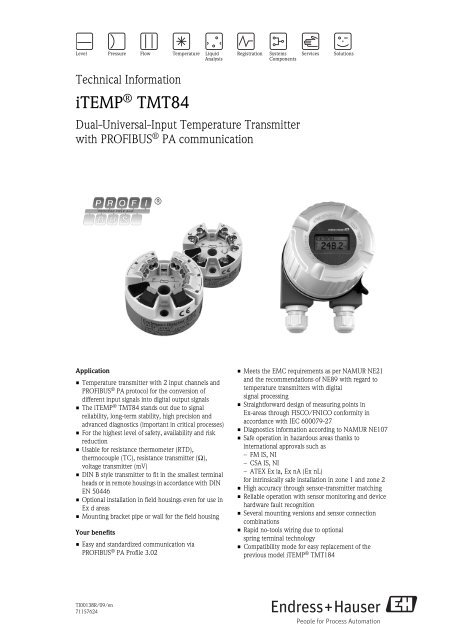
Technical Information<br />
<strong>iTEMP</strong> ® <strong>TMT84</strong><br />
Dual-Universal-Input Temperature Transmitter<br />
with PROFIBUS ® PA communication<br />
Application<br />
• Temperature transmitter with 2 input channels and<br />
PROFIBUS ® PA protocol for the conversion of<br />
different input signals into digital output signals<br />
• The <strong>iTEMP</strong> ® <strong>TMT84</strong> stands out due to signal<br />
reliability, long-term stability, high precision and<br />
advanced diagnostics (important in critical processes)<br />
• For the highest level of safety, availability and risk<br />
reduction<br />
• Usable for resistance thermometer (RTD),<br />
thermocouple (TC), resistance transmitter (Ω),<br />
voltage transmitter (mV)<br />
• DIN B style transmitter to fit in the smallest terminal<br />
heads or in remote housings in accordance with DIN<br />
EN 50446<br />
• Optional installation in field housings even for use in<br />
Ex d areas<br />
• Mounting bracket pipe or wall for the field housing<br />
Your benefits<br />
• Easy and standardized communication via<br />
PROFIBUS ® PA Profile 3.02<br />
TI00138R/09/en<br />
71157624<br />
• Meets the EMC requirements as per NAMUR NE21<br />
and the recommendations of NE89 with regard to<br />
temperature transmitters with digital<br />
signal processing<br />
• Straightforward design of measuring points in<br />
Ex-areas through FISCO/FNICO conformity in<br />
accordance with IEC 600079-27<br />
• Diagnostics information according to NAMUR NE107<br />
• Safe operation in hazardous areas thanks to<br />
international approvals such as<br />
–FM IS, NI<br />
– CSA IS, NI<br />
– ATEX Ex ia, Ex nA (Ex nL)<br />
for intrinsically safe installation in zone 1 and zone 2<br />
• High accuracy through sensor-transmitter matching<br />
• Reliable operation with sensor monitoring and device<br />
hardware fault recognition<br />
• Several mounting versions and sensor connection<br />
combinations<br />
• Rapid no-tools wiring due to optional<br />
spring terminal technology<br />
• Compatibility mode for easy replacement of the<br />
previous model <strong>iTEMP</strong> ® TMT184
Function and system design<br />
Measuring principle Electronic recording and conversion of various input signals in industrial temperature measurement.<br />
Measuring system<br />
Application examples<br />
m Two sensors with measuring input (RTD or TC) in remote installation with the following advantages: drift warning,<br />
sensor backup function and temperature-dependent switching<br />
n Built-in head transmitter - 1 x RTD/TC or 2 x RTD/TC as redundancy<br />
<strong>TMT84</strong><br />
Endress+Hauser is a producer of a wide range of resistance thermometers, thermocouples and matching<br />
thermowells.<br />
In conjunction with these components, the temperature transmitter forms a complete measuring point for<br />
various applications in the industrial sector.<br />
Device architecture<br />
System integration via PROFIBUS ® PA<br />
2 Endress+Hauser<br />
A0007667<br />
A0009166-EN
<strong>TMT84</strong><br />
The temperature transmitter is a two-wire device with two measuring inputs. Using PROFIBUS ® PA, the<br />
device transfers converted signals from resistance thermometers and thermocouples in addition to other<br />
resistance and millivolt signals. The device is powered via the PROFIBUS ® PA bus and can be installed as an<br />
intrinsically safe apparatus in zone 1 hazardous areas. The device is used for instrumentation purposes in the<br />
terminal head form B as per DIN EN 50446. Data transfer takes place via 4 analog input (AI) function blocks:<br />
Sensor diagnosis functions<br />
Sensor diagnoses such as cable open circuit, short-circuit, cable corrosion, wiring error and device hardware<br />
error are supported. In addition, the work area of the sensor and the ambient temperature are monitored.<br />
2-channel functions<br />
These functions increase the reliability and availability of the process values:<br />
• Sensor backup switches to the second sensor if the primary sensor fails.<br />
• Drift warning or alarm if the deviation between sensor 1 and sensor 2 is less than or greater than a predefined<br />
limit value.<br />
• Temperature-dependent switching between sensors which have advantages in different ranges.<br />
Compatibility mode<br />
For a easy replacement of the previous model <strong>iTEMP</strong> ® TMT184 with the <strong>TMT84</strong> a compatibility mode is<br />
available. The switching between the standard mode and compatibility mode in the <strong>iTEMP</strong> ® <strong>TMT84</strong> is done<br />
automatically during the connection establishment of the cyclic communication.<br />
The Following points have to receive attention:<br />
• Only PROFIBUS ® PA-Profile 3.0 is supported.<br />
• Only 1-channel operation possible.<br />
• The diagnostics and status handling is equal to the previous model TMT184.<br />
• The previous model TMT184 software locking is not available.<br />
Endress+Hauser 3
Input<br />
Measured variable Temperature (temperature linear transmission behavior), resistance and voltage.<br />
<strong>TMT84</strong><br />
Measuring range The transmitter records different measuring ranges depending on the sensor connection and input signals (see<br />
"Type of input").<br />
Type of input It is possible to connect two sensors which are independent of each other. The measuring inputs are not<br />
galvanically isolated from each other.<br />
Type of input Designation Measuring range limits<br />
Resistance thermometer<br />
(RTD)<br />
as per IEC 60751<br />
(α = 0.00385)<br />
as per JIS C1604-81<br />
(α = 0.003916)<br />
as per DIN 43760<br />
(α = 0.006180)<br />
as per Edison Copper Winding<br />
No.15 (α = 0.004274)<br />
as per Edison Curve<br />
(α = 0.006720)<br />
as per GOST<br />
(α = 0.003911)<br />
as per GOST<br />
(α = 0.004278)<br />
Pt100<br />
Pt200<br />
Pt500<br />
Pt1000<br />
4 Endress+Hauser<br />
Pt100<br />
Ni100<br />
Ni1000<br />
Cu10<br />
Ni120<br />
Pt50<br />
Pt100<br />
Cu50, Cu100<br />
Pt100 (Callendar-Van Dusen)<br />
Polynomial nickel<br />
Polynomial copper<br />
-200 to 850 °C (-328 to 1562 °F)<br />
-200 to 850 °C (-328 to 1562 °F)<br />
-200 to 250 °C (-328 to 482 °F)<br />
-200 to 250 °C (-238 to 482 °F)<br />
-200 to 649 °C (-328 to 1200 °F)<br />
-60 to 250 °C (-76 to 482 °F)<br />
-60 to 150 °C (-76 to 302 °F)<br />
-100 to 260 °C (-148 to 500 °F)<br />
-70 to 270 °C (-94 to 518 °F)<br />
-200 to 1100 °C (-328 to 2012 °F)<br />
-200 to 850 °C (-328 to 1562 °F)<br />
-200 to 200 °C (-328 to 392 °F)<br />
10 to 400 Ω<br />
10 to 2000 Ω<br />
10 to 400 Ω<br />
10 to 2000 Ω<br />
10 to 400 Ω<br />
10 to 2000 Ω<br />
• Connection type: 2-wire, 3-wire or 4-wire connection, sensor current: ≤ 0.3 mA<br />
• For 2-wire circuit, compensation for wire resistance possible (0 to 30 Ω)<br />
• For 3-wire and 4-wire connection, sensor wire resistance up to max. 50 Ω per<br />
wire<br />
Resistance transmitter Resistance Ω 10 to 400 Ω<br />
10 to 2000 Ω<br />
Thermocouples (TC)<br />
as per IEC 584, Part 1<br />
as per ASTM E988<br />
as per DIN 43710<br />
Type B (PtRh30-PtRh6)<br />
Type E (NiCr-CuNi)<br />
Type J (Fe-CuNi)<br />
Type K (NiCr-Ni)<br />
Type N (NiCrSi-NiSi)<br />
Type R (PtRh13-Pt)<br />
Type S (PtRh10-Pt)<br />
Type T (Cu-CuNi)<br />
Type C (W5Re-W26Re)<br />
Type D (W3Re-W25Re)<br />
Type L (Fe-CuNi)<br />
Type U (Cu-CuNi)<br />
0 to +1820 °C (32 to 3308 °F)<br />
-270 to +1000 °C (-454 to 1832 °F)<br />
-210 to +1200 °C (-346 to 2192 °F)<br />
-270 to +1372 °C (-454 to 2501 °F)<br />
-270 to +1300 °C (-454 to 2372 °F)<br />
-50 to +1768 °C (-58 to 3214 °F)<br />
-50 to +1768 °C (-58 to 3214 °F)<br />
-270 to +400 °C (-454 to 752 °F)<br />
0 to +2315 °C (32 to 4199 °F)<br />
0 to +2315 °C (32 to 4199 °F)<br />
-200 to +900 °C (-328 to 1652 °F)<br />
-200 to +600 °C (-328 to 1112 °F)<br />
• 2-wire connection<br />
• Internal cold junction (Pt100, Class B)<br />
• External cold junction: value adjustable from -40 to +85 °C (-40 to +185 °F)<br />
• Maximum sensor resistance 10 kΩ (if the sensor resistance is greater than 10 kΩ,<br />
an error message is output in accordance with NAMUR NE89)
<strong>TMT84</strong><br />
When assigning both sensor inputs, the following connection combinations are possible:<br />
Input signal Input data: The transmitter is able to receive a cyclic value and its status sent by a master via PROFIBUS ® PA.<br />
That value and status is represented and can be read acyclically.<br />
Output<br />
Output signal • PROFIBUS ® PA in accordance with EN 50170 Volume 2, IEC 61158-2 (MBP), galvanically isolated;<br />
• FDE (Fault Disconnection Electronic) = 0 mA<br />
• Data transmission rate: supported baud rate = 31.25 kBit/s<br />
• Signal coding = Manchester II<br />
• Output data:<br />
Available values via AI blocks: temperature (PV), temp sensor 1 + 2, terminal temperature<br />
• In a control system the transmitter always operates as a slave and, dependent on the application, can<br />
exchange data with one or more masters.<br />
• In accordance with IEC 60079-27, FISCO/FNICO<br />
Breakdown information Status message in accordance with PROFIBUS ® PA Profile 3.01/3.02 specification.<br />
Linearization/transmission<br />
behavior<br />
Mains voltage filter 50/60 Hz<br />
Temperature linear, resistance linear, voltage linear<br />
Galvanic isolation U = 2 kV AC (sensor input to the output)<br />
Current consumption ≤ 11 mA<br />
Switch-on delay 8 s<br />
Type of input Designation Measuring range limits<br />
Voltage transmitter (mV) Millivolt transmitter (mV) -20 to 100 mV<br />
-5 to 30 mV<br />
Sensor<br />
input 2<br />
RTD or resistance<br />
transmitter, 2-wire<br />
RTD or resistance<br />
transmitter, 3-wire<br />
RTD or resistance<br />
transmitter, 4-wire<br />
Thermocouple (TC),<br />
voltage transmitter<br />
RTD or<br />
resistance<br />
transmitter, 2wire<br />
RTD or<br />
resistance<br />
transmitter, 3wire<br />
Sensor input 1<br />
RTD or<br />
resistance<br />
transmitter, 4wire<br />
Thermocouple<br />
(TC), voltage<br />
transmitter<br />
  - Â<br />
  - Â<br />
- - - -<br />
   Â<br />
Endress+Hauser 5
PROFIBUS ® PA basic data<br />
<strong>TMT84</strong><br />
Brief description of the blocks Physical Block<br />
The Physical Block contains all the data that clearly identify and characterize the device. It is like an<br />
electronicdevice nameplate. In addition to parameters that are needed to operate the device on the fieldbus,<br />
the Physical Block makes other information available such as the order code, device ID, hardware revision,<br />
software revision, device release, etc. Furthermore the display settings can be configured via the Physical Block.<br />
Electrical connection<br />
Manufacturer spec. ID-no.: Profile 3.0 ID-no.: Manufacturer specific GSD<br />
1551 (Hex) 9700 (Hex)<br />
9701 (Hex)<br />
9702 (Hex)<br />
9703 (Hex)<br />
Profile 3.0 GSD Device address or bus address Bitmaps<br />
Pa139700.gsd<br />
Pa139701.gsd<br />
Pa139702.gsd<br />
Pa139703.gsd<br />
Transducer Block "Sensor 1" and "Sensor 2"<br />
The Transducer Blocks of the transmitter contain all the measurement-related and device-specific parameters<br />
that are relevant for measuring the input variables.<br />
Analog Input (AI)<br />
In the AI function block, the process variables from the Transducer Blocks are prepared for subsequent<br />
automation functions in the control system (e.g. scaling, limit value processing).<br />
Power supply<br />
Terminal assignment of transmitter.<br />
Supply voltage U = 9 to 32 V DC, polarity independent (max. voltage U b = 35 V)<br />
EH021551.gsd<br />
(Profile 3.01 EH3x1551.gsd)<br />
126 (default) EH_1551_d.bmp<br />
EH_1551_n.bmp<br />
EH_1551_s.bmp<br />
If the <strong>TMT84</strong> operates in the compatibily mode, the device is identifying with the manufacturer<br />
specific ID-no.: 1523 (Hex) - TMT184 in the cyclic data exchange.<br />
6 Endress+Hauser<br />
A0007285-EN
<strong>TMT84</strong><br />
Response time 1 s per channel<br />
Reference operating<br />
conditions<br />
Performance characteristics<br />
• Calibration temperature: + 25 °C ± 5 K (77 °F ± 9 °F)<br />
• Supply voltage: 24 V DC<br />
• 4-wire circuit for resistance adjustment<br />
Resolution Resolution A/D converter = 18 bit<br />
Maximum measured error<br />
The accuracy data are typical values and correspond to a standard deviation of ± 3σ (normal<br />
distribution), i.e. 99.8% of all the measured values achieve the given values or better values.<br />
Resistance thermometers (RTD)<br />
Thermocouples (TC)<br />
Sensor transmitter matching<br />
RTD sensors are one of the most linear temperature measuring elements. Nevertheless, the output must be<br />
linearized. To improve temperature measurement accuracy significantly, the device enables the use of two<br />
methods:<br />
• Callendar-Van Dusen coefficients (Pt100 resistance thermometer)<br />
The Callendar-Van Dusen equation is described as:<br />
The coefficients A, B and C are used to match the sensor (platinum) and transmitter in order to improve the<br />
accuracy of the measuring system. The coefficients for a standard sensor are specified in IEC 751. If no<br />
standard sensor is available or if greater accuracy is required, the coefficients for each sensor can be<br />
determined specifically by means of sensor calibration.<br />
• Linearization for copper/nickel resistance thermometers (RTD)<br />
The polynomial equations for nickel are described as:<br />
The equations for copper, subject to temperature, are described as:<br />
T = -50 °C to 200 °C (-58 °F to 392 °F)<br />
T = -180 °C to -50 °C (-292 °F to -58 °F)<br />
Designation Performance characteristics<br />
Cu100, Pt100, Ni100, Ni120<br />
Pt500<br />
Cu50, Pt50, Pt1000, Ni1000<br />
Cu10, Pt200<br />
Type: K, J, T, E, L, U<br />
Type: N, C, D<br />
Type: S, B, R<br />
Resistance transmitters (Ω) 10 to 400 Ω<br />
10 to 2000 Ω<br />
0.1 °C (0.18 °F)<br />
0.3 °C (0.54 °F)<br />
0.2 °C (0.36 °F)<br />
1 °C (1.8 °F)<br />
0.25 °C (0.45 °F)<br />
0.5 °C (0.9 °F)<br />
1.0 °C (1.8 °F)<br />
Measuring range Performance characteristics<br />
± 0.04 Ω<br />
± 0.8 Ω<br />
Voltage transmitters (mV) -20 to 100 mV ± 10 μV<br />
These coefficients A, B and C are used for the linearization of nickel or copper resistance thermometers<br />
(RTD). The exact values of the coefficients derive from the calibration data and are specific to each sensor.<br />
Endress+Hauser 7<br />
-100<br />
-100<br />
3<br />
3
Non-repeatability As per EN 61298-2<br />
<strong>TMT84</strong><br />
Sensor transmitter matching using one of the above-named methods significantly improves the temperature<br />
measurement accuracy of the entire system. This is due to the fact that to calculate the temperature measured,<br />
the transmitter uses the specific data pertaining to the connected sensor instead of using the standardized<br />
sensor curve data.<br />
Long-term stability ≤ 0.1 °C/year (≤ 0.18 °F/year) in reference operating conditions<br />
Influence of ambient temperature<br />
(temperature drift)<br />
Influence of reference point<br />
(cold junction)<br />
Physical input measuring range of sensors Non-repeatability<br />
10 to 400 Ω Cu10, Cu50, Cu100, Pt50, Pt100, Ni100, Ni120 15 mΩ<br />
10 to 2000 Ω Pt200, Pt500, Pt1000, Ni1000 100 ppm x measured value<br />
-20 to 100 mV Thermocouples type: C, D, E, J, K, L, N, U 4 μV<br />
-5 to 30 mV Thermocouples type: B, R, S, T 3 μV<br />
Impact on accuracy when ambient temperature changes by 1 K (1.8 °F):<br />
Input 10 to 400 Ω 0.001% of the measured value, min. 1 mΩ<br />
Input 10 to 2000 Ω 0.001% of the measured value, min. 10 mΩ<br />
Input -20 to 100 mV 0.001% of the measured value, min. 0.2 μV<br />
Input -5 to 30 mV 0.001% of the measured value, min. 0.2 μV<br />
Typical sensitivity of resistance thermometers<br />
Pt: 0.00385 * R nom /K Cu: 0.0043 * R nom /K Ni: 0.00617 * R nom /K<br />
Example Pt100: 0.00385 x 100 Ω/K = 0.385 Ω/K<br />
Typical sensitivity of thermocouples<br />
B: 9 μV/K at<br />
1000 °C (1832 °F)<br />
L: 60 μV/K at<br />
500 °C (932 °F)<br />
C: 18 μV/K at<br />
1000 °C (1832 °F)<br />
N: 38 μV/K at<br />
500 °C (932 °F)<br />
D: 20 μV/K at<br />
1000 °C (1832 °F)<br />
R: 13 μV/K at<br />
1000 °C (1832 °F)<br />
E: 81 μV/K at<br />
500 °C (932 °F)<br />
S: 11 μV/K at<br />
1000 °C (1832 °F)<br />
Example of calculating the measured error with ambient temperature drift:<br />
• Input temperature drift ϑ = 10 K (18 °F), Pt100, measuring range 0 to 100 °C (32 to 212 °F)<br />
• Maximum process temperature: 100 °C (212 °F)<br />
• Measured resistance value: 138.5 Ω (DIN EN 60751) at maximum process temperature<br />
Typical temperature drift in Ω: (0.001% of 138.5 Ω) * 10 = 0.01385 Ω<br />
Conversion to Kelvin: 0.01385 Ω / 0.385 Ω/K = 0.04 K (0.054 °F)<br />
J: 56 μV/K at<br />
500 °C (932 °F)<br />
T: 46μV/K at<br />
100 °C (212 °F)<br />
K: 43 μV/K at<br />
500 °C (932 °F)<br />
U: 70 μV/K at<br />
500 °C (932 °F)<br />
Pt100 DIN EN 60751 Cl. B, accuracy ± 1 K (± 1.8 °F), internal reference point for thermocouples TC<br />
8 Endress+Hauser
<strong>TMT84</strong><br />
Installation conditions<br />
Installation instructions • Mounting location:<br />
A: Terminal head as per DIN EN 50446 form B, direct installation onto insert with cable entry (middle hole 7 mm (0.28 in))<br />
B: Separated from process in field housing, wall or pipe mounting<br />
C: With DIN rail clip on top-hat rail as per IEC 60715 (TH35)<br />
•Orientation:<br />
No restrictions<br />
Environment conditions<br />
Ambient temperature range -40 to +85 °C (-40 to +185 °F), for hazardous areas see Ex documentation (XA, CD) and "Approvals" section.<br />
Storage temperature -40 to +100 °C (-40 to +212 °F)<br />
Altitude up to 4000 m (4374.5 yd) above mean sea level in accordance with IEC 61010-1, CSA 1010.1-92<br />
Climate class as per IEC 60654-1, Class C<br />
A B<br />
Humidity • Condensation as per IEC 60068-2-33 permitted<br />
• Max. rel. humidity: 95% as per IEC 60068-2-30<br />
Degree of protection • IP00 with screw terminals. In the installed state, it depends on the terminal head or field housing used.<br />
• IP30 with spring terminals<br />
• IP66/67 when installed in field housing TA30A, TA30D or TA30H<br />
Shock and vibration resistance 10 to 2000 Hz for 5g as per IEC 60068-2-6<br />
C<br />
Endress+Hauser 9<br />
120 mm<br />
(4.72 in)<br />
120 mm<br />
(4.72 in)<br />
A0016762
Electromagnetic compatibility<br />
(EMC)<br />
CE EMC compliance<br />
The device meets all of the requirements mentioned in IEC 61326-1, 2007 and NAMUR NE21:2006.<br />
<strong>TMT84</strong><br />
This recommendation is a consistent determination whether the devices used in laboratories and in process<br />
control systems are immune to interference, thus increasing their functional safety.<br />
Measuring category Measuring category II as per IEC 61010-1. The measuring category is provided for measuring on power circuits<br />
that are directly connected electrically with the low-voltage network.<br />
Degree of contamination Pollution degree 2 as per IEC 61010-1.<br />
Mechanical construction<br />
Design, dimensions Specifications in mm (in)<br />
Head transmitter<br />
ESD (electrostatic discharge) IEC 61000-4-2 6 kV cont., 8 kV air<br />
Electromagnetic fields IEC 61000-4-3 0.08 to 4 GHz 10 V/m<br />
Burst (fast transients) IEC 61000-4-4 1 kV<br />
Surge IEC 61000-4-5 1 kV asym.<br />
Conducted RF IEC 61000-4-6 0.01 to 80 MHz 10 V<br />
B<br />
Ø5 (0.2)<br />
Model with screw terminals<br />
Pos. A: Spring range L ≥5 mm (not applicable to US - M4 mounting screws)<br />
Pos. B: Fixing elements for detachable measured value display<br />
Pos. C: Interface for contacting measured value display<br />
Model with spring terminals. The same dimensions except for height of housing.<br />
Field housings<br />
All terminal heads have an internal shape and size in accordance with DIN EN 50446, flat face and a<br />
thermometer connection of M24x1.5. Cable glands: M20x1.5<br />
10 Endress+Hauser<br />
Ø7 (0.28)<br />
C<br />
33 (1.3)<br />
Ø44 (1.73)<br />
A<br />
24.1 (0.95)<br />
A0007301<br />
A0007672
<strong>TMT84</strong><br />
TA30A Specification<br />
68.5 (2.7)<br />
Endress+Hauser 11<br />
A0009820<br />
TA30A with display window in cover Specification<br />
A0009821<br />
TA30H Specification<br />
89.5 (3.52)<br />
15.5 (0.6)<br />
20.5 (0.8)<br />
28<br />
(1.1)<br />
78 (3.1)<br />
107.5 (4.23)<br />
125 (4.92)<br />
28<br />
(1.1) 78 (3.01)<br />
A0009832<br />
•Two cable entries<br />
• Temperature: -50 °C to +150 °C (-58 °F to +302 °F) without<br />
cable gland<br />
• Material: aluminum, polyester powder coated<br />
Seals: silicone<br />
• Cable entry incl. glands: ½"NPT and M20x1.5<br />
• Head color: blue RAL 5012<br />
• Cap color: gray RAL 7035<br />
• Weight: 330 g (11.64 oz)<br />
•Two cable entries<br />
• Temperature: -50 °C to +150 °C (-58 °F to +302 °F) without<br />
cable gland<br />
• Material: aluminum, polyester powder coated<br />
Seals: silicone<br />
• Cable entry incl. glands: ½"NPT und M20x1.5<br />
• Head color: blue RAL 5012<br />
• Cap color: gray RAL 7035<br />
• Weight: 420 g (14.81 oz)<br />
• Flameproof (XP) version, explosion-protected, captive screw cap,<br />
with two cable entries<br />
• Temperature: -50 °C to +150 °C (-58 °F to +302 °F) for rubber<br />
seal without cable gland (observe max. permitted temperature of<br />
the cable gland!)<br />
• Material: aluminum; polyester powder coated<br />
• Cable entry glands: ½"NPT, M20x1.5<br />
• Head color: blue RAL 5012<br />
• Cap color: gray RAL 7035<br />
• Weight: 640 g (22.6 oz)
TA30H with display window in cover Specification<br />
Weight • Head transmitter: approx. 40 to 50 g (1.4 to 1.8 oz)<br />
• Field housing: see specifications<br />
<strong>TMT84</strong><br />
Material All materials used are RoHS-compliant.<br />
Head transmitter<br />
• Housing: Polycarbonate (PC), complies with UL94 HB flammability standard (HB: horizontal burning test)<br />
• Terminals<br />
Screw terminals: Nickel-plated brass and gold-plated contact<br />
Spring terminals: Tin-plated brass, contact spring V2A<br />
• Potting: WEVO PU 403 FP / FL, according to UL94 V0 flammability standard (V0: vertical burning test)<br />
12 Endress+Hauser<br />
A0009831<br />
TA30D Specification<br />
110 (4.3)<br />
15.5 (0.6)<br />
28<br />
(1.1) 78 (3.1)<br />
A0009822<br />
Maximum ambient temperature for cable glands and fieldbus connectors<br />
Type Temperature range<br />
Cable gland polyamide ½" NPT, M20x1.5<br />
(non-Ex)<br />
Cable gland polyamide M20x1.5<br />
(for dust ignition-proof area)<br />
107.5 (4.23)<br />
Cable gland brass ½" NPT, M20x1.5<br />
(for dust ignition-proof area)<br />
• Flameproof (XP) version, explosion-protected, captive screw cap,<br />
with two cable entries<br />
• Temperature: -50 °C to +150 °C (-58 °F to +302 °F) for rubber<br />
seal without cable gland (observe max. permitted temperature of<br />
the cable gland!)<br />
• Material: aluminum; polyester powder coated<br />
• Cable entry glands: ½"NPT, M20x1.5<br />
• Head color: blue RAL 5012<br />
• Cap color: gray RAL 7035<br />
• Weight: 860 g (30.33 oz)<br />
• Two cable entries<br />
• Temperature: -50 °C to +150 °C (-58 °F to +302 °F) without<br />
cable gland<br />
• Material: aluminum, polyester powder coated<br />
Seals: silicone<br />
• Cable entry incl. glands: ½"NPT, M20x1.5<br />
• Two head transmitters can be mounted. In the standard version,<br />
one transmitter is mounted in the terminal head cover and an<br />
additional terminal block is installed directly on the insert.<br />
• Head color: blue RAL 5012<br />
• Cap color: gray RAL 7035<br />
• Weight: 390 g (13.75 oz)<br />
-40...+100 °C (-40...+212 °F)<br />
-20...+95 °C (-4...+203 °F)<br />
-20...+130 °C (-4...+266 °F)<br />
Fieldbus connector (M12x1 PA, 7/8" FF) -40...+105 °C (-40...+221 °F)
<strong>TMT84</strong><br />
Field housing: see specifications<br />
Terminals Choice of screw or spring terminals (see "Design, dimensions" diagram) for sensor and fieldbus wires:<br />
Display and operating<br />
elements<br />
Terminals version Wire version Conductor cross-section<br />
Screw terminals (with latches at the<br />
fieldbus terminals for easy connection of a<br />
handheld terminal, e.g. DXR375)<br />
Spring terminals<br />
Stripped length = min. 10 mm (0.39 in)<br />
Human interface<br />
There are no display or operating elements present at the transmitter.<br />
Optional the plug-on display TID10 can be used in connection with the transmitter. It will display information<br />
regarding the actual measured value and the measurement point identification. In the event of a fault in the<br />
measurement chain this will be displayed in inverse color showing the channel ident and diagnostics code.<br />
DIP-switches can be found on the rear of the display. This enables the hardware set-up such as the PROFIBUS ®<br />
device address.<br />
Pluggable display TID10<br />
Rigid or flexible ≤ 2.5 mm 2 (14 AWG)<br />
If the transmitter is installed in a field housing and used with a display, a housing with glas window needs to<br />
be used.<br />
Remote operation The configuration of PROFIBUS ® PA functions and of device-specific parameters is performed via fieldbus<br />
communication. Special configuration systems provided by various manufacturers are available for this<br />
purpose.<br />
Sources of supply of the device data files (GSD) and device drivers:<br />
• GSD-file: www.endress.com (→ Download → Software)<br />
Rigid or flexible 0.2...1.5 mm 2 (24...16 AWG)<br />
Flexible with wire-end ferrules<br />
without plastic ferrule<br />
Flexible with wire-end ferrules<br />
with plastic ferrule<br />
0.25...1.5 mm 2 (24...16 AWG)<br />
0.25...0.75 mm 2 (24...18 AWG)<br />
No ferrules have to be used when connecting flexible wires to spring terminals.<br />
Configuration software<br />
Endress+Hauser FieldCare (DTM)<br />
SIMATIC PDM (EDD)<br />
Endress+Hauser 13<br />
a0009818
• Profile GSD-file: www.profibus.com<br />
• FieldCare/DTM: www.endress.com (→ <strong>Automation</strong> → Fieldbus → Fieldbus device integration)<br />
• SIMATIC PDM: www.endress.com (→ <strong>Automation</strong> → Fieldbus → Fieldbus device integration) or<br />
www.fielddevices.com<br />
<strong>TMT84</strong><br />
Bus address The device address or bus address is set up either with the configuration software or via DIP switches on the<br />
optional display.<br />
Certificates and approvals<br />
CE-Mark The device meets the legal requirements of the EC directives. Endress+Hauser confirms that the device has<br />
been successfully tested by applying the CE mark.<br />
Hazardous area approvals ATEX approval<br />
<strong>TMT84</strong> ATEX II 1G Ex ia IIC T6/T5/T4<br />
Power supply (Terminals + and -) U i ≤ 17.5 V DC<br />
I i ≤ 500 mA<br />
C i ≤ 5 nF<br />
L i = negligibly small<br />
Suitable for connecting to a fieldbus system as per the FISCO/FNICO model<br />
Sensor circuit (Terminals 3 to 7) U 0 ≤ 7.2 V DC<br />
I 0 ≤ 25.9 mA<br />
P 0 ≤ 46.7 mW<br />
C i = negligibly small<br />
L i = negligibly small<br />
Max. connection data Ex ia IIC<br />
Ex ia IIB<br />
Ex ia IIA<br />
Temperature range<br />
T6<br />
T5<br />
T4<br />
L 0 = 20 mH<br />
L 0 = 50 mH<br />
L 0 = 100 mH<br />
Zone 1, 2:<br />
Ta = -40 °C to +55 °C (-40 °F to 130 °F)<br />
Ta = -40 °C to +70 °C (-40 °F to 158 °F)<br />
Ta = -40 °C to +85 °C (-40 °F to 185 °F)<br />
Application:<br />
• Equipment category: potentially explosive gas and air mixtures (G)<br />
• Category 1 zone 0, 1 or 2<br />
or U i ≤ 24 V DC<br />
I i ≤ 250 mA<br />
C 0 = 0.7 μF<br />
C 0 = 4.6 μF<br />
C 0 = 6.0 μF<br />
Zone 0:<br />
Ta = -20 °C to +40 °C (-4 °F to 104 °F)<br />
Ta = -20 °C to +50 °C (-4 °F to 122 °F)<br />
Ta = -20 °C to +60 °C (-4 °F to 140 °F)<br />
For zone 0: potentially explosive steam and air mixtures may only occur under following<br />
atmospheric conditions:<br />
•- 20 °C ≤ Ta ≤ +60 °C (- 4 °F ≤ Ta ≤ +140 °F)<br />
•0.8 bar ≤ p ≤ 1.1 bar (11.6 psi ≤ p ≤ 16 psi)<br />
<strong>TMT84</strong> ATEX<br />
• II 2G Ex d IIC T6…T4 Gb<br />
• II 2D Ex tb IIIC T85 °C…T105 °C Db<br />
IEC<br />
• Ex d IIC T6…T4 Gb<br />
• Ex tb IIIC T85 °C…T105 °C Db<br />
Power supply (terminals + and -) U ≤ 35 V DC<br />
Output PROFIBUS ® PA<br />
Current consumption ≤ 11 mA<br />
Temperature range T6<br />
T5<br />
T4<br />
-40 °C ≤ Ta ≤ +65 °C<br />
-40 °C ≤ Ta ≤ +80 °C<br />
-40 °C ≤ Ta ≤ +85 °C<br />
14 Endress+Hauser
<strong>TMT84</strong><br />
<strong>TMT84</strong> ATEX<br />
• II 2G Ex d IIC T6…T4 Gb<br />
• II 2D Ex tb IIIC T85 °C…T105 °C Db<br />
IEC<br />
• Ex d IIC T6…T4 Gb<br />
• Ex tb IIIC T85 °C…T105 °C Db<br />
Maximum suface temperature housing T85°C<br />
T100°C<br />
T105°C<br />
Application (ATEX II 3G Ex nA II T6/T5/T4):<br />
• Equipment category: potentially explosive gas and air mixtures (G)<br />
• Category zone 2<br />
Application (ATEX II 3D):<br />
• Equipment category: potentially explosive dust and air mixtures (D)<br />
• Category zone 22<br />
FM approval<br />
Labeling: IS / I / 1 / ABCD / T4, Entity* or FISCO*;<br />
I / 0 / AEx ia IIC / T4 Ta, Entity* or FISCO*<br />
NI / I / 2 / ABCD / T4, NIFW* or FNICO*;<br />
FM XP, NI, DIP I, II, III / 1+2 / A-G<br />
*= Entity, FISCO, NIFW and FNICO parameters in accordance with control drawings (CD)<br />
Application:<br />
• Intrinsic safety<br />
• Non-incendive<br />
For connection data see table on ATEX approval ATEX II 1G<br />
CSA approval (Canadian Standard Association)<br />
Labeling:<br />
Class I, Div. 1, Groups A, B, C, D, Entity* or FISCO*;<br />
-40 °C ≤ Ta ≤ +65 °C<br />
-40 °C ≤ Ta ≤ +80 °C<br />
-40 °C ≤ Ta ≤ +85 °C<br />
<strong>TMT84</strong> ATEX II 3G Ex nA II T6/T5/T4<br />
ATEX II 3D<br />
Power supply (terminals + and -) U ≤ 35 V DC<br />
Output PROFIBUS ® PA<br />
Current consumption ≤ 11 mA<br />
Temperature range T6<br />
T5<br />
T4<br />
Ta = -40 °C to + 55 °C (-40 °F to 130 °F)<br />
Ta = -40 °C to + 70 °C (-40 °F to 158 °F)<br />
Ta = -40 °C to + 85 °C (-40 °F to 185 °F)<br />
<strong>TMT84</strong> II 3G Ex nL IIC T6/T5/T4<br />
Power supply<br />
(terminals + and -)<br />
Ui ≤ 32 V DC<br />
Ci ≤ 5 nF<br />
Li ≤ 10 μH<br />
Applicable for connection to a Fieldbus system according to FNICO-model<br />
Sensor circuit (terminals 3 to 7) Uo ≤ 7.2 VDC<br />
Io ≤ 25.9 mA<br />
Po ≤ 46.7 mW<br />
Max. connection values Ex nL IIC<br />
Ex nL IIB<br />
Ex nL IIA<br />
Temperature range T6<br />
T5<br />
T4<br />
Lo = 20 mH<br />
Lo = 50 mH<br />
Lo = 100 mH<br />
Ta = -40 °C to + 55 °C<br />
Ta = -40 °C to + 70 °C<br />
Ta = -40 °C to + 85 °C<br />
Co = 0.97 μF<br />
Co = 4.6 μF<br />
Co = 6 μF<br />
Endress+Hauser 15
Ex ia IIC<br />
Class I, Div.2, Groups A, B, C, D, NIFW* or FNICO*;<br />
Ex nA IIC<br />
CSA XP, NI, DIP I, II, III / 1+2 / A-G<br />
*= Entity, FISCO, NIFW and FNICO parameters in accordance with control drawings (CD)<br />
Application:<br />
• Intrinsic safety<br />
• Non-incendive<br />
For connection data see table on ATEX approval ATEX II 1G<br />
For further details on the available Ex versions (ATEX, CSA, FM, etc.), please contact your nearest<br />
Endress+Hauser sales organisation. All relevant data for hazardous areas can be found in separate Ex<br />
documentation. If required, please request copies from us or your Endress+Hauser sales organisation.<br />
UL Recognized component to UL61010-1<br />
Other standards and<br />
guidelines<br />
CSA GP CSA General Purpose<br />
• IEC 60529:<br />
Degrees of protection through housing (IP code)<br />
• IEC 61158-2:<br />
Fieldbus standard<br />
• IEC 61326-1:2007:<br />
Electromagnetic compatibility (EMC requirements)<br />
• IEC 60068-2-27 and IEC 60068-2-6:<br />
Shock and vibration resistance<br />
•NAMUR<br />
International user association of automation technology in process industries<br />
<strong>TMT84</strong><br />
Certification PROFIBUS ® PA The temperature transmitter is certified and registered by the PNO (PROFIBUS ® user organization e.V.). The<br />
device thus meets all the requirements of the specifications following:<br />
• Certified according to PROFIBUS ® PA Profile 3.02<br />
• The device can also be operated with certified devices of other manufacturers (interoperability)<br />
Ordering information<br />
Detailed ordering information is available from the following sources:<br />
•In the Product Configurator on the Endress+Hauser website:<br />
www.endress.com → Select country→ Instruments → Select device→ Product page function: Configure<br />
this product<br />
• From your Endress+Hauser Sales Center:<br />
www.endress.com/worldwide<br />
Product Configurator - the tool for individual product configuration:<br />
• Up-to-the-minute configuration data<br />
• Depending on the device: Direct input of measuring point-specific information such as measuring range or<br />
operating language<br />
• Automatic verification of exclusion criteria<br />
• Automatic creation of the order code and its breakdown in PDF or Excel output format<br />
• Ability to order directly in the Endress+Hauser Online Shop<br />
16 Endress+Hauser
<strong>TMT84</strong><br />
Accessories<br />
Type Order code<br />
Display TID10 for Endress+Hauser transmitters <strong>iTEMP</strong> ® TMT8x, pluggable TID10-xx<br />
Field housing TA30x for Endress+Hauser head transmitter TA30x-xx<br />
DIN rail clip according to IEC 60715 (TH35) for head transmitter mounting 51000856<br />
Standard - DIN mounting set (2 screws + springs, 4 securing disks and 1<br />
display connector cover)<br />
The following accessories are contained in the scope of delivery:<br />
• Multi-language Brief Operating Instructions as hard copy<br />
• Supplementary documentation ATEX:<br />
ATEX Safety instructions (XA), Control Drawings (CD)<br />
• Operating Instructions on CD-ROM<br />
• Mounting material for head transmitter<br />
• Mounting material for field housings (pipe or wall mounting)<br />
Documentation<br />
71044061<br />
US - M4 mounting screws (2 screws M4 and 1 display connector cover) 71044062<br />
Fieldbus connector<br />
(PROFIBUS ® PA):<br />
Threaded connection<br />
• M20x1.5<br />
•NPT ½"<br />
• M20x1.5<br />
Stainless steel wall mounting bracket<br />
Stainless steel pipe mounting bracket<br />
Cable connecting thread<br />
•M12<br />
•M12<br />
•7/8"<br />
71090687<br />
71005802<br />
71089147<br />
71123339<br />
71123342<br />
• Operating instructions "<strong>iTEMP</strong> ® <strong>TMT84</strong>" (BA00257R/09/en) on CD-ROM and associated Brief Operating<br />
Instructions "<strong>iTEMP</strong> ® <strong>TMT84</strong>" (KA00258R/09/a2)<br />
• Ex supplementary documentation:<br />
ATEX II 1G Ex ia IIC: XA069R/09/a3<br />
ATEX II 3G Ex nA II: XA073R/09/a3<br />
ATEX II 3D Ex tD (iaD) A22: XA074R/09/a3<br />
ATEX II 2(1)G Ex ia IIC: XA01012T/09/a3<br />
ATEX II 2G Ex d IIC and ATEX II 2D Ex tb IIIC: XA01007T/09/a3<br />
• Operating instructions "Display TID10" (BA262R/09/c4)<br />
• Guidelines for planning and commissioning "PROFIBUS ® DP/PA" (BA034S/04/en)<br />
Endress+Hauser 17
Instruments International<br />
Endress+Hauser<br />
Instruments International AG<br />
Kaegenstrasse 2<br />
4153 Reinach<br />
Switzerland<br />
Tel.+41 61 715 81 00<br />
Fax+41 61 715 25 00<br />
www.endress.com<br />
info@ii.endress.com<br />
TI00138R/09/en/02.11<br />
71157624<br />
FM9.0<br />
<strong>TMT84</strong>