Modeling Frame and Edge Heat Transfer with THERM
Modeling Frame and Edge Heat Transfer with THERM
Modeling Frame and Edge Heat Transfer with THERM

You also want an ePaper? Increase the reach of your titles
YUMPU automatically turns print PDFs into web optimized ePapers that Google loves.
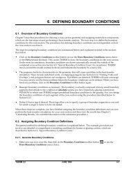
6. MODELING FRAME AND EDGE HEAT TRANSFERWITH <strong>THERM</strong>6.1. OverviewIn order to calculate the total product U-factor, the U-factor must be determined for the followingcomponents, <strong>and</strong> then these values must be area-weighted for the whole product:• Center-of-glazing values from WINDOW• <strong>Frame</strong> <strong>and</strong> edge-of-glazing values from <strong>THERM</strong>The NFRC 100: Procedures for Determining Fenestration Product U-factors is the definitive source for themethodology for calculating U-factors, <strong>and</strong> should be used for situations not covered in this manual. Inaddition, NFRC Technical Interpretations supplement the NFRC 100 document, <strong>and</strong> these should also beconsulted when questions arise.6.2 Cross-Sections to be ModeledThe fenestration product b eing modeled must be divided into the cross-sections which completely define theheat transfer through the product. <strong>THERM</strong> is used to calculate the U-factor values for the edge-of-glazing aswell as the frame components (sill, head, jamb, meeting rail, <strong>and</strong> divider).The operator type of the fenestration product, as well as the configuration of each component of the frame,will determine the number of cross sections that must be modeled. Table 6-1 lists the minimum <strong>and</strong>maximum cross sections that must be modeled for each operator type, <strong>and</strong> Figure 6-1 illustrates where thecross sections must be taken. The maximum assumes that each frame cross section is unique <strong>and</strong> thereforemust be modeled. If there are some cross sections of the frame which are identical, such as a fixed window<strong>with</strong> the same cross section for the jambs, then only one cross section needs to be modeled for the jamb.However, the new modeling assumptions for cavities when modeling Condensation Resistance, based on ISO15099, require that different cross sections be modeled for head, sill, <strong>and</strong> jambs if those cross sections containframe cavities. If only U-factor is being modeled, the head <strong>and</strong> the sill can be combined into one calculation ifthe geometries for each are the same.Although all the Product types listed in Table 1 of NFRC 100 are not listed here in Table 6-1 or Figure 6-1,these four basic categories cover all the geometries in NFRC 100.<strong>THERM</strong>5.2/WINDOW5.2 NFRC Simulation Manual July 2006 6-1
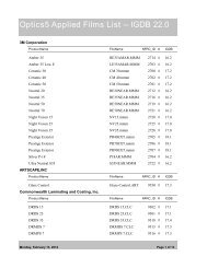
6.2 Cross-Sections to be Modeled 6. MODELING FRAME AND EDGE HEAT TRANSFER WITH <strong>THERM</strong>.(Fixed,Picture,Transom,Casement,Awning, etc)3If Jambs are the sameTable 6-1. Cross sections to be modeledOperator Number of Cross Sections to ModelType Minimum Maximum Cross SectionsSingle Lite CR & U CalcU only Calc4 • Head• Jamb (1 or 2)• SillTwo LiteVertical(VerticalSlider)Two LiteHorizontal(HorizontalSlider,Sliding PatioDoor)Two-litecasement,(WindowWall, CurtainWall)5If Left <strong>and</strong> RightUpper Jambs are thesame, <strong>and</strong> Left <strong>and</strong>Right Lower Jambsare the same2If Head <strong>and</strong> Sill are thesame4If Head <strong>and</strong> Sill are thesame7 5If Head <strong>and</strong> Sill are thesame4If Left <strong>and</strong> RightHead are the same,Left <strong>and</strong> Right Sillsare the same, <strong>and</strong>Left <strong>and</strong> Right Jambsare the same.7 • Head Fixed or Vent• Jamb Fixed & Vent• Sill Fixed & Vent• Meeting Rail7 • Head Fixed & Vent• Jamb Fixed & Vent• Sill Fixed & Vent• Meeting Rail4 7 • Head Fixed & Vent• Jamb Fixed & Vent• Sill Fixed & Vent• Meeting Rail6-2 July 2006 <strong>THERM</strong>5.2/WINDOW5.2 NFRC Simulation Manual
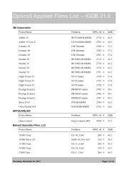
6. MODELING FRAME AND EDGE HEAT TRANSFER WITH <strong>THERM</strong> 6.2 Cross-Sections to be ModeledFixed(Max. 4, Min 3 cross sections)Projecting/Awning(Max. 4, Min 3 cross sections)Casement(Max. 4, Min 3 cross sections)Vertical Slider(Max. 7, Min 5 cross sections)Horizontal Slider(Max. 7, Min 4 cross sections)Figure 6-1. Minimum <strong>and</strong> maximum cross sections to be modeled based on operator type.<strong>THERM</strong>5.2/WINDOW5.2 NFRC Simulation Manual July 2006 6-3
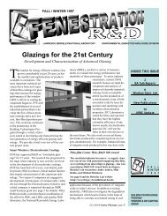
6.3 Draw the Cross Sections 6. MODELING FRAME AND EDGE HEAT TRANSFER WITH <strong>THERM</strong>6.3 Draw the Cross SectionsAfter the number of cross sections to be modeled has been determined, draw them in <strong>THERM</strong>. The Section 5,"Drawing Cross-Section Geometry" in the <strong>THERM</strong> User's Manual contains detailed instructions about how todraw cross sections. This section of the <strong>THERM</strong> NFRC Simulation Manual contains information pertainingspecifically to the NFRC procedures.6.3.1. Getting Started − Drawings <strong>and</strong> DXF FilesIn order to reproduce accurate cross sections in <strong>THERM</strong>, it is necessary to use dimensioned drawings <strong>and</strong>/orDXF files. Section 5.2, "Importing a DXF or Bitmap File as an Underlay" in the <strong>THERM</strong> User's Manual.If only dimensioned drawings are available (assembly drawings <strong>and</strong> die drawings), <strong>and</strong> there are no DXFfiles, it is still possible to create a cross-section in <strong>THERM</strong>. Section 5.5, "Drawing Using the Keyboard(Numeric Cursor Positioning)" of the <strong>THERM</strong> User's Manual.6.3.2. File Preferences -- Cross-Section TypeIt is extremely important to specify the Cross Section Type in the <strong>THERM</strong> File Properties dialog box(accessed from the File/Properties menu). The Cross Section Type, in combination <strong>with</strong> the glazing systemorientation, will determine how many of the parameters in the the ISO 15099 simulation models areimplemented, such as the frame cavity gravity vector. This setting will appear in the WINDOW <strong>Frame</strong>Library in the Type field, <strong>and</strong> it also appears in the lower right-h<strong>and</strong> corner of the main <strong>THERM</strong> screen.The <strong>THERM</strong> version the programwas calculated in is displayed.Make sure to set the Cross SectionType – both <strong>THERM</strong> <strong>and</strong> WINDOWuse this value for calculationsettings.Figure 6-2 The Cross Section Type value from the <strong>THERM</strong> File Properties is used by the ISO 15099models to determine the gravity vector <strong>and</strong> also in WINDOW to determine the method for calculating the Condensation Resistancevalues.6-4 July 2006 <strong>THERM</strong>5.2/WINDOW5.2 NFRC Simulation Manual
6. MODELING FRAME AND EDGE HEAT TRANSFER WITH <strong>THERM</strong> 6.3 Draw the Cross Sections6.3.3. Cross-Section OrientationFor NFRC simulations using <strong>THERM</strong>, all cross sections shall be oriented in a vertical direction, i.e., all theglazing systems must be pointing either up or down, not horizontally. (The exception is for skylights, whichare modeled at a 20 degree tilt; see Section 8.5 for a discussion of modeling skylights). When creating thecross section, the frame components may be drawn horizontally if that is easiest (i.e., if the DXF file is drawnthat way), but before importing the glazing system, rotate the cross section so that the glazing will come in eitherup or down.So, for example, jamb cross sections can be drawn horizontally, but they must be rotated into a verticalposition for modeling. Figure 6-3 shows how a DXF file might be drawn. The horizontal jamb <strong>and</strong> meetingrail sections can be drawn horizontally as in the DXF file until the point of importing the glazing system, atwhich time they must be rotated 90 degrees. For heads, the glass should face down, for sills <strong>and</strong> jambs theglass should face up, <strong>with</strong> the inside surfaces of the model facing to the right <strong>and</strong> the exterior surfaces facingto the left.The jamb fixed, jamb vent, <strong>and</strong> meeting rail crosssections can be drawn horizontally as in the DXFfile until the glazing system is to be imported. Atthat time, rotate the cross section 90 degrees sothat the glazing systems will point up (or up <strong>and</strong>down in the case of the meeting rail).Figure 6-3. DXF file <strong>with</strong> horizontal cross sections that must be rotated 90 degrees before importing glazing systems <strong>and</strong> simulating.<strong>THERM</strong>5.2/WINDOW5.2 NFRC Simulation Manual July 2006 6-5
6.3 Draw the Cross Sections 6. MODELING FRAME AND EDGE HEAT TRANSFER WITH <strong>THERM</strong>Jamb Cross Section:• Glass orientation = Up• Cross section type = Jamb• Gravity Arrow = Into screenHead Cross Section:• Glass orientation = Down• Gravity Arrow = Down• Cross section type = HeadSill Cross Section:• Glass orientation = Up• Gravity Arrow = Down• Cross section type = SillVertical Meeting Rail Cross Section:• Glass orientation = Up <strong>and</strong> Down• Gravity Arrow = Into screen• Cross section type = Vertical Meeting RailFigure 6-4 Sample cross sections from a horizontal slider showing the cross section orientation, cross section type label in the lowerright corner of the screen, <strong>and</strong> gravity arrow orientation..6-6 July 2006 <strong>THERM</strong>5.2/WINDOW5.2 NFRC Simulation Manual
6. MODELING FRAME AND EDGE HEAT TRANSFER WITH <strong>THERM</strong> 6.3 Draw the Cross Sections6.3.4. What is Not ModeledNFRC 100 specifically excludes certain options on fenestration products which are not modeled in <strong>THERM</strong>.These options include:• Screens• Optional Interior trim• Removable grilles applied to the interior or exterior surface of the glass (i.e., snap-on grilles). Grillesor dividers between glass layers must be modeled under some circumstances, as discussed in Section8.3, "<strong>Modeling</strong> Internal Dividers."• Optional jamb, head, <strong>and</strong> sill extensions• Interior or exterior shading devices• Nailing flanges which can be removed from a fenestration product, <strong>and</strong> which are removed fortesting. These may be vinyl flanges on wood windows, or flanges on vinyl or aluminum windowsdesigned to be removed for some installations. Permanent nailing flanges that would be in placeduring a test shall be modeled.In addition, as stated in NFRC 100, "including but not limited to screws <strong>and</strong> bolts in curtainwalls <strong>and</strong> pour<strong>and</strong>-debridgethermal breaks which are not full debridged, shall be simulated". For the time being,components that do not have to be modeled include:• Hinges• Locks• Balances• Non-continuous Operator Hardware• Weep Holes• Setting Blocks• Shear Blocks• Corner Keys6.3.5. Deformable PartsBecause deformable parts, such as glazing clips, weatherstripping <strong>and</strong> other snap-in parts, are often drawn inthe undeformed states in DXF files <strong>and</strong> assembly drawings (many times in the DXF files they overlap otherparts), simulator judgement is still required to ensure that these parts are modeled in a way that results inaccurate heat transfer results. For example, there are several instances when small air gaps can be replaced<strong>with</strong> solid materials, such as in sweeps <strong>and</strong> seals.<strong>THERM</strong>5.2/WINDOW5.2 NFRC Simulation Manual July 2006 6-7
6.3 Draw the Cross Sections 6. MODELING FRAME AND EDGE HEAT TRANSFER WITH <strong>THERM</strong>6.3.6. <strong>Frame</strong> CavitiesFor NFRC Simulations, frame cavities are modeled using the ISO 15099 Cavity Model. There are default itemsin the Material Library that can be used to model frame cavities:• <strong>Frame</strong> Cavity NFRC 100-2001: to be used for all interior frame cavities• <strong>Frame</strong> Cavity Slightly Ventilated NFRC 100-2001: to be used for frame cavities open to the exterior. SeeSection 6.3.7, Vented Exterior Cavities, for a complete description of when to apply these cavities.Figure 6-5. Default frame cavity material for NFRC Simulations.As shown in the figure above, the <strong>Frame</strong> Cavity NFRC 100-2001 material has the following characteristics:• Radiation Model: Simplified• Cavity Model: ISO 15099This cavity model is an implementation of the ISO 15099 st<strong>and</strong>ard, <strong>and</strong> will cause <strong>THERM</strong> toautomatically calculate the cavity wall temperatures, emissivities <strong>and</strong> heat flow direction.• Gas Fill: Air• Emissivities:The default emissivities that are included in this frame cavity material are essentially irrelevantbecause <strong>THERM</strong> will recalculate <strong>and</strong> override them during the simulation of the cross section.However, when either the “<strong>Frame</strong> Cavity NFRC 100-2001” or the “<strong>Frame</strong> Cavity Slightly VentilatedNFRC 100-2001”, the frame cavity surfaces will be outlined in red. Double-clicking on one of thesered surface segments will display a dialog box that can be edited. This allows the emissivity valuesassigned by the program to be overridden. The edited values will then be what the program uses forthe simulation.<strong>THERM</strong> also makes the following assumptions about the frame cavity:• Default frame cavity height: 1 meter• Gravity vector: based on Cross Section Type (see Section 6.3.2, “Cross Section Type”, <strong>and</strong> Section6.3.3, “Cross Section Orientation”)6-8 July 2006 <strong>THERM</strong>5.2/WINDOW5.2 NFRC Simulation Manual
6.3 Draw the Cross Sections 6. MODELING FRAME AND EDGE HEAT TRANSFER WITH <strong>THERM</strong>a. Identify throats (constriction) in the cavity that are less than 5 mm (0.20 inches) <strong>and</strong> working from thelargest part of the cavity to the smallest, break-up the larger cavity into smaller cavities, splitting firsthorizontally, then vertically, <strong>and</strong> finally (as a last resort) diagonally.b. Each time the cavity is broken, the simulator shall re-check the Nusselt number of the new cavities. Ifthe Nusselt number in the remaining cavity/cavities is less than or equal to 1.20, no further action isnecessary. If the Nusselt number for the remaining cavity/cavities is greater than 1.20, proceed,again, <strong>with</strong> step 4 until no further constrictions can be defined.A 5 mm square polygoncan be moved around thecavity to determine 5 mmthroat constrictions.5 mmThe hatchedarea would bemade into aseparate framecavity polygonThe Nusselt number for this large cavity (beforebeing broken up) is 1.77. To implement the 5 mmrule, make a 5 mm polygon (outside the main crosssection), then move it around the cavity to findareas where there is a throat that is equal to or lessthan 5 mm (0.20 inches).After determining where to break up the cavity,delete those portions of the cavity (by deletingpoints) <strong>and</strong> them refill them <strong>with</strong> the same cavitymaterial.Figure 6-9. Breaking up frame cavities.Breaking up cavities in thismanner is not allowed. Theycan only be broken up at“throats”.Figure 6-10. Breaking up frame cavities in this manner is not allowed.6-12 July 2006 <strong>THERM</strong>5.2/WINDOW5.2 NFRC Simulation Manual
6. MODELING FRAME AND EDGE HEAT TRANSFER WITH <strong>THERM</strong> 6.3 Draw the Cross Sections6.3.7. Slightly Ventilated Exterior CavitiesFor NFRC simulations, air cavities that are open to the exterior <strong>with</strong>in a frame section, such as the air cavityunder the sash of a casement window that is vented to the exterior, shall be modeled according to ISO 15099,Section 6.7.1 which states that cavities greater than 2mm but equal to or less than 10 mm shall be modeled asslightly ventilated air cavities. The <strong>THERM</strong> Material Library has a default material for this case, called“<strong>Frame</strong> Cavity Slightly Ventilated NFRC 100-2001”, which will be used to fill the entire cavity. The figurebelow illustrates this.Model a cavity open to theexterior environment asslightly ventilated when:d ≥ b<strong>and</strong>2 mm < b ≤ 10 mmIn this example, where theopening to the outside narrowsto 10 mm is where the slightlyventilated cavity would start –a polygon is created <strong>and</strong>defined <strong>with</strong> the material“<strong>Frame</strong> Cavity SlightlyVentilated NFRC 100-2001”.For cavities < 2 mm, use thest<strong>and</strong>ard “<strong>Frame</strong> CavityNFRC 100-2001”bFor cavities > 10 mm, do notmodel a frame cavitydFigure 6-11. Slightly Ventilated exterior cavities.If there are openings ≤ 2 mm that open into a frame cavity defined as “<strong>Frame</strong> Cavity Slightly VentilatedNFRC 100-2001” , these small cavities shall be defined as the st<strong>and</strong>ard “<strong>Frame</strong> Cavity NFRC 100-2001” . (SeeTI-2003-24 for reference.)≤ 2 mmDefine this frame cavityas the st<strong>and</strong>ard “<strong>Frame</strong>Cavity NFRC 100-2001”“<strong>Frame</strong> Cavity SlightlyVentilated NFRC 100-2001”Figure 6-12. Small cavities adjoining slightly ventilated cavities.<strong>THERM</strong>5.2/WINDOW5.2 NFRC Simulation Manual July 2006 6-13
6.3 Draw the Cross Sections 6. MODELING FRAME AND EDGE HEAT TRANSFER WITH <strong>THERM</strong>If during testing, the product is sealed at the inside surface <strong>with</strong> tape, those cavities must be simulated <strong>with</strong>the st<strong>and</strong>ard “<strong>Frame</strong> Cavity NFRC 100-2001” material.Open cavities, which would be sealed duringtesting, must be filled <strong>with</strong> a polygon of material<strong>Frame</strong> Cavity NFRC 100-2001.Figure 6-13. Cavities open to the interior are filled <strong>with</strong> <strong>Frame</strong> Cavity NFRC 100-2001 material .6.3.8. <strong>Modeling</strong> Sloped <strong>and</strong> Curved SurfacesBecause the exact geometry of sloped surfaces can be modeled in <strong>THERM</strong>, there is no need to change theboundary conditions for sloped surfaces.For curved surfaces, <strong>THERM</strong> approximates curves <strong>with</strong> line segments. The number of line segments used inthe curve will determine how close the final model is to the original geometry of the product. Whenimporting a DXF file, the number of line segments is set using the Arc to Polygon setting in the Optionsmenu. See Section 10, "Interpreting Arcs" in this manual for a detailed discussion of this procedure. Ingeneral, an Arc to Polygon setting of 45 degrees for small rounds <strong>and</strong> fillets in extrusions will give greatenough accuracy <strong>with</strong>out introducing unnecessary detail. For larger curved details, all points on therepresented line must be <strong>with</strong>in 5 mm of the actual line or curve. The averaged distance (for all points)between the represented line <strong>and</strong> the actual line or curve must be not greater than 2.5 mm (ISO 15099St<strong>and</strong>ard).6-14 July 2006 <strong>THERM</strong>5.2/WINDOW5.2 NFRC Simulation Manual
6. MODELING FRAME AND EDGE HEAT TRANSFER WITH <strong>THERM</strong> 6.3 Draw the Cross Sections6.3.9. <strong>Modeling</strong> Sloped SillsA product <strong>with</strong> a sloped sill must be modeled in the same way that it was tested. When a vertical sliding orfixed window is tested, the air space underneath the sloped portion of the sill is filled <strong>with</strong> exp<strong>and</strong>edpolystyrene insulating material. For the simulation of the sill section this window must have the insulatingmaterial modeled underneath the sloped portion of the sill as well, as shown in the figure below. The bottomsurface of the insulating material will have an adiabatic boundary condition applied. The surface of theinsulating material that faces to the interior will have a boundary condition applied that is the same as thecondition applied to the frame above the insulating material. The U-factor surface tag for the interior facingsurface of the insulating material will be defined as <strong>Frame</strong>, which ensures the correct projected framedimension will be used in the area weighting of the total window U-factor.Boundary condition is the same forall edges facing in.Exp<strong>and</strong>ed PolystyreneInsulating materialThe insulating material is added sothat the full frame height is used bythe program.U-factor tag = <strong>Frame</strong>BC = AdiabaticU-factor tag = NoneFigure 6-14. Model the sloped sill as it was tested, <strong>with</strong> insulating material under the sill.<strong>THERM</strong>5.2/WINDOW5.2 NFRC Simulation Manual July 2006 6-15
6.4 Importing Glazing Systems 6. MODELING FRAME AND EDGE HEAT TRANSFER WITH <strong>THERM</strong>6.4 Importing Glazing SystemsWhen the frame cross section has been drawn, <strong>and</strong> rotated into a vertical orientation if necessary, the nextstep is to import a glazing system. Section 5.9, "Inserting a Glazing System" in the <strong>THERM</strong> User's Manualcontains detailed information about this step. The discussion in this manual is added information aboutglazing systems.6.4.1. OverviewFor NFRC simulations, a glazing system shall be imported into <strong>THERM</strong> from the Glazing System Library inthe WINDOW program. When <strong>THERM</strong> imports the glazing system from the WINDOW library, it obtains thefollowing information from the glazing system:•••emittance of the glazing surfacesthe effective conductivity of the glazing cavitythe interior <strong>and</strong> exterior boundary conditions of the glazing systemAs discussed in Section 6.5, glazing systems should always be imported into the cross section in a vertical(either up or down) orientation (it may be necessary to rotate the cross section in order to do this). The figurebelow shows where the Locator should be positioned based on the orientation of the glazing system when itis imported. The orientation of the glazing system determines in part the gravity vector orientation so it is extremelyimportant to model it correctly.NOTE: Although in general it is best to rotate <strong>and</strong> flip cross sections before the glazing systems are imported <strong>and</strong>boundary conditions are defined, the exception is skylights, which are modeled at a tilt. In that case, import the glazingsystem in a vertical orientation,define the boundary conditions, <strong>and</strong> then rotate the entire cross section.Glazing Orientation = UpLocator = Lower left cornerGlazing Orientation = DownLocator = Lower right cornerFigure 6-15. The Locator position when importing glazing systems in different orientations.6-16 July 2006 <strong>THERM</strong>5.2/WINDOW5.2 NFRC Simulation Manual
6. MODELING FRAME AND EDGE HEAT TRANSFER WITH <strong>THERM</strong> 6.4 Importing Glazing Systems6.4.2. Inserting Glazing SystemsThe <strong>THERM</strong> User's Manual contains a detailed description about how to insert glazing systems into a <strong>THERM</strong>file for U-factor <strong>and</strong> Condensation Resistance calculations. The figure below is a brief overview of the steps.Step 1:Select the Glazing Systemchoice from the Library menuStep 2:Select the Glazing System froma WINDOW glazing systemlibraryCheck the “Use nominal glass thickness”to turn on this feature. This may beuseful for multiple glazing optioncalculations to ensure that all glazingsystems have the same thicknessStep 3:Enter the appropriate values;• CR cavity height = value from Table 6-2based on product height (see Section6.4.5)• <strong>Edge</strong> of glass = 63.5 mm• Glazing system height = 150 mmCheck the Use CR Model for Window GlazingSystems if appropriateFigure 6-16. Inserting a Glazing System into a cross section.Step 4:Enter the appropriate Gap Properties. Formost NFRC simulations, “Default”, which usesthe values directly from WINDOW, is thecorrect setting,Step 5:Define the Boundary Conditions:• Click on “Use U-factor values”• Exterior Boundary Conditions:• Set to “Use existing BC from Library”,<strong>and</strong> set the value to “NFRC 100-2001Exterior”• Interior Boundary Condition:• Set to “Use convection plus enclosureradiation”, which sets the boundarycondition by default to “AutoEnclosure”<strong>THERM</strong>5.2/WINDOW5.2 NFRC Simulation Manual July 2006 6-17
6.4 Importing Glazing Systems 6. MODELING FRAME AND EDGE HEAT TRANSFER WITH <strong>THERM</strong>The NFRC modeling requirements when inserting a glazing system are:• CR cavity height: See table 6-2, Section 6.4.5 for values. Only used if the Condensation Resistance modelis activated.• <strong>Edge</strong> of Glass: 63.5 mm (2.5 inches)• Glazing System Height: 150 mm (6.0 inches) for all products• Exterior Boundary Condition: Set to "Use existing BC from library" <strong>and</strong> select “NFRC 100-2001Exterior”. This will be applied automatically by the program on the exterior surfaces of the glazingsystem <strong>and</strong> frame.• Interior Boundary Condition: Set to "Use convection plus enclosure radiation" . This will cause theprogram to automatically calculate the boundary conditions for the glazing system to the“Autoenclosure” radiation model, which does not require the Radiation Enclosure geometry to be drawn.The nominal thickness feature, turned on by checking the “Use nominal glass thickness” when importing aglazing system, can be useful for multiple glazing options, where <strong>THERM</strong> expects all the glazing systemoptions to have identical thicknesses. This feature is explained in more detail in the <strong>THERM</strong> User’s Manual.6.4.3. Multiple Glazing Options<strong>THERM</strong> allows multiple glazing options to be associated <strong>with</strong> a glazing system. This feature can be useful forsimulations where many different glazing systems are to be modeled in the same frame cross section.To use this feature, follow these steps:1. Determine the frame cross sections to be modeled: The glazing options for a frame cross section mustbe identical in their geometry, including overall thickness, cavity thickness, spacer height, <strong>and</strong> sight linedimension. Therefore, the first step is to determine the number of frame cross sections that must bedefined in <strong>THERM</strong> for each set of glazing options.2. Create <strong>and</strong> Simulate the Base Case File: For each frame/glazing option set, create a <strong>THERM</strong> file <strong>with</strong> thecomplete frame cross section <strong>and</strong> one of the glazing options. Create the boundary conditions for thismodel, making sure to check the “Use convection plus enclosure radiation” when importing the glazingsystem, <strong>and</strong> simulate it to make sure that the geometry is correct. This will be the “base case” file, <strong>and</strong>will contain no results once the multiple glazing options have been defined <strong>and</strong> simulated.3. Define the glazing options: There are two ways to define the glazing options in a file:• From the Calculation menu, select the Glazing Options menu choice.OR• Double click on the glazing system geometry, <strong>and</strong> click on the Glazing Options button in theGlazing System Info dialog box.6-18 July 2006 <strong>THERM</strong>5.2/WINDOW5.2 NFRC Simulation Manual
6. MODELING FRAME AND EDGE HEAT TRANSFER WITH <strong>THERM</strong> 6.4 Importing Glazing SystemsStep 1:Either:• Click on the GlazingSystem <strong>and</strong> then clickon the Calculation /Glazing Options menuchoiceOR• Double click on theGlazing System <strong>and</strong>click on the GlazingOptions button in theGlazing System Infodialog boxStep 2:When the GlazingSystem Info dialogbox opens, click onthe GlazingOptions button.Figure 6-17. Define multiple glazing options.• Add glazing options: From the Glazing System Options dialog box, click on the Add button to see a listof all the glazing systems in the currently selected Glazing System Library that have the same overallthickness <strong>and</strong> glass layer thickness as the base case glazing system. (Note: Use the nominal glass feature ifnecessary to make all the glazing systems a uniform thickness.) Click on the glazing systems in the AddGlazing Options dialog box that are to be associated <strong>with</strong> this cross section (use Shift-click or Ctrl-clickto select multiple glazing systems) Click OK when all are selected.4. <strong>THERM</strong> will make a separate file for each glazing option, <strong>and</strong> in the Glazing System Options dialog box,click on the radio button choice to determine how the program will automatically name each file. Theoptions are either that the program will append the Glazing System ID (as a 3 character number, such as001, 002) or Name to the base case filename.5. Boundary Conditions: <strong>THERM</strong> will automatically calculate the boundary conditions for each separateglazing system option.<strong>THERM</strong>5.2/WINDOW5.2 NFRC Simulation Manual July 2006 6-19
6.4 Importing Glazing Systems 6. MODELING FRAME AND EDGE HEAT TRANSFER WITH <strong>THERM</strong>Click on the Add button in theGlazing System Options dialogbox.The Add Glazing Option dialogbox shows all the glazing systemswhich match the Base GlazingSystem in terms of glass layerthickness <strong>and</strong> overall thickness.Select individual glazing systems(use Shift-click <strong>and</strong> Ctrl-click) orclick on Select All, <strong>and</strong> clickthe OK button.Click on the Browse to select adifferent WINDOW GlazingSystem Library.The selected Glazing Systemsappear in the Glazing SystemOptions dialog box.Click on the radio button whichindicates to the program how toname the individual <strong>THERM</strong> filesfor each glazing system option.Either the Glazing System ID orName will be appended on to thebase case.Figure 6-18. Select the glazing systems to be associated <strong>with</strong> the base case file.6. Calculate the Results: the file can now be simulated, or more files can be created <strong>and</strong> all the filessimulated through the Calc Manager. This is explained in more detail in Section 6.6, “Calculating theResults”.6-20 July 2006 <strong>THERM</strong>5.2/WINDOW5.2 NFRC Simulation Manual
6. MODELING FRAME AND EDGE HEAT TRANSFER WITH <strong>THERM</strong> 6.4 Importing Glazing Systems6.4.4. Condensation ResistanceThere are two ways to activate the Condensation Resistance model in <strong>THERM</strong>:• When importing the glazing system, check the “Use CR Model for Window Glazing System” checkbox.• In the Options menu, Preferences choice, Therm File Options tab, check the “Use CR Model for GlazingSystems”When inserting the glazing system into the model, as discussed in Section 6.4.2, the value for the “CR cavityheight” shall come from the table below.Table 6-2. Default Values for Actual Glazing Height <strong>Modeling</strong> for Condensation ResistanceReal Product Height2000 mm 1900 mm1500 mm (vertical slider) 675 mm per sash1500 mm (non-vertical slider) 1400 mm1200 mm 1100 mm600 mm 500 mmDefault Glazing Height for Condensation <strong>Modeling</strong>(input as the “CR cavity height” in <strong>THERM</strong>)Activating the Condensation Resistance model in <strong>THERM</strong> will cause boundary conditions to be drawn insidethe glazing system cavity, as shown in the figure below. When this model is simulated, <strong>THERM</strong> willautomatically calculate both the U-factor results <strong>and</strong> CR temperature data that will be be used, when thisprofile is imported into WINDOW, to generate the overall Condensation Resistance value for the wholeproduct. During the simulation, two simulations will appear at the bottom of the screen, the first for the U-factor results <strong>and</strong> the second for the CR results.The Condensation Resistance model is not used for vertical cross sections, such as a Jamb, a Vertical meetingrail, or a Vertical Divider. Even if the CR model is activated (i.e., the “Use CR Model for Window GlazingSystem” is checked) for these Cross Section Types, <strong>THERM</strong> will not perform the CR simulation for that file.<strong>THERM</strong>5.2/WINDOW5.2 NFRC Simulation Manual July 2006 6-21
6.4 Importing Glazing Systems 6. MODELING FRAME AND EDGE HEAT TRANSFER WITH <strong>THERM</strong><strong>THERM</strong> generates temperature data from both the CR <strong>and</strong> U-factor simulations which WINDOW uses tocalculate the frame CR values (shown in the <strong>Frame</strong> Library Detailed View) <strong>and</strong> also the whole product CRvalues (shown in the Window Library Detailed View). When the CR model is not appropriate for the wholeproduct CR calculations, WINDOW will use the temperatures from the <strong>THERM</strong> U-factor calculation instead,as shown below.Product Type(From <strong>THERM</strong>)Horizontal elements:Sill, Head, Horizontal MeetingRail, Horizontal DividerHorizontal <strong>and</strong> Vertical elements:• Sill, Head, HorizontalMeeting Rail, HorizontalDivider;• Jamb, Vertical MeetingRail, Vertical DividerVertical elements:Jamb, Vertical Meeting Rail,Vertical DividerHorizontal <strong>and</strong> Vertical elements:• Sill, Head, HorizontalMeeting Rail, HorizontalDivider;• Jamb, Vertical MeetingRail, Vertical DividerWINDOW 5 Whole Product Tilt(input in Window LibraryDetailed View)90 CR≥ 0, ≤ 20Temperatures Used by WINDOWfor whole product CR calculationsU-factor90 U-factor> 20, < 90 CR not calculated6-22 July 2006 <strong>THERM</strong>5.2/WINDOW5.2 NFRC Simulation Manual
6. MODELING FRAME AND EDGE HEAT TRANSFER WITH <strong>THERM</strong> 6.4 Importing Glazing SystemsThe application of these rules happens when WINDOW performs a calculation in the Window Library. It isup to the simulator to have provided WINDOW <strong>with</strong> the appropriate simulations in <strong>THERM</strong> in order forWINDOW to be able to calculate the result. For example, if there are no CR results for a Sill or Head <strong>THERM</strong>file modeled in a window <strong>with</strong> a 90 o tilt, then WINDOW will not calculate a whole product CR value becausethe needed CR temperature data does not exist. A message, shown below, will indicate which cross sectionsare missing the CR data.Figure 6-19. WINDOW will display a message if it determines that CR temperature data is not available from the <strong>THERM</strong> file.For Product Type = Sill,not rotated, the CRcalculation will be basedon the <strong>THERM</strong> CRsimulationFor Product Type =Jamb, not rotated, theCR calculation will bebased on the <strong>THERM</strong> U-factor simulationFigure 6-20. WINDOW <strong>Frame</strong> Library Detailed View displays the type of <strong>THERM</strong> temperature data to be used <strong>with</strong> the CRcalculation, either U-fator or CR.<strong>THERM</strong>5.2/WINDOW5.2 NFRC Simulation Manual July 2006 6-23
6.5 Defining Boundary Conditions 6. MODELING FRAME AND EDGE HEAT TRANSFER WITH <strong>THERM</strong>Emissivity = 1.0Side = OpenBoundary conditions aredrawn inside the glazingsystem cavity when the CRcalculation is “turned on”.Emissivity = emissivity of adjacentmaterialSide = AdiabaticEmissivity = glass layer emissivitySide = LeftEmissivity = glass layer emissivitySide = RightFigure 6-21. <strong>Modeling</strong> the profile <strong>with</strong> the CR model turned on.6-24 July 2006 <strong>THERM</strong>5.2/WINDOW5.2 NFRC Simulation Manual
6. MODELING FRAME AND EDGE HEAT TRANSFER WITH <strong>THERM</strong> 6.5 Defining Boundary Conditions6.5 Defining Boundary ConditionsChapter 6 of the <strong>THERM</strong> User's Manual contains a detailed explanation of how to define boundary conditionsin a model. The information found in this manual is supplemental to that discussion.6.5.1. OverviewBoundary conditions must be defined for all the surfaces on the perimeter of the models, as well as at thesurfaces adjacent to the radiation enclosure. These boundary conditions define the temperatures <strong>and</strong> filmcoefficients for each element of the perimeter. Different boundary conditions are defined for the surfaces onthe interior <strong>and</strong> the exterior of the cross section. Surfaces which are assumed to have no heat transfer areassigned Adiabatic boundary conditions.There are three main categories of boundary conditions:• Interior: An interior boundary condition is used for all interior surfaces, <strong>and</strong> assumes that the surface isexposed to natural convection, <strong>and</strong> the heat transfer coefficient used depends on the temperature of thesurface, which is a function of the material.• For Glazing Systems: The interior glazing system boundary conditions should be set to theboundary condition that is associated <strong>with</strong> the glazing system imported from WINDOW. (WINDOWcalculates the center-of-glazing surface temperatures, <strong>and</strong> <strong>THERM</strong> uses these values to automaticallycalculate the edge-of-glazing boundary conditions for glazing systems imported from WINDOW). Atthe time the glazing system is imported from WINDOW, set the Interior Boundary Conditionpulldown to “Use Convection plus enclosure radiation”, which will cause the program to set theglazing system interior boundary condition Radiation Model to “AutoEnclosure”. <strong>THERM</strong> will thenmodel the cross section <strong>with</strong> the radiation enclosure feature (which is required by NFRC for allsimulations) <strong>with</strong>out the geometry of Radiation Enclosure being drawn. The boundary condition isnamed “: U-factor Inside Film”. Double click on an interiorboundary conditions to see its characteristics, as shown in the figure below.• For <strong>Frame</strong> Elements: Set all non-glazing system interior boundary conditions according to thematerial, from the following predefined boundary conditions (which all have the Radiation Modelset to “Autoenclosure”), one set for cross sections at a 90 o tilt <strong>and</strong> another set for cross sections at a20 o tilt. Note: If there are frame materials that fall into more than one category, apply the boundary conditionof the predominant material to all the frame elements (see NFRC TI-2003-05):• Interior Aluminum <strong>Frame</strong> (Convection only)• Interior Thermally Broken <strong>Frame</strong> (Convection only)• Interior Thermally Improved <strong>Frame</strong> (Convection only)• Interior Wood/Vinyl <strong>Frame</strong> (Convection only)• Interior (20 tilt) Aluminum <strong>Frame</strong> (Convection only)• Interior (20 tilt) Thermally Broken <strong>Frame</strong> (Convection only)• Interior (20 tilt) Thermally Improved <strong>Frame</strong> (Convection only)• Interior (20 tilt) Wood/Vinyl <strong>Frame</strong> (Convection only)• Exterior: The “NFRC 100-2001 Exterior ” exterior boundary condition is used for all exterior surfaces,including the glazing system, <strong>and</strong> assumes that the surface is exposed to a 5.5 m/sec (12.3 mph) airvelocity, which corresponds to a convective film coefficient of 26 W/m 2 - o C (4.58 Btu/h-ft 2 - o F).• Adiabatic: The adiabatic boundary condition is used for any surface assumed to have no heat flow. Thisis used for the top of the glazing system at the boundary between the edge-of-glazing <strong>and</strong> the center-ofglazing,because the assumption is that the heat transfer between the two sections are independent of<strong>THERM</strong>5.2/WINDOW5.2 NFRC Simulation Manual July 2006 6-25
6.5 Defining Boundary Conditions 6. MODELING FRAME AND EDGE HEAT TRANSFER WITH <strong>THERM</strong>each other. Adiabatic is also used for the bottom of the frame that would sit in the mask wall of thethermal chamber during testing.Figure 6-22. Double click on a boundary condition segment to see its characteristics..<strong>THERM</strong> has a Boundary Condition Library (accessed from the Library/Boundary Conditions menu, or bydouble clicking on a boundary condition) which has the st<strong>and</strong>ard boundary conditions defined by NFRC,shown in Table 6-3, as well as Adiabatic. By default, the exterior boundary conditions are blue, interiorboundary conditions are red, <strong>and</strong> the adiabatic boundary condition is black.Table 6-3. Boundary condition definitionsBoundary ConditionRadiationModelConvective Film CoefficientTilt = 90 oTilt = 20 oW/m 2 - o K Btu/h-ft 2 - o F W/m 2 - o K Btu/h-ft 2 - o FNFRC 100-2001 Exterior Blackbody 26 4.578 26 4.578Interior Aluminum <strong>Frame</strong>(convection only)Interior Thermally Broken<strong>Frame</strong> (convection only)Interior ThermallyImproved <strong>Frame</strong>(convection only)Interior Wood/Vinyl <strong>Frame</strong>(convection only)WINDOW Glazing Systemboundary condition: U-factor Inside FilmAutoEnclosure 3.29 0.579 4.94 0.869AutoEnclosure 3.00 0.528 4.38 0.771AutoEnclosure 3.12 0.549 4.60 0.81AutoEnclosure 2.44 0.429 3.38 0.595AutoEnclosureDepends on the WINDOW calculations for the importedglazing system6-26 July 2006 <strong>THERM</strong>5.2/WINDOW5.2 NFRC Simulation Manual
6. MODELING FRAME AND EDGE HEAT BC = Adiabatic TRANSFER WITH <strong>THERM</strong> 6.5 Defining Boundary ConditionsU-factor surface tag = NoneBC = NFRC 100-2001 ExteriorU-factor surface tag = NoneBC = U-factor Inside FilmU-factor surface tag = NoneBC = U-factor Inside FilmU-factor surface tag = <strong>Edge</strong>BC = NFRC 100-2001 ExteriorU-factor surface tag = SHGC ExteriorTaped duringtesting somodeled <strong>with</strong> aframe cavityBC = AdiabaticU-factor surface tag = NoneBC = Interior Aluminum <strong>Frame</strong>(convection only)U-factor surface tag = <strong>Frame</strong>The upper section of thisframe is thermally broken,while the lower section isnot. The surface area ofthe non-thermally brokenframe is greater than thesurface area of thethermally broken section,therefore the entire frameis tagged as nonthermallybroken, “InteriorAluminum <strong>Frame</strong>”.Figure 6-23. Defining the boundary conditions for a cross section.<strong>THERM</strong>5.2/WINDOW5.2 NFRC Simulation Manual July 2006 6-27
6.5 Defining Boundary Conditions 6. MODELING FRAME AND EDGE HEAT TRANSFER WITH <strong>THERM</strong>6.5.2. Assigning Boundary Conditions <strong>and</strong> U-factor Surface TagsBoundary conditions for a cross section are created in <strong>THERM</strong> by pressing the Boundary Condition toolbarbutton, clicking on the Draw/Boundary Conditions menu option, or pressing the F10 key.<strong>THERM</strong> will automatically assign boundary conditions, both interior <strong>and</strong> exterior, to a glazing systemimported from WINDOW, as discussed above. However, the frame boundary conditions must be assigned inmost cases.• NFRC 100-2001 Exterior for the entire exterior surface of the glazing system <strong>and</strong> frame• Adiabatic for bottom of the frame• Interior <strong>Frame</strong> Components: The appropriate interior convection-only boundary condition for allother interior surfaces, from the choices in Table 6-3, found in the <strong>THERM</strong> Boundary ConditionLibrary.The technique for doing this is described in detail in Chapter 6, "Defining Boundary Conditions" of the<strong>THERM</strong> User's Manual.In <strong>THERM</strong>, in addition to assigning boundary conditions to a boundary segment, the U-factor Surface Tagsmust also be assigned for each boundary condition. The U-factor Surface Tags, which are selected from theU-factor Names library, are used by <strong>THERM</strong> to calculate the component U-factors. For a <strong>THERM</strong> U-factorcalculation that will be used in WINDOW, it is necessary to use the following U-factor Surface Tags, <strong>with</strong> thesame capitalization (WINDOW will not recognize any other values):• <strong>Frame</strong>: Use this tag for all interior boundary conditions that are part of the frame U-factor calculation,including the boundaries of the glazing system below the sight line. See NFRC 100, "Figure 2,Fenestration Product Schematic -- Vertical Section". <strong>THERM</strong> will automatically assign the U-factortag of <strong>Frame</strong> to the portion of the glazing system that is below the sight line, based on the Site Line toBottom of Glass value entered when the glazing system is inserted from WINDOW.• <strong>Edge</strong>: Use this tag for all interior boundary conditions that are to be used in the edge-of-glazingcalculation. <strong>THERM</strong> will automatically assign the U-factor tag of <strong>Edge</strong> based on the dimensionentered in the <strong>Edge</strong> of Glass Dimension when importing the glazing system, which for NFRCmodeling should be 63.5 mm (2.5 inches). This dimension will be added above the sight line, definedby the Sight line to bottom of glass dimension when importing the glazing system.• None: Use this tag for the 86.5 mm (3.5 inches) of glazing system that is modeled above the <strong>Edge</strong>-ofglazing,<strong>and</strong> for the glazing system exterior boundary condition. This is the default U-factor tagautomatically assigned by <strong>THERM</strong> for all surfaces except the glazing system.• SHGC Exterior: Use this tag for all exterior non-glazing surfaces. This tag is used to calculate thewetted length of the exterior frame to be used in WINDOW for the Solar <strong>Heat</strong> Gain Coefficient(SHGC) calculation.The Blocking Surface checkbox should be checked for frames, but not for glazing systems.To change the boundary condition for one boundary segment, double click on the segment, or single click<strong>and</strong> press Enter, <strong>and</strong> the Boundary Condition Type dialog box will appear. This dialog box allowsspecification of both the boundary condition <strong>and</strong> the U-factor tag at the same time. To change the boundarycondition for multiple boundary segments, cl ick on the first segment <strong>and</strong> double click (or single click <strong>and</strong>press Enter) on the last segment in a counterclockwise direction. The choices made in the Boundary ConditionType dialog box will then be applied to all the selected boundary segments. It is also possible to change theboundary condition definition for boundary segments using the Select Material/BC toolbar button. Click onthe Eye Dropper tool, click on a boundary segment whose definition is to be duplicated to other segments,then click on the boundary segment(s) which need that boundary condition definition. The program will6-28 July 2006 <strong>THERM</strong>5.2/WINDOW5.2 NFRC Simulation Manual
6. MODELING FRAME AND EDGE HEAT TRANSFER WITH <strong>THERM</strong> 6.5 Defining Boundary Conditionsassign both the boundary condition <strong>and</strong> U-factor tag from the copied segment. There is also one level of"undo" for boundary conditions, accessed through the Edit/Undo file menu choice.The Radiation Model of all interior boundary conditions should be set to “Automatic Enclosure Model”. If forsome reason the interior boundary conditions do not have the Radiation Model set to “AutoEnclosure”(double click on the boundary condition to open the Boundary Condition Type dialog box which displaysthe setting), they can be easily changed to that model. To change the Radiation Model, go to the BoundaryCondition Library, either through the Library menu, Boundary Condition Library choice, or by doubleclicking on a boundary condition segment <strong>and</strong> clicking on the Boundary Condition Library button. In theBoundary Condition Library, under the Radiation Model, click on the “Automatic Enclosure Model” radiobutton.Double click on aboundary conditionsegment to openthe BoundaryCondition Typedialog box.Click on Boundary Condition Library button toedit the library. Change the Radiation setting to“Automatic Enclosure Model”Figure 6-24. Make sure that the interior boundary conditions have set to “AutoEnclosure”.<strong>THERM</strong>5.2/WINDOW5.2 NFRC Simulation Manual July 2006 6-29
6.5 Defining Boundary Conditions 6. MODELING FRAME AND EDGE HEAT TRANSFER WITH <strong>THERM</strong>When boundary conditions are generated for a model, the program keeps them in the model until they areregnerated. If the boundary conditions are regenerated, the program will display a dialog box <strong>with</strong> threechoices for how the program should generate them, as shown below.Figure 6-25. The dialog box displayed when boundary conditions are regenerated.In general, pick the first option in “Generating Boundary Conditions” dialog box, which will pick up theemissivities of the materials in the model. However, do not select this option if you have edited theemissivities of material boundary conditions, such as frame cavities, by h<strong>and</strong>.All the boundary conditions can be deleted by deleting one boundary segment.Boundary conditions <strong>and</strong> U-factor tags are stored in libraries, <strong>and</strong> new entries can be defined for both usingthe Libraries menu choice. See Section 6.2, "Assigning Boundary Condition Definitions" in the <strong>THERM</strong> User'sManual for more detailed information.Occasionally <strong>THERM</strong> loses track of the glazing system boundary conditions. If this happens they can bereassigned from the Boundary Condition Library.6-30 July 2006 <strong>THERM</strong>5.2/WINDOW5.2 NFRC Simulation Manual
6. MODELING FRAME AND EDGE HEAT TRANSFER WITH <strong>THERM</strong> 6.5 Defining Boundary ConditionsExteriorInteriorBC = NFRC 100-2001 ExteriorU-factor tag = NoneBC = U-factor Inside FilmRadiation Model = AutoEnclosureU-factor tag = None150 mm(6.0 inches)InteriorSight Line63.5 mm(2.5 inches)BC = U-factor Inside FilmRadiation Model = AutoEnclosureU-factor tag = <strong>Edge</strong>For glazing system below the sight line:BC = U-factor Inside FilmRadiation Model = AutoEnclosureU-factor tag = <strong>Frame</strong>BC = NFRC 100-2001 ExteriorU-factor tag = SHGC ExteriorBC = Interior (Convection only)Radiation Model = AutoEnclosureU-factor tag = <strong>Frame</strong>In order to model the Radiation Enclosure,make sure all interior boundary conditionshave the Radiation Model set to“AutoEnclosure”. This will cause <strong>THERM</strong> tomodel the Radiation Enclosure <strong>with</strong>out theenclosure geometry being drawn, <strong>and</strong> theconvection-only film coefficients for theseboundary conditions will be calculated <strong>and</strong>assigned automatically by the programFigure 6-26. St<strong>and</strong>ard boundary condition assignments for most models.<strong>THERM</strong>5.2/WINDOW5.2 NFRC Simulation Manual July 2006 6-31
6.5 Defining Boundary Conditions 6. MODELING FRAME AND EDGE HEAT TRANSFER WITH <strong>THERM</strong>6.5.3. Voids, Overlaps <strong>and</strong> Bad PointsIn order to perform a simulation, the geometry of the cross section must be correctly defined, i.e., there mustnot be any voids, overlapping polygons, or points that cannot be resolved by <strong>THERM</strong>.While drawing, there are a number of features in <strong>THERM</strong> to help avoid creating voids, overlappingpolygons, <strong>and</strong> bad points. The Always Check for Overlapping Polygons feature (inOptions/Preferences/Drawing Options) is the main tool used to avoid drawing overlaps <strong>and</strong> voids. Thisoption can be turned off, but this is NOT recommended for most situations. The View Voids <strong>and</strong> Overlaps(from the Draw menu) feature is also a good tool for visual inspection to find voids <strong>and</strong> overlappingpolygons in a cross section.In addition to the features that attempt to prevent the creation of bad geometry during the drawing process, anumber of error checks are performed when <strong>THERM</strong> calculates the boundary conditions in order to makesure the model geometry is correct.For example, when the boundary conditions are calculated <strong>THERM</strong> identifies all points <strong>with</strong>in 0.1 mm (0.004inches) <strong>and</strong> 0.01 mm (0.0004 inches) of each other (points closer together than 0.01 mm are automaticallymerged). A message box appears saying that there are points closer than the program tolerance, as shown inFigure 6-27. In general, select the option Automatically adjust points <strong>with</strong>in tolerance option, in which case<strong>THERM</strong> will fix all of the points automatically. This now works even for models <strong>with</strong> thin films in glazingsystems. If you are unsure about whether to let the program adjust the points automatically, select the Markthe points but don't adjust them option, which causes <strong>THERM</strong> to draw red circles in the problem areas. Thenyou can examine all the circled points <strong>and</strong> fix them if appropriate, or regenerate the boundary conditions <strong>and</strong>let the program automatically adjust them. If the marked points are actual details in the drawing that need tobe kept, they do not have to be fixed, although they might cause meshing problems during the simulationbecause of too much detail. Once all the circled areas in the drawing have been examined, press the BoundaryConditions toolbar again – if the program identifies “bad points’ but you wish to keep the detail, just click OK<strong>and</strong> the boundary conditions will be generated. (Having <strong>THERM</strong> adjust the points is an "all or nothing"proposition -- which is why all the points should be examined first before having the program adjust them.Also keep in mind that the automatic fixing of points cannot be reversed by <strong>THERM</strong>.)Figure 6-27. Message when trying to define boundary conditions indicating that there is a problem in the geometry.The best way to fix points that are too close together is to delete or move the offending point. Many times, thepoint in question is in all the adjacent polygons, so it is best to delete the point in all the polygons at the sametime by selecting all the polygons using the Shift key, then delete the point; it will be deleted from all theselected polygons.<strong>THERM</strong> also marks Voids <strong>and</strong> Overlaps by checking for "lonely edges" -- two adjacent edges <strong>with</strong> a differentnumber of points on each edge. <strong>THERM</strong> marks voids <strong>and</strong> overlapping polygons <strong>with</strong> red circles also. Oneway to eliminate these two conditions is by "jiggling" the points -- moving the points away from the adjacentpolygon, then moving them back <strong>with</strong>in the sticky distance <strong>and</strong> letting the program "snap" them to thepolygon. Another way is to delete the offending polygon, <strong>and</strong> use the Fill Void toolbar button to create itagain, which means that <strong>THERM</strong> will automatically align all points <strong>and</strong> ensure that no voids are created.6-32 July 2006 <strong>THERM</strong>5.2/WINDOW5.2 NFRC Simulation Manual
6. MODELING FRAME AND EDGE HEAT TRANSFER WITH <strong>THERM</strong> 6.6 Calculating Results<strong>THERM</strong> can also find invalid polygons caused by points collapsing on each other, creating a zero-areaextension. In this case both the point at the tip of the extension <strong>and</strong> the extra point at its base must be deleted.Turning off the Material Color <strong>and</strong> the Boundary Conditions from the View menu can sometimes help tofind the problems.<strong>THERM</strong> will simulate a problem even if “bad points” have been marked <strong>and</strong> intentionally left in the crosssection, because in some cases details are drawn that give bad points but which need to be modeled.If changes are made to polygons on the boundary of the cross section, the boundary conditions must begenerated again. If all the corrections are on internal polygons, the boundary conditions will not beautomatically deleted. However, in this case, it is still a good idea to press the Boundary Conditions toolbarbutton again, to ensure that all points on all surfaces have boundary segments defined between them.6.6 Calculating ResultsWhen the boundary conditions have been correctly defined for the cross section, the model can be simulated.Begin the calculation by either clicking on the Lightning Bolt toolbar button, selecting theCalculation/Calculation menu option, or pressing F9.6.6.1. MeshingThe first step performed by <strong>THERM</strong> in the simulation is to generate a mesh from the geometry on which thethermal analysis is based. This mesh is generated automatically, <strong>and</strong> a summary of how it works is found in"Appendix C" in the <strong>THERM</strong> User's Manual.The one variable in the mesh generation that the user can control is the Quadtree Mesh Parameter, whichdetermines how fine the mesh is. The larger the mesh parameter value, the smaller the largest element in themesh is. The NFRC required default value for the mesh parameter is 6, as shown in Table 6-4.Occasionally the mesh generator cannot create a closed mesh <strong>with</strong> the geometry that has been drawn, usuallycreated because of extremely fine detail in the cross section. <strong>THERM</strong> circles the point(s) where the mesherfailed. If this happens, first:• Rerun the problem <strong>with</strong> a higher mesh parameter value. This causes the program to generate a finermesh, <strong>and</strong> results in longer run times. The default mesh parameter value is 6. Mesh parameter valuesgreater than 8 are rarely needed for single cross sections, but may be needed for full height productsimulations. Options/Preferences/Simulation has a setting to “Automatically increment meshparameter”. If this option is checked the program will increase the mesh parameter until the problemmeshes.If this doesn't work:• Simplify any unnecessarily complicated details. Keep in mind that the circled point often lies on theboundary between two polygons; the detail that is causing the problem could be anywhere in thosetwo polygons <strong>and</strong> is often not at the place that is circled. One method to try is to break the problempolygon into multiple polygons, while keeping the geometry otherwise unchanged. Another optionis to delete unnecessary points, such as in curves, because each point generates a mesh node.6.6.2. Error Estimator<strong>THERM</strong> has a built-in error estimator, <strong>and</strong> automatically refines the mesh in the areas where it is needed. Thedetails of the error estimation algorithm are found in "Appendix C" of the <strong>THERM</strong> User's Manual. The errorestimator returns the Percent Error Energy Norm, which is related to the gradient of heat flux (energy). If the<strong>THERM</strong>5.2/WINDOW5.2 NFRC Simulation Manual July 2006 6-33
6.6 Calculating Results 6. MODELING FRAME AND EDGE HEAT TRANSFER WITH <strong>THERM</strong>returned value is greater than the target value, <strong>THERM</strong> refines the mesh in areas <strong>with</strong> a high rate of change inthe heat flux.The default value for the Percent Error Energy Norm in <strong>THERM</strong> to 10%, as shown in Figure 6-28. This settingforces <strong>THERM</strong> to do the error estimator calculation <strong>and</strong> return a value for the error estimate (recorded <strong>with</strong>the U-factor results) <strong>and</strong> the program may or may not refine the mesh, depending on the result of the ErrorEnergy Norm. If an error message is displayed saying that the error energy norm cannot be reached, increasethe Maximum Iterations value (set by default to three iterations). An Error Energy Norm of less than 10% isequivalent to an uncertainty of less than 1% in the U-factor.6-34 July 2006 <strong>THERM</strong>5.2/WINDOW5.2 NFRC Simulation Manual
6. MODELING FRAME AND EDGE HEAT TRANSFER WITH <strong>THERM</strong> 6.6 Calculating Results6.6.3. Required Settings for NFRC SimulationsIn the <strong>THERM</strong> File Options tab found in the Options/Preferences menu, the following values must be set:Table 6-4. Options/Preferences settings for <strong>THERM</strong> NFRC modelingSettingValue for NFRC <strong>Modeling</strong>Quad Tree Mesh Parameter6 or greaterMaximum % Error Energy Norm 10%Run Error Estimatormust be checkedFigure 6-28. NFRC required <strong>THERM</strong> File Options settings.In the Simulation tab found in the Options/Preferences menu, the Relaxation Parameter can be set to 1.0, <strong>and</strong>the feature to “Automatically adjust relaxation parameter” should be set, as shown in the figure below.Figure 6-29. Simulation option settings.<strong>THERM</strong>5.2/WINDOW5.2 NFRC Simulation Manual July 2006 6-35
6.6 Calculating Results 6. MODELING FRAME AND EDGE HEAT TRANSFER WITH <strong>THERM</strong>6.6.4. CalculationsWhen a calculation is started, <strong>THERM</strong> can do the calculations in the background while another model isbeing worked on. There is also a Calculation Manager, accessed from the Calculation/Calc Manager menuoption that allows the submittal of many files at one time to be calculated in the order they are added. TheCalc Manager Log shows whether the jobs ran or not.Calculating Multiple Glazing OptionsIf a base case file has been created <strong>with</strong> multiple glazing options (see Section 6.4.3, “Multiple GlazingOptions”), when the file is simulated using the Calc toolbar, the Calculation/Calculation menu option, or theF9 shortcut key, the Glazing Option Simulation dialog box will appear <strong>with</strong> the following options , as shownin Figure 6-30:• Create the glazing option files <strong>and</strong> perform all simulations: This choice is the default, <strong>and</strong> it creates <strong>and</strong>runs all the <strong>THERM</strong> files for the multiple glazing options defined in the base case file.• Simulate the current file (base case) only: This choice is useful when setting up the base case file tomake sure there are no geometry errors before running the entire multiple glazing options.• Create the glazing option files but do not perform the simulations: This choice will cause the programto make individual <strong>THERM</strong> files for each of the glazing options associated <strong>with</strong> the base case file, <strong>with</strong>either the Glazing System ID or Name appended on to the base case filename, but it will not simulate thefiles. These files can then be opened <strong>and</strong> simulated individually, or simulated through the Calc Manager.Click on the Calc toolbar button, select theCalculation/Calculation menu choice, or press the F9shortcut key to start the calculation.For a <strong>THERM</strong> file <strong>with</strong> multiple glazing options defined,the Glazing Option Simulation dialog box is displayed.Choose the appropriate option <strong>and</strong> click on OK.For each glazing option, <strong>THERM</strong> willautomatically generate the appropriateboundary conditions for the interior of theprofile next to the radiation enclosure.Figure 6-30. When a file w ith multiple glazing options is calculated, <strong>THERM</strong> gives several calculation options.6-36 July 2006 <strong>THERM</strong>5.2/WINDOW5.2 NFRC Simulation Manual
6. MODELING FRAME AND EDGE HEAT TRANSFER WITH <strong>THERM</strong> 6.6 Calculating ResultsMultiple base case files <strong>with</strong> multiple glazing options in each file can be added to the Calc Manager, asshown in the figure below. The Calc Manager does not ask the three simulation-option questions; itimplements the first choice, which is that to make all the files <strong>and</strong> then simulate them. The Calculation Logcan be viewed to see the status of the runs. The information in the Calculation Log can be sorted by clickingon a column heading.Multiple files <strong>with</strong> multipleglazing options can beadded to the CalculationManager using theCalculation/CalcManager menu choice.To see the status of the simulations, go toCalculation/Calc Manager, click on the Logbutton, <strong>and</strong> the status of each file will bedisplayed (only for this <strong>THERM</strong> session).F igure 6-31. The Calc Manager can be used to simulate multiple files <strong>with</strong> multiple glazing options in each file.<strong>THERM</strong>5.2/WINDOW5.2 NFRC Simulation Manual July 2006 6-37
6.6 Calculating Results 6. MODELING FRAME AND EDGE HEAT TRANSFER WITH <strong>THERM</strong>6.6.5. ResultsWhen the calculation is finished, the U-factors (shown in the figure below) can be viewed using theCalculation/Show U-factor menu choice or the Show U-factor toolbar button.In addition, the graphic display of the results can be controlled using either the Calculation/Show Resultsmenu choice or the Show Results toolbar button.The U-factors can be viewed for Projected X, Projected Y, Total Length, Custom Length, Projected in GlassPlane or Custom Rotation. U-factors are generally calculated as Project in Glass Plane, but there are a fewspecial cases where the Custom <strong>Frame</strong> Length feature must be used for an NFRC simulation. (See thefollowing discussion in Section 6.6.6, “Custom <strong>Frame</strong> Length" for an example using Custom <strong>Frame</strong> Length.)The SHGC Exterior U-factor ismeaningless – it is a result ofthe SHGC Exterior tag, which isused by WINDOW to calculatedthe frame exterior wetted lengthfor the ISO 15099 SHGC value.U-factors are generallycalculated as“Projected in GlassPlane”.<strong>Frame</strong> <strong>and</strong> <strong>Edge</strong> U-factorsare reported. These valueswill be used by WINDOWto calculate the totalproduct U-factor.% Error Energy Normmust be less than 10%.Use the Export button togenerate a commadelimited file <strong>with</strong> theresults.Figure 6-32. U-factor results from the Calculation/Show U-factors menu choice.Local temperatures can be displayed at the cursor (from the View/Temperature at Cursor menu choice) <strong>and</strong>average temperatures can be displayed <strong>with</strong> the tape measure (from the Options/Preferences menu,Drawing Options tab, check the Tape Measure Average Temperature checkbox).<strong>THERM</strong> has a report which summarizes all the details of a <strong>THERM</strong> file, including the polygon ID numbersfor all cavities. This report can be viewed <strong>and</strong> printed from the File/Report menu choice.<strong>THERM</strong> files (*.THM) can be saved <strong>with</strong>out the detailed temperature data by selecting theOptions/Preferences menu, going to the Simulation tab, <strong>and</strong> unchecking Save Simulation results in THMfiles. The <strong>THERM</strong> file will then contain only the geometry <strong>and</strong> boundary conditions used to run thesimulation, the U-factor results, <strong>and</strong> the report, thus making the file much smaller.6-38 July 2006 <strong>THERM</strong>5.2/WINDOW5.2 NFRC Simulation Manual
6. MODELING FRAME AND EDGE HEAT TRANSFER WITH <strong>THERM</strong> 6.6 Calculating Results6.6.6. Custom <strong>Frame</strong> LengthThere is a case where <strong>THERM</strong> will not calculate the project frame length correctly. This happens when asection of an adiabatic boundary "overlaps" a boundary <strong>with</strong> a U-factor tag in the projected dimension overwhich the length is being calculated. The figure below illustrates this. This incorrect frame length will causethe U-factor over the projected length to be calculated incorrectly. The U-factors results dialog box has afeature which allows a custom frame length to be entered, in order for <strong>THERM</strong> to calculate the correct U-factor. This situation happens in some skylight files, although it potentially could happen in any model. Thefigure below describes the steps required to use the Custom <strong>Frame</strong> Length feature.For multiple glazing options, setting the custom frame length for each option can be quite cumbersome. Onetechnique is to set the custom frame length in the base file first, <strong>and</strong> then the program will pick up for customlength values for each multiple glazing option.AdiabaticBoundaryCondition<strong>THERM</strong> calculatesthis as the projectedY frame length, inthis example it is32.16 mmThis is the true projected <strong>Frame</strong> Length,in this example it is 15.651 mmFigure 6-33 Example of a case where <strong>THERM</strong> does not calculate the projected Y frame length correctly because of an adiabaticboundary condition that "overlaps" an interior boundary condition.<strong>THERM</strong>5.2/WINDOW5.2 NFRC Simulation Manual July 2006 6-39
6.6 Calculating Results 6. MODELING FRAME AND EDGE HEAT TRANSFER WITH <strong>THERM</strong>The projected Y framelength calculated(incorrectly) by <strong>THERM</strong>, inthis example it is 33.4315mmStep 3:<strong>THERM</strong> recalculatesthe U-factor based onthe custom framelength.Step 2:The Length field willbecome editable. Enterthe correct lengthStep 1:Select Custom fromthe pulldownFigure 6-34 The Custom <strong>Frame</strong> Length feature allows the correct frame length to be entered.6.6.7. Importing Results into WINDOWBecause the U-factors <strong>and</strong> temperatures from individual <strong>THERM</strong> cross sections will be used for the wholeproduct calculations in WINDOW, it is necessary to import the <strong>THERM</strong> files <strong>with</strong> U-factor <strong>and</strong> simulationtemperature results into the WINDOW program. This is explained in detail in the WINDOW User's Manual,Section 4.7.3, “Importing <strong>THERM</strong> Files”. The basic steps are:• Create the <strong>THERM</strong> models, calculate the results, <strong>and</strong> save <strong>and</strong> close the files.• Open WINDOW <strong>and</strong> go to the <strong>Frame</strong> Library List View.• Click on the Import button, select the “Therm Files” option from the pulldown, then <strong>THERM</strong> files toimport (select multiple files using either Shift or Ctrl keys).• WINDOW will ask how to number the new <strong>Frame</strong> Library records, either sequentially starting fromthe last existing record, or overwriting existing records.• WINDOW will add each <strong>THERM</strong> file to the <strong>Frame</strong> Library as a separate record, assigning the<strong>THERM</strong> file name as the record name by default.• If necessary, set (in WINDOW File/Preferences/Calculation Options) the frame Absorptivity to 0.30or 0.50, according to the NFRC 200 specifications.6-40 July 2006 <strong>THERM</strong>5.2/WINDOW5.2 NFRC Simulation Manual
6. MODELING FRAME AND EDGE HEAT TRANSFER WITH <strong>THERM</strong> 6.6 Calculating ResultsIn the WINDOW <strong>Frame</strong> Library List View,click on the Import button, <strong>and</strong> then selectthe <strong>THERM</strong> file(s) to import into the library.This same method is used in the WINDOWDivider Library.Figure 6-35 Importing <strong>THERM</strong> files into the WINDOW <strong>Frame</strong> Library.<strong>THERM</strong>5.2/WINDOW5.2 NFRC Simulation Manual July 2006 6-41