New Development Plan Review Checklist - City of Reedley
New Development Plan Review Checklist - City of Reedley
New Development Plan Review Checklist - City of Reedley

You also want an ePaper? Increase the reach of your titles
YUMPU automatically turns print PDFs into web optimized ePapers that Google loves.
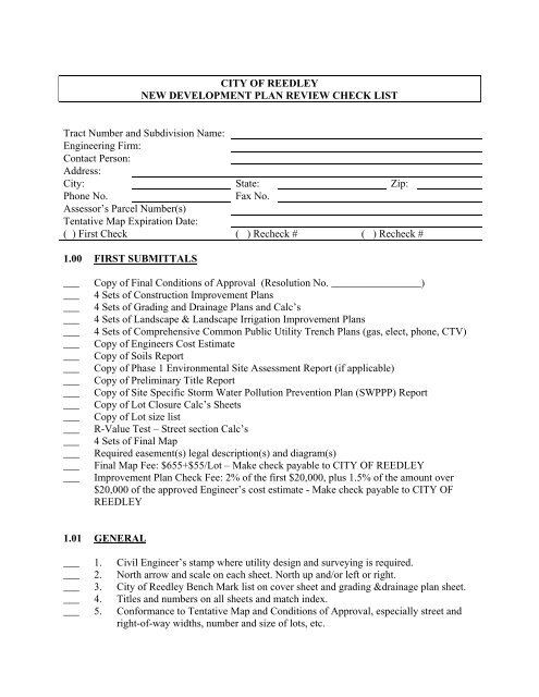
CITY OF REEDLEYNEW DEVELOPMENT PLAN REVIEW CHECK LISTTract Number and Subdivision Name:Engineering Firm:Contact Person:Address:<strong>City</strong>: State: Zip:Phone No.Fax No.Assessor’s Parcel Number(s)Tentative Map Expiration Date:( ) First Check ( ) Recheck # ( ) Recheck #1.00 FIRST SUBMITTALS___________________________________________________Copy <strong>of</strong> Final Conditions <strong>of</strong> Approval (Resolution No. _________________)4 Sets <strong>of</strong> Construction Improvement <strong>Plan</strong>s4 Sets <strong>of</strong> Grading and Drainage <strong>Plan</strong>s and Calc’s4 Sets <strong>of</strong> Landscape & Landscape Irrigation Improvement <strong>Plan</strong>s4 Sets <strong>of</strong> Comprehensive Common Public Utility Trench <strong>Plan</strong>s (gas, elect, phone, CTV)Copy <strong>of</strong> Engineers Cost EstimateCopy <strong>of</strong> Soils ReportCopy <strong>of</strong> Phase 1 Environmental Site Assessment Report (if applicable)Copy <strong>of</strong> Preliminary Title ReportCopy <strong>of</strong> Site Specific Storm Water Pollution Prevention <strong>Plan</strong> (SWPPP) ReportCopy <strong>of</strong> Lot Closure Calc’s SheetsCopy <strong>of</strong> Lot size listR-Value Test – Street section Calc’s4 Sets <strong>of</strong> Final MapRequired easement(s) legal description(s) and diagram(s)Final Map Fee: $655+$55/Lot – Make check payable to CITY OF REEDLEYImprovement <strong>Plan</strong> Check Fee: 2% <strong>of</strong> the first $20,000, plus 1.5% <strong>of</strong> the amount over$20,000 <strong>of</strong> the approved Engineer’s cost estimate - Make check payable to CITY OFREEDLEY1.01 GENERAL___ 1. Civil Engineer’s stamp where utility design and surveying is required.___ 2. North arrow and scale on each sheet. North up and/or left or right.___ 3. <strong>City</strong> <strong>of</strong> <strong>Reedley</strong> Bench Mark list on cover sheet and grading &drainage plan sheet.___ 4. Titles and numbers on all sheets and match index.___ 5. Conformance to Tentative Map and Conditions <strong>of</strong> Approval, especially street andright-<strong>of</strong>-way widths, number and size <strong>of</strong> lots, etc.
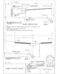
1.02 TITLE SHEET___ 1. Name <strong>of</strong> Tract or Project.___ 2. Tract Number.___ 3. Vicinity Map with north arrow (north up and/or left or right).___ 4. Sheet Index.___ 5. <strong>City</strong> Engineer’s Signature Block.___ 6. Public Works Director Signature Block.___ 7. Alta Irrigation District Manager Signature Block (if applicable).___ 8. Fresno County Public Works Department Signature Block (if applicable).___ 9. Property Owner/Developer Name, Address, Phone Number.___ 10. Design Engineering Firm’s Name, Address, Phone Number.___ 11. Underground Service Alert (USA) reference and Phone Number.___ 12. <strong>City</strong> <strong>of</strong> <strong>Reedley</strong> General Notes.___ 13. Resolution Number (approving project).1.03 SHEET ONE (TITLE SHEET AND/OR SHEET TWO, IF REQUIRED)___ 1. Map showing all streets, utilities, structures, etc. and show improvement plan sheetlayout.___ 2. Drafting symbol legend.___ 3. Typical street sections shown.___ 4. Structural street sections agree with <strong>City</strong> Standard ST-11 (T.I., R-value, AC, AB).___ 5. Curbs shown.___ 6. Right-<strong>of</strong>-way and street widths shown.___ 7. Cross-slope shown – note relative difference <strong>of</strong> and T/C.___ 8. Sidewalk shown.___ 9. Pedestrian paths shown.___ 10. Drainage ways shown.___ 11. Temporary and Permanent bench marks and descriptions.___ 12. List <strong>of</strong> Abbreviations.1.04 DEMOLITION AND ABANDONMENT PLAN (If Required)___ 1. Show existing building(s) and structure(s).___ 2. Existing septic tanks and leach fields shown.___ 3. Existing water wells shown.___ 4. Existing irrigation pipelines shown.___ 5. Existing undersized water and sewer mains shown.___ 6. Existing power poles and overhead utility lines shown.1.05 GRADING PLANS___ 1. Existing elevations and/or contours shown (may be on separate sheet).___ 2. Proposed lot grades.
___ 3. TC elevations at property line extensions.___ 4. TC at grade breaks and curb returns shown.___ 5. TC at storm drain inlets shown.___ 6. Street slopes at centerline shown. (0.2% minimum)___ 7. Lot numbers shown.___ 8. Retaining walls and decorative masonry block walls shown.___ 9. <strong>Plan</strong> and section view <strong>of</strong> typical lot drainage shown, <strong>City</strong> Std <strong>Plan</strong> ST-18A.___ 10. Section <strong>of</strong> typical lot to show property line slope relations, <strong>City</strong> Std <strong>Plan</strong> ST-18B.___ 11. Show grading required for <strong>of</strong>f-site drainage.___ 12. Grading shown between back-<strong>of</strong>-curb or sidewalk and original ground at right-<strong>of</strong>wayline.___ 13. Grading conforms to adjacent properties shown correctly and no adverse effects onfuture development.___ 14. Check on drainage across lot lines and lots to drain to streets.___ 15. Maximum slopes 2:1 or per Soils Report.___ 16. All pads above high water if storm drain plugs. (Surface flows)___ 17. Elevations at rear <strong>of</strong> lots shown.1.06 UTILITY PLANS (1 or 2 sheets)___ 1. Station number on sanitary sewer laterals (in cul-de-sacs, dimension <strong>of</strong>f lot lines atright-<strong>of</strong>-way).___ 2. Water service dimensioned <strong>of</strong>f sanitary sewer or standard detail describing <strong>of</strong>fset.___ 3. Water, sewer, storm drain mains with line sizes and direction <strong>of</strong> flow indicated.___ 4. Appurtenances (fire hydrants, manholes, blow-<strong>of</strong>fs, air release valves, catch basins,street lights, irrigation sleeves, Alta irrigation lines).___ 5. Gate valves.___ 6. Off-site utility work.___ 7. Scale 1”=20” up to 1”=40’, north arrow.___ 8. Irrigation service points for landscaping in the public right-<strong>of</strong>-way.___ 9. Street names.___ 10. Boundaries <strong>of</strong> subdivision.___ 11. Electrical service connection(s) for landscape irrigation system.1.07 STREETS (<strong>Plan</strong> and Pr<strong>of</strong>ile)A. <strong>Plan</strong> Views___ 1. Wheelchair ramps shown and referenced to <strong>City</strong> Std <strong>Plan</strong>s.___ 2. Radius <strong>of</strong> curvature, central angle, and length shown on all street curves.___ 3. Curb curve data given; central angle, length, and radius to <strong>City</strong> Std <strong>Plan</strong>s.___ 4. Scale: 1”=20’ up to 1”=40’.___ 5. Cul-de-sac radius per <strong>City</strong> Std. <strong>Plan</strong>s.___ 6. Right-<strong>of</strong>-way and street width dimensions shown.___ 7. Centerline stationing at 100’ and at BC and EC curves.___ 8. Lot/parcel lines and numbers/letters shown.___ 9. Cul-de-sac cross slopes from high point or gutter lip min. 2% and max. 5%.
_________________________________________________________10. Valley gutters (in-fill projects only) – show flow lines at center <strong>of</strong> street.11. Stationing at all drainage structures shown.12. Top <strong>of</strong> curb elevation given at all drain structures.13. Drainage easements shown and dimensioned.14. Location <strong>of</strong> underground pipes and utilities shown.15. Station and <strong>of</strong>f-set location <strong>of</strong> fire hydrants (at 300 feet o.c.).16. Street monuments shown.17. Pedestrian paths shown. Basic grades shown.18. Street names shown (include direction N,S,W,E).19. Stations and elevations street intersections shown (include station equations).20. All notes and symbols standard and conforming to legend.21. All existing utility poles with identification number, manholes, valves, signs, mailboxes, trees, etc., shown. Indicate those to be removed, relocated or adjusted tograde.22. Continuation and cross streets properly referenced.23. Project limits and <strong>City</strong> limits shown.24. <strong>City</strong> Standard knuckles used.25. Barricades shown in proper location.26. Handicap ramps shown and referenced to <strong>City</strong> Standard <strong>Plan</strong>s.27. Driveway locations and widths shown, reference <strong>City</strong> Standard <strong>Plan</strong>s.28. Streets are being overlayed in areas where newly services excessively cut theexisting pavement.B. Medians (if required)___ 1. Irrigation and electrical service shown.___ 2. Approved landscape plans for medians.___ 3. Median curbs per <strong>City</strong> Standard <strong>Plan</strong>s. (Curb height for pavement = 8”).___ 4. Median island nose treatment (decorative reinforced stamped concrete).___ 5. Irrigation street crossover with landscape median, sleevend detail, <strong>City</strong> Std. L-10.___ 6. Lane storage length and design per Caltrans Standards.C. Pr<strong>of</strong>iles___ 1. Vertical curves designed for proper speeds per Highway Design Manual.___ 2. Minimum vertical curve lengths observed (50’).___ 3. Vertical scale 1”=2’ or 4’.___ 4. Vertical curve, used for grade breaks greater than 1%.___ 5. In cul-de-sac, show pr<strong>of</strong>iles @centerline from end <strong>of</strong> TC pr<strong>of</strong>ile through the radiuspoint to TC at end <strong>of</strong> cul-de-sac (dashed line).___ 6. 2% street cross-slope grade from centerline to gutter lip observed on all streets.___ 7. 0.20% minimum gutter grade slope observed on all streets at curb.___ 8. 0.35’ minimum fall around curb returns on all streets.___ 9. All underground pipes and utilities shown; storm drain, water and sewer.___ 10. Existing ground at centerline shown.___ 11. Finished grade pr<strong>of</strong>ile for top <strong>of</strong> curb shown.___ 12. Centerline pr<strong>of</strong>iles <strong>of</strong> intersecting streets shown on to their point <strong>of</strong> intersection.
___ 13. Off-tract pr<strong>of</strong>ile to catch point shown where road is constructed to subdivisionboundary.___ 14. Centerline stations and elevations shown at all BVC, EVC, PIVC, grade breaks, lowpoints and high points.___ 15. All slopes in pr<strong>of</strong>ile shown.___ 16. Show all utility crossings with clearance indicated when closer than 15”.___ 17. Manhole and drop inlet and flow-line elevations shown.1.08 SANITARY SEWER___ 1. System in agreement with tentative map and master plan.___ 2. Design conforms to <strong>City</strong> standards.___ 3. Size <strong>of</strong> proposed lines shown.___ 4. Adequate cover; 42” min. to finished grade – 2’ min. to subgrade, ductile iron pipeor engineered alternatives if shallower. (See <strong>City</strong> Std. <strong>Plan</strong> ST-9)___ 5. Clearance with water main per <strong>City</strong> Standard <strong>Plan</strong> W-6.___ 6. Size, slope, length between structures, and type <strong>of</strong> pipe (SDR 35).___ 7. Points <strong>of</strong> Connection to existing facilities.___ 8. Extension <strong>of</strong> lines to subdivision boundaries.___ 9. Sewer line to be located per <strong>City</strong> Standard <strong>Plan</strong> ST-25.___ 10. Curves allowed within 80% <strong>of</strong> recommendations <strong>of</strong> pipe manufacturer. Show curvedata or <strong>of</strong>fsets if concentric with centerline.___ 11. On all curves where short pipe lengths are used, indicate clearly on plans.___ 12. Rim and pipe invert elevations on manholes shown.___ 13. Station given for manholes.___ 14. Size <strong>of</strong> existing lines shown.___ 15. Pipe types allowed, SDR 35 (D.I.P. if cover requires it).___ 16. 300’ maximum distance manhole to manhole.___ 17. Minimum 2 fps velocity.___ 18. 0.10’ drop around corner through manhole.___ 19. Sewer lines crossing water are in conformance with Department <strong>of</strong> HealthRequirements. <strong>Plan</strong>s must specify length <strong>of</strong> section and type <strong>of</strong> piping at crossing.___ 20. Bolted manhole covers for any <strong>of</strong>f street manholes.___ 21. Check sanitary calculations.___ 22. Laterals shown in plan and 10’ center to center from water services and 3’ belowwater if crossing. (follow Health Department diagram)___ 23. Special approval areas shall be noted in pr<strong>of</strong>ile (less than minimum cover andclearance.___ 24. Cleanout on mains where temporary phasing exists and run does not exceed 250’ and3 services. Manhole and stub when temporary stop exceeds 250’ or more than 3services are going to be installed.___ 25. 8” minimum sewer main size (may use 6” within cul-de-sac street if adequate cover).___ 26. Manhole sizes, 48” or 60” (per <strong>City</strong> Standard <strong>Plan</strong> S-2 or S-3).
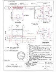
1.09 DRAINAGEA. Hydrology – Hydraulics___ 1. Calculations per <strong>City</strong> Standards and based on 5-year storm with minimum velocity<strong>of</strong> 2 fps.___ 2. Calculations shall include the following: HGL, FL, EL, Q, A, S, V, freeboard atstructures, structure losses, and tail-water assumptions (5 year and 100 year).___ 3. Adequacy <strong>of</strong> in-tract and <strong>of</strong>f-tract drainage system verified.___ 4. All starting water surface calculations adequately verified.___ 5. Drainage map showing street system, existing and proposed drainage system, slopearrows, tributary sub-areas, peak flow in all pipes (scale: 1” = 100’).___ 6. All pipe in tributary areas labeled to correspond with calculations.___ 7. System in agreement with tentative map Conditions <strong>of</strong> Approval.B. Easements___ 1. Off-tract drainage improvements (plan and pr<strong>of</strong>ile) and accompanying easementsshown. Off-tract <strong>of</strong>fers <strong>of</strong> dedication for drainage easements submitted for review.___ 2. Off-tract work to be done but no easement requirements. Right <strong>of</strong> entry submittedfor review. (if applicable)___ 3. Easement widths indicated on plans.___ 4. Easements across lots are not permitted.C. Pipe___ 1. Size, slope, length between structures, type and class <strong>of</strong> thickness <strong>of</strong> pipe shown inpr<strong>of</strong>iles (15” minimum).___ 2. Reinforced concrete, R.G.R.C.P., PVC (SDR35) “Cast-In-Place is not allowed”.___ 3. Trunk line locations per <strong>City</strong> Std <strong>Plan</strong> ST-25.___ 4. 3’ minimum cover over pipe to finish grade unless special design and calcssubmitted.___ 5. Curve radii allowed to within 80% <strong>of</strong> pipe manufacture’s recommendations.___ 6. All curve data at centerline <strong>of</strong> pipe shown unless concentric with street then <strong>of</strong>fsetsallowed.___ 7. Elevations, slopes and distances all mathematically correct.___ 8. Match hydraulic/hydrology calculations.___ 9. Drainage provided for frontage along subdivision but separated by a block wall (thisincludes areas designated in <strong>City</strong>’s L&LMD No. 1).E. Temporary and Permanent Storm Drain Basins___ 1. Run<strong>of</strong>f and volume calculations per <strong>City</strong> Design Guidelines.___ 2. Groundwater level shown on basin section.___ 3. Basin bottom 10’ above water table.___ 4. Outfall protection using rip-rap (8” minimum) required and flared end section ontemporary basins and headwalls on permanent basins.___ 5. Chain link fence around basins required with landscaping.___ 6. Ramp at 15% maximum required, See <strong>City</strong> Standard <strong>Plan</strong> SD-5.
___ 7. Basin requires minimum 8’ wide access maintenance road around basin perimeter.___ 8. Required easements (if applicable).___ 9. Percolation rate calculations for retention basin.___ 10. Infiltration test results turned in for percolation basin.___ 11. Basin side slope per <strong>City</strong> Storm Drain Master <strong>Plan</strong> recommendations.___ 12. Landscape irrigation system design (if applicable).___ 13. Pumping system for permanent basin (if applicable).1.10 WATER MAINS___ 1. System in agreement with tentative map Conditions <strong>of</strong> Approval.___ 2. Design conforms to <strong>City</strong> standards.___ 3. Size – 8” minimum.___ 4. Gate valves as required to control system.___ 5. Fire hydrants – locations reviewed and approved by <strong>City</strong> Fire Chief.___ 6. Cover 36” minimum to finished grade.___ 7. Proper separation from sewer mains and storm drain line (10’ minimum).___ 8. Location – per <strong>City</strong> Standard <strong>Plan</strong> ST-25.___ 9. Water mains kept in street right-<strong>of</strong>-way (easements discouraged)___ 10. Crossing with sewer mains, storm drain, irrigation or other non potable laterals meethealth standards (<strong>City</strong> Standard <strong>Plan</strong> W-6.___ 11. Length and size <strong>of</strong> pipe shown in pr<strong>of</strong>ile (indicate all changes in class <strong>of</strong> pipeexceeding CL 150).___ 12. Length shown as distances between crosses and tees.___ 13. Invert elevations shown at grade breaks.___ 14. Top <strong>of</strong> curb at fire hydrant locations shown.___ 15. Size <strong>of</strong> all exiting lines shown.___ 16. Curve radii allowed to within 80% <strong>of</strong> pipe manufacture’s recommendations. Curvedata at centerline <strong>of</strong> pipe shown unless concentric with street then <strong>of</strong>fsets acceptable.___ 17. Air valves and blow-<strong>of</strong>fs behind sidewalks.___ 18. Fire hydrants at back <strong>of</strong> cul-de-sacs for terminating water lines (in lieu <strong>of</strong> blow-<strong>of</strong>f).___ 19. Point <strong>of</strong> connection(s) to existing facilities (system looped).___ 20. At points <strong>of</strong> future extension install temporary blow-<strong>of</strong>f with valve (<strong>City</strong> Std W-5)___ 21. Lines extended to tract boundaries and along frontage.___ 22. House services shown on plan and stationed.___ 23. Fire hydrants maximum spacing 300’.1.11 STREET LIGHTING___ 1. Shown at 1” = 40’ or 1”= 100’ plan scale.___ 2. Type-15, Layout shown per <strong>City</strong> Standard <strong>Plan</strong> ST-24C.___ 3. Historic light standard, Layout shown as per Holophane (manufacture’srecommendation)___ 4. Wattage, arm length, and pole heights shown on plans.___ 5. Point <strong>of</strong> Connection(s) shown on plans.___ 6. Conduit locations shown on plans.___ 7. Type-15 Street light Standard identification numbers, to be assigned by P.G.&E.
1.12 STREET STRIPING PLAN___ 1. Shown on 1”=40’ scale.___ 2. Striping Legend shown on <strong>Plan</strong> Sheet.___ 3. References to Caltrans Detail number and Standard Drawing sheet.___ 4. Lengths, widths and color <strong>of</strong> strips noted on Striping <strong>Plan</strong> sheet.___ 5. Regulatory, warning and street name sign locations and noted on plan sheet.___ 6. Existing striping to be removed shown and noted on Striping <strong>Plan</strong> sheet.___ 7. Existing traffic signs to be removed or relocated noted and shown on plan sheet.___ 8. <strong>City</strong> Engineer’s Signature Block.___ 9. Public Works Director Signature Block.1.13 LANDSCAPE AND IRRIGATION PLAN___ 1. Shown on 1”=20’ scale.___ 2. Electrical service connection point(s) for irrigation system shown on plan.___ 3. Water connection point(s) for irrigation system shown on plan.___ 4. All irrigation laterals and main lines 2” diameter and less shall be schedule 40 PVC.___ 5. Electric controller location(s) shown on plan.___ 6. Property and/or right-<strong>of</strong>-way lines and planting easements shown on plan.___ 7. Landscape and irrigation legend shown on plans.___ 8. Typical sight distance requirements at intersections (<strong>City</strong> Std <strong>Plan</strong> L-12).___ 9. Public Works Director Signature Block.___ 10. Community Service Director Signature Block1.14 ENGINEER’S COST ESTIMATE___ 1. Verify that unit cost compare with <strong>City</strong> standard costs.___ 2. Verify quantities <strong>of</strong> all public improvement items.___ 3. <strong>Review</strong> with plans to determine if there are missing items.___ 4. 10% minimum contingency required.___ 5. Grading quantities (cubic yards) shown for cut and fills – lump sums not acceptable.___ 6. Driveways included as a separate item.___ 7. Sidewalks on a square foot and not included in curb and gutter item.___ 8. When resubmitted, verify that all changes in plans are reflected in the estimate.
C:\Documents and Settings\Mike.CITYOFREEDLEY\Desktop\REVIEW CHECK LIST.doc