
You also want an ePaper? Increase the reach of your titles
YUMPU automatically turns print PDFs into web optimized ePapers that Google loves.
The winding direction of a triangle indicates the direction in which the vertices are ordered. It can either beclockwise or counter clockwise.A leading vertex is the first vertex in a sequence of three vertices.1.2 Shader StagesThe <strong>Direct3D</strong> <strong>10</strong> pipeline contains 3 programmable-shader stages (shown as the rounded blocks in thepipeline functional diagram):• Vertex Shader Stage• Geometry Shader Stage• Pixel Shader StageEach shader stage exposes its own unique functionality, built on the shader model 4.0 common shader core.1.2.1 Vertex Shader StageThe vertex shader stage processes vertices from the input assembler, performing per-vertex operations suchas transformations, skinning, morphing, and per-vertex lighting. Vertex shaders always operate on a singleinput vertex and produce a single output vertex. The vertex shader stage must always be active for thepipeline to execute. If no vertex modification or transformation is required, a pass-through vertex shadermust be created and set to the pipeline.Each vertex shader input vertex can be comprised of up to 16 32-bit vectors (up to 4 components each) andeach output vertex can be comprised of as many as 16 32-bit 4-component vectors. All vertex shaders musthave a minimum of one input and one output, which can be as little as one scalar value.The vertex shader stage can consume two system generated values from the input assembler: VertexID andInstanceID (see System Values and Semantics). Since VertexID and InstanceID are both meaningful at avertex level, and IDs generated by hardware can only be fed into the first stage that understands them, theseID values can only be fed into the vertex shader stage.Vertex shaders are always run on all vertices, including adjacent vertices in input primitive topologies withadjacency. The number of times that the vertex shader has been executed can be queried from the CPUusing the VSInvocations pipeline statistic.The vertex shader can perform load and texture sampling operations where screen-space derivatives are notrequired (using HLSL intrinsic functions samplelevel, samplecmplevelzero, samplegrad).1.2.2 Geometry Shader StageThe geometry shader runs application-specified shader code with vertices as input and the ability togenerate vertices on output. Unlike vertex shaders, which operate on a single vertex, the geometry shader'sinputs are the vertices for a full primitive (two vertices for lines, three vertices for triangles, or single vertexfor point). Geometry shaders can also bring in the vertex data for the edge-adjacent primitives as input (anadditional two vertices for a line, an additional three for a triangle).The geometry shader stage can consume the SV_PrimitiveID System Value that is auto-generated by the IA.This allows per-primitive data to be fetched or computed if desired.SIGGRAPH 2006 2 – 6 Course 3, GPU Shading and Rendering
6 ConclusionThe decision of using a technology or a design methodinstead of another one mainly depends on the parameter(s)we want to optimize. In case of connectors, the focusis usually set to the transmission quality. This term addressestransmission rate and also resource requirements.Additional (non measurable) parameters such as presenceof timing constraints or flexibility in the interface implementationcan be taken into account, too.In this paper we have presented an asynchronous,delay-insensitive approach for connecting two independentsynchronous modules. The main advantages of thisapproach are (i) the maximization of the data transfer rateper interconnect wire and (ii) the absence of timing constraintswith respect to the clock domains. The proposedasynchronous connector thus well suits both for highspeedintra-chip communication and for inter-chip communication.Future work is going towards the development of ageneric configurable asynchronous connector that supportsboth serial and parallel transmission. This mixedapproach should provide a new configuration opportunityfor a system designer to adjust the trade-off between datatransfer rate and resource requirements.7 AcknowledgementsThis work has been partially funded by the FIT-IT [embeddedsystems initiative of the Austrian Federal Ministryof Transport, Innovation, and Technology] and managedby Eutema and the Austrian Research Agency FFG withinprojects COMPASS [3] (contract 809444) and ExTraCT(contract 8<strong>10</strong>834).We would especially like to thank Martin Delvai andPeter Tummeltshammer for valuable support and interestingdiscussions during integration of the SPEAR microcontroller.References[1] Flexray Communications Systems – ProtocolSpecification Version 2.1, available athttp://www.flexray.com. FlexRay Consortium,2005.[2] Daniel M. Chapiro. Globally-Asynchronous Locally-Synchronous Systems. PhD thesis, Stanford University,October 1984.[3] COMPASS. Component Based Automotive SystemSoftware. http://www.infosys.tuwien.ac.at/compass.[4] Martin Delvai. SPEAR Handbuch. Technical report,Treitlstr. 3/3/182-1, <strong>10</strong>40 Vienna, Austria, 2002.[5] Martin Delvai and Andreas Steininger. Asynchronouslogic design - from concepts to implementation.In The 3rd International Conference on Cyberneticsand Information Technologies, Systems andApplications, pages 81–86, 2006.[6] Scott Hauck. Asynchronous design methodologies:An overview. Proceedings of the IEEE, 83(1):69–93,January 1995.[7] M. Horauer, F. Rothensteiner, M. Zauner, E. Armengaud,A. Steininger, H. Friedl, and R. Pallierer.An FPGA based SoC Design for Testing EmbeddedAutomotive Communication Systems employing theFlexRay Protocol. In Proceedings of the Austrochip2004 Conference, pages 119–125, September 2004.[8] Xin Jia and Ranga Vemuri. Using GALS architectureto reduce the impact of long wire delay onFPGA performance. In Ting-Ao Tang, editor, ASP-DAC, pages 1260–1263. ACM Press, 2005.[9] A. J. Martin. The limitations to delay-insensitivity inasynchronous circuits. Technical report, CaliforniaInstitute of Technology, 1990.[<strong>10</strong>] Anthony J. McAuley. Four state asynchronous architectures.IEEE Trans. Computers, 41(2):129–142,1992.[11] Jens Muttersbach, Thomas Villiger, and WolfgangFichtner. Practical design of globally-asynchronouslocally-synchronous systems. In Proc. InternationalSymposium on Advanced Research in AsynchronousCircuits and Systems, pages 52–59, April 2000.[12] Jens Muttersbach, Thomas Villiger, Hubert Kaeslin,Norbert Felber, and Wolfgang Fichtner. Globallyasynchronouslocally-synchronous architectures tosimplify the design of on-CHIP systems. In Proc.12th International ASIC/SOC Conference, pages317–321, September 1999.[13] Mehrdad Najibi, Kamran Saleh, Mohsen Naderi,Hossein Pedram, and Mehdi Sedighi. Prototypingglobally asynchronous locally synchronous circuitson commercial synchronous FPGAs. In IEEE InternationalWorkshop on Rapid System Prototyping,pages 63–69. IEEE Computer Society, 2005.[14] Jens Sparso and Steve Furber. Principles of AsynchronousCircuit Design - A Systems Perspective.Kluwer Academic Publishers, Norwell, MA, USA,2001.[15] I. E. Sutherland. Micropipelines (the turing awardlecture). Comm.A.C.M., 32(6):720–738, June 1989.[16] George S. Taylor, Simon W. Moore, Robert D.Mullins, and Peter Robinson. Point to point GALSinterconnect. In ASYNC, pages 69–75. IEEE ComputerSociety, 2002.[17] Hiroaki Terada, Souichi Miyata, and Makoto Iwata.DDMP’s: Self-timed super-pipelined data-drivenmultimedia processors. Proceedings of the IEEE,87(2):282–296, February 1999.
esource. There is no limit to the number of constant buffers an application can create. By organizingconstants into buffers by frequency of update and usage, the amount of bandwidth required to updateconstants to accommodate all shaders can be significantly reduced.1.3.1 Integer and Bitwise SupportThe common shader core provides a full set of IEEE-compliant 32-bit integer and bitwise operations. Theseoperations enable a new class of algorithms in graphics hardware - examples include compression andpacking techniques, FFT's, and bitfield program-flow control.The int and uint data types in <strong>Direct3D</strong> <strong>10</strong> HLSL map to 32 bit integers in hardware.Differences between <strong>Direct3D</strong> 9 and <strong>Direct3D</strong> <strong>10</strong>:In <strong>Direct3D</strong> 9 stream inputs marked as integer in HLSL were interpreted as floating-point. In <strong>Direct3D</strong> <strong>10</strong>,stream inputs marked as integer are interpreted as a 32 bit integer.In addition, boolean values are now all bits set or all bits unset. Data converted to bool will be interpretedas TRUE if the value is not equal to 0.0f (both positive and negative zero are allowed to be FALSE) andFALSE otherwise.1.3.2 Bitwise operatorsThe common shader core supports the following bitwise operators:Operator Function~ Logical Not> Right Shift&Logical And| Logical Or^&&=Logical XorLeft shift Equal>>= Right Shift Equal&= And Equal|= Or Equal^= Xor EqualBitwise operators are defined to operate only on Int and UInt data types. Attempting to use bitwiseoperators on float, or struct data types will result in an error. Bitwise operators follow the same precedenceas C with regard to other operators.1.3.3 Binary CastsCasting operation between an int and a float type will convert the numeric value following C rules fortruncation of int data types. Casting a value from a float, to an int, back to a float result in a lossyconversion according to defined precision of the target.SIGGRAPH 2006 2 – <strong>10</strong> Course 3, GPU Shading and Rendering
Binary casts may also be performed using HLSL intrinsic function. These cause the compiler to reinterpretthe bit representation of a number into the target data type. Here are a few examples:asfloat() //Input data is aliased to floatasint()//Input data is aliased to intasuint() //Input data is aliased to Uint1.4 Shader Constant VariablesIn <strong>Direct3D</strong> <strong>10</strong>, HLSL constant variables are stored in one or more buffer resources in memory.Shader constants can be organized into two types of buffers: constant buffers (cbuffers) and texture buffers(tbuffers). Constant buffers are optimized for shader-constant-variable usage: lower-latency access andmore frequent update from the CPU. For this reason, additional size, layout, and access restrictions apply tothese resources. Texture buffers utilize the texture access pipe and can have better performance forarbitrarily indexed data. Regardless of which type of resource you use, there is no limit to the number ofcbuffers or tbuffers an application can create.Declaring a cbuffer or tbuffer in HLSL looks very much like a structure declaration in C. Define a variablein a constant buffer similar to the way a struct is defined:cbuffer name{variable declaration;...};where• name - the constant buffer name• variable declaration - any HLSL or effect non-object declaration (except texture and sampler)The register modifier can be applied to a cbuffer/tbuffer namespace, which overrides HLSL autoassignment and causes a user specified binding of the named cbuffer/tbuffer to a given constantbuffer/texture slot.Differences between <strong>Direct3D</strong> 9 and <strong>Direct3D</strong> <strong>10</strong>:Unlike the auto-allocation of constants in <strong>Direct3D</strong> 9 which did not perform packing and instead assignedeach variable to a set of float4 registers, HLSL constant variables follow packing rules in <strong>Direct3D</strong> <strong>10</strong>.A cbuffer or tbuffer definition is not a declaration because there is no type checking done, the definitiononly acts as a mechanism for naming a constant/texture buffer. It is similar to a namespace in C. Allvariables defined in constant and texture buffers must have unique names within their namespace. Anyvariable without a namespace defined, is in the global namespace (called the $Globals constant buffer,which is defined in all shaders). The register specifier can be used for assignment within a cbuffer ortbuffer, in which case the assignment relative to that cbuffer/tbuffer namespace. The register specificationoverrides the packing derived location.SIGGRAPH 2006 2 – 11 Course 3, GPU Shading and Rendering
1.4.1 Organizing Constant VariablesTo make efficient use of bandwidth and maximize performance, the application can organize its constantvariables into buffers by frequency of update and usage. For instance, data that needs to be updated perobject, should be grouped into a different buffer than data used by all objects and materials in the scene.Figure 4: Binding Constant Buffers to ShadersThe first shader uses only two of the constant buffers. The second shader may use the same or differentconstant buffers.As another example:cbuffer myObject{float4x4 matWorld;float3 vObjectPosition;int arrayIndex;}cbuffer myScene{float3 vSunPosition;float4x4 matView;}This example declares two constant buffers and organizes the data in each based on their frequency ofupdate: data that needs to be updated on a per-object basis (like a world matrix) is grouped into myObjectwhich could be updated for each object. This is separate from data that characterizes a scene and istherefore likely to be updated much less often (when the scene changes).1.4.2 Constant BuffersA shader constant buffer is a specialized buffer resource. A single constant buffer can hold up to 4096 4-channel 32-bit elements. As many as 16 constant buffers can be bound to a shader stage simultaneously.A constant buffer is designed to minimize the overhead of setting shader constants. The <strong>Direct3D</strong><strong>10</strong> Effectssystem will manage updating of tbuffers and cbuffers for you. Alternatively, the buffer can be updateddirectly by the application via API calls: Map with D3D<strong>10</strong>_MAP_WRITE_DISCARD, orUpdateSubresource. The application can also copy data from another buffer (including a buffer used as arender target or stream out target) into a CB. A constant buffer is the only resource that does not use a viewto bind it to the pipeline, therefore, you cannot use a view to reinterpret the data.SIGGRAPH 2006 2 – 12 Course 3, GPU Shading and Rendering
You can store up to 4096 4-component values in each constant buffer, and you can bind up to 16 constantbuffers to a shader at the same time.1.4.3 Texture BuffersA texture buffer is a buffer of shader constants that is read from texture loads (as opposed to a buffer load).Texture loads can have better performance for arbitrarily indexed data than constant buffer reads.Define a variable in a texture buffer similarly to a constant buffer:tbuffer name{variable declaration;...};where• name - the texture buffer name• variable declaration - any HLSL or effect non-object declaration (except texture or sampler)2. ResourcesA resource is an area in memory that can be accessed by the <strong>Direct3D</strong> pipeline. In order for the pipeline toaccess memory efficiently, data that is provided to the pipeline (such as input geometry, shader resources,textures etc) must be stored in a resource. There are two types of resources from which all <strong>Direct3D</strong>resources derive: a buffer or a texture.Each application will typically create many resources. Examples of resource include: vertex buffers, indexbuffer, constant buffer, textures, and shader resources. There are several options that determine howresources can be used. You can create resources that are strongly typed or typeless; you can controlwhether resources have both read and write access; you can make resources accessible to only the CPU,GPU, or both. Naturally, there will be speed vs. functionality tradeoff - the more functionality you allow aresource to have, the less performance you should expect.Since an application often uses many textures, <strong>Direct3D</strong> also introduces the concept of a texture array tosimplify texture management. A texture array contains one or more textures (all of the same type anddimensions) that can be indexed from within an application or by shaders. Texture arrays allow you to use asingle interface with multiple indexes to access many textures. You can create as many texture arrays tomanage different texture types as you need.Once you have created the resources that your application will use, you connect or bind each resource tothe pipeline stages that will use them. This is accomplished by calling a bind API, which takes a pointer tothe resource. Since more than one pipeline stage may need access to the same resource, <strong>Direct3D</strong> <strong>10</strong>introduces the concept of a resource view. A view identifies the portion of a resource that can be accessed.You can create m views or a resource and bind them to n pipeline stages, assuming you follow bindingrules for shared resource (the runtime will generate errors at compile time if you don't).A resource view provides a general model for access to a resource (textures, buffers, etc.). Because you canuse a view to tell the runtime what data to access and how to access it, resource views allow you createtypeless resources. That is, you can create resources for a given size at compile time, and then declare thedata type within the resource when the resource gets bound to the pipeline. Views expose many newSIGGRAPH 2006 2 – 13 Course 3, GPU Shading and Rendering
capabilities for using resources, such as the ability to read back depth/stencil surfaces in the shader,generating dynamic cubemaps in a single pass, and rendering simultaneously to multiple slices of a volume.2.1 Resource TypesAll resources used by the <strong>Direct3D</strong> pipeline derive from two basic resource types:• a buffer resource• a texture resourceA buffer resource essentially contains an array of elements (similar to an array in C++).Textures, on the other hand, can be more complex: the data in a texture resource is made up of one or moresubresources which are organized into arrays. Unlike buffers, textures can be filtered by texture samplers asthey are read by shader units.There are some restrictions for what types of resource can be bound to particular pipeline stages. This isexplained in below Resource Types and Pipeline stages. Most resources can be created as untyped;however, its memory interpretation must provided when the resource is bound to the pipeline. For example,when the resource is bound as a shader resource, a view must be provided which describes how to interpretthe resource.2.1.1 Buffer ResourcesA buffer resource essentially contains an array of elements (similar to an array in C++). A buffer can bevisualized like this:Figure 5: Buffer Resource ArchitectureThere are 5 elements shown in Figure 5, therefore this buffer can store up to 5 elements of data. The size ofeach element in a buffer is dependent on the type of data that is stored in that element, each elements has adata format defined by DXGI_FORMAT. This means you could create a buffer whose elements are all thesame size or a buffer whose elements are each a different size. Furthermore, the runtime allows you toeither format each element when the resource is created or create an unstructured buffer (in this case youneed to know the buffer size to create).The u vector is a 1D vector that is used to look up the elements in the array. This could have been called anindex, but you will see when you look at the texture resource, how this index gets extended to two or threedimensions (where u, v, and w will be used to a texture resource).When you create a structured buffer, you define the type (and therefore) size of each element at resourcecreation time. This allows the runtime to perform type checking when the resource is created. For anunstructured buffer, you must provide the format of the elements for an unstructured buffer (includingelement types, element offsets and an overall stride) when the unstructured buffer is bound to the graphicspipeline type. This allows the runtime to type check an unstructured buffer when the resource is bound.SIGGRAPH 2006 2 – 14 Course 3, GPU Shading and Rendering
When the buffer is bound to the graphics pipeline, its memory interpretation must be provided as a DXGIformat. This describes types and offsets for the element(s) in the resource.A buffer cannot be filtered, and it does not contain multiple miplevels, multiple subresources, ormultisamples.A Vertex Buffer ResourceA vertex buffer stores per-vertex data such as position, texture coordinates, normals, etc. This data will beassembled into primitives by the IA stage, and streamed into a vertex shader. To see the data that must bestored in a vertex buffer, look at the vertex shader input declaration that will use the data. For example,here is the vertex shader input declaration for the BasicHLSL sample.VS_OUTPUT RenderSceneVS( float4 vPos : POSITION,float3 vNormal : NORMAL,float2 vTexCoord0 : TEXCOORD0,uniform int nNumLights,uniform bool bTexture,uniform bool bAnimate )This vertex shader function takes six input parameters. The first three parameters are per-vertex data whichcomes from the vertex buffer. The last three input parameters are uniform inputs which means that they donot vary per-vertex. Uniform inputs are generally defined once like a #define, and do not need to beincluded in the vertex buffer.A vertex buffer stores data for each of the per-vertex elements. Conceptually it can be viewed like this.Figure 6: Vertex Buffer Data OrganizationThis vertex buffer has enough space allocated for eight vertices. The data for each vertex is made up ofthree elements (labeled p for position, n for normal, and t for texture coordinates). The three elements areshown in the expanded view. Each of the vertices (labels 1-8) in Figure 6 contains these three elements. Allvertex buffers contain a series of vertices; each vertex contains one of more elements. Every vertex in avertex buffer has an identical data structure to every other vertex.To access data from a vertex buffer you need to know which vertex to access and these other bufferparameters:• Offset - the number of bytes from the start of the buffer to the first vertex data. The offset needs tobe supplied to the API when the buffer is bound to the pipeline with IASetVertexBuffers.• BaseVertexLocation - the number of bytes from the offset to the first vertex data used by theappropriate Draw call.SIGGRAPH 2006 2 – 15 Course 3, GPU Shading and Rendering
An Index Buffer ResourceAn index buffer is a buffer that contains a sequential set of indices. Each index is used to look up a vertexin a vertex buffer. Using an index buffer with one or more vertex buffers to supply data to the IA stage iscalled indexing.An index buffer stores index data. It is simpler than a vertex buffer because it can only store one type ofdata, that is, integer indices. Conceptually an index buffer can be viewed like this.Figure 7: Index Buffer Data OrganizationThe sequential indices stored in an index buffer are located with the following parameters:• Offset - the number of bytes from the start of the buffer to the first vertex data. The offset needs tobe supplied to the API when the buffer is bound to the pipeline with IASetIndexBuffer.• StartIndexLocation - the number of bytes from the offset to the first vertex data used by theappropriate Draw call (see Executing the IA Stage).• IndexCount - the number of indices to render.An index buffer contains 16-bit or 32-bit indices.A buffer created with the D3D<strong>10</strong>_BIND_CONSTANT_BUFFER flag can be used to store shader constantdata. Constant buffers must be created with type DXGI_FORMAT_R32G32B32A32_TYPELESS. Thesize of a constant buffer is restricted to hold a maximum of 4096 elements.A buffer created with the D3D<strong>10</strong>_BIND_SHADER_RESOURCE flag can be used as a shader resourceinput, accessed in the shader via the Load() method. The buffer must be bound at one of the available 128slots for input resources, by first creating the appropriate shader resource view.A buffer created with the D3D<strong>10</strong>_BIND_SHADER_RESOURCE flag can be used to store the results ofthe Stream Output stage. There are two types of bindings available for stream output buffers, one that treatsa single output buffer as a multiple-element buffer (array-of-structures), while the other permits multipleoutput buffers each treated as single-element buffers (structure-of-arrays). If the resource also has theD3D<strong>10</strong>_BIND_VERTEX_BUFFER flag specified, the resource may also be used with DrawAuto.2.1.2 Texture ResourcesA texture resource is a structured collection of data designed to store texture data. The data in a textureresource is made up of one or more subresources which are organized into arrays and mipchains. Unlikebuffers, textures can be filtered by texture samplers as they are read by shader units. The type of resourceimpacts how the texture is filtered - for example, TextureCubes are filtered across edges.• Texture1D and Texture1DArray ResourceSIGGRAPH 2006 2 – 16 Course 3, GPU Shading and Rendering
• Texture2D and Texture2DArray Resource• Texture3D ResourceTexture1D and Texture1DArray ResourceLike the buffer resource, a Texture1D contains a 1D array of elements. Unlike the buffer resource, atexture1D resource is filtered and may contain one or more mip levels. The 1D texture resource looks likethis:Figure 8: Texture1D Resource ArchitectureFigure 8 illustrates a Texture1D resource with 3 mip levels. The top-most mip level is the largest level;each successive level is a power of 2 (on each side) smaller. In this example, since the top-level texturewidth is 5 elements, there are two mip levels before the texture width is reduced to 1. Each element in eachmip level is addressable by the u vector (which is commonly called a texture coordinate).Each element in each mip level contains a single texel, or texture value. The data type of each element isdefined by the texel format which is once again a DXGI_FORMAT value. A texture resource may be typedor typeless at resource-creation time, but when bound to the pipeline, its interpretation must be provided ina view.A Texture1DArray resource is a homogenous array of 1D textures. It looks like an array of 1D textures.Figure 9: Texture1DArray Resource ArchitectureThis texture array contains three textures. Each of the three textures has a texture width of 5 (which is thenumber of elements in the 1st layer). Each texture also contains a 3 layer mip-map.All texture arrays in <strong>Direct3D</strong> are a homogenous array of textures; this means that every texture in a texturearray must have the same data format and size (including texture width and number of miplevels). You maycreate texture arrays of different sizes, as long as all the textures in each array match in size.SubresourcesOne interesting feature with <strong>Direct3D</strong> texture resources (including textures and texture arrays) is that theyare made up of subresources. A subresource is defined as single mip level and texture index. In other words,for a single texture, a subresource is a single mip level. For instance, here is a valid subresource for a 1Dtexture.SIGGRAPH 2006 2 – 17 Course 3, GPU Shading and Rendering
Figure <strong>10</strong>: Texture1D SubresourceA subresource is a texture and mip-level combination. This 1D texture is made up of 3 subresources. For atexture array, a subresource can be extended to an array of single mip levels. Here is an example ofsubresources, within a 2DTextureArray.Figure 11: Texture1DArray SubresourceThis subresource is an array of the top mip level of all three textures in the texture array resource. Youcould have specified any mip level in the subresource. <strong>Direct3D</strong> uses a resource view to access this array oftexture subresources in a texture array.The pipeline uses several objects derived from a Texture1D resource to read data from or write data to.This table shows the types of objects that can be created from texture resources, and where they can bebound to the pipeline:Indexing SubresourcesA texture array can contain multiple textures, each with multiple mip-levels. Each subresource is a singletexture mip-level. When accessing a particular subresource, this is how the subresources are iondexedwithin a texture array, with multiple mip levels.Figure 12: Indexing Subrsources in a Texture1DArrayThe index starts at zero in the first texture in the array, and increments through the mip levels for thattexture. Simply increment the index to go to the next texture.Texture2D and Texture2DArray ResourceA Texture2D resource contains a 2D grid of texels. Each texel is addressable by a u, v vector. Since it is atexture resource, it may contain mip levels, and subresources. A fully populated 2D texture resource lookslike this:SIGGRAPH 2006 2 – 18 Course 3, GPU Shading and Rendering
Figure 13: Texture2D Resource ArchitectureThis texture resource contains a single 3x5 texture with two mip levels.A Texture2D resource is a homogeneous array of 2D textures; that is, each texture has the same data formatand dimensions (including mip levels). It has a similar layout as the Texture1D resource except that thetextures now contain 2D data, and therefore looks like this:Figure 14: Texture2DArray Resource ArchitectureThis texture array contains three textures; each texture is 3x5 with two mip levels.Texture2DArray Resource as a Texture CubeA texture cube is a Texture2DArray that contains 6 textures, one for each face of the cube. A fullypopulated texture cube looks like this:Figure 15: TextureCube Resource ArchitectureA Texture2DArray that contains 6 textures may be read from within shaders with the cube map sampleinstructions, after they are bound to the pipeline with a cube-texture view. Texture cubes are addressedfrom the shader with a 3D vector pointing out from the center of the texture cube.SIGGRAPH 2006 2 – 19 Course 3, GPU Shading and Rendering
Texture3D ResourceA Texture3D resource (also known as a volume texture) contains a 3D volume of texels. Since it is atexture resource, it may contain mip levels. A fully populated Texture3D resource looks like this:Figure 16: Texture3D Resource ArchitectureWhen a Texture3D mip-slice is bound as a rendertarget output, (by creating a rendertarget view), theTexture3D behaves identically to a Texture2DArray with n array slices where n is the depth (3rddimension) of the Texture3D. The particular slice in the Texture3D to render is chosen from the geometryshader stage, by declaring a scalar component of output data as the SV_RenderTargetArrayIndex systemvalue.There is no concept of an array of Texture3D resources; therefore a Texture3D subresource is a single miplevel.2.1.3 Resource Types and Pipeline stagesResources must be bound to pipeline stages before they are used. There are several pipeline stages that reador write to resources. This table identifies the different resources that can be bound to each pipeline stage.Under certain conditions, you may use resource views to bind a resource to more than one pipeline stage. Aview allows you to read (or write) a portion of a resource. In general, you can read a resource by as manystages as necessary using different views. However, you may only bind a resource for writing by one stageat a time during any Draw call.Input Assembler Resource TypesPipeline Stage In/Out Resource Object Resource Type Bind APIInput Assembler In Vertex buffer Buffer IASetVertexBuffersInput Assembler In Index buffer Buffer IASetIndexBufferShader Resource TypesPipeline Stage In/Out Resource Object Resource Type Bind APIVertex Shader In Shader Resource Input Texture1D, Texture2D, VSSetShaderResources,Texture3D, TextureCube GSSetShaderResources,Vertex Shader InGeometryShaderShader Constant BufferInputBuffer, Texture1D, Texture2D,Texture3D, TextureCubeIn Shader Resource Input Texture1D, Texture2D,Texture3D, TextureCubePSSetShaderResourcesVSSetConstantBuffers,GSSetConstantBuffers,PSSetConstantBuffersVSSetShaderResources,GSSetShaderResources,SIGGRAPH 2006 2 – 20 Course 3, GPU Shading and Rendering
GeometryShaderInShader Constant BufferInputBuffer, Texture1D, Texture2D,Texture3D, TextureCubePixel Shader In Shader Resource Input Texture1D, Texture2D,Texture3D, TextureCubePixel Shader In Shader Constant BufferInputBuffer, Texture1D, Texture2D,Texture3D, TextureCubePSSetShaderResourcesVSSetConstantBuffers,GSSetConstantBuffers,PSSetConstantBuffersVSSetShaderResources,GSSetShaderResources,PSSetShaderResourcesVSSetConstantBuffers,GSSetConstantBuffers,PSSetConstantBuffersStream Output Resource TypesPipeline Stage In/Out Resource Object Resource Type Bind APIStream Output Out Stream Output Buffer SOSetTargetsOutput Merger Resource TypesPipeline In/Out Resource Object Resource Type Bind APIStageOutput Merger Out Rendertarget Output Buffer, Texture1D, Texture2D, OMSetRenderTargetsTexture3D, TextureCubeOutput Merger Out Depth/Stencil Texture1D, Texture2D, OMSetDepthStencilStateOutputTextureCube2.2 Resource Creation FlagsResource creation flags specify how a resource is to be used, where the resource is allowed to bind, andwhich upload and download methods are available. The flags are broken up into these categories:• Resource Creation Usage Flags• Resource Creation Binding Flags• Resource Creation CPU Access Flags• Resource Creation Miscellaneous Flags• Resource Flag Combinations2.2.1 Resource Creation Usage FlagsA resource usage flag specifies how often your resource will be changing. This update frequency dependson how often a resource is expected to change relative to each rendered frame. For instance:• Never - the contents never change. Once the resource is created, it cannot be changed.• Infrequently - less than once per frame• Frequently - once or more per frame. Frequently describes a resource whose contents are expectedto change so frequently that the upload of resource data (by the CPU) is expected to be abottleneck.• Staging - this is a special case for a resource that can copy its contents to another resource (or viceversa).UsageUpdateFrequencyLimitationsSIGGRAPH 2006 2 – 21 Course 3, GPU Shading and Rendering
D3D<strong>10</strong>_USAGE_DEFAULTInfrequently(less thanonce perframe)This is the most likely usage setting.• Mapping: not allowed, the resource can only be changedwith UpdateSubresource.• Binding flag: Any, noneD3D<strong>10</strong>_USAGE_DYNAMIC Frequently A dynamic resource is limited to one that contains a singlesubresource.• Mapping: Use Map( CPU writes directly to the resource)with the D3D<strong>10</strong>_CPU_ACCESS_WRITE flag.Optionally use D3D<strong>10</strong>_MAP_WRITE_DISCARD orD3D<strong>10</strong>_MAP_WRITE_NO_OVERWRITE.• Binding flag: at least one GPU input flag, GPU outputflags are not allowed. You must useD3D<strong>10</strong>_MAP_WRITE_DISCARD andD3D<strong>10</strong>_MAP_WRITE_NO_OVERWRITE if theresource is a vertex or index buffer (usesD3D<strong>10</strong>_BIND_VERTEX_BUFFER orD3D<strong>10</strong>_BIND_INDEX_BUFFER).D3D<strong>10</strong>_USAGE_IMMUTABLE Never • Mapping: not allowed• Binding flag: at least one GPU input flag, GPU outputflags are not allowedD3D<strong>10</strong>_USAGE_STAGING n/a This resource cannot be bound to the pipeline directly; youmay copy the contents of a resource to (or from) anotherresource that can be bound to the pipeline. Use this todownload data from the GPU.• Mapping: Use CopyResource or CopySubresource witheither/both D3D<strong>10</strong>_CPU_ACCESS_WRITE andD3D<strong>10</strong>_CPU_ACCESS_READ to copy the contents ofthis resource to any resource with one of the other usageflags (which allows them to be bound to the pipeline).• Binding flag: None are valid2.2.2 Resource Creation Binding FlagsResources are bound to a pipeline stage through an API call. Resources may be bound at more than onelocation in the pipeline (even simultaneously within certain restrictions) as long as each resource satisfiesany restrictions that pipeline stage has for resource properties (memory structure, usage flags, binding flags,cpu access flags).It is possible to bind a resource as an input and an output simultaneously, as long as the input view and theoutput view do not share the same subresources.Binding a resource is a design choice affecting how that resource needs to interact with the GPU. If you can,try to design resources that will be reused for the same purpose; this will most likely result in betterperformance.SIGGRAPH 2006 2 – 22 Course 3, GPU Shading and Rendering
For example, if a render target is to be used as a texture, consider how it will be updated. Suppose multipleprimitives will be rendered to the rendertarget and then the rendertarget will be used as a texture. For thisscenario, it may be faster having two resources: the first would be a rendertarget to render to, the secondwould be a shader resource to supply the texture to the shader. Each resource would specify a singlebinding flag (the first would use D3D<strong>10</strong>_BIND_RENDER_TARGET and the second would useD3D<strong>10</strong>_BIND_SHADER_RESOURCE). If there is some reason that you cannot have two resources, youcan specify both bind flags for a single resource and you will need to accept the performance trade-off. Ofcourse, the only way to actually understand the performance implication is to measure it.The bind flags are broken into two groups, those that allow a resource to be bound to GPU inputs and thosethat allow a resource to be bound to GPU outputs.GPU Input FlagsFlagResourceTypeD3D<strong>10</strong>_BIND_VERTEX_BUFFER unstructuredbufferD3D<strong>10</strong>_BIND_INDEX_BUFFER unstructuredbufferD3D<strong>10</strong>_BIND_CONSTANT_BUFFER unstructuredbufferD3D<strong>10</strong>_SHADER_RESOURCEshaderresource(vertexbuffer, indexbuffer,texture)IASetVertexBuffersIASetIndexBufferAPI CallVSSetConstantBuffers, GSSetConstantBuffers,PSSetConstantBuffers restricts the buffer width (inbytes) to be less than or equal to 4096 *sizeof( R32G32B32A32 ). The resource must also be amultiple of sizeof( R32G32B32A32 ). UseUpdateSubresource to update the entire buffer;D3D<strong>10</strong>_MAP_WRITE_NO_OVERWRITE is notallowed.VSSetShaderResources, or GSSetShaderResources, orPSSetShaderResources; this resource may not useD3D<strong>10</strong>_MAP_WRITE_NO_OVERWRITE.GPU Output FlagsFlag Resource Type API CallD3D<strong>10</strong>_BIND_STREAM_OUTPUT unstructured bufferSOSetTargetsD3D<strong>10</strong>_BIND_RENDER_TARGET any resource (or subresource) with a OMSetRenderTargets using arendertarget viewrender targetD3D<strong>10</strong>_BIND_DEPTH_STENCIL a Texture1D, Texture2D, or OMSetRenderTargets using aTectureCube resource (or subresource) depth-stencil parameterwith a depth stencil viewResources bound to an output stage may not be:• Mapped with ID3D<strong>10</strong>Buffer::Map or ID3D<strong>10</strong>TextureXXX::Map• Loaded with UpdateSubresource• Copied with CopyResourceSIGGRAPH 2006 2 – 23 Course 3, GPU Shading and Rendering
2.2.3 Resource Creation CPU Access FlagsThese flags allow the CPU to read or write (or both) a resource. Reading or writing a resource requires thatthe resource be mapped (which is analogous to Lock in <strong>Direct3D</strong> 9) so that the resource cannot besimultaneously be read and written to.FlagLimitationsD3D<strong>10</strong>_MAP_READ • If the writeable resource does not have theD3D<strong>10</strong>_MAP_WRITE bind flag also, then the application canonly write to the memory address retrieved from Map.D3D<strong>10</strong>_MAP_WRITE • If the writeable resource does not have the D3D<strong>10</strong>_MAP_READbind flag also, then the application can only write to the memoryaddress retrieved from Map.Any resource that has either the read or write flag specified:• Cannot be updated with UpdateSubresource.• May not use any GPU output bind flag.• Must use either the DYNAMIC or STAGING usage flag.2.2.4 Resource Creation Miscellaneous FlagsFlagLimitationsD3D<strong>10</strong>_RESOURCE_MISC_MIPGEN Use this flag to allow a shader resource view to use GenerateMips togenerate mip maps; note that this requires that the shade resourceview also is capable of being bound as a rendertarget(D3D<strong>10</strong>_BIND_RENDERTARGET). You may not generate mipmaps for a buffer resource.Every resource can be used with CopySubresourceRegion, and CopyResource (as a source). However, theprimary advantage of not specifying this flag (when it could be used), is related to STAGING Resourcesand their interaction with DEVICEREMOVED. After DEVICEREMOVED, Map on STAGING Resourceswill fail with DEVICEREMOVED when the application specified COPY_DESTINATION. However, ifthe application will not use the STAGING Resource as a destination for Copy commands, it can continue toMap such Resources after DEVICEREMOVED. See the following table to determine which Resources canset this flag.2.2.5 Resource Flag CombinationsResource Typeand UsageGPUInputBindGPUOutputBindMap( READand/ orWRITE )Map( WRITE_DISCARD orWRITE_NOOVERWRITE )UpdateSubresourceIMMUTABLE RDEFAULT C E C(GPU Input)DEFAULT C R(GPU Output)DYNAMIC R D CSTAGING R CCopyDestSIGGRAPH 2006 2 – 24 Course 3, GPU Shading and Rendering
• R = Requires at least one bit set.• C = Compatible to use.• D = Compatible, but WRITE_NOOVERWRITE may only be used if Bind flags are restricted toVERTEX_BUFFER and INDEX_BUFFER.• E = Compatible, but CONSTANT_BUFFER prevents partial CPU updates.• empty = Cannot be used together.2.3 Resource Access and ViewsIn <strong>Direct3D</strong> <strong>10</strong>, resources are accessed with a view, which is a mechanism for hardware interpretation of aresource in memory. A view allows a particular pipeline stage to access only the subresources it needs, inthe representation desired by the application.A view supports the notion of a typeless resource - that is, you can create a resource that is of certain sizebut whose type is interpreted as a uint, float, unorm, etc. only when it is bound to a pipeline stage. Thismakes a resource re-interpretable by different pipeline stages.Here is an example of binding a Texture2DArray resource with 6 textures two different ways through twodifferent views. (Note: a subresource cannot be bound as both input and output to the pipelinesimultaneously.)The Texture2DArray can be used as a shader resource by creating a shader resource view for it. Theresource is then addressed as an array of textures.Figure 17: Texture2DArray Viewed as 6 2D TexturesCreate this view object by calling CreateShaderResourceView. Then set the view object to the pipelinestage (the particular shader) by calling SetShaderResources (VSSetShaderResources,PSSetShaderResources, GSSetShaderResources). Use an HLSL texture instrinsic function to sample thetexture.The Texture2DArray can also be used in a shader as a cube map with a cube-map view. The resource isthen addressed as a cube-mapped texture that is filtered correctly across edges and corners by the sampler.SIGGRAPH 2006 2 – 25 Course 3, GPU Shading and Rendering
Figure 18: Texture2DArray Resource - Viewed as a texture cube for samplingUsing a Texture2DArray as a render target. The resource can be viewed as an array of 2D textures (6 in thiscase) with mip levels (3 in this case).Create a view object for a rendertarget by calling calling CreateRenderTargetView. Then callOMSetRenderTargets to set the rendertarget view to the pipeline. Render into the rendertargets by callingDraw and using the RenderTargetArrayIndex to index into the proper texture in the array. You can use asubresource (a mip level, array index combination) to bind to any array of subresources. So you could bindto the second mip level and only update this particular mip level if you wanted like this:2.3.1 Render Target ViewsFigure 19: Views can access an array of SubresourcesCreating a rendertarget view for a resource will enable the user to bind the resource to the pipeline as arendertarget. A rendertarget is a resource that will be written to by the output merger stage at the end of arender pass; after a render pass the rendertargets contain the color information of a rendered image. Whencreating a rendertarget view, only one mip level of a texture resource may be used as a rendertarget. Whenbinding a rendertarget view to the pipeline, there will be a corresponding depth stencil view that will beused with the rendertarget in the output merger stage.2.3.2 Depth Stencil ViewsCreating a depth stencil view for a resource will enable the user to use the resource as depth stencil. Adepth stencil view is bound to the output merger stage along with a corresponding rendertarget view.2.3.3 Shader Resource ViewsA shader resource view enables the user to bind a resource to a shader stage. A shader resource view caninterpret a resource as something different from when it was created. For example, a shader resource viewmay interpret a Texture2DArray with six textures as a cube map. By binding this cube map view to ashader stage, the shader will sample the Texture2DArray as a cube map.SIGGRAPH 2006 2 – 26 Course 3, GPU Shading and Rendering
Differences between <strong>Direct3D</strong> 9 and <strong>Direct3D</strong> <strong>10</strong>:In <strong>Direct3D</strong> <strong>10</strong>, you no longer bind a resource directly to the pipeline, you create a view of a resource, andthen set the view to the pipeline. This allows validation and mapping in the runtime and driver to occur atview creation, minimizing type checking at bind-time.2.4 New Resource Formats<strong>Direct3D</strong> <strong>10</strong> offers new data compression formats for compressing high-dynamic range (HDR) lightingdata, normal maps and heightfields to a fraction of their original size. These compression types include:• Shared-Exponent high-dynamic range (HDR) format (RGBE)• New Block-Compressed 1-2 channel UNORM/SNORM formatsThe block compression formats can be used for any of the 2D or 3D texture types ( Texture2D,Texture2DArray, Texture3D, or TextureCube) including mip-map surfaces. The block compressiontechniques require texture dimensions to be a multiple of 4 (since the implementation compresses on blocksof 4x4 texels). In the texture sampler, compressed formats are always decompressed before texture filtering.3. Samples3.1 CubeMapGS SampleThe CubeMapGS sample demonstrates rendering a cubic texture render target with a single DrawIndexed()call using two new features in <strong>Direct3D</strong> <strong>10</strong>: render target array and geometry shader. A render target arrayallows multiple render target and depth stencil textures to be active simultaneously. By using an array ofsix render targets, one for each face of the cube texture, all six faces of the cube can be rendered together.When the geometry shader emits a triangle, it can control which render target in the array the triangle getsrasterized on. For every triangle that gets passed to the geometry shader, six triangles are generated in theshader and output to the pixel shader, one triangle for each render target.3.1.1 Sample OverviewEnvironment mapping is a popular and well-supported technique in 3D graphics. Traditionally, dynamiccubic environment maps are created by obtaining a surface for each face of a cube texture and setting thatsurface as the render target to render the scene once for each face of the cube. The cube texture can then beused to render environment-mapped objects. This method, while it works, increases the number ofrendering passes from one to seven, greatly reducing the application frame rate. In <strong>Direct3D</strong> <strong>10</strong>,applications can use geometry shaders and render target arrays to alleviate this problem.SIGGRAPH 2006 2 – 27 Course 3, GPU Shading and Rendering
3.1.2 How the Sample WorksA geometry shader in <strong>Direct3D</strong> <strong>10</strong> is a piece of code that runs for each primitive to be rendered. In eachinvocation, the geometry shader can output zero or more primitives to be rasterized and processed in thepixel shader. For each output primitive, the geometry shader can also control to which element slice of therender target array the primitive gets emitted.The render target array in <strong>Direct3D</strong> <strong>10</strong> is a feature that enables an application to render onto multiplerender targets simultaneously at the primitive level. The application uses a geometry shader to output aprimitive and select which render target in the array should receive the primitive. This sample uses a rendertarget array of 6 elements for the 6 faces of the cube texture. The following code fragment creates therender target view used for rendering to the cube texture.// Create the 6-face render target viewD3D<strong>10</strong>_RENDER_TARGET_VIEW_DESC DescRT;DescRT.Format = dstex.Format;DescRT.ResourceType = D3D<strong>10</strong>_RESOURCE_TEXTURECUBE;DescRT.TextureCube.FirstArraySlice = 0;DescRT.TextureCube.ArraySize = 6;DescRT.TextureCube.MipSlice = 0;m_pD3D<strong>10</strong>Device->CreateRenderTargetView(m_pEnvMap, &DescRT, &m_pEnvMapRTV);By setting DescRT.TextureCube.FirstArraySlice to 0 and DescRT.TextureCube.ArraySize to 6, this rendertarget view represents an array of 6 render targets, one for each face of the cube texture. When the samplerenders onto the cube map, it sets this render target view as the active view by callingID3D<strong>10</strong>Device::OMSetRenderTargets() so that all 6 faces of the texture can be rendered at the same time.// Set the env map render target and depth stencil bufferID3D<strong>10</strong>RenderTargetView* aRTViews[ 1 ] = { m_pEnvMapRTV };m_pD3D<strong>10</strong>Device->OMSetRenderTargets(sizeof(aRTViews) / sizeof(aRTViews[0]), aRTViews,m_pEnvMapDSV);3.1.3 Rendering the CubeMapAt the top level, rendering begins in Render(), which calls RenderSceneIntoCubeMap() and RenderScene(),in that order. RenderScene() takes a view matrix a projection matrix, then renders the scene onto the currentrender target. RenderSceneIntoCubeMap() handles rendering of the scene onto a cube texture. This textureis then used in RenderScene() to render the environment-mapped object.In RenderSceneIntoCubeMap(), the first necessary task is to compute the 6 view matrices for rendering tothe 6 faces of the cube texture. The matrices have the eye point at the camera position and the viewingdirections along the -X, +X, -Y, +Y, -Z, and +Z directions. A boolean flag, m_bUseRenderTargetArray,indicates the technique to use for rendering the cube map. If false, a for loop iterates through the faces ofthe cube map and renders the scene by calling RenderScene() once for each cube map face. No geometryshader is used for rendering. This technique is essentially the legacy method used in <strong>Direct3D</strong> 9 and prior.If m_bUseRenderTargetArray is true, the cube map is rendered with the RenderCubeMap effect technique.This technique uses a geometry shader to output each primitive to all 6 render targets. Therefore, only onecall to RenderScene() is required to draw all 6 faces of the cube map.The vertex shader that is used for rendering onto the cube texture is VS_CubeMap, as shown below. Thisshader does minimal work of transforming vertex positions from object space to world space. The worldspace position will be needed in the geometry shader.struct VS_OUTPUT_CUBEMAP {float4 Pos : SV_POSITION;float2 Tex : TEXCOORD0;};// World position// Texture coordSIGGRAPH 2006 2 – 28 Course 3, GPU Shading and Rendering
VS_OUTPUT_CUBEMAP VS_CubeMap(float4 Pos : POSITION, float3 Normal : NORMAL, float2 Tex :TEXCOORD) {VS_OUTPUT_CUBEMAP o = (VS_OUTPUT_CUBEMAP)0.0f;// Compute world positiono.Pos = mul(Pos, mWorld);// Propagate tex coordo.Tex = Tex;}return o;One of the two geometry shaders in this sample, GS_CubeMap, is shown below. This shader is run onceper primitive that VS_CubeMap has processed. The vertex format that the geometry shader outputs isGS_OUTPUT_CUBEMAP. The RTIndex field of this struct has a special semantic:SV_RenderTargetArrayIndex. This semantic enables the field RTIndex to control the render target towhich the primitive is emitted. Note that only the leading vertex of a primitive can specify a render targetarray index. For all other vertices of the same primitive, RTIndex is ignored and the value from the leadingvertex is used. As an example, if the geometry shader constructs and emits 3 vertices with RTIndex equalto 2, then this primitive goes to element 2 in the render target array.At the top level, the shader consists of a for loop that loops 6 times, once for each cube face. Inside the loop,another loop runs 3 times per cube map to construct and emit three vertices for the triangle primitive. TheRTIndex field is set to f, the outer loop control variable. This ensures that in each iteration of the outer loop,the primitive is emitted to a distinct render target in the array. Another task that must be done beforeemitting a vertex is to compute the Pos field of the output vertex struct. The semantic of Pos isSV_POSITION, which represents the projected coordinates of the vertex that the rasterizer needs toproperly rasterize the triangle. Because the vertex shader outputs position in world space, the geometryshader needs to transform that by the view and projection matrices. In the loop, the view matrix used totransform the vertices is g_mViewCM[f]. This matrix array is filled by the sample and contains the viewmatrices for rendering the 6 cube map faces from the environment-mapped object's perspective. Thus, eachiteration uses a different view transformation matrix and emits vertices to a different render target. Thisrenders one triangle onto 6 render target textures in a single pass, without calling DrawIndexed() multipletimes.struct GS_OUTPUT_CUBEMAP {float4 Pos : SV_POSITION; // Projection coordfloat2 Tex : TEXCOORD0; // Texture coorduint RTIndex : SV_RenderTargetArrayIndex;};[maxvertexcount(18)]void GS_CubeMap(triangle VS_OUTPUT_CUBEMAP In[3], inout TriangleStreamCubeMapStream) {for ( int f = 0; f < 6; ++f ) {// Compute screen coordinatesGS_OUTPUT_CUBEMAP Out;Out.RTIndex = f;for (int v = 0; v < 3; v++) {Out.Pos = mul(In[v].Pos, g_mViewCM[f]);Out.Pos = mul(Out.Pos, mProj);Out.Tex = In[v].Tex;CubeMapStream.Append(Out);}CubeMapStream.RestartStrip();}}The pixel shader, PS_CubeMap, is rather straight-forward. It fetches the diffuse texture and applies it to themesh. Because the lighting is baked into this texture, no lighting is performed in the pixel shader.SIGGRAPH 2006 2 – 29 Course 3, GPU Shading and Rendering
3.1.4 Rendering the Reflective ObjectThree techniques are used to render the reflective object in the center of the scene. All three fetch texelsfrom the cubemap just as they would from a cubemap that wasn't rendered in a single pass. In short, thistechnique is orthogonal to the way in which the resulting cubemap is used. The three techniques differmainly in how they use the cubemap texels. RenderEnvMappedScene uses an approximated fresnelreflection function to blend the colors of the car paint with reflection from the cubemap.RenderEnvMappedScene_NoTexture does the same, but without the paint material.RenderEnvMappedGlass adds transparency to RenderEnvMappedScene_NoTexture.3.1.5 Higher Order Normal InterpolationTraditional normal interpolation has been linear. This means that the normals calculated in the vertexshader are linearly interpolated across the face of the triangle. This causes the reflections in the car toappear to slide when the direction of the normal changes rapidly across the face of a polygon. To mitigatethis, this sample uses a quadratic normal interpolation. In this case, 3 extra normals are calculated in thegeometry shader. These normals are placed in the center of each triangle edge and are the average of thetwo normals at the vertices that make up the edge. In addition, the geometry shader calculates a barycentriccoordinate for each vertex that is passed down to the pixel shader and used to interpolate between the sixnormals.In the pixel shader, these 6 normals weighted by six basis functions and added together to create the normalfor that particular pixel. The basis functions are as follows.2x^2 + 2y^2 + 4xy -3x -3y + 1-4x^2 -4xy + 4x2x^2 - x-4y^2 -4xy + 4y2y^2 - y4xy3.2 ParticlesGS SampleThis sample implements a complete particle system on the GPU using the <strong>Direct3D</strong> <strong>10</strong> Geometry Shader,Stream Output, and DrawAuto.SIGGRAPH 2006 2 – 30 Course 3, GPU Shading and Rendering
3.2.1 How the Sample WorksParticle system computation has traditionally been performed on the CPU with the GPU rendering theparticles as point sprites for visualization. With Geometry Shaders, the ability to output arbitrary amountsof data to a stream allows the GPU to create new geometry and to store the result of computations onexisting geometry.This sample uses the stream out capabilities of the geometry shader to store the results of particlescalculations into a buffer. Additionally, the Geometry Shader controls particle birth and death by eitheroutputting new geometry to the stream or by avoiding writing existing geometry to the stream. A GeometryShader that streams output to a buffer must be constructed differently from a normal Geometry Shader.When used inside an FX file//--------------------------------------------------------------------------------------// Construct StreamOut Geometry Shader//--------------------------------------------------------------------------------------geometryshader gsStreamOut = ConstructGSWithSO(compile gs_4_0 GSAdvanceParticlesMain(),"POSITION.xyz;NORMAL.xyz;TIMER.x;TYPE.x" );When used without FX//--------------------------------------------------------------------------------------// Construct StreamOut Geometry Shader//--------------------------------------------------------------------------------------D3D<strong>10</strong>_STREAM_OUTPUT_DECLARATION_ENTRY pDecl[] ={// semantic name, semantic index, start component, component count, output slot{ L"POSITION", 0, 0, 3, 0 }, // output first 3 components of "POSITION"{ L"NORMAL", 0, 0, 3, 0 }, // output the first 3 components of "NORMAL"{ L"TIMER", 0, 0, 1, 0 }, // output the first component of "TIMER"{ L"TYPE", 0, 0, 1, 0 }, // output the first component of "TYPE"};CreateGeometryShaderWithStreamOut( pShaderData, pDecl, 4, sizeof(PARTICLE_VERTEX),&pGS );3.2.2 Particle TypesThis particle system is composed of 5 different particle types with varying properties. Each particle typehas its own velocity and behavior and may or may not emit other particles.SIGGRAPH 2006 2 – 31 Course 3, GPU Shading and Rendering
Launcher ParticlesLauncher particles do not move and do not die. They simply count down until they can emit a Shell particle.Once they have emitted a Shell particle, they reset their timer.Shell ParticlesShell particles are single particles that are given random velocities and launched into the air by Launcherparticles. They are meant to represent fireworks shells before they explode. When a Shell particle reachesthe end of it's lifespan it does not re-emit itself into the system. Instead, it emits several Ember1 andEmber2 type particles.Ember1 ParticlesEmber1 particles are emitted from Shell particles when they explode. Ember1 particles have short lifespansand fade out as their timer counts down. When their timer reaches zero, these particles do not re-emitthemselves into the system and effectively "die."Ember2 ParticlesEmber2 particles are also emitted from Shell particles when they explode. Unlike Ember1 particles, whenEmber2 particles reach the end of their lifespans they emit Ember3 particles. These are the source of thesecondary explosions in the system.Ember3 ParticlesEmber3 particles are similar to Ember1 particles except that they are of a different color and have a shorterlifespan.3.2.3 Handling Particles in the Geometry ShaderParticles are handled entirely on the GPU by the Geometry Shader. Instead of going to the rasterizer, thevertex data passed into the geometry shader is output to another vertex buffer. After an initial seeding of thevertex buffer with LAUNCHER type particles, the system can sustain itself on the GPU with only perframetiming information coming from the CPU.The sample uses 3 buffers consisting of vertex data to facilitate a fireworks particle system. The first streamcontains the initial particles needed to "seed" the system. It is used only once during the first frame that theparticle system is active. The second and third buffers are ping-pong buffers and trade off being streamedto and rendered from every other frame.The particle system works in the following manner:1. The seed buffer is filled with an initial launcher particleSIGGRAPH 2006 2 – 32 Course 3, GPU Shading and Rendering
2. The first time through the GS, the GS sees that the LAUNCHER is at 0 and emits a SHELL at thelauncher position. NOTE: Because the particle system is rebuilt every pass through the GS, any particlesthat are necessary for the next frame need to be emitted, not just new particles.3. The second time through the GS, the LAUNCHER and SHELL timers are decremented and the SHELLis moved to a new position.4. The SHELL timer is decremented to 0, which means that this is the last frame for this SHELL.5. Because its timer is at 0, the SHELL is not emitted again. In its place, 4 EMBER particles are emitted.6. The LAUNCHER is at zero, and therefore must emit another SHELL particle. The EMBER particles aremoved to a new position and have their timers decremented as well. The LAUNCHER timer is reset.The Geometry shader is organized as one main shader with a subroutine for each of the six particle types.[maxvertexcount(256)]void GSAdvanceParticlesMain(point VSParticleIn input[1], inout PointStreamParticleOutputStream) {if (input[0].Type == PT_LAUNCHER)GSLauncherHandler(input[0], ParticleOutputStream);else if (input[0].Type == PT_SHELL)GSShellHandler( input[0], ParticleOutputStream);else if (input[0].Type == PT_EMBER1 ||input[0].Type == PT_EMBER3)GSEmber1Handler(input[0], ParticleOutputStream);else if(input[0].Type == PT_EMBER2)GSEmber2Handler(input[0], ParticleOutputStream);}The subroutine for handling LAUNCHER particles looks like this:SIGGRAPH 2006 2 – 33 Course 3, GPU Shading and Rendering
void GSLauncherHandler(VSParticleIn input, inout PointStreamParticleOutputStream) {if (input.Timer
3.3 Instancing SampleThis sample demonstrates the use of the Instancing and Texture Arrays to reduce the number of draw callsrequired to render a complex scene. In addition, it uses AlphaToCoverage to avoid sorting semi-transparentprimitives.3.3.1 How the Sample WorksReducing the number of draw calls made in any given frame is one way to improve graphics performancefor a 3D application. The need for multiple draw calls in a scene arises from the different states required bydifferent parts of the scene. These states often include matrices and material properties. One way to combatthese issues is to use Instancing and Texture Arrays. In this sample, instancing enables the application todraw the same object multiple times in multiple places without the need for the CPU to update the worldmatrix for each object. Texture arrays allow multiple textures to be loaded into same resource and to beindexed by an extra texture coordinate, thus eliminating the need to change texture resources when a newobject is drawn.The Instancing sample draws several trees, each with many leaves, and several blades of grass using 3 drawcalls. To achieve this, the sample uses one tree mesh, one leaf mesh, and one blade mesh instanced manytime throughout the scene and drawn with DrawIndexedInstanced. To achieve variation in the leaf andgrass appearance, texture arrays are used to hold different textures for both the leaf and grass instances.AlphaToCoverage allows the sample to further unburden the CPU and draw the leaves and blades of grassin no particular order. The rest of the environment is drawn in 6 draw calls.Instancing the TreeIn order to replicate a tree the sample needs two pieces of information. The first is the mesh information. Inthis case, the mesh is loaded from tree_super.x. The second piece of information is a buffer containing a listof matrices that describe the locations of all tree instances. The sample uses IASetVertexBuffers to bind themesh information to vertex stream 0 and the matrices to stream 1. To get this information into the shadercorrectly, the following InputLayout is used:const D3D<strong>10</strong>_INPUT_ELEMENT_DESC instlayout[] ={{ L"POSITION", 0, DXGI_FORMAT_R32G32B32_FLOAT, 0, 0, D3D<strong>10</strong>_INPUT_PER_VERTEX_DATA, 0 },{ L"NORMAL", 0, DXGI_FORMAT_R32G32B32_FLOAT, 0, 12, D3D<strong>10</strong>_INPUT_PER_VERTEX_DATA, 0 },{ L"TEXTURE0", 0, DXGI_FORMAT_R32G32_FLOAT, 0, 24, D3D<strong>10</strong>_INPUT_PER_VERTEX_DATA, 0 },{ L"mTransform", 0, DXGI_FORMAT_R32G32B32A32_FLOAT, 1, 0,D3D<strong>10</strong>_INPUT_PER_INSTANCE_DATA, 1 },{ L"mTransform", 1, DXGI_FORMAT_R32G32B32A32_FLOAT, 1, 16,D3D<strong>10</strong>_INPUT_PER_INSTANCE_DATA, 1 },{ L"mTransform", 2, DXGI_FORMAT_R32G32B32A32_FLOAT, 1, 32,D3D<strong>10</strong>_INPUT_PER_INSTANCE_DATA, 1 },{ L"mTransform", 3, DXGI_FORMAT_R32G32B32A32_FLOAT, 1, 48,D3D<strong>10</strong>_INPUT_PER_INSTANCE_DATA, 1 },SIGGRAPH 2006 2 – 35 Course 3, GPU Shading and Rendering
};The vertex shader will be called (number of vertices in mesh)*(number of instance matrices) times.Because the matrix is a shader input, the shader can position the vertex at the correct location according towhich instance it happens to be processing.Instancing the LeavesBecause one leaf is instanced over an entire tree and one tree is instanced several times throughout thesample, the leaves must be handled differently than the tree and grass meshes. The matrices for the trees areloaded into a constant buffer. The InputLayout is setup to make sure the shader sees the leaf mesh datam_iNumTreeInstances time before stepping to the next leaf matrix. The last element, fOcc, is a bakedocclusion term used to shade the leaves.const D3D<strong>10</strong>_INPUT_ELEMENT_DESC leaflayout[] ={{ L"POSITION", 0, DXGI_FORMAT_R32G32B32_FLOAT, 0, 0, D3D<strong>10</strong>_INPUT_PER_VERTEX_DATA, 0 },{ L"TEXTURE0", 0, DXGI_FORMAT_R32G32_FLOAT, 0, 12, D3D<strong>10</strong>_INPUT_PER_VERTEX_DATA, 0 },{ L"mTransform", 0, DXGI_FORMAT_R32G32B32A32_FLOAT, 1, 0,D3D<strong>10</strong>_INPUT_PER_INSTANCE_DATA, m_iNumTreeInstances },{ L"mTransform", 1, DXGI_FORMAT_R32G32B32A32_FLOAT, 1, 16,D3D<strong>10</strong>_INPUT_PER_INSTANCE_DATA, m_iNumTreeInstances },{ L"mTransform", 2, DXGI_FORMAT_R32G32B32A32_FLOAT, 1, 32,D3D<strong>10</strong>_INPUT_PER_INSTANCE_DATA, m_iNumTreeInstances },{ L"mTransform", 3, DXGI_FORMAT_R32G32B32A32_FLOAT, 1, 48,D3D<strong>10</strong>_INPUT_PER_INSTANCE_DATA, m_iNumTreeInstances },{ L"fOcc", 0, DXGI_FORMAT_R32_FLOAT, 1, 64, D3D<strong>10</strong>_INPUT_PER_INSTANCE_DATA,m_iNumTreeInstances },};The Input Assembler automatically generates an InstanceID which can be passed into the shader. Thefollowing snippet of shader code demonstrates how the leaves are positioned.int iTree = input.InstanceId%g_iNumTrees;float4 vInstancePos = mul(float4(input.pos, 1), input.mTransform);float4 InstancePosition = mul(vInstancePos, g_mTreeMatrices[iTree]);If there were 3 trees in the scene, the leaves would be drawn in the following order: Tree1, leaf1; Tree2,leaf1; Tree3, leaf1; Tree1, leaf2; Tree2, leaf2; etc...Instancing the GrassGrass rendering is handled differently than the Tree and Leaves. Instead of using the input assembler toinstance the grass using a separate stream of matrices, the grass is dynamically generated in the geometryshader. The top of the island mesh is passed to the vertex shader, which passes this information directly tothe GSGrassmain geometry shader. Depending on the grass density specified, the GSGrassmain calculatespsuedo-random positions on the current triangle that correspond to grass positions. These positions are thenpassed to a helper function that creates a blade of grass at the point. An 1D texture of random floating pointvalues is used to provide the psuedo-random numbers. It is indexed by vertex ids of the input mesh. Thisensures that the random distribution doesn't change from frame to frame.struct VSGrassOut {float3 pos : POSITION;float3 norm : NORMAL;uint VertexID : VERTID;};struct PSQuadIn{float4 pos : SV_Position;float3 tex : TEXTURE0;SIGGRAPH 2006 2 – 36 Course 3, GPU Shading and Rendering
};float4 color : COLOR0;float3 RandomDir(float fOffset) {float4 tCoord = float4((fOffset) / 300.0, 0, 0, 0);return g_txRandom.SampleLevel(g_samPoint, tCoord);}VSGrassOut CalcMidPoint(VSGrassOut A, VSGrassOut B, VSGrassOut C) {VSGrassOut MidPoint;MidPoint.pos = (A.pos + B.pos + C.pos)/3.0f;MidPoint.norm = (A.norm + B.norm + C.norm)/3.0f;MidPoint.VertexID = A.VertexID + B.VertexID + C.VertexID;}return MidPoint;void OutputGrassBlade(VSGrassOut midPoint, inout TriangleStream GrassStream) {PSQuadIn output;float4x4 mWorld = GetRandomOrientation(midPoint.pos, midPoint.norm,(float)midPoint.VertexID);int iGrassTex = midPoint.VertexID%4;float3 grassNorm = mWorld._m20_m21_m22;float4 color1 = saturate(dot(g_sunDir,grassNorm))*g_sunColor;color1 += saturate(dot(g_bottomDir,grassNorm))*g_bottomColor;color1 += g_quadambient;for (int v=0; v
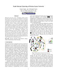
thousand matrices is a concern even on modern graphics hardware. The grass generation method of usingthe geometry shader, while lacking built-in shadows, uses far less storage.Changing Leaves with Texture ArraysTexture arrays are just what the name implies. They are arrays of textures, each with full mip-chains. For atexture2D array, the array is indexed by the z coordinate. Because the InstanceID is passed into the shader,the sample uses InstanceID%numArrayIndices to determine which texture in the array to use for renderingthat specific leaf or blade of grass.Drawing Transparent Objects with Alpha To CoverageThe number of transparent leave and blades of grass in the sample makes sorting these objects on the CPUexpensive. Alpha to coverage helps solve this problem by allowing the Instancing sample to produceconvincing results without the need to sort leaves and grass back to front. Alpha to coverage must be usedwith multisample anti-aliasing (MSAA). MSAA is a method to get edge anti-aliasing by evaluating trianglecoverage at a higher-frequency on a higher resolution z-buffer. With alpha to coverage, the MSAAmechanism can be tricked into creating psuedo order independant transparency. Alpha to coveragegenerates a MSAA coverage mask for a pixel based upon the pixel shader output alpha. That result getsAND'ed with the coverage mask for the triangle. This process is similar to screen-door transparency, but atthe MSAA level.Alpha to coverage is not designed for true order independent transparency like windows, but works greatfor cases where alpha is being used to represent coverage, like in a mipmapped leaf texture.3.4 Shadow Volume Sample3.4.1 How the Sample WorksA shadow volume of an object is the region in the scene that is covered by the shadow of the object causedby a particular light source. When rendering the scene, all geometry that lies within the shadow volumeshould not be lit by the particular light source. A closed shadow volume consists of three parts: a front cap,a back cap, and the side. The front and back caps can be created from the shadow-casting geometry: thefront cap from light-facing faces and the back cap from faces facing away from light. In addition, the backcap is formed by translating the front facing faces a large distance away from the light, to make the shadowvolume long enough to cover enough geometry in the scene. The side is usually created by firstdetermining the silhouette edges of the shadow-casting geometry then generating faces that represent thesilhouette edges extruded for a large distance away from the light direction. Figure 20 shows different partsof a shadow volume.SIGGRAPH 2006 2 – 38 Course 3, GPU Shading and Rendering
Figure 20: Creation of a shadow volume.The front cap (blue) and back cap (red) are created from the occluder's geometry. The back cap is translatedto prolong the shadow volume, and the side faces (purple) are generated to enclose the shadow volume.This sample demonstrates a specific implementation of shadow volumes. Many traditional shadow volumeapproaches determine the silhouette and generate the shadow volume geometry on the CPU. This sampledetermines the silhouette in the geometry shader and uses the fact that the geometry shader can send avariable amount of data to the rasterizer to create new shadow volume geometry on the fly. The underlyingidea is that for triangles that face the light, we can use them as-is for the front cap of the shadow volume.The back cap is generated from the front facing triangles translated a large distance along the light directionat each vertex, then they can be used as the back cap. However, a problem occurs at silhouette edges whereone triangle faces the light and its neighbor faces away from the light. In this situation, the geometry shaderextrudes two new triangles to create a quad to match up between the front cap of the shadow volume andthe back cap.In order for the geometry shader to find silhouette edges it must know which faces are adjacent to eachother. Fortunately, the geometry shader has support for a new type of input primitive, triangleadj.Triangleadj assumes that every other vertex is an adjacent vertex. The index buffer of the geometry must bemodified to reflect the adjacency information of the mesh. TheCDXUTMesh<strong>10</strong>::ConvertToAdjacencyIndices handles this by creating an index buffer in which everyother value is the index of the adjacent vertex of the triangle that shares an edge with the current triangle.The index buffer will double in size due to the extra information being stored. The figure belowdemonstrates the ordering of the adjacency information.SIGGRAPH 2006 2 – 39 Course 3, GPU Shading and Rendering
The Geometry shader that generates the shadow volume is structured as a main shader that processes thetriangles and a helper subroutine that performs the side extrusions along silhouette edges:void DetectAndProcessSilhouette(float3 N,// Un-normalized trianglenormalGSShadowIn v1, // Shared vertexGSShadowIn v2, // Shared vertexGSShadowIn vAdj, // Adjacent triangle vertexinout TriangleStream ShadowTriangleStream) {float3 NAdj = cross(v2.pos - vAdj.pos, v1.pos - vAdj.pos);// we should be not facing the lightfloat fDot = dot(N, NAdj);if (fDot < 0.0) {float3 outpos[4];float3 extrude1 = normalize(v1.pos - g_vLightPos);float3 extrude2 = normalize(v2.pos - g_vLightPos);outpos[0] = v1.pos + g_fExtrudeBias*extrude1;outpos[1] = v1.pos + g_fExtrudeAmt*extrude1;outpos[2] = v2.pos + g_fExtrudeBias*extrude2;outpos[3] = v2.pos + g_fExtrudeAmt*extrude2;}}// Extrude silhouette to create two new trianglesPSShadowIn Out;for(int v=0; v
}}DetectAndProcessSilhouette(lightDir, In[2], In[4], In[3], ShadowTriangleStream);DetectAndProcessSilhouette(lightDir, In[4], In[0], In[5], ShadowTriangleStream);//near capPSShadowIn Out;for(int v=0; v=0; v-=2) {float3 extrude = normalize(In[v].pos - g_vLightPos);float3 pos = In[v].pos + g_fExtrudeAmt*extrude;Out.pos = mul(float4(pos,1), g_mViewProj);ShadowTriangleStream.Append(Out);}ShadowTriangleStream.RestartStrip();3.4.2 Rendering ShadowsAt the top level, the rendering steps look like the following:• If ambient lighting is enabled, render the entire scene with ambient only.• For each light in the scene, do these:o Disable depth-buffer and frame-buffer writing.o Prepare the stencil buffer render states for rendering the shadow volume.o Render the shadow volume mesh with a vertex extruding shader. This sets up the stencilbuffer according to whether or not the pixels are in the shadow volume.o Prepare the stencil buffer render states for lighting.o Prepare the additive blending mode.o Render the scene for lighting with only the light being processed.The lights in the scene must be processed separately because different light positions require differentshadow volumes, and thus different stencil bits get updated. Here is how the code processes each light inthe scene in details. First, it renders the shadow volume mesh without writing to the depth buffer and framebuffer. These buffers need to be disabled because the purpose of rendering the shadow volume is merelysetting the stencil bits for pixels covered by the shadow, and the shadow volume mesh itself should not bevisible in the scene. The shadow mesh is rendered using the depth-fail stencil shadow technique and avertex extruding shader. In the shader, the vertex's normal is examined. If the normal points toward thelight, the vertex is left where it is. However, if the normal points away from the light, the vertex is extrudedto infinity. This is done by making the vertex's world coordinates the same as the light-to-vertex vectorwith a W value of 0. The effect of this operation is that all faces facing away from the light get projected toinfinity along the light direction. Since faces are connected by quads, when one face gets projected and itsneighbor does not, the quad between them is no longer degenerate. It is stretched to become the side of theshadow volume. Figure 23 shows this.SIGGRAPH 2006 2 – 41 Course 3, GPU Shading and Rendering
Figure 21: The faces of the shadow volume that face away from light (left, shown in red) have theirvertices extruded by the vertex shader to create a volume that encloses area covered by shadows(right).When rendering the shadow mesh with the depth-fail technique, the code first renders all back-facingtriangles of the shadow mesh. If a pixel's depth value fails the depth comparison (usually this means thepixel's depth is greater than the value in the depth buffer), the stencil value is incremented for that pixel.Next, the code renders all front-facing triangles, and if a pixel's depth fails the depth comparison, the stencilvalue for the pixel is decremented. When the entire shadow volume mesh has been rendered in this fashion,the pixels in the scene that are covered by the shadow volume have a non-zero stencil value while all otherpixels have a zero stencil. Lighting for the light being processed can then be done by rendering the entirescene and writing out pixels only if their stencil values are zero.Figure 22: The depth-fail technique.Figure 22 illustrates the depth-fail technique. The orange block represents the shadow receiver geometry.Regions A, B, C, D and E are five areas in the frame buffer where the shadow volume is rendered. Thenumbers indicate the stencil value changes as the front and back faces of the shadow volume are rendered.In region A and E, both the front and back faces of the shadow volume fail the depth test, and thereforeboth cause the stencil value to change. For region A, the orange shadow receiver is causing the depth test tofail, and for region E, the cube's geometry is failing the test. The net result is that stencil values in thisSIGGRAPH 2006 2 – 42 Course 3, GPU Shading and Rendering
egion stay at 0 after all faces are rendered. In region B and D, the front faces pass the depth test while theback faces fail, so the stencil values are not changed with the front faces, and the net stencil changes are 1.In region C, both the front and back faces pass the depth test, and so neither causes the stencil values tochange, and the stencil values stay at 0 in this region. When the shadow volume is completely rendered,only the stencil values in regions B and D are non-zero, which correctly indicates that regions B and D arethe only shadowed areas for this particular light.3.4.3 Performance ConsiderationsThe current sample performs normal rendering and shadow rendering using the same mesh. Because themesh class tracks only one index buffer at a time, adjacency information is sent to the shader even when itis not needed for shadow calculations. The shader must do extra work to remove this adjacency informationin the geometry shader. To improve performance the application could keep two index buffers for eachmesh. One would be the standard index buffer and would be used for non-shadow rendering. The secondwould contain adjacency information and only be used when extruding shadow volumes.Finally, there is another area that could call for some performance optimization. As shown earlier, therendering algorithm with shadow volumes requires that the scene be rendered in multiple passes (one plusthe number of lights in the scene, to be precise). Every time the scene is rendered, the same vertices get sentto the device and processed by the vertex shaders. This can be avoided if the application employs deferredlighting with multiple rendertargets. With this technique, the application renders the scene once and outputsa color map, a normal map, and a position map. Then, in subsequent passes, it can retrieve the values inthese maps in the pixel shader and apply lighting based on the color, normal and position data it reads. Thebenefit of doing this is tremendous. Each vertex in the scene only has to be processed once (during the firstpass), and each pixel is processed exactly once in subsequent passes, thus ensuring that no overdrawhappens in these passes.3.4.4 Shadow Volume ArtifactsIt is worth noting that a shadow volume is not a flawless shadow technique. Aside from the high fill-raterequirement and silhouette determination, the image rendered by the technique can sometimes containartifacts near the silhouette edges, as shown in Figure 23. The prime source of this artifact lies in the factthat when a geometry is rendered to cast shadow onto itself, its faces are usually entirely in shadow orentirely lit, depending on whether the face's normal points toward the light. Lighting computation, however,uses vertex normals instead of face normals. Therefore, for a face that is near-parallel to the light direction,it will either be all lit or all shadowed, when in truth, only part of it might really be in shadow. This is aninherent flaw of stencil shadow volume technique, and should be a consideration when implementingshadow support. The artifact can be reduced by increasing mesh details, at the cost of higher rendering timefor the mesh. The closer to the face normal that the vertex normals get, the less apparent the artifact will be.If the application cannot reduce the artifact down to an acceptable level, it should also consider using othertypes of shadow technique, such as shadow mapping or pre-computed radiance transfer.SIGGRAPH 2006 2 – 43 Course 3, GPU Shading and Rendering
Figure 23: Shadow volume artifact near the silhouette edges.Figure 24: Displaying the shadow volume reveals that the jagged edge is caused by faces that aretreated as being entirely in shadow when they are actually only partially shadowed.3.5 DisplacementMapping<strong>10</strong> SampleThis sample implements displacement mapping by ray tracing through geometry extruded from a basemesh. The sample uses <strong>Direct3D</strong> <strong>10</strong> and the geometry shader to extrude prisms which are then decomposedinto three tetrahedra for each triangle in the mesh. The pixel shader ray traces through the tetrahedra tointersect the displacement map. The diffuse color and normal values are then calculated for this point andused to set the final color of the pixel on screen. This sample is an adaptation of a paper from MicrosoftSIGGRAPH 2006 2 – 44 Course 3, GPU Shading and Rendering
Research Asia ( Wang, Xi, Xin Tong, Stephen Lin, Shimin Hu, Baining Guo, and Heung-Yeung Shum.2004. Generalized Displacement Maps. In Eurographics Symposium on Rendering 2004, pp. 227-234. )3.5.1 Sample OverviewThere have been many approaches to displacement mapping in recent history. Many rely on tessellating thegeometry to a high level of detail and then displacing this geometry based upon a height value stored in aheight map. DisplacementMapping<strong>10</strong> uses a different approach. Instead of producing detail by displacinghighly tessellated geometry, the sample creates three tetrahedra for every input triangle and uses a per-pixelray tracing approach to evaluate the geometry.3.5.2 Extruding GeometryFor every triangle on the mesh, a triangular prism is extruded. The prism is constructed by extruding thevertices of the triangle along the directions of their normals by an amount specified to be the maximumdisplacement. The XY texture coordinates at the top of the prism remain the same as the bottom; however,the Z coordinate becomes 1 to represent the maximum displacement. A naive approach would be to raytrace through this extruded prism by finding the texture coordinates where the eye ray enters and exits theprism. By taking an evenly spaced sampling of a height map texture between the entry and exit points, onecould easily determine where the ray intersects the height map.Unfortunately, there are two problems with this approach.Problem 1: Because of varying curvature in the mesh, the four points that make up each side of the prismare not guaranteed to be coplanar. When extruding the prism, each side will be split into two triangles. Anyneighboring face will also share this edge as an edge of its extruded prism. If the neighboring triangle doesnot create the sides of its prism in a way that correlates to how the current triangle creates the same edge,cracks may appear in the final rendering.SIGGRAPH 2006 2 – 45 Course 3, GPU Shading and Rendering
Problem 2: It's very hard to calculating the exit texture coordinate for an eye ray traveling through atriangular prism. The entry point, on the other hand is easy. Because of depth-buffering, the nearest triangleto the eye will always be drawn. The graphics hardware will automatically interpolate the entry texturecoordinate across the draw faces. The rear exit point is a different story. One could do ray-planeintersections to get the distance to the rear of the prism. This is a good start, but still doesn't give us thetexture coordinates. Calculating barycentrics for a triangle are costly in the shader. One could pass down anun-normalized tangent basis frame (TBN matrix) and transform the view vector into this frame, add it tothe input texture coordinate, and achieve the exit texture coordinate. Unfortunately, this breaks down whenthe mesh deforms since under high deformation, the un-normalized tangent frame is non-constant acrossthe prism.3.5.3 Using TetrahedraThe two problems above can be solve by decomposing the the prism into three tetrahedra and by using theVertexID generated by the input assembler to order the vertices when creating the tetrahedra.The distance to the rear of a tetrahedron is computed by intersecting the eye ray with the planes of thetetrahedron facing away from the eye and choosing the smallest distance. Now, the only problem left is todetermine the texture coordinates at the exit point.A nice property of a tetrahedron is that by using the texture coordinates of the 4 points, a constant texturegradient can be found across the tetrahedron. By using this gradient, the entry texture coordinate (computedeasily during rasterization), and the distance to the rear of the tetrahedron, the shader can compute the exittexture coordinates.SIGGRAPH 2006 2 – 46 Course 3, GPU Shading and Rendering
The Geometry shader used to create the tetrahedra is structured as a main shader and several helpersubroutines used to create the individual tetrahedra:struct VSDisplaceOut {float4 Pos : POS; //Positionfloat3 vPos : POSVIEW; //view posfloat3 Norm : NORMAL; //Normalfloat3 Tex : TEXCOORD0; //Texture coordinatefloat3 Tangent : TANGENT; //Normalized Tangent vectorfloat3 BiTangent : BITANGENT; //Normalized BiTangent vectoruint VertID : VertID; //verTex ID, used for consistent tetrahedrongeneration};struct PSDisplaceIn {float4 Pos : SV_Position;float4 planeDist : TEXCOORD0;float3 Norm : TEXCOORD1;};float3 vPos : TEXCOORD2;float3 TanT : TEXCOORD3; // Normalized Texture space Tangent vectorfloat3 BiTanT : TEXCOORD4; // Normalized Texture space BiTangent vectorfloat3 Tex : TEXCOORD5; // Texture Coordinate of the first vertfloat3 Gx : TEXCOORD6; // Gradient of the tetrahedron for X texcoordfloat3 Gy : TEXCOORD7; // Gradient of the tetrahedron for Y texcoordfloat3 Gz : TEXCOORD8; // Gradient of the tetrahedron for Z texcoordfloat3 pos0 : TEXCOORD9;float RayDistToPlane(float3 vPoint, float3 vDir, float3 A, float3 planeNorm) {float Nom = dot(planeNorm, float3(A - vPoint));float DeNom = dot(planeNorm, vDir);return Nom/DeNom;}void CalcGradients(inout PSDisplaceIn V0, inout PSDisplaceIn V1, inout PSDisplaceIn V2,inout PSDisplaceIn V3, float3 N0, float3 N1, float3 N2, float3 N3) {float dotN0 = dot(N0, V0.vPos - V3.vPos);float dotN1 = dot(N1, V1.vPos - V2.vPos);float dotN2 = dot(N2, V2.vPos - V1.vPos);float dotN3 = dot(N3, V3.vPos - V0.vPos);float3 Gx = (V0.Tex.x / dotN0 )*N0;Gx += (V1.Tex.x / dotN1)*N1;Gx += (V2.Tex.x / dotN2)*N2;Gx += (V3.Tex.x / dotN3)*N3;float3 Gy = (V0.Tex.y / dotN0 )*N0;Gy += (V1.Tex.y / dotN1)*N1;Gy += (V2.Tex.y / dotN2)*N2;Gy += (V3.Tex.y / dotN3)*N3;float3 Gz = (V0.Tex.z / dotN0 )*N0;Gz += (V1.Tex.z / dotN1)*N1;Gz += (V2.Tex.z / dotN2)*N2;Gz += (V3.Tex.z / dotN3)*N3;}V0.Tex = V0.Tex;V0.pos0 = V0.vPos;V0.Gx = Gx;V0.Gy = Gy;V0.Gz = Gz;V1.Tex = V0.Tex;V1.pos0 = V0.vPos;V1.Gx = Gx;V1.Gy = Gy;V1.Gz = Gz;V2.Tex = V0.Tex;V2.pos0 = V0.vPos;V2.Gx = Gx;V2.Gy = Gy;V2.Gz = Gz;V3.Tex = V0.Tex;V3.pos0 = V0.vPos;V3.Gx = Gx;V3.Gy = Gy;V3.Gz = Gz;void GSCreateTetra(in VSDisplaceOut A, in VSDisplaceOut B, in VSDisplaceOut C, inVSDisplaceOut D, inout TriangleStream DisplaceStream) {float3 AView = normalize(A.vPos - g_vEyePt);float3 BView = normalize(B.vPos - g_vEyePt);float3 CView = normalize(C.vPos - g_vEyePt);float3 DView = normalize(D.vPos - g_vEyePt);PSDisplaceIn Aout; PSDisplaceIn Bout; PSDisplaceIn Cout; PSDisplaceIn Dout;SIGGRAPH 2006 2 – 47 Course 3, GPU Shading and Rendering
Aout.Pos = A.Pos;Aout.vPos = A.vPos;Aout.Norm = A.Norm;Aout.Tex = A.Tex;Aout.TanT = A.Tangent;Aout.BiTanT =A.BiTangent ;Bout.Pos = B.Pos;Bout.vPos = B.vPos;Bout.Norm = B.Norm;Bout.Tex = B.Tex;Bout.TanT = B.Tangent;Bout.BiTanT =B.BiTangent;float3 AB = C.vPos-B.vPos;float3 AC = D.vPos-B.vPos;float3 planeNormA = normalize(cross(AC, AB));AB = D.vPos-A.vPos;AC = C.vPos-A.vPos;float3 planeNormB = normalize(cross(AC, AB));AB = B.vPos-A.vPos;AC = D.vPos-A.vPos;float3 planeNormC = normalize(cross(AC, AB));AB = C.vPos-A.vPos;AC = B.vPos-A.vPos;float3 planeNormD = normalize(cross(AC, AB));Cout.Pos = C.Pos;Cout.vPos = C.vPos;Cout.Norm = C.Norm;Cout.Tex = C.Tex;Cout.TanT = C.Tangent;Cout.BiTanT =C.BiTangent;Aout.planeDist.x = Aout.planeDist.y = Aout.planeDist.z = 0.0f;Aout.planeDist.w = RayDistToPlane(A.vPos, AView, B.vPos, planeNormA);Bout.planeDist.x = Bout.planeDist.z = Bout.planeDist.w = 0.0f;Bout.planeDist.x = Bout.planeDist.z = Bout.planeDist.w = 0.0f;Bout.planeDist.y = RayDistToPlane(B.vPos, BView, A.vPos, planeNormB);Cout.planeDist.x = Cout.planeDist.y = Cout.planeDist.w = 0.0f;Cout.planeDist.z = RayDistToPlane(C.vPos, CView, A.vPos, planeNormC);Dout.planeDist.y = Dout.planeDist.z = Dout.planeDist.w = 0.0f;Dout.planeDist.x = RayDistToPlane(D.vPos, DView, A.vPos, planeNormD);CalcGradients(Aout, Bout, Cout, Dout, planeNormA, planeNormB, planeNorm C,planeNormD);Dout.Pos = D.Pos;Dout.vPos = D.vPos;Dout.Norm = D.Norm;Dout.Tex = D.Tex;Dout.TanT = D.Tangent;Dout.BiTanT =D.BiTangent;}DisplaceStream.Append(Cout);DisplaceStream.Append(Bout);DisplaceStream.Append(Aout);DisplaceStream.Append(Dout);DisplaceStream.Append(Cout);DisplaceStream.Append(Bout);DisplaceStream.RestartStrip();void SWAP(inout VSDisplaceOut A, inout VSDisplaceOut B){VSDisplaceOut Temp = A;A = B;B = Temp;}[maxvertexcount(18)]void GSDisplaceMain(triangle VSDisplaceOut In[3], inout TriangleStreamDisplaceStream) {//Don't extrude anything that's facing too far away from us//Just saves geometry generationfloat3 AB = In[1].Pos - In[0].Pos;float3 AC = In[2].Pos - In[0].Pos;float3 triNorm = normalize(cross(AB, AC));float3 view = normalize(In[0].Pos - g_vEyePt);if (dot(triNorm, view) < 0.5) {//Extrude along the NormalsVSDisplaceOut v[6];for(int i=0; i
v[i].Pos = mul(PosNew, g_mViewProj);v[i+3].Pos = mul(PosExt, g_mViewProj);v[i].Tex = float3(In[i].Tex.xy,0);v[i+3].Tex = float3(In[i].Tex.xy,1);v[i].Norm = In[i].Norm;v[i].Norm = In[i].Norm;v[i+3].Norm = In[i].Norm;v[i].Tangent = In[i].Tangent;v[i+3].Tangent = In[i].Tangent;}v[i].BiTangent = In[i].BiTangent;v[i+3].BiTangent = In[i].BiTangent;// Make sure that our prism hasn't "flipped" on itself after the extrusionAB = v[4].vPos - v[3].vPos;AC = v[5].vPos - v[3].vPos;float3 topNorm = cross(AB, AC);float lenTop = length( topNorm );if (dot( topNorm, triNorm ) < 0 || lenTop < 0.005) {for (int i=0; i
Once the intersection point is found, all that is left is to determine the color and normal at the point ofintersection. Again, if no intersection point is found, the pixel is simply discarded. The diffuse color at theintersection point can be found by sampling the diffuse texture at the XY coordinates of the ray where theray intersected the displacement map. While the displacement map provides enough information todetermine the normal at the point of intersection (using finite differencing), this sample encodes a normalmap as the rgb components of the displacement texture (displacement is stored in alpha). Thus, the lastsample along the entry/exit ray contains the normal for the point of intersection.#define MAX_DIST <strong>10</strong>00000000.0f#define MAX_STEPS 16.0float4 PSDisplaceMain(PSDisplaceIn input) : SV_Target {float4 modDist = float4(0,0,0,0);modDist.x = input.planeDist.x > 0 ? input.planeDist.x : MAX_DIST;modDist.y = input.planeDist.y > 0 ? input.planeDist.y : MAX_DIST;modDist.z = input.planeDist.z > 0 ? input.planeDist.z : MAX_DIST;modDist.w = input.planeDist.w > 0 ? input.planeDist.w : MAX_DIST;// find distance to the rear of the tetrahedronfloat fDist = min(modDist.x, modDist.y);fDist = min(fDist, modDist.z);fDist = min(fDist, modDist.w);// find the texture coords of the entrance pointfloat3 texEnter;texEnter.x = dot(input.Gx,input.vPos-input.pos0) + input.Tex.x;texEnter.y = dot(input.Gy,input.vPos-input.pos0) + input.Tex.y;texEnter.z = dot(input.Gz,input.vPos-input.pos0) + input.Tex.z;// find the exit positionfloat3 viewExitDir = normalize( input.vPos - g_vEyePt )*fDist;float3 viewExit = input.vPos + viewExitDir;// find the texture coords of the entrance pointfloat3 texExit;texExit.x = dot(input.Gx,viewExit-input.pos0) + input.Tex.x;texExit.y = dot(input.Gy,viewExit-input.pos0) + input.Tex.y;texExit.z = dot(input.Gz,viewExit-input.pos0) + input.Tex.z;// March along the Texture space view ray until we either hit something// or we exit the tetrahedral prismfloat3 tanGrad = texExit - texEnter;tanGrad /= (MAX_STEPS-1.0);float3 TexCoord;float4 Norm_height;bool bFound = false;for (float i=0; i
Norm_height = g_txNormal.Sample(g_samPoint, TexCoord.xy);float height = Norm_height.a;if (TexCoord.z < height) {bFound = true;}}}if (!bFound)discard;// Move the light orientation into Texture spacefloat3 lightDir = normalize(g_vLightPos - input.vPos);float3 TexLight;float3 nBiTanT = input.BiTanT;float3 TexLight;float3 nBiTanT = input.BiTanT;float3 nTanT = input.TanT;float3 nNormT = input.Norm;TexLight.x = dot(lightDir, nBiTanT);TexLight.y = dot(lightDir, nTanT);TexLight.z = dot(lightDir, nNormT);// unbias the Normal mapNorm_height.xyz *= 2.0;Norm_height.xyz -= float3(1,1,1);// dot with Texture space light vectorfloat light = saturate(dot(TexLight, Norm_height.xyz));// Get the Diffuse and Specular Texturesfloat4 diffuse = g_txDiffuse.Sample(g_samLinear, TexCoord.xy);float specular = diffuse.a;// Move the viewDir into Texture spacefloat3 viewDir = normalize(-viewExitDir);float3 tanView;tanView.x = dot(viewDir, nBiTanT);tanView.y = dot(viewDir, nTanT);tanView.z = dot(viewDir, nNormT);// Calculate specular powerfloat3 halfAngle = normalize(tanView + TexLight);float4 spec = saturate(pow(dot(halfAngle, Norm_height.xyz), 64));}// Return combined lightingreturn light*diffuse*kDiffuse + spec*kSpecular*specular;3.5.5 ProblemsOne problem with this technique is also a problem with most displacement mapping techniques. In areas ofhigh concave curvature, the extruded prism can actually fold in on itself and flip. This causes the tetrahedraand resulting ray trace to be incorrect. The solution that the sample employs is to detect these cases andreduce the amount of displacement for the offending triangle.Another problem with this technique is sampling artifacts. If the number of steps per ray is too small, somehigh-frequency details can be missed. For very low sampling rates, this can cause details to pop in and outas the camera or object moves. Although geometry based displacement mapping also has frequency issues,the connectivity between the triangles ensure that there is always a smooth transition between differentheight values. Furthemore, geometry based methods are not dependent on the orientation of the view ray,so no popping of detail occurs when the object or camera moves.SIGGRAPH 2006 2 – 51 Course 3, GPU Shading and Rendering
3.5.6 Comparison with Other TechniquesIn this section, we compare traditional methods of achieving higher detail with the method this sample uses.The base mesh is 1480 polygons. For normal-mapping, the polygon count stays at 1480. For traditionaldisplacement mapping, the mesh is uniformly tessellated to a high number of polygons and then thevertices are displaced according to the height of the displacement map. For ray-traced displacement (thissample), the mesh is converted into 3 tetrahedra (4 triangles each) in the geometry shader, such that 17760triangles are actually passed to the pixel shader.Notice the lack of self occlusion or definition on the silhouette of the object.At 23680 triangles, the mesh still lacks some details. Notice the precision issues around the eyes.SIGGRAPH 2006 2 – 52 Course 3, GPU Shading and Rendering
This is a screenshot from the DisplacementMapping<strong>10</strong> sample. It uses the ray traced displacement methoddescribed above. The eye ray is traced through the geometry shader created tetrahedra and intersected withthe displacement map. This is from the base mesh of 1480 triangles that is expanded to 17760 triangles inthe GS. Notice the level of detail compared to the traditional method using 23680 triangles.This mesh was rendered using the traditional method of displacement by tessellating the mesh to 378880triangles. Compare this to the image above rendered with 1480 (17760 triangles after the GS).3.6 SparseMorphTargets SampleThis sample implements mesh animation using morph targets.SIGGRAPH 2006 2 – 53 Course 3, GPU Shading and Rendering
3.6.1 Morph TargetsThe SparseMorphTargets sample demonstrates facial animation by combining multiple morph targets ontop of a base mesh to create different facial expressions.Morph targets are different poses of the same mesh. Each of the minor variations below is a deformation ofthe base mesh located in the upper left. By combining different poses together at different intensities, thesample can effectively create many different facial poses.3.6.2 How the Sample WorksPreprocessingIn a preprocessing step, the vertex data for the base pose is stored into three 2D textures. These texturesstore position, normal, and tangent information respectively.SIGGRAPH 2006 2 – 54 Course 3, GPU Shading and Rendering
This base texture is stored into the .mt file along with index buffer data and vertex buffer data that containsonly texture coordinates. Then, for each additional morph target, the mesh is converted to three 2D textures.The base mesh textures are subtracted from the three morph target textures. The smallest subrect that canfully contain all of the differences between the two textures is then stored into the .mt file. By only storingthe smallest texture subrect that can hold all of the differences between the two meshes, the sample cutsdown on the storage requirements for the morph targets.Applying Morph Targets at RuntimeMorph targets are handled in the MorphTarget.cpp and MorphTarget.h files. These contain classes that helpwith the application of the morph targets. To apply the different morph targets to the mesh, the sample setsup a texture2Darray render target with three array indices. The first holds position data, while the secondand third hold normal and tangent information respectively.The first part of the process involves filling the render targets with the position, normal, and tangentinformation from the base pose. Then for any morph targets that need to be added, the following occurs:• The alpha blending mode is set to additive blending• The viewport is set to the exact size of the pos, norm, and tangent render targets• A quad covering only the pixels in the render target that will change for the given morph target isdrawn• This quad is drawn with the morph target position, normal, and tangent texture bound as atextured2darray• A special Geometry Shader replicates the quad three times and sends one to each render target• The Pixel Shader sets the output alpha to the blend amount. The blend amount is the amount ofinfluence this morph target should have in the final image.Effectively, the above uses the alpha blending hardware of the GPU to add up a series of sparse morphtargets to a base mesh. The position, normal, and tangent render targets now contain the vertex data of thefinal deformed mesh. These are bound as inputs to the technique that renders the final morphed meshonscreen.SIGGRAPH 2006 2 – 55 Course 3, GPU Shading and Rendering
RenderingThe input vertex stream contains a vertex reference that tells the VSRefScenemain shader which texel inthe position, normal, and tangent maps contains our vertex data. In the shader, the uiVertexRef is convertedto a 2D texture coordinate. The position, normal, and tangent data is then loaded from textures andtransformed as they would be as if they had been passed in via the vertex stream.struct VSSceneRefIn {uint uiVertexReffloat2 texfloat4 redblockfloat4 greenblockfloat4 blueblockfloat4 rgrestfloat2 brest};struct GSRefMeshIn {float4 posfloat2 texfloat3 wTanfloat3 wNormfloat3 posOrigfloat4 redblockfloat4 greenblockfloat4 blueblockfloat4 rgrestfloat2 brest};: REFERENCE;: TEXTURE;: COEFFSET0;: COEFFSET1;: COEFFSET2;: COEFFSET3;: COEFFSET4;: SV_Position;: TEXTURE0;: TEXTURE1;: TEXTURE2;: TEXTURE3;: TEXTURE4;: TEXTURE5;: TEXTURE6;: TEXTURE7;: TEXTURE8;GSRefMeshIn VSRefScenemain(VSSceneRefIn input) {GSRefMeshIn output = (GSRefMeshIn)0.0;// Find out which texel holds our datauint iYCoord = input.uiVertexRef / g_DataTexSize;// workaround for modulus // TODO: remove?uint iXCoord = input.uiVertexRef - (input.uiVertexRef/g_DataTexSize)*g_DataTexSize;float4 dataTexcoord = float4(iXCoord, iYCoord, 0, 0);dataTexcoord += float4(0.5,0.5,0,0);dataTexcoord.x /= (float)g_DataTexSize;dataTexcoord.y /= (float)g_DataTexSize;// Find our original position (used later for the wrinkle map)float3 OrigPos = g_txVertDataOrig.SampleLevel(g_samPointClamp, dataTexcoord);dataTexcoord.y = 1.0f - dataTexcoord.y;// Find our position, normal, and tangentSIGGRAPH 2006 2 – 56 Course 3, GPU Shading and Rendering
float3 pos = g_txVertData.SampleLevel(g_samPointClamp, dataTexcoord);dataTexcoord.z = 1.0f;float3 norm = g_txVertData.SampleLevel(g_samPointClamp, dataTexcoord);dataTexcoord.z = 2.0f;float3 tangent = g_txVertData.SampleLevel(g_samPointClamp, dataTexcoord);// Output our final positions in clipspaceoutput.pos = mul(float4(pos, 1), g_mWorldViewProj);output.posOrig = mul(float4(OrigPos, 1), g_mWorldViewProj);// Normal and tangent in world spaceoutput.wNorm = normalize(mul(norm, (float3x3)g_mWorld ));output.wTan = normalize(mul(tangent, (float3x3)g_mWorld ));// Just copy ldprt coefficientsoutput.redblock = input.redblock;output.greenblock = input.greenblock;output.blueblock = input.blueblock;output.rgrest = input.rgrest;output.brest = input.brest;// Prop texture coordinatesoutput.tex = input.tex;}return output;3.6.3 Adding a Simple Wrinkle ModelTo add a bit of realism the sample uses a simple wrinkle model to modulate the influence of the normalmap in the final rendered image. When rendering the final morphed image, the Geometry Shader calculatesthe difference between the triangle areas of the base mesh and the triangle areas of the current morphedmesh. These differences are used to determine whether the triangle grew or shrank during the deformation.If it shrank, the influence of the normal map increases. If it grew, the influence of the normal mapdecreases.struct PSRefMeshIn {float4 posfloat2 texfloat3 wTanfloat3 wNormfloat wrinklefloat4 redblockfloat4 greenblockfloat4 blueblockfloat4 rgrestfloat2 brest};: SV_Position;: TEXTURE0;: TEXTURE1;: TEXTURE2;: WRINKLE;: TEXTURE3;: TEXTURE4;: TEXTURE5;: TEXTURE6;: TEXTURE7;[maxvertexcount(3)]void GSCalcWrinkles(triangle GSRefMeshIn input[3], inout TriangleStreamRefStream ) {// Find the area of our trianglefloat3 vortho = cross(input[1].pos-input[0].pos, input[2].pos-input[0].pos);float areaNow = length( vortho ) / 2.0;vortho = cross(input[1].posOrig-input[0].posOrig, input[2].posOrig-input[0].posOrig);float areaOrig = length( vortho ) / 2.0;for (int v=0; v
output.greenblock = input[v].greenblock;output.blueblock = input[v].blueblock;output.rgrest = input[v].rgrest;output.brest = input[v].brest;float w = ((areaOrig-areaNow)/ areaOrig)*1.0;if (w < 0)w *= 0.005f;output.wrinkle = saturate( 0.3 + w );}RefStream.Append(output);}RefStream.RestartStrip();3.6.4 Adding Illumination Using LDPRTLocal Deformable Precomputed Radiance Transfer is used to light the head. The PRT simulation is done onthe base mesh and the 4th order LDPRT coefficients are saves to a .ldprt file. The sample loads this file intomemory and merges it with the vertex buffer at load time. The bulk of the LDPRT lighting calculations arehandled by GetLDPRTColor. The current implementation only uses 4th order coefficients. However,uncommenting the last half of GetLDPRTColor, re-running the PRT simulation to generate 6th ordercoefficients, and changing dwOrder to 6 in UpdateLightingEnvironment may give a better lightingapproximation for less convex meshes.For a more detailed explanation of Local Deformable Precomputed Radiance Transfer, refer to the<strong>Direct3D</strong> 9 LocalDeformablePRT sample or the PRTDemo sample.SIGGRAPH 2006 2 – 58 Course 3, GPU Shading and Rendering
AcknowledgementsThis material is drawn from a number of sources including contributions from the Microsoft DirectXdevelopment, sample, and documentation teams: Mike Toelle, Sam Glassenberg, John Ketchpaw, IouriTarassov, Brian Klamik, Jeff Noyle, Relja Markovic, John Rapp, Craig Peeper, Peter-Pike Sloan, JasonSandlin, Shanon Drone, and Kris Gray.SIGGRAPH 2006 2 – 59 Course 3, GPU Shading and Rendering
SIGGRAPH 2006 2 – 60 Course 3, GPU Shading and Rendering