Plasma Etching of Polycrystalline Silicon Films Using Chlorine ...
Plasma Etching of Polycrystalline Silicon Films Using Chlorine ...
Plasma Etching of Polycrystalline Silicon Films Using Chlorine ...

You also want an ePaper? Increase the reach of your titles
YUMPU automatically turns print PDFs into web optimized ePapers that Google loves.
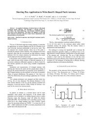
DDOxide Grown (0.07µm)Poly-Si Deposition (0.6µm)Oxide Grown (0.07µm)Substrate (400µm) Substrate (400µm) Substrate (400µm)(a)UV Light(b)(c)ResetSenseNodeMaskPhotoresist (1.0µm)Poly-Si Deposition (0.6µm)Oxide Grown (0.07µm)Poly-Si deposition (0.6µm)Oxide Grown (0.07µm)Substrate (400µm)Substrate (400µm)phout(d)(e)biasFig. 2.Fabrication <strong>of</strong> SampleFig. 1.C. Sample PreparationCircuit DesignThe circuit was processed on p-type boron doped siliconwafers. Figure 4 presents a schematic device cross-sectionand all fabrication steps are described in table I. Howeveras it was shown in the table I, it had been used humid etch,that for etch in less structures than 2µm, they can worsenthe acting <strong>of</strong> the circuit or even destroying him. A similarstructure was manufactured like this with smaller dimensionsfor test using etch plasma. The samples were formedusing n-type Si (100) wafers. <strong>Silicon</strong> oxide (SiO 2 ) <strong>of</strong> 0.07µm and 0.5 µm thickness were grown by conventionalfurnace and LPCVD (Low pressure chemical vapor deposition),respectively. Deposition <strong>of</strong> poly-Si layer <strong>of</strong> 0.6µmhickness is performed using a LPCVD. Photoresist AZ3312 with thickness <strong>of</strong> 1.4µm was then applied, followedby a photolithography using a photoaligner (Karl SussMBJ3), where the patterns (lines) were transferred for thephotorresist. Removal <strong>of</strong> the photoresist after lithographystep was done using MIF 300 [9] as shown in fig. 2.A. Processes <strong>of</strong> <strong>Etching</strong>III. RESULTS AND DISCUSSION<strong>Etching</strong> parameters such as the ratio <strong>of</strong> gas flows in themixture, RF power, pressure were optimized in a series <strong>of</strong>experiments to improve the selectivity S and anisotropyfactor A, defined in the equations [1] and [2] below:S = ER P olyER SiO2(1)A = 1 − ER LER V(2)where poly ER is etch rate <strong>of</strong> the poly-Si, SiO 2 ER isetch rate <strong>of</strong> SiO 2 , ER L is the rate <strong>of</strong> lateral etching andER V is rate <strong>of</strong> vertical etching. We used here mixtures<strong>of</strong> SF 6 to promote high etch rates and Cl 2 as a stronginhibitor <strong>of</strong> lateral etching [1]. The figure 3 demonstratesthe effects <strong>of</strong> chlorine content on the vertical etch rate <strong>of</strong>Si and anisotropy, see also [2], [9], [10].Fig. 3. Anisotropy factor and etch rate versus Cl 2 flow, Ar/SF 6 /Cl 2 ,total flow 47 sccm, SF 6 fixed flow 12 sccm,Cl 2 increases proportionalinversely to the Ar.Two recipes were used containing the mixtures (Ar/SF 6and Ar/SF 6 /Cl 2 ): (i) First, for Ar/SF 6 = 35/12 sccm, an2009 SBMO/IEEE MTT-S International Microwave & Optoelectronics Conference (IMOC 2009) 647
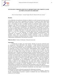
StepDescription1 RCA standard cleaning2 65keV, 1x1013cm-2 boron3 implantation for threshold voltage adjustment4 Dopant activation and wet oxidation (7370Å)5 First photolithography and oxide etch with HF Buffer: definition <strong>of</strong> source and drain regions6 65keV, 5x1015 cm-2 phosphorus implantation. N+ region formation: source, drain and diode pn-junctions7 Dopant activation and wet oxidation (5750Å)8 Second photolithography and oxide etch with HF Buffer: definition <strong>of</strong> channel and via regions9 Dry oxidation for growing a high quality gate oxide (550)10 Third photolithography and oxide etching with HF Buffer: opening vias11 Aluminum sputtering deposition ( 5000Å)12 Fourth photolithography and aluminum etch with orthophosphoric acid (H3PO4): definition <strong>of</strong> the interconnection layer13 Aluminum sputtering deposition ( 5000Å)14 AnnealingTABLE IPROCESS DESCRIPTIONRF power <strong>of</strong> 500 W, pressure <strong>of</strong> 50 mTorr and time <strong>of</strong>4 minutes, it was possible to obtain etch rate for polyup to 300nm/min, selectivity for oxide as high as ∼ 24and good quality <strong>of</strong> the surface in the interface poly/SiO 2(mean roughness ∼ 10Å); (ii) Ar/SF 6 /Cl 2 =19/12/16 sccm,an RF power <strong>of</strong> 500 W, pressure <strong>of</strong> 50 mTorr and time <strong>of</strong>12 minutes, it was possible to obtain good anisotropy andreasonable selectivity for oxide (∼ 20) and surface qualityin the interface poly/SiO 2 . The Figure 4 shows SEM imagesfor the Ar/SF 6 and Ar/SF 6 /Cl 2 mixtures, respectively,with the corresponding etch pr<strong>of</strong>iles and etch results shownbelow. Significant improvement <strong>of</strong> anisotropy can be seenin ther latter case.Bias= -133VAnisotropy = 0,46Etch rate = 300nm/minSelectivity poli/SiO 2 = 2435Ar/12SF 6 , 500W, 50mTorr, 4minBias= -128VAnisotropy = 0,9Etch rate = 51nm/minSelectivity poli/SiO 2 = 2035Ar/12SF 6 /16Cl 2 , 500W,50mTorr,12minIV. CONCLUSIONResults <strong>of</strong> reactive ion etching (RIE) <strong>of</strong> poly-Si andother Si-based materials using a capacitively coupled industrialhexode reactor for optical sensors applications,are presented. To provide higher anisotropy <strong>of</strong> etchingand selectivity <strong>of</strong> poly-Si etching, fluorine and chlorinecontaining mixtures (Ar/SF 6 and Ar/SF 6 /Cl 2 ) were used.<strong>Chlorine</strong> is known as strong inhibitor <strong>of</strong> lateral Si etching,while better selectivity (over SiO 2 and SiNx) can beachieved with fluorine. <strong>Using</strong> Ar/SF 6 = 35/12 sccm mixtures,RF power <strong>of</strong> 500 W and pressure <strong>of</strong> 50 mTorr, it waspossible to obtain high etch rate for poly-Si ( 300nm/min).<strong>Using</strong> Ar/SF 6 /Cl 2 = 35/12/16 sccm mixtures, RF power <strong>of</strong>500 W and pressure <strong>of</strong> 50 mTorr, anisotropy <strong>of</strong> etchingwas improved to 0.85-0.9, compared with 0.4-0.5 for thefluorine based mixture. Selectivities for etching <strong>of</strong> poly-Si over oxide as high as ∼ 24 and 20 were obtainedfor Ar/SF 6 and Ar/SF 6 /Cl 2 mixtures, respectively. Highquality <strong>of</strong> the surface at the interface SiO 2 /polysilicon(medium roughness ∼ 10Å) was also demonstrated. ForSiO 2 etching, high etch rate (∼ 55 nm/min) was achievedusing Ar/SF 6 = 45/7 sccm at low pressure (10 mTorr) andhigh RF power (1000 W). For photoresist etching, O 2plasma was used, at pressure <strong>of</strong> 50mTorr, power <strong>of</strong> 200W.ACKNOWLEDGMENTThe authors would like to thank CCS staff for deviceprocessing and characterization. The work is supported byFAPESP, FINEP and UFAM/CTPIMREFERENCESFig. 4. Image SEM line <strong>of</strong> poly-Si for mask before etching with linethickness <strong>of</strong> 2µm.[1] A. Makynen, T. Ruotsalainen, J. Kostamovaara, Electronic letters,33, 2 (1997).[2] S. M. Sze, VLSI Technology, McGRAWHill Internacional Editions,2nd Edition, 1983.2009 SBMO/IEEE MTT-S International Microwave & Optoelectronics Conference (IMOC 2009) 648
[3] T. Skotnicki, M.Jurczak, J. Martins, M. Paoli, B. Tormen, R. Pantel,C. Hernandez, I. Campidelli, E. Josse, G. Ricci, J. Galvier, ”Wellcontrolled,selectively under-etched Si/SiGe gates for RF and highperformance CMOS”, ST Microelectronics, 850 rue J. Monnet,38926 Crolles Cedex, France, 2000.[4] Tae Won Kim and Eray S. Aydil ”Effects <strong>of</strong> Chamber Wall Conditionson Cl Concentration and Si Etch Rate Uniformity in <strong>Plasma</strong><strong>Etching</strong> Reactors”, Department <strong>of</strong> Chemical Engineering, University<strong>of</strong> California, Santa Barbara, California 93106, USA.[5] Masaaki Satoa and Yoshinobu Arita ”Control <strong>of</strong> etching-productdependentshape and selectivity in gate polysilicon reactive ionetching”, NTT System Electronics Laboratories, 3-1, Morinosato-Wakamiya, Atsugi-shi, Kanagawa 243-01, Japan,1998.[6] S. Wolf, and R. N. Tauber, <strong>Silicon</strong> Processing for the VLSI Era,Process Technology. Lattice Press, California, 1986.[7] D. W. de Lima Monteiro, CMOS-based Integrated Wavefront Sensor,DUP Science (2002).[8] D. S. de Lara, L. O. S. Ferreira, J. W. Swart, Advances in the Processand in the Methology od Emulsion Optical Masks Construction, p.371-379, Proc. SBMICRO (2003).[9] Alcinei Moura Nunes, Corroso por <strong>Plasma</strong> de Silicio Policristalinoe Nitreto de Silcio para Tecnologias MENS e CMOS, Tese deMestrado, UNICAMP, Campinas - SP, 2005.[10] Alcinei Moura Nunes, <strong>Plasma</strong> <strong>Etching</strong> for <strong>Polycrystalline</strong> <strong>Silicon</strong><strong>Using</strong> Thinning Technology Application in Technologies MENS andCMOS, Journal Integrated Circuits and Systems; vol 2 P 74-80,2007.2009 SBMO/IEEE MTT-S International Microwave & Optoelectronics Conference (IMOC 2009) 649