

Installation instructions - DJM Suspension
Installation instructions - DJM Suspension
Installation instructions - DJM Suspension

Create successful ePaper yourself
Turn your PDF publications into a flip-book with our unique Google optimized e-Paper software.
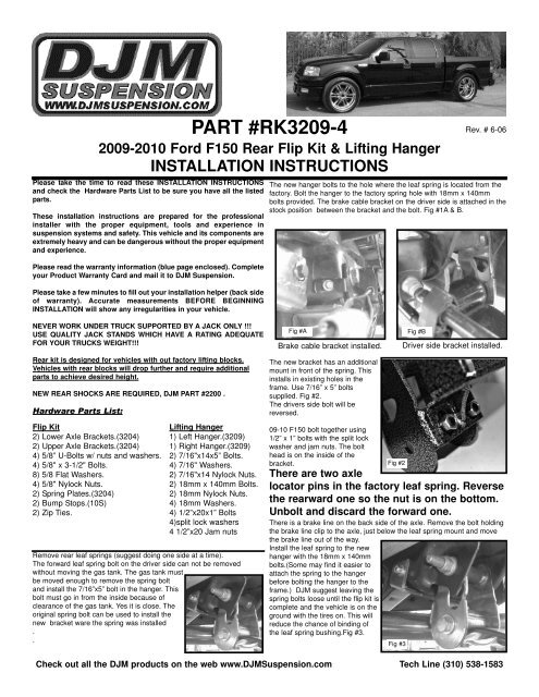
Please take the time to read these INSTALLATION INSTRUCTIONSand check the Hardware Parts List to be sure you have all the listedparts.These installation <strong>instructions</strong> are prepared for the professionalinstaller with the proper equipment, tools and experience insuspension systems and safety. This vehicle and its components areextremely heavy and can be dangerous without the proper equipmentand experience.Please read the warranty information (blue page enclosed). Completeyour Product Warranty Card and mail it to <strong>DJM</strong> <strong>Suspension</strong>.Please take a few minutes to fill out your installation helper (back sideof warranty). Accurate measurements BEFORE BEGINNINGINSTALLATION will show any irregularities in your vehicle.NEVER WORK UNDER TRUCK SUPPORTED BY A JACK ONLY !!!USE QUALITY JACK STANDS WHICH HAVE A RATING ADEQUATEFOR YOUR TRUCKS WEIGHT!!!Rear kit is designed for vehicles with out factory lifting blocks.Vehicles with rear blocks will drop further and require additionalparts to achieve desired height.NEW REAR SHOCKS ARE REQUIRED, <strong>DJM</strong> PART #2200 .Hardware Parts List:PART #RK3209-42009-2010 Ford F150 Rear Flip Kit & Lifting HangerINSTALLATION INSTRUCTIONSFlip Kit2) Lower Axle Brackets.(3204)2) Upper Axle Brackets.(3204)4) 5/8” U-Bolts w/ nuts and washers.4) 5/8" x 3-1/2" Bolts.8) 5/8 Flat Washers.4) 5/8" Nylock Nuts.2) Spring Plates.(3204)2) Bump Stops.(10S)2) Zip Ties.Lifting Hanger1) Left Hanger.(3209)1) Right Hanger.(3209)2) 7/16"x14x5” Bolts.4) 7/16" Washers.2) 7/16"x14 Nylock Nuts.2) 18mm x 140mm Bolts.2) 18mm Nylock Nuts.4) 18mm Washers.4) 1/2”x20x1” Bolts4)split lock washers4 1/2”x20 Jam nutsRemove rear leaf springs (suggest doing one side at a time).The forward leaf spring bolt on the driver side can not be removedwithout moving the gas tank. The gas tank mustbe moved enough to remove the spring boltand install the 7/16”x5” bolt in the hanger. Thisbolt must go in from the inside because ofclearance of the gas tank. Yes it is close. Theoriginal spring bolt can be used to install thenew bracket ware the spring was installed..Rev. # 6-06The new hanger bolts to the hole where the leaf spring is located from thefactory. Bolt the hanger to the factory spring hole with 18mm x 140mmbolts provided. The brake cable bracket on the driver side is attached in thestock position between the bracket and the bolt. Fig #1A & B.Fig #A Fig #BBrake cable bracket installed.The new bracket has an additionalmount in front of the spring. Thisinstalls in existing holes in theframe. Use 7/16” x 5” boltssupplied. Fig #2.The drivers side bolt will bereversed.09-10 F150 bolt together using1/2” x 1” bolts with the split lockwasher and jam nuts. The bolthead is on the inside of thebracket.Fig #2There are two axlelocator pins in the factory leaf spring. Reversethe rearward one so the nut is on the bottom.Unbolt and discard the forward one.There is a brake line on the back side of the axle. Remove the bolt holdingthe brake line clip to the axle, just below the leaf spring mount and movethe brake line out of the way.Install the leaf spring to the newhanger with the 18mm x 140mmbolts.(Some may find it easier toattach the spring to the hangerbefore bolting the hanger to theframe.) <strong>DJM</strong> suggest leaving thespring bolts loose until the flip kit iscomplete and the vehicle is on theground with the tires on. This willreduce the chance of binding ofthe leaf spring bushing.Fig #3.Check out all the <strong>DJM</strong> products on the web www.<strong>DJM</strong><strong>Suspension</strong>.com Tech Line (310) 538-1583Fig #3Driver side bracket installed.
PART #RK3204-42004-2007 F150 Rear Flip Kit & Lifting HangerINSTALLATION INSTRUCTIONS cont.Reinstall the leaf spring under the axle. Place the new axle locatorbracket on top of the spring, line up the hole in the bracket with the pin inthe spring. Lower the rear axle into the new axle supports.Place the new upper axle plates, withthe pin down in the rearward hole, ontop of the axle. Install and tighten the5/8” bolts provided with one flatwashers on top of the upper plate andone on the bottom of the axle locator.Tighten U-Bolts. Check all bolts.Install new U-bolts and spring plates (5 hole) on the bottom of the springs.Tighten u-bolts to hold axle in place, you may need to loosen them againto adjust drive line angle.Temporarily bolt on wheels and set vehicle down. Tighten shackle boltsand spring bolts.Use the zip ties to secure the brake line clipto the 5/8” bolt.Check the drive line angle. You want the drive shaft to be straight fromthe transmission back to the rear end. This can only be checked with thetires on the ground(at ride height). Adjust pinion angle as necessary.Remove factory bump stop. The new bumpstop will thread into the factory hole in theframe.Install rear wheels and torque lug nuts.Test drive and adjust pinion angle as necessary. Measure and record theheight of the rear on the installation helper.Check out all the <strong>DJM</strong> products on the web www.<strong>DJM</strong><strong>Suspension</strong>.com Tech Line (310) 538-1583


