USB-Synthesizer - SDR-Kits
USB-Synthesizer - SDR-Kits
USB-Synthesizer - SDR-Kits
- No tags were found...

You also want an ePaper? Increase the reach of your titles
YUMPU automatically turns print PDFs into web optimized ePapers that Google loves.
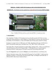
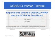
<strong>SDR</strong>-<strong>Kits</strong>.net QRP2000 <strong>USB</strong>-Controlled <strong>Synthesizer</strong> Kit Assembly v2.03c( ) Remove Power to PCB( ) Caution: observe anti-static precautions handling semiconductor( ) Plug ATTiny45 or ATTiny 85 IC holder for U1 – pin 1 should be aligned towards U3 on thetop silk( ) Connect <strong>USB</strong> <strong>Synthesizer</strong> to <strong>USB</strong> socket of a Personal Computer and measure voltagebetween U1 Pin 8. Reading should be around 4.3V DC( ) Disconnect <strong>USB</strong> cable from <strong>USB</strong> <strong>Synthesizer</strong>Final assembly of Si570 Device( ) Caution: observe antistatic precautions handling semiconductors( ) The Si570 device is soldered on the bottom of the PCB( ) Locate the Dot on the Si570 device and align with pin 1 marked on the PCB and solder.The Dot is located on the left hand side of bottom line showing the Batchnumber.Fig 4Location of S570 chip – Bottom left pin is Pin 1 aligned with dot on Si571<strong>SDR</strong>-<strong>Kits</strong>.net © 2008 & 2009 by QRP2000 Design Page 8 of 28