USB-Synthesizer - SDR-Kits
USB-Synthesizer - SDR-Kits
USB-Synthesizer - SDR-Kits
- No tags were found...

You also want an ePaper? Increase the reach of your titles
YUMPU automatically turns print PDFs into web optimized ePapers that Google loves.
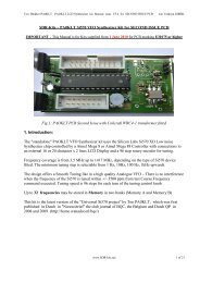
<strong>SDR</strong>-<strong>Kits</strong>.net QRP2000 <strong>USB</strong>-Controlled <strong>Synthesizer</strong> Kit Assembly v2.03c( ) Solder Outer conductor of coaxial cable to JP1 pin 4 (Ground) as shown below.Fig 6: Connection of Coaxial Cable to RXTX PCB JP1( ) On <strong>USB</strong> <strong>Synthesizer</strong> board solder inner conductor of coax cable to pin A( ) Solder outer braid of coax cable to centre pin B( ) Connect wire from +12V terminal to +12VDC terminal of RXTX PCB( ) Connect wire from <strong>USB</strong>-<strong>Synthesizer</strong> “PTT” to RXTX PCB “PTT_IN”www.<strong>SDR</strong>-kits.net+12VfromRXTXTo PTT_In onRXTX PCBA: Inner CoaxB: outer braidFig 7: Connections on <strong>USB</strong>-<strong>Synthesizer</strong> PCB to support Softrock RXTX<strong>SDR</strong>-<strong>Kits</strong>.net © 2008 & 2009 by QRP2000 Design Page 22 of 28