MODBUS-RTU Option Board for SV-iS5 Series User ... - ayper elektr?
MODBUS-RTU Option Board for SV-iS5 Series User ... - ayper elektr?
MODBUS-RTU Option Board for SV-iS5 Series User ... - ayper elektr?
- No tags were found...

You also want an ePaper? Increase the reach of your titles
YUMPU automatically turns print PDFs into web optimized ePapers that Google loves.
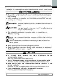
Thank you <strong>for</strong> purchase of LG Modbus-<strong>RTU</strong> <strong>Option</strong> <strong>Board</strong>!SAFETY PRECAUTIONS• Always follow safety precautions to prevent accidents and potential hazards from occurring.• Safety precautions are classified into “WARNING” and “CAUTION” in this manual.WARNINGCAUTIONIndicates a potentially hazardous situation which, if not avoided,can result in serious injury or death.Indicates a potentially hazardous situation which, if not avoided,can result in minor to moderate injury, or serious damage to theproduct.• Throughout this manual we use the following two illustrations to make you aware of safetyconsiderations:Identifies potential hazards (under certain conditions ).Read the message and follow the instructions carefully.Identifies shock hazards(under certain conditions ).Particular attention should be directed because dangerous voltage may be present.• Keep this manual at handy <strong>for</strong> quick reference.CAUTION• Do not touch the CMOS components unless the board is grounded.ESD can cause break down of CMOS components.• Do not change the communication cable with the inverter power is turned on.Otherwise, there is a danger of connecting error and damage to the board.• Make sure to precisely insert the connector of inverter and option boardOtherwise, there is a danger of connecting error and damage to the board.• Check the parameter unit when setting the parameters.Otherwise, there is a danger of connecting error and damage to the board.
1. INTRODUCTIONBy using a <strong>MODBUS</strong>-<strong>RTU</strong> <strong>Option</strong> board, <strong>SV</strong>-<strong>iS5</strong> inverter can be connected to a <strong>MODBUS</strong>-<strong>RTU</strong> network.1.1. When you use the <strong>MODBUS</strong>-<strong>RTU</strong> <strong>Option</strong> Card …Inverter can be controlled and monitored by the sequence program of the PLC or other master module. Thecard provides a terminal block <strong>for</strong> an RS-485 interface. Up to 32 drives or other Modbus slave devices maybe connected in a multi-drop fashion on the RS-485 Modbus network and may be monitored or controlled bya single PLC or PC.1.1.1 Interfacing type of <strong>RTU</strong> Reference:- Allows the drive to communicate with any other computers.- Allows connection of up to 31 drives with multi-drop link system.- Ensure noise-resistant interface.<strong>User</strong>s can use any kind of RS232-485 converters. However a converter that has built-in ‘automatic RTScontrol’ is highly recommended. The specifications of converters depend on the manufacturers. Refer to theconverter manual <strong>for</strong> detailed converter specifications.1.1.2 Be<strong>for</strong>e InstallationBe<strong>for</strong>e installation and operation, this manual should be read thoroughly. If not, it can cause personal injuryor damage other equipment.2. SPECIFICATION2.1. Per<strong>for</strong>mance specificationItemsCommunication methodTransmission <strong>for</strong>mApplicable inverterNumber of drivesTransmission distanceConverterSpecificationsRS485Bus method Multi-drop Link SystemIS5 series driveMaximum 31 drives connectableMax. 1200m (Less than 700 m recommended)RS232-485, Use PC with RS232 card embedded2.2. Hardware SpecificationsItemsSpecificationsInstallationCN2 connector on the inverter control boardPower Control B/D From inverter power supplySupply Comm. B/D From control board (insulated)1 modbus-rtu <strong>iS5</strong> manual.doc
2.3. Communication SpecificationItemsCommunication speedControl procedureCommunication systemCharacter systemStart/Stop bitError check (CRC16)Parity checkSpecifications1200 /2400/4800/9600/19200 bps SelectableAsynchronous communication systemHalf duplex systemBinary (8 bit)1 bit2 byteNone3. PRODUCT DETAIL3.1. Layout and detailNameConnectorSignalconnectionterminalCommunicationsignal connectionterminalDescriptionCN2, Connector to inverter main PCBP485 signal - highN485 signal – lowG485 GroundSShieldT1Short T1 and T2 to connect aT2termination resistorFigure 1. Layout2modbus-rtu <strong>iS5</strong> manual.doc
3.2. Status LEDCPU LEDRXD LEDTXD LEDERR LEDIndicates normal operation of the board when blinking once per second.Receiving 485 signalResponding to 485 signalOn and Off intermittentlyWrong DATA received (Normal operating)Blinking with CPU LED at the same DPRAM communication faulttimeBlinking with CPU LED in an Network Connection TimeOut opposite wayelapsed4. INSTALLATION1. Connect the option board to the inverter control board using each connector on the board (See theFigure 1).2. Double check the board is firmly installed to the board and then apply the inverter power.3. When power ON, CPU LED is blinking per second after all LEDs blink one after another.4. If “CPU LED” is not blinking, turn off the inverter power swiftly (if not, inverter and the board may getdamaged.) and check <strong>for</strong> the proper installation of the board. If the problem persists, contact LGdistributor.5. Check ModBus-<strong>RTU</strong> is displayed in .6. Set the parameters as below when the above steps are all done.Parameter code Display Setting Value< COM-01 > Opt B/D <strong>MODBUS</strong> displayed automatically< COM-02 > Opt modeSet the Command controlled viacommunication< I/O- 46 > Inv. number1~31(Verify the assigned number is not duplicated)< I/O- 47 > Baud-rate 9600 bps (Factory default)< I/O- 48 > Lost command (Note1) <strong>User</strong> setting< I/O- 49> TimeOut (Note 1) 0.1 sec (Factory default)Note 1) it is used <strong>for</strong> Emergency Stop when communication between inverter and master is not doneproperly. It is activated when communication is not done even once <strong>for</strong> the set time. It means remotecontrolling of inverter is not done. Set this value <strong>for</strong> safety7. Turn off the inverter power <strong>for</strong> the connection of the Converter when step 6 is finished.8. if the inverter is to be placed at the end of the network trunk line, install a jumper at JP1 on theModbus card to enable the termination resistor.3modbus-rtu <strong>iS5</strong> manual.doc
5. TROUBLE SHOOTINGIf communications cannot be established with the drive, there are four LEDs on the Modbus card to aid introubleshooting. The CPU LED should blink once per second to indicate that the modbus card is interfacingwith the inverter main PCB properly. The RXD LED should blink each time a properly <strong>for</strong>med Modbusmessage is received that is addressed to the inverter. The RXD LED will not blink when messages arereceived that are addressed to other inverters or devices. The TXD LED should blink each time the inverterresponds to a Modbus message. The ERR LED indicates either an invalid request was received or there is aproblem with the Modbus card itself. The ERR LED should never light. CPU LEDState Indicates Corrective measuresBlinking Card is installed properly and workingOffnormallyCard is not installed properlyVerify that the card is installedproperlyInverter is not operating normallyVerify that the inverter has power RXD and TXD LEDsState Indicates Corrective measuresBlinking Card is functioning normally and receiving andsending messagesOff Incorrect Modbus connection to the card Verify that the Low signal isconnected to terminal N and theHigh signal is connected to terminalPMaster is not pollingVerify that the master (PLC or PC) ispolling the inverter.Incorrect baud rate settingVerify that the baud rate (I/O47) isset to match the baud rate of theinverter.Incorrect byte <strong>for</strong>mat The inverter communicates using 8data bits, 1 stop bit and no paritybits. Verify that the master is set tothe same.4modbus-rtu <strong>iS5</strong> manual.doc
ERR LEDState Indicates Corrective measuresOn/off from timeto timeBlinking with CPULED at the sametimeBlinking after CPULED one afteranotherOffThe card is receiving invalid data such Normalas noise.Trouble with the Modbus cardCycle the Inverter power. If theproblem persists, contact LGNetwork communication is not done Verify that the master is specifyingduring TimeOut (I/O 49) setting. valid register addresses and validdata.The card is functioning normally andreceiving and sending messages*See COM group <strong>for</strong> Frequency/Run command setting.5modbus-rtu <strong>iS5</strong> manual.doc
2 PARAMETER CODE (HEX) Area accessible regardless of inverter models (Note 3)ParameterAddressParameter Name Unit Read/Write Data Value (Hex)0x0000 Drive model - R 4: <strong>SV</strong>-<strong>iS5</strong>0: 0.75 1:1.5 2:2.2 3: 3.74: 5.5 5: 7.5 6: 11 7: 158: 18.5 9: 22 A: 30 B:370x0001 Drive capacity - R C:45 D: 55 E: 75 F: 9010: 110 11: 132 12: 16013: 200 14:220 15:28016:375 (Unit : kW)0x0002 Drive Input Voltage - R 0: 220V 1: 440V0x0003 S/W Version - R0100: Ver. 1.00,0101: Ver 1.010x0005 Frequency Reference 0.01Hz R/W0x0006 Run Command - R/WBit 0: StopBit 1: Forward RunBit 2: Reverse RunBit 3: Fault ResetBit 4: Emergency Stop0x0007 Acceleration Time 0.1 sec R/W0x0008 Deceleration Time 0.1 sec R/W0x0009 Output Current 0.1 A R0x000A Output Frequency 0.01 Hz R0x000B Output Voltage 0.1 V R0x000C DC Link Voltage 0.1 V R0x000D Output Power 0.1 kW R0x000E Sequence Monitor - RBIT 0 : StopBIT 1 : Forward RunBIT 2 : Reverse RunBIT 3 : Fault (Trip)BIT 4 : AcceleratingBIT 5 : DeceleratingBIT 6 : Output FrequencyArrival6modbus-rtu <strong>iS5</strong> manual.doc
Address NO. Description Default Maximum Minimum Unit5105 DRV#05 Step freq - 1 1000 MaxFreq startFreq 0.01Hz5106 DRV#06 Step freq - 2 2000 MaxFreq startFreq 0.01Hz5107 DRV#07 Step freq - 3 3000 MaxFreq startFreq 0.01Hz5108 DRV#08 Current - - - 0.1A5109 DRV#09 Speed - - - 1rpm510A DRV#10 DC Link Voltage - - V< FU1 Group >Address NO. Description Default Maximum Minimum Unit5203 FU1 #03 Run prohibit 0 2 05205 FU1 #05 Acc. pattern 0 4 05206 FU1 #06 Dec. pattern 0 4 05207 FU1 #07 Stop mode 0 2 05208 FU1 #08 DcBr freq. 500 6000 startFreq 0.01Hz5209 FU1 #09 DcBlk time 10 6000 0 0.01sec520A FU1 #10 DcBr value 50 200 0 %520B FU1 #11 DcBr time 10 600 0 0.1sec520C FU1 #12 DcSt value 50 200 0 %520D FU1 #13 DcSt time 0 600 0 0.1sec5214 FU1 #20 Max freq. 6000 40000 4000 0.01Hz5215 FU1 #21 Base freq. 6000 maxFreq 3000 0.01Hz5216 FU1 #22 Start freq. 50 6000 1 0.01Hz5217 FU1 #23 Freq limit 0 1 05218 FU1 #24 F-limit Lo. 50 highFreq startFreq 0.01Hz5219 FU1 #25 F-limit Hi. 6000 maxFreq lowFreq 0.01Hz521A FU1 #26 Torque boost 0 1 0521B FU1 #27 Fwd boost 20 150 0 0.1%521C FU1 #28 Rev boost 20 150 0 0.1%521D FU1 #29 V/F pattern 0 2 0521E FU1 #30 <strong>User</strong> freq. 1 1500 maxFreq 0 0.01Hz521F FU1 #31 <strong>User</strong> volt. 1 25 100 0 %5220 FU1 #32 <strong>User</strong> freq. 2 3000 maxFreq 0 0.01Hz5221 FU1 #33 <strong>User</strong> volt. 2 50 100 0 %5222 FU1 #34 <strong>User</strong> freq. 3 4500 maxFreq 0 0.01Hz5223 FU1 #35 <strong>User</strong> volt. 3 75 100 0 %5224 FU1 #36 <strong>User</strong> freq. 4 6000 maxFreq 0 0.01Hz5225 FU1 #37 <strong>User</strong> volt. 4 100 100 0 %5226 FU1 #38 Volt control 1000 1100 400 0.1%8modbus-rtu <strong>iS5</strong> manual.doc
Address NO. Description Default Maximum Minimum Unit5227 FU1 #39 Energy save 0 30 0 %5232 FU1 #50 ETH select 0 1 05233 FU1 #51 ETH 1min 180 200 ETH Cont %5234 FU1 #52 ETH Cont 100 150 50 %5235 FU1 #53 Motor type 0 1 05236 FU1 #54 OL level 150 150 30 %5237 FU1 #55 OL time 100 300 0 0.1sec5238 FU1 #56 OLT select 1 1 05239 FU1 #57 OLT level 180 200 30 %523A FU1 #58 OLT time 600 600 0 0.1sec523B FU1 #59 Stall prev. 0 7 0523C FU1 #60 Stall level 180 250 30 %< FU2 Group >Address NO. Description Default Maximum Minimum Unit5307 FU2 #07 Dwell freq 500 maxFreq StartFreq 0.01Hz5308 FU1 #08 Dwell time 0 100 0 0.1sec530A FU2 #10 Jump freq 0 1 0530B FU2 #11 jump lo 1 1000 jump Hi 1 StartFreq 0.01Hz530C FU2#12 jump Hi 1 1500 maxFreq jump Lo 1 0.01Hz530D FU2 #13 jump lo 2 2000 jump Hi 2 StartFreq 0.01Hz530E FU2 #14 jump Hi 2 2500 maxFreq jump Lo 2 0.01Hz530F FU2 #15 jump lo 3 3000 jump Hi 3 startFreq 0.01Hz5310 FU2 #16 jump Hi 3 3500 maxFreq jump Lo 3 0.01Hz5311 FU2 #17 Start Curve 40 100 1 %5312 FU2 #18 End Curve 40 100 1 %5313 FU2 #19 Trip select 0 3 0 BIT5314 FU2 #20 Power-on run 0 1 05315 FU2 #21 RST restart 0 1 05316 FU2 #22 Speed Search 0 15 0 BIT5317 FU2 #23 SS Sup-Curr 100 200 805318 FU2 #24 SS P-gain 100 9999 05319 FU2 #25 SS I-gain 1000 9999 0531A FU2 #26 Retry number 0 10 0531B FU2 #27 Retry delay 10 600 0 0.1sec531E FU2#30 Motor select 0 9 0531F FU2#31 Pole number 4 12 25320 FU2 #32 Rated-Slip (Note4) 1000 0 0.01Hz9modbus-rtu <strong>iS5</strong> manual.doc
Address NO. Description Default Maximum Minimum Unit5321 FU2 #33 Rated-Curr (Note4) 2000 10 0.1A5322 FU2 #34 Noload-Curr (Note4) 2000 5 0.1A5324 FU2 #36 Efficiency (Note4) 100 70 %5325 FU2 #37 Inertia rate 0 1 05327 FU2 #39 Carrier freq 50 150 10 0.1kHZ5328 FU2 #40 Control mode 0 2 05329 FU2 #41 Auto tuning 0 1 0532A FU2 #42 Rs (Note5) (Note4) 5000 0 0.001ohm532B FU2 #43 Rr (Note6) (Note4) 5000 0 0.001ohm532C FU2 #44 Lsigma (Note7) (Note4) MaxInduc 0 0.001mH532D FU2 #45 SL P-gain 32767 32767 0532E FU2 #46 SL I-gain 3276 32767 0532F FU2 #47 proc PI mode 0 1 05330 FU2 #48 PID Ref 1 1 05331 FU2 #49 PID Ref Mode 0 5 05332 FU2 #50 PID Out Dir 1 1 05333 FU2 #51 PID F/B 0 2 05334 FU2 #52 PID P-gain 3000 9999 0 0.1%5335 FU2 #53 PID I-time 300 320 0 0.1sec5336 FU2 #54 PID D-time 0 9999 0 0.1msec5337 FU2 #55 PID +limit 6000 maxFreq 0 0.01Hz5338 FU2 #56 PID -limit 6000 maxFreq 0 0.01Hz5339 FU2 #57 PID Out Inv 0 1 0533A FU2 #58 PID OutScale 1000 9999 1 0.1%533B FU2 #59 PID P2-gian 1000 9999 0 0.1%533C FU2 #60 P-gain Scale 1000 1000 0 0.1%5345 FU2 #69 Acc/Dec ch F 0 maxFreq 0 0.01Hz5346 FU2 #70 Acc/Dec freq 0 1 05347 FU2 #71 Time scale 1 2 05348 FU2 #72 PowerOn disp 0 12 05349 FU2 #73 <strong>User</strong> disp 0 2 0534A FU2 #74 RPM factor 100 1000 1 %534B FU2 #75 DB mode 1 2 0534C FU2 #76 DB %ED 10 30 0 %5351 FU2 #81 2nd Acc time 50 6000 0 0.1sec5352 FU2 #82 2nd Dec time 100 6000 0 0.1sec5353 FU2 #83 2nd BaseFreq 6000 maxFreq 3000 0.01Hz5354 FU2 #84 2nd V/F 0 2 010modbus-rtu <strong>iS5</strong> manual.doc
Address NO. Description Default Maximum Minimum Unit5355 FU2 #85 2nd F-boost 20 150 0 0.1%5356 FU2 #86 2nd R-boost 20 150 0 0.1%5357 FU2 #87 2nd Stall 150 150 30 %5358 FU2 #88 2nd ETH 1min 150 2002nd ETHCont%5359 FU2 #89 2nd ETH Cont. 1002nd ETH1min50 %535A FU2 #90 2nd R-Curr 36 2000 10 0.1A535D FU2 #93 Para. Init 0 8 0(Note 4, 5, 6, 7) Value depends on motor capacity.< I/O Group >Address NO. Description Default Maximum Minimum Unit5401 I/O #01 V1 filter 10 9999 0 ms5402 I/O #02 V1 volt x1 0 V1 vort x2 0 0.01V5403 I/O #03 V1 freq y1 0 maxFreq 0 0.01Hz5404 I/O #04 V1 volt x2 1000 1000 V1 volt x1 0.01V5405 I/O #05 V1 freq y2 6000 maxFreq 0 0.01Hz5406 I/O #06 I filter 10 9999 0 ms5407 I/O #07 I curr x1 400 I curr x2 0 0.01mA5408 I/O #08 I freq y1 0 maxFreq 0 0.01Hz5409 I/O #09 I curr x2 2000 2000 I curr x1 0.01mA540A I/O #10 I freq y2 6000 maxFreq 0 0.01Hz540B I/O #11 Wire broken 0 2 0540C I/O #12 P1 define 0 32 0540D I/O #13 P2 define 1 32 0540E I/O #14 P3 define 2 32 05411 I/O #17 Ti Filt Num 15 50 25414 I/O #20 Jog freq 1000 MaxFreq startFreq 0.01Hz5415 I/O #21 Step freq - 4 4000 MaxFreq startFreq 0.01Hz5416 I/O #22 Step freq - 5 5000 MaxFreq startFreq 0.01Hz5417 I/O #23 Step freq - 6 4000 MaxFreq startFreq 0.01Hz5418 I/O #24 Step freq - 7 3000 MaxFreq startFreq 0.01Hz5419 I/O #25 Acc time– 1 200 6000 0 0.1sec541A I/O #26 Dec time – 1 200 6000 0 0.1sec541B I/O #27 Acc time – 2 300 6000 0 0.1sec541C I/O #28 Dec time – 2 300 6000 0 0.1sec541D I/O #29 Acc time – 3 400 6000 0 0.1sec11modbus-rtu <strong>iS5</strong> manual.doc
Address NO. Description Default Maximum Minimum Unit541E I/O #30 Dec time - 3 400 6000 0 0.1sec541F I/O #31 Acc time – 4 500 6000 0 0.1sec5420 I/O #32 Dec time – 4 500 6000 0 0.1sec5421 I/O #33 Acc time – 5 400 6000 0 0.1sec5422 I/O #34 Dec time – 5 400 6000 0 0.1sec5423 I/O #35 Acc time – 6 300 6000 0 0.1sec5424 I/O #36 Dec time – 6 300 6000 0 0.1sec5425 I/O #37 Acc time – 7 200 6000 0 0.1sec5426 I/O #38 Dec time – 7 200 6000 0 0.1sec5428 I/O #40 FM mode 0 3 05429 I/O #41 FM adjust 100 200 10 %542A I/O #42 FDT freq 3000 maxFreq 0 0.01Hz542B I/O #43 FDT band 1000 maxFreq 0 0.01Hz542C I/O #44 Aux mode 12 23 0542D I/O #45 Relay mode 2 7 0 BIT3542E I/O #46 Inv No. 1 31 1542F I/O #47 Baud rate 3 4 05430 I/O #48 Lost command 0 2 05431 I/O #49 Time out 10 1200 1 0.1secIf you need to know specific parameter addresses <strong>for</strong> Auto Sequence Operation, please contact LG localdistributors.12modbus-rtu <strong>iS5</strong> manual.doc
EXT Group >Address NO. Description Default Maximum Minimum Unit5501 EXT #01 Sub B/D5502 EXT #02 P4 define 3 32 05503 EXT #03 P5 define 4 32 05504 EXT #04 P6 define 5 32 05505 EXT #05 V2 mode 0 2 05506 EXT #06 V2 filter 10 9999 0 msec5507 EXT #07 V2 volt x1 0 V2 volt x2 0 0.01V5508 EXT #08 V2 freq y1 0 maxFreq 0 0.01Hz5509 EXT #09 V2 volt x2 1000 1000 V2 volt x1 0.01V550A EXT #10 V2 freq y2 6000 maxFreq 0 0.01Hz550E EXT #14 F mode 0 2 0550F EXT #15 F pulse set 0 1 05510 EXT #16 F pulse num 1024 4096 3605511 EXT #17 F filter 10 9999 0 msec5512 EXT #18 F pulse x1 0F pulsex20 0.1kHz5513 EXT #19 F freq y1 0 maxFreq 0 0.01Hz5514 EXT #20 F pulse x2 100 1000 F pulse x1 0.1kHz5515 EXT #21 F freq y2 6000 maxFreq 0 0.01Hz5516 EXT #22 PG P-gain 3000 9999 05517 EXT #23 PG I-gain 300 9999 05518 EXT #24 PG Slip Freq 100 200 0 %551E EXT #30 Q1 define 0 23 0551F EXT #31 Q2 define 1 23 05520 EXT #32 Q3 define 2 23 05522 EXT #34 LM mode 1 3 05523 EXT #35 LM adjust 100 200 10 %5528 EXT #40 AM1 mode 0 3 05529 EXT #41 AM1 adjust 100 200 10 %552A EXT #42 AM2 mode 3 3 0552B EXT #43 AM2 adjust 100 200 10 %13modbus-rtu <strong>iS5</strong> manual.doc
LGLG Industrial Systems Co., Ltd.LGIS constantly endeavors to improve its product so thatin<strong>for</strong>mation in this manual is subject to change without notice.Visit Our Website: http://www.lgis.com/August 8, 2002Publication #: 10310000393