C|24 Guide - stagecraft fundamentals
C|24 Guide - stagecraft fundamentals
C|24 Guide - stagecraft fundamentals

Create successful ePaper yourself
Turn your PDF publications into a flip-book with our unique Google optimized e-Paper software.
<strong>C|24</strong> Version 7.4
Legal NoticesThis guide is copyrighted ©2008 by Digidesign, a division ofAvid Technology, Inc. (hereafter “Digidesign”), with all rightsreserved. Under copyright laws, this guide may not beduplicated in whole or in part without the written consent ofDigidesign.003, 003 Rack, 96 I/O, 96i I/O, 192 Digital I/O, 192 I/O,888|24 I/O, 882|20 I/O, 1622 I/O, 24-Bit ADAT Bridge I/O,AudioSuite, Avid, Avid DNA, Avid Mojo, Avid Unity, Avid UnityISIS, Avid Unity MediaNetwork, Avid Xpress, AVoption,AVoption|V10, Beat Detective, Bruno, <strong>C|24</strong>, Command|8,Control|24, D-Command, D-Control, D-Fi, D-fx, D-Show, DAE,Digi 002, Digi 002 Rack, DigiBase, DigiDelivery, Digidesign,Digidesign Audio Engine, Digidesign Intelligent NoiseReduction, Digidesign TDM Bus, DigiDrive, DigiRack, DigiTest,DigiTranslator, DINR, DV Toolkit, EditPack, Eleven, Impact,Interplay, M-Audio, MachineControl, Maxim, Mbox,MediaComposer, MIDI I/O, MIX, MultiShell, OMF, OMFInterchange, PRE, ProControl, Pro Tools M-Powered, Pro Tools,Pro Tools|HD, Pro Tools LE, QuickPunch, Reel Tape, Reso,Reverb One, ReVibe, RM1, RM2, RTAS, Smack!,SoundReplacer, Sound Designer II, Strike, Structure, SYNCHD, SYNC I/O, Synchronic, TL Space, Velvet, X-Form , andXpand! are trademarks or registered trademarks of Digidesignand/or Avid Technology, Inc. All other trademarks are theproperty of their respective owners.Product features, specifications, system requirements, andavailability are subject to change without notice.PN 9106-58399-00 REV B 01/08Comments or suggestions regarding our documentation?email: techpubs@digidesign.comWARNING: This product contains chemicals, including lead,known to the State of California to cause cancer and birthdefects or other reproductive harm. Wash hands afterhandling.Communications & Safety Regulation InformationCompliance StatementThe model <strong>C|24</strong> complies with the following standardsregulating interference and EMC:• FCC Part 15 Class A• EN55103 – 1, environment E4• EN55103 – 2, environment E4• AS/NZS 3548 Class A• CISPR 22 Class ARadio and Television InterferenceThis equipment has been tested and found to comply with thelimits for a Class A digital device, pursuant to Part 15 of theFCC Rules.DECLARATION OF CONFORMITYWe, Digidesign,2001 Junipero Serra Blvd.Daly City, California 94014-3886, USA650-731-6100declare under our sole responsibility that the product<strong>C|24</strong>complies with Part 15 of FCC Rules.Operation is subject to the following two conditions: (1) thisdevice may not cause harmful interference, and (2) this devicemust accept any interference received, including interferencethat may cause undesired operation.Communications StatementNOTE: This equipment has been tested and found to complywith the limits for a Class A digital device, pursuant to Part 15of the FCC Rules. These limits are designed to providereasonable protection against harmful interference when theequipment is operated in a commercial environment. Thisequipment generates, uses, and can radiate radio frequencyenergy and, if not installed and used in accordance with theinstruction manual, may cause harmful interference to radiocommunications. Operation of this equipment in a residentialarea is likely to cause harmful interference in which case theuser will be required to correct the interference at his ownexpense.Changes or modifications to this product not authorized byDigidesign, Inc., could void the Certification and negate yourauthority to operate the product.
Canadian Compliance Statement:This Class A digital apparatus complies with Canadian ICES-003Cet appareil numérique de la classe A est conforme à la normeNMB-003 du CanadaAustralian ComplianceImportant Safety Instructions1) Read these instructions.2) Keep these instructions.3) Heed all warnings.4) Follow all instructions.5) Do not use this apparatus near water.6) Clean only with dry cloth.7) Do not block any ventilation openings. Install in accordancewith the manufacturer’s instructions.European ComplianceSafety StatementThis equipment has been tested to comply with USA andCanadian safety certification in accordance with thespecifications of UL Standards: UL60065 7th /IEC 60065 7thand Canadian CAN/CSA C22.2 60065:03. Digidesign Inc., hasbeen authorized to apply the appropriate UL & CUL mark on itscompliant equipment.Warning8) Do not install near any heat sources such as radiators, heatregisters, stoves, or other apparatus (including amplifiers) thatproduce heat.9) Do not defeat the safety purpose of the polarized orgrounding-type plug. A polarized plug has two blades with onewider than the other. A grounding type plug has two blades anda third grounding prong. The wide blade or the third prong areprovided for your safety. If the provided plug does not fit intoyour outlet, consult an electrician for replacement of theobsolete outlet.10) Protect the power cord from being walked on or pinchedparticularly at plugs, convenience receptacles, and the pointwhere they exit from the apparatus.11) Only use attachments/accessories specified by themanufacturer.12) Unplug this apparatus during lightning storms or whenunused for long periods of time.13) Refer all servicing to qualified service personnel. Servicingis required when the apparatus has been damaged in any way,such as power-supply cord or plug is damaged, liquid has beenspilled or objects have fallen into the apparatus, the apparatushas been exposed to rain or moisture, does not operatenormally, or has been dropped.
Chapter 5. Connecting Your Studio . . . . . . . . . . . . . . . . . . . . . . . . . . . . . . . . . . . . . . . . . . 27Connection Examples for Stereo Monitoring . . . . . . . . . . . . . . . . . . . . . . . . . . . . . . . . . . . . 27Stereo Studio Connections . . . . . . . . . . . . . . . . . . . . . . . . . . . . . . . . . . . . . . . . . . . . . . . . 29Connection Examples for Surround Monitoring . . . . . . . . . . . . . . . . . . . . . . . . . . . . . . . . . . 305.1 Surround Studio Connections. . . . . . . . . . . . . . . . . . . . . . . . . . . . . . . . . . . . . . . . . . . . 32Part IIIReferenceChapter 6. <strong>C|24</strong> Pro Tools Controls . . . . . . . . . . . . . . . . . . . . . . . . . . . . . . . . . . . . . . . . . . 35Fader Section. . . . . . . . . . . . . . . . . . . . . . . . . . . . . . . . . . . . . . . . . . . . . . . . . . . . . . . . . . 35Global Automation Switches . . . . . . . . . . . . . . . . . . . . . . . . . . . . . . . . . . . . . . . . . . . . . . . 40Modifier Switches. . . . . . . . . . . . . . . . . . . . . . . . . . . . . . . . . . . . . . . . . . . . . . . . . . . . . . . 42Channel Bar. . . . . . . . . . . . . . . . . . . . . . . . . . . . . . . . . . . . . . . . . . . . . . . . . . . . . . . . . . . 43Miscellaneous Controls . . . . . . . . . . . . . . . . . . . . . . . . . . . . . . . . . . . . . . . . . . . . . . . . . . . 47Transport and Navigation Controls . . . . . . . . . . . . . . . . . . . . . . . . . . . . . . . . . . . . . . . . . . . 52Meter Bridge . . . . . . . . . . . . . . . . . . . . . . . . . . . . . . . . . . . . . . . . . . . . . . . . . . . . . . . . . . 57Chapter 7. <strong>C|24</strong> Analog Audio Controls. . . . . . . . . . . . . . . . . . . . . . . . . . . . . . . . . . . . . . . 59Monitor Section . . . . . . . . . . . . . . . . . . . . . . . . . . . . . . . . . . . . . . . . . . . . . . . . . . . . . . . . 59Mic/Line/DI Preamplifier Controls . . . . . . . . . . . . . . . . . . . . . . . . . . . . . . . . . . . . . . . . . . . 65Line Submixer Controls . . . . . . . . . . . . . . . . . . . . . . . . . . . . . . . . . . . . . . . . . . . . . . . . . . . 66Part IVApplicationsChapter 8. Operating Views and Modes . . . . . . . . . . . . . . . . . . . . . . . . . . . . . . . . . . . . . . 69Console Views . . . . . . . . . . . . . . . . . . . . . . . . . . . . . . . . . . . . . . . . . . . . . . . . . . . . . . . . . 69Channel Views . . . . . . . . . . . . . . . . . . . . . . . . . . . . . . . . . . . . . . . . . . . . . . . . . . . . . . . . . 71Mic Pre View . . . . . . . . . . . . . . . . . . . . . . . . . . . . . . . . . . . . . . . . . . . . . . . . . . . . . . . . . . 80Groups View. . . . . . . . . . . . . . . . . . . . . . . . . . . . . . . . . . . . . . . . . . . . . . . . . . . . . . . . . . . 81Window Configuration View . . . . . . . . . . . . . . . . . . . . . . . . . . . . . . . . . . . . . . . . . . . . . . . . 82Memory Location View . . . . . . . . . . . . . . . . . . . . . . . . . . . . . . . . . . . . . . . . . . . . . . . . . . . 83Fader Display Modes . . . . . . . . . . . . . . . . . . . . . . . . . . . . . . . . . . . . . . . . . . . . . . . . . . . . 84Assign Mode . . . . . . . . . . . . . . . . . . . . . . . . . . . . . . . . . . . . . . . . . . . . . . . . . . . . . . . . . . 85vi<strong>C|24</strong> <strong>Guide</strong>
Chapter 9. Working with <strong>C|24</strong> . . . . . . . . . . . . . . . . . . . . . . . . . . . . . . . . . . . . . . . . . . . . . . . 87Working with Sessions and Tracks . . . . . . . . . . . . . . . . . . . . . . . . . . . . . . . . . . . . . . . . . . . 87Assigning Pro Tools Paths . . . . . . . . . . . . . . . . . . . . . . . . . . . . . . . . . . . . . . . . . . . . . . . . . 89Working with Pro Tools Windows . . . . . . . . . . . . . . . . . . . . . . . . . . . . . . . . . . . . . . . . . . . . 91Recording. . . . . . . . . . . . . . . . . . . . . . . . . . . . . . . . . . . . . . . . . . . . . . . . . . . . . . . . . . . . . 93Navigating and Selecting in the Edit Window . . . . . . . . . . . . . . . . . . . . . . . . . . . . . . . . . . . . 95Editing . . . . . . . . . . . . . . . . . . . . . . . . . . . . . . . . . . . . . . . . . . . . . . . . . . . . . . . . . . . . . . . 99Controlling Track Display on <strong>C|24</strong>. . . . . . . . . . . . . . . . . . . . . . . . . . . . . . . . . . . . . . . . . . . . 99Mixing . . . . . . . . . . . . . . . . . . . . . . . . . . . . . . . . . . . . . . . . . . . . . . . . . . . . . . . . . . . . . . 100Appendix A. <strong>C|24</strong> Connector Pinouts . . . . . . . . . . . . . . . . . . . . . . . . . . . . . . . . . . . . . . . . 105Female DB-25 Connectors . . . . . . . . . . . . . . . . . . . . . . . . . . . . . . . . . . . . . . . . . . . . . . . . 105XLR and TRS Connectors . . . . . . . . . . . . . . . . . . . . . . . . . . . . . . . . . . . . . . . . . . . . . . . . . 110Appendix B. Utility Mode . . . . . . . . . . . . . . . . . . . . . . . . . . . . . . . . . . . . . . . . . . . . . . . . . . . 111Entering and Exiting Utility Mode. . . . . . . . . . . . . . . . . . . . . . . . . . . . . . . . . . . . . . . . . . . . 111Tests . . . . . . . . . . . . . . . . . . . . . . . . . . . . . . . . . . . . . . . . . . . . . . . . . . . . . . . . . . . . . . . 111Preferences . . . . . . . . . . . . . . . . . . . . . . . . . . . . . . . . . . . . . . . . . . . . . . . . . . . . . . . . . . 114System. . . . . . . . . . . . . . . . . . . . . . . . . . . . . . . . . . . . . . . . . . . . . . . . . . . . . . . . . . . . . . 116Auto Talkback. . . . . . . . . . . . . . . . . . . . . . . . . . . . . . . . . . . . . . . . . . . . . . . . . . . . . . . . . 118Index . . . . . . . . . . . . . . . . . . . . . . . . . . . . . . . . . . . . . . . . . . . . . . . . . . . . . . . . . . . . . . . . . . . . 119Contentsvii
viii<strong>C|24</strong> <strong>Guide</strong>
Part I: Introduction1
Chapter 1: Welcome to <strong>C|24</strong>Welcome to <strong>C|24</strong>, Digidesign’s 24-channelcontrol surface for Pro Tools®.<strong>C|24</strong> gives you hands-on access to nearly all ofthe recording, routing, editing, and mixing featuresof Pro Tools.<strong>C|24</strong> also provides analog audio features thatmake it ideal for Pro Tools recording, monitoring,and studio communications.<strong>C|24</strong> FeaturesControl Features• 24 channel strips, each with the followingcontrols:• Touch-sensitive motorized fader• Multi-function rotary encoder and switch• Automation Mode selector• Dedicated EQ and Dynamics switches• Dedicated Insert and Send switches• Dedicated Input and Rec Enable switches• Channel Solo and Mute switches• Channel Select switch• Dual-row multi-function display• Global Automation Mode and Enable controls• Transport and Navigation controls• Edit and Function controls• Pro Tools window and Global controlswitchesAnalog Audio Features• 16 microphone/line/DI preamplifiers with thefollowing features:• Continuously variable input gain control• Switchable high-pass filter• Clip indicators• Phantom power (in 2 groups of 8 channels)• 8x2 submixer with the following features:• 8 inputs with independent gaincontrols• Stereo mix output with master volumecontrol• Switchable output to <strong>C|24</strong> Monitor section• 6-channel monitor section with the followingfeatures:• 2 (Main and Alt) Surround input sources• 2 External Stereo input sources• Main (5.1, LCRS, or Stereo) and Alt (Stereo)monitor outputs with selector switch andlevel control• 2 channels of Cue output• Headphone output with level control andcue monitoring capability• Talkback with built-in or external sourceand level control• Listenback with external input and levelcontrolChapter 1: Welcome to <strong>C|24</strong> 3
System Requirements<strong>C|24</strong> requires the following system components:• A Digidesign-qualified Pro Tools system• An available Ethernet connection on thehost computerFor complete system requirements, visit theDigidesign website (www.digidesign.com).Compatibility InformationDigidesign can only assure compatibility andprovide support for hardware and software it hastested and approved.For a list of Digidesign-qualified computers, operatingsystems, and third-party devices, visitthe Digidesign website (www.digidesign.com).Operational RequirementsTemperature and Ventilation<strong>C|24</strong> should be installed and operated in a climate-controlledenvironment, away from heatsources, and with adequate ventilation.<strong>C|24</strong> should be operated at an ambient temperaturethat does not exceed 100 degrees F(35 degrees C).The back panel of the <strong>C|24</strong> should be exposed toambient air. Blocking or partially blocking theback panel of the <strong>C|24</strong> may cause the unit tomalfunction and may void your warranty.Water and Moisture<strong>C|24</strong> should be operated away from sources ofmoisture or humidity and should be kept clearof liquids that might spill into the unit.Cleaning and MaintenanceIf you need to clean the <strong>C|24</strong> top surface, applya small amount of water to a cloth or papertowel, then carefully wipe the surface.Do not use abrasives, cleaning solutions, orspray cleaners.4<strong>C|24</strong> <strong>Guide</strong>
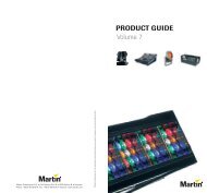
Mechanical Specifications12.5 in(31.8 cm)17.3 in(43.9 cm)2.56 in(6.5 cm)3.86 in(9.8 cm)25.6 in(65.1 cm)<strong>C|24</strong> side dimensions0.79 in(2 cm)0.45 in(1.16 cm)7.3 in(18.5 cm)39.4 in(100 cm)<strong>C|24</strong> back dimensionsChapter 1: Welcome to <strong>C|24</strong> 5
29.8 in(75.7 cm)40.9 in(104 cm)<strong>C|24</strong> top dimensions6<strong>C|24</strong> <strong>Guide</strong>
Connection RequirementsPower Connections<strong>C|24</strong> includes an external power supply that isauto power-selecting (90-250V, 50-60 Hz) andwill work automatically when plugged into anAC power receptacle in any country.Make sure your power source is correctly ratedfor all of the components of your system. Asurge-protected power source (not included) ishighly recommended.Ethernet Connections<strong>C|24</strong> communicates with Pro Tools usingEthernet. If <strong>C|24</strong> is the only Ethernet device you are usingwith your computer, you can connect it directlyto the Ethernet port on the computer. If you are using other Ethernet devices (suchas a connection to a Local Area Network) in additionto <strong>C|24</strong>, an Ethernet hub (not included) isrequired.Audio Connections The analog audio inputs and outputs for themic/line/DI preamplifiers and the monitoringsection, and the inputs for the built-in submixeron <strong>C|24</strong> are DB-25 connectors. Four alternate connectors for DI inputs , alternate(stereo) outputs for the monitoring section,and the outputs for the built-in submixer on<strong>C|24</strong> are 1/4-inch connectors.For more information on audio connections, seeAppendix A, “<strong>C|24</strong> Connector Pinouts.”Audio Cables for <strong>C|24</strong> MonitoringDigidesign offers a range of DigiSnake cablingoptions for connecting Digidesign interfacesand external sources to the <strong>C|24</strong>.For more information on DigiSnake audiocables, visit the Digidesign website(www.digidesign.com).Digidesign RegistrationReview the enclosed Digidesign Registration InformationCard and follow the instructions on itto quickly register your purchase online. Registeringyour purchase is the only way you can beeligible to receive complimentary technical supportand future upgrade offers. It is one of themost important steps you can take as a new user.Chapter 1: Welcome to <strong>C|24</strong> 7
About This <strong>Guide</strong>This guide explains how to install and makeconnections to your <strong>C|24</strong>, and how to use it toaccess Pro Tools features and commands.For complete information on using Pro Toolssoftware, refer to the guides included with yourPro Tools system.Conventions Used in This <strong>Guide</strong>Digidesign guides use the following conventionsto indicate menu choices and key commands::ConventionFile > SaveControl+NControl-clickRight-clickActionChoose Save from the FilemenuHold down the Control keyand press the N keyHold down the Control keyand click the mouse buttonClick with the right mousebuttonThe following symbols are used to highlight importantinformation:User Tips are helpful hints for getting themost from your system.Important Notices include information thatcould affect your data or the performance ofyour system.About www.digidesign.comThe Digidesign website (www.digidesign.com) isyour best source for information to help you getthe most out of your Pro Tools system. The followingare just a few of the services and featuresavailable.Registration Register your purchase online. Seethe enclosed Digidesign Registration InformationCard for instructions.Support Contact Digidesign Technical Supportor Customer Service; download software updatesand the latest online manuals; browse theCompatibility documents for system requirements;search the online Answerbase; join theworldwide Pro Tools community on the DigidesignUser Conference.Training and Education Become a certifiedPro Tools Operator or Expert; study on yourown using courses available online, or find outhow you can learn in a classroom setting at acertified Pro Tools Training Center.Products and Developers Learn about Digidesignproducts; download demo software; learn aboutour Development Partners and their plug-ins,applications, and hardware.News and Events Get the latest news fromDigidesign; sign up for a Pro Tools demo.To learn more about these and other resourcesavailable from Digidesign, visit the Digidesignwebsite (www.digidesign.com).Shortcuts show you useful keyboard ormouse shortcuts.Cross References point to related sections inthis guide and other Digidesign guides.8<strong>C|24</strong> <strong>Guide</strong>
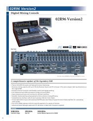
Chapter 2: <strong>C|24</strong> Overview<strong>C|24</strong> Top PanelMic/Line/DI Preamplifier controlsLine SubmixerMeter BridgeAuto EnableswitchesChannel BarLCD displaysRotary EncodersMonitorsectionMiscellaneouscontrolsAuto Write ToswitchesAuto ModeswitchesModifierswitchesTransport andNavigationcontrolsFader sectionFigure 1. <strong>C|24</strong> top panelChapter 2: <strong>C|24</strong> Overview 9
Meter BridgeThe Meter Bridge features a six-channel outputmeter, 24 pairs of channel meters, a Pro ToolsMain Counter display, and a built-in Talkbackmicrophone.Mic/Line/DI Preamplifier Controls<strong>C|24</strong> includes 16 analog Mic/Line preamplifiers,with phantom power capability and a switchablehigh-pass filter. Four channels have available1/4-inch inputs connectors that overridethe DB-25 inputs.Line Submixer<strong>C|24</strong> also includes an analog line submixer with8 stereo inputs and a stereo output that can beused to integrate analog studio equipment intoyour studio. The external output of the submixercan be can be routed to a Pro Tools audiointerface. Line submixer output can also berouted internally to the Monitoring section.Monitor SectionThe Control Room Monitor section providestwo selectable input sources, Main and Alt (bothsupporting up to 5.1 Surround); and two selectableoutputs, Main (supporting 5.1, LCRS or Stereomonitoring modes) and Alt (supporting Stereomonitoring only). It also provides Cue mixoutput, Studio LS output, and full Talkback andListenback capability to facilitate studio communication.Miscellaneous Controls<strong>C|24</strong> provides one-touch access to Pro Tools Editmodes, Edit tools, MIDI commands and operations,Pro Tools windows, Groups, Memory Locations,Window Configurations, and a range ofpowerful global controls that let you apply operationsto multiple tracks.Transport and Navigation Controls<strong>C|24</strong> gives you full control of Pro Tools transportfunctions with one-touch access to a rangeof audition functions, plus dedicated switchesfor multiple playback and recording modes. TheScrub /Shuttle wheel and Navigation key quadrantallow quick navigation of Pro Tools and the<strong>C|24</strong> Fader section.Channel BarThe Channel Bar provides powerful controls forviewing, assigning, and editing Inputs, Outputs,Inserts, Sends, Pan controls, plug-in parameters,Digidesitn PRE settings, and <strong>C|24</strong> settings, usingthe multipurpose LCD displays, and rotary encoders.LCD DisplaysThree multi-purpose 55x2 LCD displays provideaccess to a range of track information, ChannelBar functions, Soft Key commands, and <strong>C|24</strong> settings.Rotary EncodersTwenty-four multi-purpose rotary encoders letyou view and control volume and pan values,edit plug-in parameters, and make assignments.Automation Controls<strong>C|24</strong> includes dedicated controls for setting theautomation mode of individual channels, forenabling and suspending automation types, andsetting the global automation mode.Fader SectionTwenty-four 100mm touch-sensitive, motorizedfaders allow precise control and automation oftrack volume. Flip mode lets you control additionalPro Tools parameters from the faders.10<strong>C|24</strong> <strong>Guide</strong>
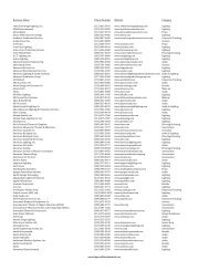
<strong>C|24</strong> Back PanelSubmixer section Preamps 9-16 section Preamps 1-8 sectionListen MicconnectorMonitor sectionExt Talk MicconnectorFigure 2. <strong>C|24</strong> back panelSubmixer SectionTwo DB-25 female connectors allow connectionof a total of 16 channels (8 stereo inputs). Stereooutput is available on 1/4-inch TRS connectors.Preamp SectionsEach of the two 8-channel preamp sections hastwo DB-25 female connectors that provide separate,switchable Mic and Line inputs, plus twoalternate 1/4-inch TRS connectors. A third DB-25 connector in each section provides preampoutputs.Monitor SectionFive DB-25 female connectors allow connectionof two six-channel inputs, two stereo inputs,and a pair of cue inputs. Outputs include a sixchannelMain output, stereo Alt Output (alsoavailable on 1/4-inch TRS connectors), stereo LSand Cue outputs, and a Talkback Slate output.FootswitchconnectorsListen Mic and External Talkback MicConnectorsTwo XLR microphone connectors allow connectionof a Listenback microphone and an optionalexternal Talkback microphone.Footswitch ConnectorsTwo 1/4-inch TRS footswitch connectors can beassigned independently to control Pro Tools recordingpunch in/out, Pro Tools transportstart/stop, or <strong>C|24</strong> talkback on/off.Ethernet Connector<strong>C|24</strong> communicates with Pro Tools usingEthernet. This connection uses a standard RJ45connector.Power Supply ConnectorEthernetconnectorPower Supplyconnector<strong>C|24</strong> comes with a dedicated external powersupply that connects to this port.Chapter 2: <strong>C|24</strong> Overview 11
12<strong>C|24</strong> <strong>Guide</strong>
Part II: Installation13
Chapter 3: Installing andConfiguring <strong>C|24</strong>Installing <strong>C|24</strong><strong>C|24</strong> can be set on a level table top or mountedin a console or desk.Wherever you install <strong>C|24</strong>, make sure not toblock air circulation to the vents on the back ofthe unit.Connecting Power to <strong>C|24</strong><strong>C|24</strong> comes with a dedicated external powersupply that has an IEC standard AC receptacle.This connector accepts a standard AC powercable.To connect power to <strong>C|24</strong>:1 Connect the external power supply to theconnector marked “To Ext PSU” on the backpanel of <strong>C|24</strong>. Make sure the connector is orientedcorrectly before securing the connection.2 Connect the included AC power cord to theexternal power supply.Connecting <strong>C|24</strong> to theComputer<strong>C|24</strong> communicates with Pro Tools usingEthernet. This connection uses a standard RJ45connector. If you are connecting <strong>C|24</strong> directly to yourcomputer, use a crossover Ethernet cable (one isincluded with <strong>C|24</strong>). If you are connecting <strong>C|24</strong> to an Ethernet hubor network, use a standard Ethernet cable (notincluded).If <strong>C|24</strong> will be the only Ethernet device connectedto your computer:1 Connect one end of the included crossoverEthernet cable to the Ethernet port on the backpanel of <strong>C|24</strong>.2 Connect the other end of the crossover Ethernetcable to the appropriate Ethernet port on thecomputer.3 Connect the other end of the AC power cordto a power source.Chapter 3: Installing and Configuring <strong>C|24</strong> 15
If you have more than one Ethernet device inaddition to <strong>C|24</strong>:1 Connect one end of a standard Ethernet cable(not included) to the Ethernet port on the backpanel of <strong>C|24</strong>.2 Connect the other end of the Ethernet cableto a powered Ethernet hub (do not use any portlabeled for LAN connection).3 Connect the Ethernet hub to the appropriateEthernet port on the computer.Shut down your system in this order:1 Turn off monitor amplifiers or self-poweredspeakers.2 Turn off all Pro Tools audio interfaces.3 Shut down the computer.4 If you are using MIDI equipment, turn offMIDI interfaces and other MIDI devices.5 Turn off the <strong>C|24</strong>.6 Turn off external hard drives.Starting Up and ShuttingDown a Pro Tools SystemYour <strong>C|24</strong>-based Pro Tools system should bestarted up and shut down in a specific order.Start your system in this order:1 Turn on external hard drives first. Wait 10 to15 seconds for them to come up to speed.2 Turn on the <strong>C|24</strong>.3 If you plan to work with MIDI equipment,turn on MIDI interfaces and other MIDI devices.4 Turn on all Pro Tools audio interfaces.5 Turn on the computer.6 Turn on monitor amplifiers or self-poweredspeakers.Configuring <strong>C|24</strong>All <strong>C|24</strong> software is included when Pro Toolssoftware is installed. The Pro Tools installerplaces the <strong>C|24</strong> Personality file in the Controllersfolder inside the Pro Tools folder.Refer to the Getting Started <strong>Guide</strong> that came withyour system for instructions on installing or updatingPro Tools software.Updating System FirmwareEach release of Pro Tools software includes current<strong>C|24</strong> firmware. When you declare a <strong>C|24</strong>unit in the Pro Tools Peripherals dialog,Pro Tools prompts you if a firmware update isavailable.If you are prompted to update firmware, followthe on-screen instructions to load the latestfirmware to the <strong>C|24</strong>.16<strong>C|24</strong> <strong>Guide</strong>
Establishing CommunicationBetween <strong>C|24</strong> and Pro ToolsCommunication between <strong>C|24</strong> and Pro Tools isconfigured by declaring the unit in Pro Tools.To declare <strong>C|24</strong> in Pro Tools:1 Choose Setup > Peripherals, and click EthernetControllers.Naming <strong>C|24</strong>You can set a name for a <strong>C|24</strong> unit, so that it canbe easily identified on a network shared withother Ethernet controllers. You can name <strong>C|24</strong>from Pro Tools, or directly from the unit inUtility Mode.To name <strong>C|24</strong> in Pro Tools:1 Choose Setup > Peripherals, and click EthernetControllers.2 Click Name Units. Any declared controllerswill appear in the Ethernet Controller Unitswindow.Ethernet Controllers page in the Peripheral dialog2 Select Enable. Pro Tools scans the Ethernetconnection for any Ethernet controllers connectedto the system.3 Select the <strong>C|24</strong> from the pop-up menu forController #1.If you are connected to a network, any Ethernetcontrollers available on the network will be displayedin the pop-up menu, as follows:Naming the <strong>C|24</strong>3 Enter the name for the <strong>C|24</strong> and click OK.4 For information on naming <strong>C|24</strong> from theunit, see “Unit Name” on page 116. Bold text indicates a connected unit. Italic text indicates an offline or disconnectedunit. Dimmed text indicates that the selected unitis in use by another Pro Tools system.4 Click OK to close the Peripherals dialog.When communication is established, Pro Toolsdisplays colored outlines identifying the tracksfocused on <strong>C|24</strong>.Chapter 3: Installing and Configuring <strong>C|24</strong> 17
Using Additional Control Surfaceswith <strong>C|24</strong>When a <strong>C|24</strong> is declared in Pro Tools, the use ofadditional control surfaces is subject to the followingrestrictions: You can use a MIDI-based control surface(such as a Digidesign Command|8) or anotherMIDI-based controller (such as the DigidesignSurround Panner Option) at the same time as a<strong>C|24</strong>. A MIDI control surface will mirror the first8 channels on <strong>C|24</strong>. You cannot use another Ethernet-based controlsurface (such as an ICON worksurface, Control|24,or ProControl) at the same time as a<strong>C|24</strong>. You cannot declare more than one <strong>C|24</strong> on aPro Tools system at a time.Setting <strong>C|24</strong> PreferencesThe following operational preferences for <strong>C|24</strong>are set from the unit, not from Pro Tools.Auto TalkbackYou can enable Auto Talkback, which automaticallyturns on the Talkback and Listen microphoneswhen the Pro Tools Transport isstopped. See “Auto Talkback” on page 118.Mic Pre Clip Hold TimeYou can set the Clip Hold time for the <strong>C|24</strong>built-in mic/line/DI preamplifiers. See “Mic PreClip Hold” on page 115.Footswitch FunctionYou can set the function and polarity for thetwo Footswitch connectors on <strong>C|24</strong>. See “FootswitchFunction and Polarity” on page 115.Console PreferencesYou can set the behavior of <strong>C|24</strong> displays andcontrols and how they interact with Pro Tools.See “Console Preferences” on page 45.External Talkback MicrophoneYou can choose to use an external Talkback microphoneinstead of the built-in Talkback microphonein the <strong>C|24</strong> Meter Bridge. See “ExternalTalkback Microphone” on page 114.Talkback LatchingYou can set Talkback to latch on when the Talkbackswitch is double-pressed. See “TalkbackLatching” on page 114.18<strong>C|24</strong> <strong>Guide</strong>
Chapter 4: Audio Connections<strong>C|24</strong> offers versatile analog audio features forrouting audio to and from Pro Tools and otheraudio equipment in your studio.The Mic/Line/DI preamplifiers, built-in LineSubmixer, and Monitor section operate independentlyof Pro Tools and can be used whenever<strong>C|24</strong> is powered on.Audio connectors for the built-in Mic/Line/DIpreamplifiers, Submixer, and Monitor sectionare provided on the back panel of <strong>C|24</strong>.This chapter provides a summary of the availableaudio connections to <strong>C|24</strong>. For detailed pinouttables, see Appendix A, “<strong>C|24</strong> ConnectorPinouts.” For example studio connections, seeChapter 5, “Connecting Your Studio.”Mic/Line/DI Preamplifiers<strong>C|24</strong> provides 16 Mic/Line/DI preamplifiers thatcan be used to route input signals to a Pro Toolsaudio interface for recording. The Mic/Line/DIinputs and outputs appear on the <strong>C|24</strong> backpanel in six DB-25 connectors.The Mic/Line/DI preamplifiers operate independentlyof Pro Tools and can be used whenever<strong>C|24</strong> is powered on.Mic/Line/DI Preamp InputsMic/Line Inputs <strong>C|24</strong> Mic/Line/DI preamplifierinputs appear in two groups of 8 balanced inputs(1-8, 9-16) on the back panel. Each group ofinputs has separate DB-25 female connectors formic level and line level inputs, labeled as follows:• Mic In 1-8• Line/DI In 1-8• Mic In 9-16• Line/DI In 9-16The input source (Mic or Line) can be selectedindividually for each channel using theMic/Line/DI preamplifier controls on the toppanel of <strong>C|24</strong>.Chapter 4: Audio Connections 19
Alternate 1/4-inch connectors <strong>C|24</strong> input channels1, 2, 9, and 10 also have altearnate 1/4-inchbalanced TRS connectors on the back panel, labeledas follows:• DI 1• DI 2• DI 9• DI 10When a source is plugged into a DI input(1, 2, 9, or 10), the corresponding Mic/Line input(1,2,9,or10) becomes unavailable.Mic/Line/DI preamplifier inputs are shown inthe following tables.Mic In 1-8ChannelSignal1 Mic In 12 Mic In 23 Mic In 34 Mic In 45 Mic In 56 Mic In 67 Mic In 78 Mic In 8Line In 1-8Channel Signal1 Line In 12 Line In 23 Line In 34 Line In 45 Line In 56 Line In 67 Line In 78 Line In 8DI In 1-2 (overrides Mic/Line In 1-2)Channel Signal1 Line In 12 Line In 2Mic In 9-16Channel Signal1 Mic In 92 Mic In 103 Mic In 114 Mic In 125 Mic In 136 Mic In 147 Mic In 158 Mic In 1620<strong>C|24</strong> <strong>Guide</strong>
Line In 9-16ChannelSignalLine OutputsLine Out 1-81 Line In 9ChannelSignal2 Line In 103 Line In 114 Line In 125 Line In 136 Line In 147 Line In 158 Line In 16DI In 9-10 (overrides Mic/Line In 9-10)1 Line Out 12 Line Out 23 Line Out 34 Line Out 45 Line Out 56 Line Out 67 Line Out 78 Line Out 8ChannelSignalLine Out 9-161 Line In 9ChannelSignal2 Line In 101 Line Out 92 Line Out 10Mic/Line/DI Preamp Outputs<strong>C|24</strong> Mic/Line/DI preamplifier outputs appearin two groups of 8 line-level outputs (1-8, 9-16)on the back panel. Each group of outputs has aDB-25 female connector, labeled as follows:• Line Out 1-8• Line Out 9-163 Line Out 114 Line Out 125 Line Out 136 Line Out 147 Line Out 158 Line Out 16Mic/Line/DI preamplifier outputs are shown inthe following tables.Chapter 4: Audio Connections 21
Line Submixer<strong>C|24</strong> provides an 8x2 line submixer that can beused to mix instrument inputs, auxiliary returns,or other external sources to stereo.The output of the Line Submixer can then beconnected to Pro Tools audio interface inputsfor recording, or it can be monitored throughthe Monitor section of <strong>C|24</strong>.The built-in Line Submixer operates independentlyof Pro Tools and can be used whenever<strong>C|24</strong> is powered on.Line Submixer Inputs<strong>C|24</strong> Line Submixer inputs appear as two groupsof 4 stereo inputs (1-4, 5-8) on the back panel.Each group of stereo inputs has a DB-25 femaleconnector, labeled as follows:• Submix In 1-4 (ST)• Submix In 5-8 (ST)Each of the 8 submixer inputs has an independentgain control on the top panel.Line Submixer input connections are shown inthe following tables.Submix In 1-4ChannelSignal1 Submixer Input 1 (Left)2 Submixer Input 1 (Right)3 Submixer Input 2 (Left)4 Submixer Input 2 (Left)5 Submixer Input 3 (Left)6 Submixer Input 3 (Right)Submix In 5-8ChannelSignal1 Submixer Input 5 (Left)2 Submixer Input 5 (Right)3 Submixer Input 6 (Left)4 Submixer Input 6 (Left)5 Submixer Input 7 (Left)6 Submixer Input 7 (Right)7 Submixer Input 84 (Left)8 Submixer Input 8 (Right)Line Submixer OutputsStereo Outputs <strong>C|24</strong> Line Submixer outputs appearas a pair of line-level outputs (L-R) on theback panel. Each output has a 1/4-inch balancedTRS connector, labeled as follows:• Submix Out L• Submix Out RSubmix Out 1-2ChannelSignal1 Submix Out (Left)2 Submix Out (Right)Stereo Output to Monitor Section <strong>C|24</strong> Submixeroutputs (L-R) can also be routed to theLeft and Right channels of the <strong>C|24</strong> Monitor sectionusing the “To Mon” switch on the toppanel of <strong>C|24</strong>. This useful for monitoring yourstudio equipment when you are not runningPro Tools.The submixer output level is controlled with theMaster level control on the top panel.7 Submixer Input 4 (Left)8 Submixer Input 4 (Right)22<strong>C|24</strong> <strong>Guide</strong>
Monitor SectionThe <strong>C|24</strong> Monitor section is a six-channel controlroom monitoring system that allows connectionof up to four input sources (two 6-channelor 4-channel surround, two stereo), two cueinputs, and two outputs (one 6-channel surroundand one stereo).Monitor section Inputs are connected toPro Tools audio interface outputs and other inputsources in your studio. Monitor section Outputsare connected to your speakers, cue system,headphones, and studio talkback and listenbacksystems.The Monitor section operates independently ofPro Tools and can be used to monitor other inputsources whenever <strong>C|24</strong> is powered on.Monitor Section Inputs<strong>C|24</strong> Monitor section inputs appear on threeDB-25 female connectors on the back panel, labeledas follows:• Pro Tools In (PT 1-6 + Cue 1-2)• Surround In (Alt Sur 1-6)• Ext Stereo In (Ext St 1 + St 2)Input sources can be selected individually orsummed using the Monitor source switches onthe top panel of <strong>C|24</strong>.Monitor section input connections are shown inthe following tables.Pro Tools In (PT 1-6 + Cue 1-2)Main Inputs Connect the outputs from yourPro Tools system to the Main Inputs.Cue Inputs Connect cue outputs from yourPro Tools system (such as a Send-based cue mixrouted to audio interface outputs) to the Cue Inputs.Pro Tools In (PT 1-6 + Cue 1-2)ChannelSignal1 Main Input Left (L)2 Main Input Center (C)3 Main Input Right (R)4 Main Input Left Surround (Ls)5 Main Input Right Surround (Rs)6 Main Input LFE (LFE)7 Cue Input Left8 Cue Input RightSurround In (Alt Sur 1-6)Alternate Surround Inputs Connect an alternateinput source (up to 5.1 surround) to the Alt Sur(Alternate Surround) Inputs.Surround In (Alt Sur 1-6)ChannelSignal1 Alt Input Left (L)2 Alt Input Center (C)3 Alt Input Right (R)4 Alt Input Left Surround (Ls)5 Alt Input Right Surround (Rs)6 Main Input LFE (LFE)7 (Unused)8 (Unused)Chapter 4: Audio Connections 23
Ext Stereo In (Ext St 1 + St 2)External Stereo Inputs Connect external stereosources (such as a DAT or CD player) to the ExternalStereo Inputs.Ext Stereo In (Ext St 1 + St 2)ChannelSignal1 Ext Stereo 1 In Left2 Ext Stereo 1 In Right3 Ext Stereo 2 In Left4 Ext Stereo 2 In Right5 (Unused)6 (Unused)7 (Unused)8 (Unused)Monitor Section Outputs<strong>C|24</strong> Monitor section outputs appear on twoDB-25 female connectors on the back panel, labeledas follows:• Control Room Out (5.1 Mon Out L:1 R:3)• Cue Outputs (Cue + SLS + TB)The Monitor section output mode can be set to5.1, LCRS, or Stereo using the Monitor modeswitches on the top panel of <strong>C|24</strong>.Control Room Out (5.1 Mon Out L:1 R:3)Main Outputs Connect the Main Outputs toyour primary studio monitors (tables are shownbelow for 5.1, LCRS and Stereo Main monitorsetups).Alternate Outputs Connect the Alternate Outputsto a secondary pair of studio monitors. TheAlt Outputs (L-R) are also available on 1/4-inchbalanced TRS connectors on the back panel, andmirror the output signal on the Alt Outputs onthe Control Room Out connector.Main Outputs (5.1) and Alternate OutputsControl Room Out (5.1 Mon Out L:1 R:3)ChannelSignal1 Main Output Left (L)2 Main Output Center (C)3 Main Output Right (R)4 Main Output Left Surround (Ls)5 Main Output Right Surround (Rs)6 Main Output LFE (LFE)7 Alt (Stereo) Output Left8 Alt (Stereo) Output RightMonitor section output connections are shownin the following tables.24<strong>C|24</strong> <strong>Guide</strong>
Main Outputs (LCRS) and Alternate OutputsControl Room Out (5.1 Mon Out)Channel Signal1 Main Output Left (L)2 Main Output Center (C)3 Main Output Right (R)4 Surround Output (S)5 (Unused)6 (Unused)7 Alt (Stereo) Output Left8 Alt (Stereo) Output RightMain Outputs (Stereo) and Alternate OutputsControl Room Out (5.1 Mon Out)Channel Signal1 Main Output Left (L)2 (Unused)3 Main Output Right (R)Cue Outputs (Cue + SLS +TB)Cue Outputs Connect the Cue Outputs to the inputsof your cue system.Studio LS Outputs Connect Studio LS Outputs tospeakers in your live room.Talkback Slate Output Connect the TalkbackSlate Output to an available Pro Tools input torecord slate information.Cue Outputs (Cue + SLS + TB)ChannelSignal1 Cue Out Left2 Cue Out Right3 Studio LS Out Left4 Studio LS Out Right5 Talkback Slate Out6 (Unused)7 (Unused)8 (Unused)4 (Unused)5 (Unused)6 (Unused)7 Alt (Stereo) Output Left8 Alt (Stereo) Output RightAlternate Outputs (Stereo)Alt Outputs (Alt Out L-R on 1/4-inch TRS connectors)ChanSignal1 Alt (Stereo) Output Left2 Alt (Stereo) Output RightChapter 4: Audio Connections 25
Listen and Talkback Microphones<strong>C|24</strong> provides connectors for a Listen microphoneand an optional External Talkback microphone.Listen Mic This XLR connector lets you connecta microphone to provide two-way communicationbetween the studio and the control room.External Talkback Mic This XLR connector letsyou connect an external microphone to use inplace of the built-in Talkback microphone. Talkbackinput is selected in the Talkback Preferencesin Utility mode. See “External TalkbackMicrophone” on page 114.For more infromation on the Talkback function,see “Talkback Switch” on page 57.Headphone Output<strong>C|24</strong> provides a headphone output with a 1/4-inch TRS connector on the front of the unit.Headphone source is switchable between ControlRoom outputs L and R (channels 1 and 3,pre-fader) and the Cue send (post-fader).26<strong>C|24</strong> <strong>Guide</strong>
Chapter 5: Connecting Your StudioConnection Examples forStereo MonitoringYou can set up a basic stereo monitoring systemusing 2-channel input from Pro Tools. This inputcan be monitored on channels 1 (Left) and 3(Right) of the <strong>C|24</strong> Main Monitor outputs, or inthe <strong>C|24</strong> Alt Monitor (Stereo) outputs.Another stereo source can be monitored by connectingit to channels 1 (Left) and 3 (Right) ofthe Alternate Surround Inputs.Additional stereo sources can be monitored byconnecting them to the External Stereo 1 and 2Inputs.You can also connect a separate cue send fromPro Tools, and route it to the <strong>C|24</strong> cue systemoutputs.The following tables and diagram show examplesof connections for stereo monitoring.Chapter 5: Connecting Your Studio 27
Monitoring System InputsMain Inputs and Cue InputsPro Tools In (PT 1-6 + Cue 1-2)Monitoring System OutputsMain Outputs (Stereo) and Alternate OutputsControl Room Out (5.1 Mon Out L:1 R:3)ChanSignalChanSignal1 Main Input Left (L) from Pro Tools Out 12 no connection3 Main Input Right (R) from Pro Tools Out 24 no connection5 no connection6 no connection7 Cue Input Left from Pro Tools Cue Out 18 Cue Input Right from Pro Tools Cue Out 2Alternate InputsSurround In (Alt Sur 1-6)Chan Signal1 Alt Input Left (L)2 no connection3 Alt Input Right (R)4 no connection5 no connection6 no connectionExternal Stereo Inputs1 Main Output Left (L) to Main speaker L2 no connection3 Main Output Right (R) to Main speaker R4 no connection5 no connection6 no connection7 Alt (Stereo) Output Left to Alt speaker L8 Alt (Stereo) Output Right to Alt speaker RAlt Outputs (Alt Out L-R on 1/4-inch TRS connectors)Chan Signal1 Alt (Stereo) Output Left to Alt speaker L2 Alt (Stereo) Output Right to Alt speaker RCue OutputsCue Outputs (Cue + SLS + TB)Channel Signal1 Cue Out Left to cue system2 Cue Out Right to cue systemExt Stereo In (Ext St 1 + St 2)ChanSignal1 Ext Stereo 1 In Left from CD player2 Ext Stereo 1 In Right from CD player3 Ext Stereo 2 In Left from DAT deck4 Ext Stereo 2 In Right from DAT deck28<strong>C|24</strong> <strong>Guide</strong>
Stereo Studio Connections(Example Setup)003RackPro ToolsStereo Out 1-2Cue Out 1-2CD playeror DAT deckPreamp Line Outto Pro ToolsSubmixerOutExt Stereo InLine Submixer InMic InLine InDI<strong>C|24</strong>Pro Tools InMonitor Alt OutHeadphone OutCue OutMonitorMain OutCh 1,3Alternate speakersCue systemMain speakersLRExample studio setup with stereo monitoringChapter 5: Connecting Your Studio 29
Connection Examples forSurround MonitoringYou can set up a surround monitoring systemusing up to 6-channel input from Pro Tools.5.1, LCRS, or Stereo input can be monitored inthe <strong>C|24</strong> Main Monitor outputs. Stereo inputcan also be monitored in the <strong>C|24</strong> Alt Monitor(Stereo) outputs.An additional surround source can be monitoredby connecting it to the Alternate SurroundInputs.External stereo sources can be monitored byconnecting them to the External Stereo 1 and 2Inputs.You can also connect a separate cue send fromPro Tools, and route it to the <strong>C|24</strong> cue systemoutputs.The following tables and diagram show examplesof connections for surround monitoring.30<strong>C|24</strong> <strong>Guide</strong>
Monitoring System InputsMonitor Inputs and Cue InputsPro Tools In (PT 1-6 + Cue 1-2)ChanSignal1 Main Input Left (L) from Pro Tools Out 12 Main Input Center (C) from Pro Tools Out 23 Main Input Right (R) from Pro Tools Out 34 Main Input L Surr (Ls) from Pro Tools Out 45 Main Input R Surr (Rs) from Pro Tools Out 56 Main Input LFE (LFE) from Pro Tools Out 67 Cue Input Left from Pro Tools Cue Out 18 Cue Input Right from Pro Tools Cue Out 2Alternate Surround InputsSurround In (Alt Sur 1-6)ChanSignal1 Alt Input Left (L) from DVD player2 Alt Input Center (C) from DVD player3 Alt Input Right (R) from DVD player4 Alt Input Left Surround (Ls) from DVDplayer5 Alt Input Right Surround (Rs) from DVDplayer6 Alt Input LFE (LFE) from DVD playerExternal Stereo InputsExt Stereo In (Ext St 1 + St 2)ChanSignal1 Ext Stereo 1 In Left from CD player2 Ext Stereo 1 In Right from CD player3 Ext Stereo 2 In Left from DAT deck4 Ext Stereo 2 In Right from DAT deckMonitoring System OutputsMain Outputs (5.1) and Alternate OutputsControl Room Out (5.1 Mon Out L:1 R:3)Chan Signal1 Main Output Left (L) to Left speaker2 Main Output Center (C) to Center speaker3 Main Output Right (R) to Right Speaker4 Main Output Left Surround (Ls) to LeftSurround speaker5 Main Output Right Surround (Rs) to RightSurround speaker6 Main Output LFE (LFE) to Subwoofer7 Alt (Stereo) Output Left to Alt speaker L8 Alt (Stereo) Output Right to Alt speaker RMain Outputs (LCRS) and Alternate OutputsControl Room Out (5.1 Mon Out L:1 R:3Chan Signal1 Main Output Left (L) to Left speaker2 Main Output Center (C) to Center speaker3 Main Output Right (R) to Right Speaker4 Main Output Left Surround (Ls) to Surroundspeaker (or split to 2 Surround speakers)5 no connection6 no connection7 Alt (Stereo) Output Left to Alt speaker L8 Alt (Stereo) Output Right to Alt speaker RAlternate Outputs (Stereo)Alt Outputs (Alt Out L-R on 1/4-inch TRS connectors)Chan Signal1 Alt (Stereo) Output Left to Alt speaker L2 Alt (Stereo) Output Right to Alt speaker RChapter 5: Connecting Your Studio 31
5.1 Surround Studio Connections(Example Setup)192 I/OPro ToolsCh 1-6 OutCue Out 1-2Ext Talkback& Listen MicsCD playeror DAT deckPreamp Line Outto Pro ToolsExt Stereo InLine Submixer InMic InLine InDI<strong>C|24</strong>Pro Tools InMonitor Alt OutHeadphone OutAltSurround InMonitorMain OutCh 1-6Alternate speakers4 1 2 35 6DVD playerL C RLs Rs LFEExample studio setup with 5.1 surround monitoring32<strong>C|24</strong> <strong>Guide</strong>
Part III: Reference33
Chapter 6: <strong>C|24</strong> Pro Tools ControlsFader SectionChannel StripAuto ModeindicatorsEQ switchInsert switchInput MonitorswitchAuto ModeswitchDyn switchSend switchLCD displayRotary EncoderEncoder switchRecord EnableswitchChannelSelect switchSolo switchMute switchFaderFaderEach channel has a touch-sensitive motorizedfader for controlling channel volume in Normalmode and a wide range of parameters in Flipmode. When you are automating a parameteron a fader in Touch mode, touching the faderstarts writing automation.Mute SwitchThe Mute switch toggles mute status for thechannel. When a track is muted, its Mute switchlights solid. When a track is implicitly muted(when another track is soloed), its Mute switchflashes.Solo SwitchThe Solo switch toggles solo status for the channel.When a channel is soloed, the Solo switchlights, and the Mute switches on other channelsin the session flash to indicate implicit mute.The Solo switch function follows the Pro ToolsSolo Latch options (Latch, X-OR, and Momentary).Solo Safe Mode To solo safe a track, hold theCommand/Ctrl Modifier switch and press thetrack’s Solo switch. When a track is solo safed,its Solo switch flashes once.Channel StripChapter 6: <strong>C|24</strong> Pro Tools Controls 35
Channel Select SwitchThe Channel Select switch selects the channel inPro Tools, and lights when the channel is selected.The Channel Select switch can be set tofollow latching or X-OR (non-latching) behavior.See “Console Preferences” on page 45.Input Monitor SwitchThe function of the Input Monitor switch dependson the type of track displayed in thechannel strip.Audio Tracks (Pro Tools HD Only) The InputMonitor switch toggles the input monitoringmode (TrackInput) for the channel betweenAuto Input and Input Only mode. When thechannel is in Input Only mode, the Input Monitorswitch lights.Instrument Tracks The Input Monitor switchtransfers control of MIDI Volume to the fader,MIDI Pan to the rotary encoder, and MIDI Muteto the channel Mute switch. It also changes Inputand Output assign modes to apply to MIDIInputs and Outputs on the Instrument track.When MIDI controls are displayed on the channelfader and encoder, the Input Monitor switchflashes.Record Enable SwitchThe Record Enable switch toggles record enablestatus for the channel. When a track is recordenabledand Pro Tools is idle or playing back,the Record Enable switch flashes. During recording,the Record Enable switch lights continuously.Record Safe Mode To record safe a track, holdthe Command/Ctrl Modifier switch and pressthe track’s Record Enable switch.Rotary Encoder SectionSelect/AutoswitchPre/PostswitchSend MuteswitchRotary Encoder sectionRotary EncoderEach Channel has a rotary encoder. The functionof the rotary encoders depends on the currentmode and view.Console Views Rotary encoders control channelpan, send level and assignments, depending onwhich Console view is enabled (Pan view orSends view). If your system includes a DigidesignPRE, mic pre level can be controlled fromthe rotary encoders in Console view.Channel View Rotary encoders control plug-in,pan, send, or plug-in settings and assignments,depending on which Channel view is enabled(Pan/Send view or Insert Select view). If yoursystem includes a Digidesign PRE, most mic precontrols can be accessed in Channel View.Flip Mode Rotary encoders control track Volumeor Send pan position when Flip mode is enabled.Rotary Encoder LEDsRotaryEncoderEncoderswitchEach rotary encoder has a ring of 11 LEDs for indicatingdata values controlled by the encoder.Discrete or stepped information such as pan positionor frequency is shown by a single LED.Continuously variable values such as send level,gain, or filter bandwidth is shown by an expandingseries of LEDs.36<strong>C|24</strong> <strong>Guide</strong>
Encoder LED rings can show send level, pan position,and plug-in parameter values. In Flipmode, they can show track level or Send pan position.Encoder SwitchThe switches under each encoder perform a varietyof functions, depending on what is shownin the LCD displays. Functions of the encoderswitch include:• Sends Console view: Toggling Send mute orSend pre/post status• Pan/Send Channel view: Toggling Sendmute or Send pre/post status• Parameter view: Cycling stepped plug-inparameters, setting up multi-mono plug-inoperation• Mic Pre view: If your system includes aDigidesign PRE, controlling mic pre settings• Groups view: Selecting Group IDs for newgroups, enabling or selecting currentGroups• Soft Keys view: Cycling preferences or performingactions• Default switch: Setting parameters to theirdefault values• Window Configuration view: Creating, editing,and recalling Window configurations• Memory Location view: Creating, editing,and recalling Memory LocationsSwitch Functions SectionThe Switch Functions section has three switchesthat set the function of the encoder switches incertain views.Select/Auto SwitchThe Select/Auto switch is available only when<strong>C|24</strong> is in Parameter view.Select When the Select/Auto switch is unlit, it isin Select mode. In this mode, encoder switchestoggle plug-in parameters displayed above thecorresponding encoder.Auto When the Select/Auto switch is lit, it is inAuto mode. In this mode, encoder switches doeither of the following:• If Pro Tools is idle or playing back, the encoderswitches enable the correspondingplug-in parameters for automation. Theswitch lights to indicate enabled status.• If an automation pass is in progress, the encoderswitches flash to indicate writing ofplug-in automation. You can press a flashingencoder switch to punch the plug-inparameter out of writing.Pre/Post SwitchThe Pre/Post switch is available only when <strong>C|24</strong>is in Sends Console view.When the Pre/Post switch is lit, the encoderswitches toggle the corresponding Send betweenpre- and post-fader operation. When the encoderswitch is unlit, the Send is set to post-faderoperation. When the encoder switch is lit, theSend is set to pre-fader operation.When you hold down the Pre/Post switch, thepre/post status of all Sends is displayed.Send Mute SwitchThe Send Mute switch is available only when<strong>C|24</strong> is in Sends Console view.When the Send Mute switch is lit, the encoderswitches toggle the mute status of the correspondingSend. When the encoder switch is unlit,the Send is not muted When the encoderswitch is lit, the Send is muted.To view the mute status of all displayed Sends,hold down the Send Mute switch.Chapter 6: <strong>C|24</strong> Pro Tools Controls 37
LED DisplaysDisplay ModeswitchLED displaysLED displays and Display Mode switchThe LED displays provide two rows of 6 charactersfor each channel strip.LED Display Mode SwitchTo cycle forward through LED display modes:• Press the Display Mode switch.To cycle backward through the LED displaymodes:• Hold the Shift (add) Modifier switch and pressthe Display Mode switch.The available display modes depends on the currentview.Home (Pan Console) ViewIn Pan Console view, the Display Mode switchcycles through the following channel displaymodes:Name Mode Shows the track name only on thetop row. Volume and Pan values are displayedon the bottom row when the fader is touched orthe encoder is moved, according to the TchValpreference.Volume Mode Shows the track name on the toprow and track volume on the bottom row.Mem Loc/Win Cfg Mode Shows the track nameon the top row and available Memory Locationsor Window Configurations on the bottom row.Sends Console ViewIn Sends Console view, the Display Mode switchcycles through the following Send displaymodes:Send Path Shows the track name on the top rowand the I/O or bus path for the Send on the bottomrow.Send Volume Shows the track name on the toprow and the Send volume on the bottom row.Blank Shows track name only on the top row.Channel InformationIn any view, you can also press and hold the DisplayMode switch to show channel state information,including current view display, LED displaydata, rotary and fader controls, and plug-ininformation.Insert SwitchInsert/SendBypassswitchInsert switchInsert switchEach channel has an Insert switch that lets youselect and view inserts on that channel. Theswitch lights to indicate that there is at least onenon-EQ, non-Dynamics plug-in on the channel.Pan Mode Shows the track name on the top rowand track pan on the bottom row.Headroom Mode Shows the track name on thetop row and track headroom on the bottom row.38<strong>C|24</strong> <strong>Guide</strong>
When you press a lit Insert switch, <strong>C|24</strong> goesinto Insert Select view, and displays the channel’sinserts across the LCD displays. From InsertSelect view, you can display all the controls of asingle plug-in in Parameter view. See “Insert SelectView” on page 76 and “Parameter View” onpage 78.In Parameter view, when you press and hold a litInsert switch, the LCD displays show informationon the currently focused insert.Insert/Send Bypass SwitchThe Insert and Send Bypass switch changes thefunction of the Insert switches on all channels,putting them in Bypass mode. When the Insert/SendBypass switch is lit, the Insert switchtoggles the Bypass state of all plug-ins on thechannel. In Bypass mode, when the plug-ins ona track are bypassed, the track’s Insert switch islit.See “Bypassing Plug-ins” on page 77.Send SwitchInsert/SendBypassswitchSend switchSend switchEach channel has a Send switch that lets you selectand view Sends on that channel.The switchlights to indicate that there is at least one Sendon the channel.When you press a lit Send switch, <strong>C|24</strong> goes intoPan/Send Channel view, and displays the channel’sSends across the LCD displays. See“Pan/Send Channel View” on page 71.When you double-press a Send switch, <strong>C|24</strong> goesinto Expanded Pan view, and displays the pancontrols for a track. See “Expanded Pan View”on page 73.Insert/Send Bypass SwitchThe Insert and Send Bypass switch changes thefunction of the Send switches on all channels,putting them in Bypass mode. When the Insert/SendBypass switch is lit, the Send switchtoggles the mute status of all Sends on the channel.In Bypass mode, when the sends on a trackare muted, the track’s Send switch is lit.See “Muting Sends in Pan/Send Channel View”on page 72.EQ and Dynamics SwitchesEQ/DynBypassswitchEQ and Dynamics switchesDyn switchEQ switchEach channel has EQ and Dynamics switchesthat let you focus any plug-ins of the correspondingtype assigned to that channel. The EQor Dyn switch lights to indicate that there is atleast one plug-in of the corresponding type onthe channel. When you press a lit EQ or Dynswitch, <strong>C|24</strong> goes into Parameter view, and displaysthe plug-in’s controls across the LCD displays.See “Viewing EQ and Dynamics Plug-ins”on page 79.In Parameter view, when you press and hold a litEQ or Dyn switch, the LCD displays show informationon the currently focused plug-in.Chapter 6: <strong>C|24</strong> Pro Tools Controls 39
EQ and Dynamics Bypass SwitchThe EQ and Dynamics Bypass switch changesthe function of the EQ and Dynamics switcheson all channels, putting them in Bypass mode:EQ Switch When the EQ and Dyn Bypass switchis lit, the EQ switch toggles the Bypass state of allEQ plug-ins on the channel. In Bypass mode,when the EQ plug-ins on a track are bypassed,the track’s EQ switch is lit.Dynamics Switch When the EQ and Dyn Bypassswitch is lit, the Dyn switch toggles the Bypassstate of all Dynamics plug-ins on the channel. InBypass mode, when the Dynamics plug-ins on atrack are bypassed, the track’s Dyn switch is lit.See “Bypassing EQ and Dynamics Plug-ins” onpage 79.See “Working with Automation” on page 100.The Automation Mode switch lets you cycle thechannel through Touch, Latch, Touch/Latch,Read and Off modes during playback, but it preventsyou from entering Write mode duringplayback. To directly enter Write mode duringplayback, use the Global Automation Modeswitch (See “Automation Mode Switches” onpage 40.)When in Write mode, the corresponding indicatorflashes at all times. When in Touch, Latch, orTouch/Latch modes, the corresponding indicatorlights until automation writing begins.When automation writing begins on the channel,the indicator flashes. If automation isturned off for the channel (Off), none of the indicatorsis lit.Channel Automation Mode Switch andIndicatorsGlobal Automation SwitchesAutomation Mode indicatorsAutomation Mode SwitchesAutomation Mode switchAutomation Mode switch and indicatorsEach channel has an Automation Mode switchand series of Automation Mode indicators(Write, Touch, Latch, Trim and Read).The Automation Mode switch cycles the channelthrough the following Pro Tools automationmodes:• Write• Touch• Latch• Touch/Latch (Pro Tools HD only)• Read• OffAutomationWrite ModeswitchAutomationTouch ModeswitchAutomationLatch ModeswitchAutomation Mode switchesAutomationTrim ModeswitchAutomationRead ModeswitchAutomationOffswitchThe Automation Mode switches are used to displayand set automation modes. These switcheslight to indicate that at least one channel is inthat automation mode. If multiple channels areselected and set to different automation modes,all applicable mode switches are lit.40<strong>C|24</strong> <strong>Guide</strong>
These Automation Mode switches mirror thefunction of the on-screen Automation Mode selectorfor each track, and let you change automationmodes of channels during playback.See “Working with Automation” on page 100.Write Switch Indicates or sets the automationmode of a track to Write mode.Touch Switch Indicates or sets the automationmode of a track to Touch mode.Latch Switch Indicates or sets the automationmode of a track to Latch mode.Trim Switch (Pro Tools HD Only) Indicates or setsthe automation mode of a track to Trim mode.Read Switch Indicates or sets the automationmode of a track to Read mode.Off Switch Sets the automation mode of a trackto Off.Automation Enable SwitchesWhen writing is enabled for an automation typebut it is not currently writing on any track in thesession, the corresponding switch lights solid.When writing is enabled for an automation typeand it is currently writing on any track in thesession, the corresponding switch flashes.Volume Switch Enables and suspends writing ofchannel volume automation on all tracks in thesession.Pan Switch Enables and suspends writing ofchannel pan automation on all tracks in the session.Mute Switch Enables and suspends writing ofchannel mute automation on all tracks in thesession.Send Level Switch Enables and suspends writingof send level automation on all tracks in the session.Send Pan Switch Enables and suspends writingof send pan automation on all tracks in the session.Enable VolumeAutomationswitchEnable PanAutomationswitchEnable MuteAutomationswitchSuspendAutomationswitchAutomation Enable switchesEnable Send LevelAutomationswitchEnable Send PanAutomationswitchEnable Send MuteAutomationswitchEnable Plug-inAutomationswitchSend Mute Switch Enables and suspends writingof send mute automation on all channels.Plug-in Switch Enables and suspends writing ofautomation for any automation-enabled plug-inparameters on all tracks in the session.Suspend Switch Suspends writing and playbackof all automation in the session.The Automation Enable switches are used to enableor suspend writing of each type of automationon all channels. These switches mirror thefunction of the corresponding buttons in theAutomation window.Chapter 6: <strong>C|24</strong> Pro Tools Controls 41
Automation Write To Switches(Pro Tools HD Only)Modifier SwitchesAutomationWrite to StartswitchAutomationWrite to PunchswitchAutomation Write To switchesAutomationWrite To AllswitchAutomationWrite To EndswitchAutomationWrite to NextswitchShift (add)switchControl/WinswitchModifier switchesOption/Alt (all)switchCommand/CtrlswitchThe Modifier keys duplicate the function of thePro Tools computer keyboard modifiers.The Automation Write To switches invoke themanual “Write to Start/End/All/Punch”commands and the automatic “Write toStart/End/All/Punch on Stop” automation commandsin Pro Tools. These switches mirror thefunction of the corresponding buttons in theAutomation window.See “Working with Automation” on page 100.All Switch Writes the current automation valueof all write-enabled parameters to an entire selectionor track when performing an automationpass.Start Switch Writes the current automationvalue of all write-enabled parameters to the startof a selection or track when performing an automationpass.End Switch Writes the current automation valueof all write-enabled parameters to the end of aselection or track when performing an automationpass.Punch Switch Writes the current automationvalue of all write-enabled parameters back to thepunch point (the location in the track where thecurrent automation pass started).Shift (add) Switch (Mac and Windows)The Shift (add) Modifier switch duplicates thefunction of the Shift key on the computer keyboard.Control (Mac) or Win (Windows) SwitchThe Ctrl/Win Modifier switch duplicates thefunction of the Control key (Mac) or the Windowskey, also called the Start key, (Windows)on the computer keyboard.Option (Mac) or Alt (Windows) SwitchThe Opt/Alt (all) Modifier switch duplicates thefunction or the Option key (Mac) or the Alt key(Windows) on the computer keyboard.Command (Mac) or Control (Windows) SwitchThe Command/Ctrl Modifier switch duplicatesthe function of the Command key (Mac) or theControl (Windows) key on the computer keyboard.Next Switch Writes the current automationvalue of all write-enabled parameters forward tothe next automation breakpoint.42<strong>C|24</strong> <strong>Guide</strong>
Channel BarThe Channel Bar spans the center of the Fader section of <strong>C|24</strong>, and includes controls for inserts, channelassignments, pan display, send display, and Soft Key functions.InsertssectionAssignsectionPansectionSoft KeysswitchSendssectionChannel BarScrollswitchesChannel BarInserts SectionCompareswitchMaster BypassswitchInserts section of the Channel BarMaster Bypass SwitchInsert/ParameterswitchSafeswitchThe Master Bypass switch bypasses plug-ins inone of two ways, depending on the currentview.Insert Select View The Master Bypass switch bypassesall plug-ins on the focused channel.Parameter View The Master Bypass switch bypassesonly the plug-in currently shown in theLCD displays.The Master Bypass switch lights to indicate thatthe currently displayed plug-in is bypassed. TheMaster Bypass switch flashes to indicate that atleast one channel of a currently displayed multimonoplug-in is bypassed.Compare SwitchThe Compare switch lets you compare any pluginchanges to the currently loaded plug-in settings.This mirrors the function of the Comparebutton in Pro Tools plug-in windows. The Compareswitch lights to indicate that controls on aplug-in have been changed but not saved as apreset.Safe SwitchThe Safe switch enables plug-in automation safemode for the currently displayed plug-in. TheSafe switch lights when an automation safedplug-in is focused.Insert/Parameter SwitchThe Insert/Parameter switch toggles the <strong>C|24</strong>view between Insert Select view and Parameterview, and accesses multi-mono plug-in setuppage. When an insert’s parameters are shown inthe LCD displays, the Insert/Param switchlights.See “Parameter View” on page 78 and “SettingUp Multi-mono Plug-ins” on page 79.Chapter 6: <strong>C|24</strong> Pro Tools Controls 43
Assign SectionPan SectionAssignswitchInputswitchOutputswitchEscape/CancelswitchWhen in Pan Console view or Pan/Send Channelview, the switches in the Pan section determinewhich pan controls are assigned to thechannel encoders. The corresponding pan, divergence,or percentage values are shown in theLCD displays.Assign section of the Channel BarAssign SwitchThe Assign switch puts <strong>C|24</strong> into Assign mode,which lets you assign inputs, outputs, inserts,and sends from the rotary encoders.See “Assign Mode” on page 85.Input and Output SwitchesThe Input and Output switches display channelinput and output pathnames in the bottom rowof the LCD displays.In Assign mode, the Input and Output switchesbring the inputs and outputs to the rotary encodersfor assignment.Escape/Cancel SwitchThe Escape/Cancel switch is used to exit modesand to cancel operations or on-screen dialogs.When an action has occurred that can be exitedor canceled with the Escape/Cancel switch, theswitch flashes.L(C)RswitchFront-RearswitchL(C)R SwitchThe L(C)R switch assigns Left-Right pan (stereotracks) or Front pan (multichannel tracks) to theencoder. When the Divergence switch is lit, thisswitch assigns Front divergence control to theencoder.Front-Rear SwitchThe Front-Rear switch assigns Front-Rear pan tothe encoder. When the Divergence switch is lit,this switch assigns Front-Rear divergence controlto the encoder.Rear SwitchRearswitchDivergenceswitchCenter %switchPan section of the Channel BarLFEswitchL/RswitchSoft KeysswitchThe Rear switch assigns Rear pan to the encoder.When the Divergence switch is lit, this switchassigns Rear divergence control to the encoder.Divergence SwitchThe Divergence switch puts the L(C)R, Front-Rear, and Rear switches into Divergence mode,which lets you adjust divergence for the correspondingparameters.44<strong>C|24</strong> <strong>Guide</strong>
Center Percentage SwitchThe Center Percentage (%) switch assigns theCenter Percentage parameter to the encoder.LFE SwitchThe LFE switch assigns LFE volume control tothe encoder.L/R SwitchThe L/R switch toggles display of the Left andRight pan control on the track’s encoder. WhenL/R switch is unlit, the track pan controls theLeft pan control (stereo tracks). When L/Rswitch is lit, the track pan controls the Right pancontrol (stereo tracks).Soft Keys SwitchThe Soft Keys switch provides access to <strong>C|24</strong>preferences, Pro Tools actions and Automationpreferences directly from the LCD displays.To set a preference or action from the Soft Keys:1 Press the Soft Keys switch.2 Press the encoder switch that corresponds tothe displayed item to cycle the preference settingor perform the command.3 Press the Soft Keys switch to exit.You can exit Soft Keys directly by enteringany other view or mode on <strong>C|24</strong>, except forMaster Faders mode. The Masters switchdoes not exit Soft Keys.The following console preferences, actions andand automation preferences are available:Console PreferencesFaders (Faders On/Off) Temporarily turns off<strong>C|24</strong> faders to prevent fader movement whenmonitoring a mix.TchVal (Touch Display of Parameter Values) Determinesthe temporary display of control parametervalues on a track when its fader istouched or its encoder is moved. TchVal can beset to the following:• On: All parameter values display when acontrol is touched• Off: Touch has no effect• NoVol: All parameter values except volumevalues display when a control is touchedSelect (Select Switch Latch Mode) Determineswhether channel Select switches follow latchingor X-OR (non-latching) behavior. When this preference is set to “Latch,” channelSelect buttons will latch on when pressed. When this preference is set to “X-OR,” pressinga channel Select switches disables otherchannel Select switches. To select multiplechannels in X-OR mode, press and hold multipleSelect switches.TkDsp (Track Display) Cycles the display of tracknames in the Console views to include Name(name only), Number (track position numberand an abbreviated name), or Grp ID (Group IDletter and an abbreviated track name).Chapter 6: <strong>C|24</strong> Pro Tools Controls 45
ChanWn (Channel Window Display) Determineswhether displaying plug-in or send parametersopens the corresponding plug-in or send windowon-screen in Pro Tools. When this preference is set to “Yes,” the onscreendisplay of plug-in and send windowschanges to reflect the state of the controlsurface. When this preference is set to “No,” the onscreendisplay of plug-in and send windows doesnot change to reflect the state of the controlsurface.2KbPan (Two-Knob Panning) (Pro Tools HD Only)Toggles linking of front and rear pan controls insurround panner windows to facilitate left-rightmotion in the surround field.Actions(Pro Tools HD Only)Prview (Preview) Puts Pro Tools in Previewmode.PchPrv (Punch Preview) Executes the Punch Previewcommand.Automation Preferences(Pro Tools HD Only)AutoJn (Auto Join) Sets tracks in Latch mode toautomatically resume writing of automation afterthe transport is stopped and started againduring an automation pass.LchStp (Allow Latch Prime in Stop) Toggles theAllow Latch Prime in Stop preference, which allowstracks in Latch mode to be primed for writingautomation while the transport is stopped.ColVCA (Coalesce when Removing Slaves fromVCA Group) Toggles the preference that automaticallycoalesces automation to slave trackwhen they are removed from a VCA-controlledgroup.ColTrm (Coalesce Trim Automation) Sets thepreference that determines when Trim automationis coalesced. The preference settings are asfollows:• EveryP: After Every Pass• OnExit: On Exiting Trim Mode• Manual: ManuallySusPrv (Preview Suspend) Suspends Previewmode.Captre (Capture) Executes the Capture command.PchCap (Punch Capture) Executes the PunchCapture command.Join Executes the Join command.46<strong>C|24</strong> <strong>Guide</strong>
Sends SectionThe Sends section switches are used in Consoleview to focus sends in the LCD displays. Sendvolume is controlled by the encoders.Miscellaneous ControlsEdit Mode SwitchesF-JswitchF-J switchThe F-J switch selects the bank of Sends accessiblefrom the Sends switches.When the F-J switch is off, the Sends switchescontrol Sends A through E. When the F-J switchis on, the Sends switches control Sends Fthrough J.Sends SwitchesSendsswitches (A-E/F-J)Sends section of the Channel BarThe Sends switches (A-E, F-J) are used to focus asingle Send position in the LCD displays, acrossall tracks. The switches light to indicate the currentlyfocused Send.ShuffleswitchEdit Mode switchesSpotswitchSlipswitchGridswitchThe Edit Mode switches place Pro Tools directlyin the corresponding Edit mode. The switchlights to indicate the current mode.Shuffle Switch Places Pro Tools in Shuffle mode.Spot Switch Places Pro Tools in Spot mode.Slip Switch Places Pro Tools in Slip mode.Grid Switch Toggles Pro Tools between Absoluteand Relative Grid mode.See “Selecting Edit Tools” on page 99.Channel Bar Scroll SwitchesThe Channel Bar Scroll switches are used tobank the display of parameters, sends, memorylocations, window configurations, or groups inthe LCD displays.The Channel Bar Scroll switches light when additionalparameters are available in the correspondingdirection.Chapter 6: <strong>C|24</strong> Pro Tools Controls 47
View and Edit SwitchesEdit SwitchesThe Edit switches directly execute the correspondingcommand in Pro Tools. The switcheslight to indicate which functions are available.HomeswitchView SwitchesHome SwitchFocusswitchView and Edit switchesMic PreswitchCopyswitchPasteswitchCopy and Paste SwitchesThe Copy and Paste switches carry out the Copyand Paste commands in the Pro Tools Editmenu.See “Cutting and Pasting” on page 99.Tools & Functions SwitchesThe Home switch puts <strong>C|24</strong> into Pan/Consoleview, which is the default view. In this view, faderscontrol channel volume, rotary encoderscontrol channel pan.See “Pan Console View” on page 69.Trim/All Notes OffGrabber/ClickSmart/Merge-RecLink Trk-Edit/Zoom TogFocus SwitchThe Focus switch returns <strong>C|24</strong> to the previouslyfocused view (Parameter view, Expanded Sendview, Expanded Pan view, or Mic Pre view) afteryou change to a Console view. The Focus switchlights to indicate that it is possible to return to afocused view.Mic Pre SwitchThe Mic Pre switch toggles <strong>C|24</strong> into Mic Preview, which shows the controls of any connectedDigidesign PRE.See “Mic Pre View” on page 80.Alt Function Select/Wait For NoteTools and Functions switchesAlternate Function SwitchThe Alternate Function switch selects the top orbottom command for the dual-functionswitches in this section. When the Alternate Function switch is off, thetop function is active for all switches in this section. When the Alternate Function switch is on, thebottom function is active for all switches in thissection.Edit ToolsPencil/Count OffLink Edit-TL/Tab to TrsntTrim Selects the Trim tool and cycles throughthe versions of the tool.Select Selects the Selector tool.48<strong>C|24</strong> <strong>Guide</strong>
Grabber Selects the Grabber tool and cyclesthrough the versions of the tool.Pencil Selects the Pencil tool and cycles throughthe versions of the tool.Smart Selects the Smart Tool.The Smart Tool can also be selected by simultaneouslypressing any combination of the Trim,Select, and Grabber switches.Link Edit and TimelineThe Link Edit and Timeline switch toggles theLink Timeline and Edit Selection option. Theswitch lights when the option is selected.Tab to TransientsThe Tab to Transients switch toggles the Tab toTransients option. The switch lights when theoption is selected.Zoom ToggleThe Zoom Toggle switch controls the Zoom Togglestate. The switch lights when Zoom Toggle isenabled.Window SwitchesLink Track and Edit SelectionThe Link Track and Edit Selection switch togglesthe Link Track and Edit Selection option. Theswitch lights when the option is selected.MIDI Commands and ControlsAll Notes Off Executes the All MIDI Notes Offcommand.Wait For Note Enables Wait for Note in theTransport window. The switch lights when Waitfor Note is enabled.Click Enables the Metronome Click in the Transportwindow. The switch lights when MetronomeClick is enabled.Count Off Enables the Countoff in the Transportwindow. The switch lights when Countoff is enabled.Merge-Record Enables MIDI Merge recording inthe Transport window. The switch lights whenMIDI Merge is enabled.Mix/WorkspaceAlt FunctionEdit/Task MgrWindow switchesPlug-in/Big CounterAlternate Function SwitchThe Alternate Function switch selects the top orbottom command for the dual-functionswitches in this section. When the Alternate Function switch is off, thetop function is active for all switches in this section. When the Alternate Function switch is on, thebottom function is active for all switches in thissection.Pro Tools WindowsPan/AutomationTransport/UndoWin Config/PropertiesMem Loc/MIDI OpsMix Opens the Mix Window or brings it to thefront.Edit Opens the Edit Window or brings it to thefront.Chapter 6: <strong>C|24</strong> Pro Tools Controls 49
Plug-in Opens and closes the window for the currentlyfocused plug-in.Global ControlsPan Opens and closes the window for the currentlyfocused pan controls.Transport The Transport switch opens and closesthe Transport window, and lets you show/hidesections of the Transport window. See “Displayingthe Transport Window” on page 91.Window Configuration The Window Configuration(Win Cfg) switch opens and closes the WindowConfiguration list and lets you display andselect Window Configurations in the LCD displays.See “Window Configuration View” onpage 82.Memory Locations The Memory Locations (MemLoc) switch opens and closes the Memory Locationswindow and lets you display and selectMemory Locations in the LCD displays. See“Memory Location View” on page 83.Workspace The Workspace switch opens andcloses the DigiBase Workspace Browser.Task Manager The Task Manager (Task Mgr)switch opens and closes the DigiBase Task Managerwindow.Big Counter The Big Counter switch opens andcloses the Big Counter window.Automation The Automation switch opens andcloses the Automation window.Undo The Undo switch opens and closes theUndo History window.Properties The Properties switch opens andcloses the MIDI Real-Time Properties window.Do To AllswitchDo ToSelectedswitchGlobal controlsDefaultswitchDo To All and Do To Selected SwitchesThe Do To All and the Do To Selected switchesare used to apply actions to multiple tracks in aPro Tools session.The Do To All and Do To Selected switches canfollow momentary or latching behavior. When single-pressed, their effect applies onlyto the next operation. When held, they apply to all operations carriedout while being held. When double-pressed, they latch on and flashuntil pressed a second time.Default SwitchSolo ClearswitchPlug-in SafeswitchVel SensswitchInput MonswitchMaster RecswitchThe Default switch is used to reset displayed parametersto their default values.The Default switch can follow momentary orlatching behavior. When single-pressed, its effectapplies only to the next operation. Whendouble-pressed, it latches on and flashes untilpressed a second time.MIDI Operations The MIDI Operations switchopens and closes the MIDI Operations window.50<strong>C|24</strong> <strong>Guide</strong>
Solo Clear SwitchGroupsThe Solo Clear switch clears all latched Soloswitches in the session. This switch flasheswhen any channel is soloed.Plug-in Safe SwitchThe Plug-In Safe switch enables plug-in automationsafe mode for the currently focused plug-in.This switch is lit when an automation safe pluginis focused.Velocity Sensitive SwitchThe Velocity Sensitive (Vel Sens) switch togglesall Rotary Encoders between fixed-velocitymode and velocity sensitive mode, where the responsivenessof the encoder is proportional tothe speed of rotation.Input Monitor SwitchPro Tools HDIn Pro Tools HD, the Input Monitor switch togglesthe Input Monitor option between “SetRecord Tracks to Auto Input” and “Set RecordTracks to To Input Only” on all record-enabledtracks.Pro Tools LEIn Pro Tools LE, the Input Monitor switch togglesPro Tools between Input Only Monitoringand Auto Input Monitoring.Master Record Enable SwitchThe Master Record Enable switch toggles recordenable status for all applicable audio tracks in asession. This switch flashes when channels arerecord-enabled and the Pro Tools transport isstopped, and lights continuously during recording.Groups switchesCreate SwitchThe Create switch lets you use <strong>C|24</strong> to select aGroup ID and select tracks to create newMix/Edit Groups. See “Creating Groups” onpage 81.Enable SwitchThe Enable switch lets you toggle the enabledstatus of current groups. See “Enabling and SuspendingGroups” on page 81.Modify SwitchThe Modify switch lets you use <strong>C|24</strong> to modifyMix/Edit groups. See “Modifying Groups” onpage 82.Delete SwitchThe Delete switch executes the Delete Groupscommand. See “Deleting Groups” on page 82.Suspend SwitchCreate Groups switchEnable Groups switchModify Groups switchDelete Groups switchSuspend Groups switchDeleting groups cannot be undone.The Suspend switch suspends all groups in thesession.Chapter 6: <strong>C|24</strong> Pro Tools Controls 51
Transport and NavigationControlsTransport Mode SwitchesPre-Roll Switch Plays audio starting at the prerollpoint up to the beginning of the selection.Mark In Switch Plays audio starting at the selectionstart through the length of the post-rollamount.Mark Out Switch Plays audio back-timed fromthe selection end by the pre-roll amount.AuditionswitchPre-RollswitchDyn TransswitchAudition SwitchRTZ/EswitchTransport Mode switchesTrans=switchOnlineswitchMark In Post-Rollswitch switchMark OutswitchLoop PlaybackswitchLoop RecordswitchQuickPunchswitchThe Audition switch toggles Audition mode onand off. When Audition mode is on, this switchlights.In Audition mode, you can listen to either thestart or end of a selection, with or without prerollor post-roll, by pressing the followingswitches:Post-Roll Switch Plays audio starting at the endof a selection through the post-roll amount.Return to Zero/Go To End SwitchThe Return to Zero/Go To End switch locates thecursor to the beginning or the end of the session.See “Navigating with the Transport” onpage 97.Transport Master SwitchThe Transport Master (Transport =) switch cyclesthe Transport Master through the availableoptions, which can include Pro Tools, Machine,MMC, or Remote. The Transport Equals switchlights when the Transport Master is set to Machine,MMC, or Remote.Online SwitchThe Online switch toggles the Pro Tools transportonline status when triggering playbackfrom an external source. The Online switchflashes when the transport is waiting for sync,and lights to indicate that the transport is online.Pre-Roll and Post-Roll SwitchesThe Pre-Roll and Post-Roll switches toggle theenable status of pre-roll and post-roll in thePro Tools transport. The Pre-Roll and Post-Rollswitches light to indicate they are enabled.52<strong>C|24</strong> <strong>Guide</strong>
In Audition mode, the Pre-Roll and Post-Rollswitches activate playback of various parts of anedit selection. See “Audition Switch” onpage 52.Mark In and Mark Out SwitchesIn Audition mode, the Mark In and Mark Outswitches activate playback of various parts of anedit selection, and in conjunction with theScrub/Shuttle wheel, let you create selections.See “Selecting Audio” on page 96.Dynamic Transport SwitchThe Dynamic Transport switch toggles DynamicTransport mode on and off.Loop Playback SwitchThe Loop Playback switch toggles Loop Playbackmode on and off. The Loop Playback state is mirroredin the Play button in the Pro Tools Transportwindow. When Loop Playback mode is active,this switch lights.Loop Record SwitchThe Loop Record switch toggles Loop Recordmode on and off. The Loop Record state is mirroredin the Record button in the Pro ToolsTransport window. When Loop Record mode isactive, this switch lights.QuickPunch SwitchThe QuickPunch switch toggles QuickPunchrecord mode on and off. When QuickPunchmode is active, this switch lights. The Quick-Punch state is mirrored in the Record button inthe Pro Tools Transport window.Zoom Preset SwitchesZoom Preset 1Zoom Preset 3Zoom Preset 5Zoom Preset switchesThe Zoom Preset switches let you set and recallthe five horizontal Zoom presets in Pro Tools.File/Utility SwitchesUndoswitchRedoswitchFile/Utility switchesUndo SwitchThe Undo switch executes the Undo commandin Pro Tools.Redo SwitchEnterswitchThe Redo switch executes the Redo command inPro Tools.Utility SwitchEsc/CancelswitchSaveswitchZoom Preset 2Zoom Preset 4UtilityswitchThe Utility switch places <strong>C|24</strong> in Utility mode.When <strong>C|24</strong> is in Utility mode, this switchflashes.Chapter 6: <strong>C|24</strong> Pro Tools Controls 53
Utility mode lets you view <strong>C|24</strong> system information,run diagnostic tests, and set certain <strong>C|24</strong>preferences. For complete information, seeAppendix B, “Utility Mode.”Enter SwitchThe Enter switch is used to confirm operations,and is equivalent to clicking OK in Pro Tools dialogs.The Enter switch is also used to create newMemory Locations, and is equivalent to the Enterkey on the computer numeric keypad.Esc/Cancel SwitchThe Escape/Cancel switch is used to exit modesand to cancel operations or on-screen dialogs.When an action has occurred that can be exitedor canceled with the Escape/Cancel switch, theswitch flashes.Save SwitchThe Save switch executes the Save Session commandin Pro Tools. Whenever a change is madein a session and the Save command is available,this switch lights.Zoom/Navigate SwitchesZoom ModeswitchNavigate ModeswitchArrow switchesZoom SwitchThe Zoom switch puts the Arrow switches inZoom mode.Navigate SwitchThe Navigate switch puts the Arrow switches inNavigate mode.Arrow SwitchesThe function of the Arrow switches depends onthe current mode.Zoom Mode In Zoom Mode, the Up and DownArrow switches change the vertical zoom andthe Previous (Left) and Next (Right) Arrowswitches change the horizontal zoom in thePro Tools Edit window.Navigate Mode In Navigate mode, the Up andDown Arrow switches move the edit cursor orselection up and down among tracks, and thePrevious (Left) and Next (Right) Arrow switchesmove the edit cursor left and right among regionboundaries or transients (according to theTab to Transients setting).Pro Tools Window Text Entry In both Zoom orNavigate modes, the Arrow switches can be usedto navigate on-screen text fields.Dialog Box Navigation In Pro Tools, the Arrowswitches can be used to navigate through foldersin dialog boxes such the Open Session dialog.Edit Window Navigation In the Edit window, theArrow switches let you page the Edit windowforward and backward.Zoom/Navigate switches54<strong>C|24</strong> <strong>Guide</strong>
Scrub/Shuttle ControlsBank/Nudge SwitchesTrim switchScrubswitchShuttleswitchScrub/ShuttlewheelBank LeftswitchBank RightswitchScrub/Shuttle controlsScrub/Shuttle WheelThe Scrub/Shuttle wheel is used for cursor location,scrubbing, zooming, window navigation,and banking faders.Scrub SwitchThe Scrub switch places the transport in Scrubmode, which lets you scrub from the cursor positionor across a selection.Trim Switch(Pro Tools HD Only)The Trim switch places the transport inTrim/Scrub mode, which lets you scrub to locatean edit point, then trim to that point.Nudge switchBank/Nudge switchesBank SwitchesThe Bank switches move the display of tracks on<strong>C|24</strong> to the left or to the right 24 channels at atime. If the “Mix/Edit Window Follows Bank Selection”option is selected, the Pro Tools onscreendisplay moves to mirror the track displayon <strong>C|24</strong>.Nudge SwitchThe Nudge switch, used with the Bank switches,moves the display of tracks on <strong>C|24</strong> to the left orto the right one channel at a time. If the“Mix/Edit Window Follows Bank Selection” optionis selected, the Pro Tools on-screen displaymoves to mirror the track display on <strong>C|24</strong>.Shuttle Switch(Pro Tools HD Only)The Shuttle switch places the transport in Shuttlemode, which lets you scrub at several timesnormal speed.Chapter 6: <strong>C|24</strong> Pro Tools Controls 55
Transport SwitchesMasters SwitchMasters switchFast ForwardswitchRewindswitchTransport switchesStopswitchPlayswitchRecordswitchThe <strong>C|24</strong> Transport switches correspond to thebuttons in the Pro Tools Transport window.Rewind Switch Moves backward through thePro Tools session beginning from the currentcursor position, as long as the switch is held.Fast Forward Switch Moves forward through thePro Tools session beginning from the currentcursor position, as long as the switch is held.Stop Switch Stops playback of the Pro Tools session.Masters switchThe Masters switch cycles temporary display ofMaster Fader tracks and VCA Master tracks(Pro Tools HD only) to the right side of the <strong>C|24</strong>faders. The Masters switch flashes to indicatedisplay of Master Faders or VCA Master tracks.Flip SwitchFlip switchPlay Switch Begins playback of the Pro Tools sessionfrom the current cursor position.Record Switch Arms Pro Tools for recording. Theexact function depends on the current Pro Toolsrecord mode (QuickPunch, TrackPunch, Waitfor Note, Pause).See “Navigating with the Transport” on page 97.Flip switchThe Flip switch invokes Flip mode. Flip modetransfers control assignments from rotary encodersto the channel faders, which lets you usethe touch-sensitive faders to edit and automatepan, send, PRE, and plug-in parameter values.The Flip switch flashes to indicate Flip mode.You can enter Assign mode while in Flip mode,and use the faders (instead of the encoders) toscroll through lists when assigning inputs, outputs,inserts and sends.See “Flip Modes” on page 84.56<strong>C|24</strong> <strong>Guide</strong>
Talkback SwitchMeter BridgeMeters and Counter DisplayMain CounterOutput MetersTalkback switchTalkback switchThe Talkback switch activates the Talkback microphone.The Talkback switch lights to indicatethat Talkback is active. Talkback signal issummed with the Cue inputs and also sent tothe Slate output. For more information on Talkbacksignal routing, see “Monitor Section” onpage 23.Talkback level is set with the Talkback controlsin the Monitor section. See “Talkback LevelKnob and Switch” on page 61.You can set Talkback to stay on only when held,or to latch on if rapidly double-pressed. See“Talkback Latching” on page 114.You can set the Talkback and Listen microphonesto turn on automatically when thePro Tools Transport is stopped, and turn offwhen the Pro Tools Transport is running. See“Auto Talkback” on page 118.In addition to the Talkback switch, you can controlTalkback with a footswitch connected to<strong>C|24</strong>. See “Footswitch Connectors” on page 11and “Footswitch Function and Polarity” onpage 115.Talkback microphoneCounter switchMain Counter and Output MetersOutput MetersThe right side of the <strong>C|24</strong> meter bridge has agroup of six 14-segment LED bar graph metersfor displaying output levels.Stereo OutputIn a standard configuration, the Output metersshow stereo output on channels 1 and 3.Multichannel Output (Pro Tools HD Only)The Output meters show multichannel outputup to 5.1 Surround. The meters always displayoutput in this order: L, C, R, Ls, Rs, LFE.Main CounterThe Main Counter mirrors the display of theMain Time Scale in Pro Tools.Chapter 6: <strong>C|24</strong> Pro Tools Controls 57
Time Display Format IndicatorsThe indicator to the left of the Main Countershows the currently displayed time scale format.Formats include:• Hours:Minutes:Seconds:Milliseconds• Hours:Minutes:Seconds:Frames• Feet+Frames• Bars|Beats• Samples (all indicators off)Counter SwitchThe left side of the <strong>C|24</strong> meter bridge has 24pairs of 14-segment LED bar graphs for displayingtrack levels. These meters can display pre- orpost-fader levels, depending on the state of theMeters Post switch.Mono tracks use only the left side of the LEDpair on a channel. Stereo and multichannel(Pro Tools HD only) tracks use both sides of theLED pair on a channel.Meter ControlsThe Counter switch cycles the Main Counter on<strong>C|24</strong> (and on-screen in Pro Tools) through thetime scale formats currently displayed in thePro Tools Edit window.Clear ClipswitchMeters PostswitchTo cycle the Main Counter through all timeformats:• Hold Option/Alt (all) while pressing theCounter switch.Talkback MicrophoneThe <strong>C|24</strong> built-in Talkback microphone is activatedby the Talkback switch. The output for thebuilt-in Talkback microphone appears in theCue Outputs connectors.Channel MetersClear Clip switch and Meters Post switchClear Clip SwitchThe Clear Clip switch on the left-hand side of<strong>C|24</strong> clears clip indications on all channel andoutput meters on <strong>C|24</strong> and all meters inPro Tools, and in Pro Tools HD, any plug-in clipindications. The Clear Clip switch lights to indicateclipping anywhere in the Pro Tools session.Meters Post SwitchThe Meters Post switch toggles the ChannelMeters between pre-fader and post-fader operation.This switch mirrors the state of the PreandPost-Fader Metering options in Pro Tools.The Meters Post switch lights when channelmeters are set to post-fader operation.Channel Meters58<strong>C|24</strong> <strong>Guide</strong>
Chapter 7: <strong>C|24</strong> Analog Audio ControlsMonitor SectionThe Monitor section includes controls for 6-channel control room monitoring, 2-channel studioloudspeaker and cue system routing, headphone output, and listenback and talkback input.Output ModeswitchOutput ModePreset IndicatorsControl Room Main OutputswitchesSoloswitchControl RoomencoderHeadphonelevel knobSolo LSlevel knobCuelevel knobListen Miclevel knobTalkbacklevel knobAlt MonitorswitchFrom CueswitchStudio LSswitchMain>CueswitchListen MicswitchMuteswitchDimswitchMonoswitchMainswitchAlt SurswitchStereo 1switch Stereo 2switchSumswitch<strong>C|24</strong> Monitor sectionChapter 7: <strong>C|24</strong> Analog Audio Controls 59
Output ModeswitchOutput ModePreset IndicatorsControl Room Main OutputswitchesSoloswitch<strong>C|24</strong> Monitor section (top)Output Mode Switch and Indicators<strong>C|24</strong> has three preset monitor modes availablefor the Control Room Main Outputs:• Stereo (L,R)• LCRS• 5.1 (L, C, R, Ls, Rs, LFE)The Output Mode switch cycles through thesethree preset modes. When any of these preset modes is selected,its indicator lights, and the corresponding MainOutput switches light. When any of these preset modes is selectedand any of its outputs are disabled, or any additionaloutputs are enabled, the indicator flashes.Stereo Mode In Stereo mode, only the Left (L)and Right (R) output channels of the ControlRoom Main Outputs are active, even whenmonitoring a surround input source. No summingof the surround channels occurs.LCRS Mode In LCRS mode, the Left (L), Center(C), Right (R), and Left Surround (Ls) channelsare active. In this mode, the Left Surround (Ls)input is routed to both the Left Surround (Ls)and Right Surround (Rs) outputs.5.1 Mode In 5.1 mode, all output channels areactive.Control Room Main Output SwitchesThe Control Room Main Output switches enablethe corresponding output channels. Youcan enable any combination of channels at atime.An output switch lights to indicate that thechannel is enabled.The switches are as follows:• L (Left)• C (Center)• R (Right)• Ls (Left Surround)• Rs (Right Surround)• LFE (Low Frequency Effect)Solo SwitchThe Solo switch puts the Main Output switchesin Solo mode, which lets you solo output channelsby pressing the corresponding switch. TheSolo switch lights to indicate Solo mode is active.When you first enter Solo mode, all currentlyenabled Main Output switches remain active,until you press a switch to solo it.60<strong>C|24</strong> <strong>Guide</strong>
Control RoomencoderHeadphonelevel knobStudio LSlevel knobCuelevel knobListen Miclevel knobTalkbacklevel knobAlt MonitorswitchFrom CueswitchStudio LSswitchMain>CueswitchListen Micswitch<strong>C|24</strong> Monitor section (middle)Control Room Encoder and LEDsThe Control Room encoder controls the outputvolume for the Main and Alt outputs. The encoderLEDs show Gain graphically, and the LCDdisplays show Gain values (in dB).Alt Monitor SwitchThe Alt Monitor switch routes the Left and Rightchannels to the Alt Outputs, and deactivates theC, Ls, Rs, and LFE channels. When the Alt Monitoroutputs are active, this switch is lit. Whenthe Main Monitor outputs are active, this switchis unlit.Headphone Level KnobThe Headphone level knob controls volume tothe built-in headphone output. The headphoneoutput is fed by the Left and Right ControlRoom Main outputs (channels 1 and 3).From Cue SwitchThe From Cue switch routes the Cue output tothe headphones (post Cue level control) and disablesthe feed from the Main output. The FromCue switch lights to indicate that the Cue routingis active.Studio LS Level Knob and SwitchThe Studio LS level knob controls volume to theStudio LS outputs. The Studio LS switch activatesthe Studio LS output, and lights to indicatethat the Studio LS is on.Cue Level Knob and Main to Cue SwitchThe Cue level knob controls volume to the Cueoutputs. The Main to Cue switch routes the Leftand Right Control Room outputs to the Cue outputsand disables the feed from the Cue input.The Main to Cue switch lights to indicate thatthe routing is active.Listen Mic Level Knob and SwitchThe Listen Mic level knob controls gain for theListen microphone, which feeds the Main output.The Listen Mic switch activates Listenback,and lights when Listenback is on.Talkback Level Knob and SwitchThe Talkback level knob controls gain for theTalkback microphone. Talkback signal issummed with the Cue inputs and also sent tothe Slate output. Talkback is activated by theTalkback switch in the Transport section.Chapter 7: <strong>C|24</strong> Analog Audio Controls 61
MuteswitchDimswitchMonoswitchMainswitchAlt SurswitchStereo 1switch Stereo 2switchSumswitch<strong>C|24</strong> Monitor section (bottom)Master Control Room OutputControlsMute SwitchThe Mute switch mutes all Control Room monitoroutputs (Main and Alt), but does not muteHeadphone, Cue, and Studio LS outputs. TheMute switch lights to indicate that ControlRoom outputs are muted.Dim SwitchThe Dim switch applies an adjustable gain reductionto all Control Room monitor outputs(Main, Alt, and Stereo 1 and 2), but does not affectHeadphone, Cue, and LS outputs. The defaultgain reduction amount is 20 dB. Dim is automaticallyengaged when Talkback is engaged.The Dim switch lights to indicate that ControlRoom outputs are dimmed.Mono SwitchThe Mono switch sums the Left and Right ControlRoom outputs (Main, Alt and Stereo 1and 2), deactivates the C, Ls, Rs, and LFE channels,and lowers monitor output by an adjustableamount. The default gain reduction is 6 dB.Headphone, Cue, and LS outputs are not affected.The Mono switch lights to indicate thatit is active.Control Room Input SelectorsControl Room Input selections are mutually exclusive(X-OR) unless the Sum switch is engaged,when they are additive.Main SwitchThe Main switch routes the Main Surround input(Pro Tools In 1-6) to the Control Room outputs.The Main switch lights to indicate that it isactive.Alt Sur SwitchThe Alt Sur switch routes the Alternate Surroundinput (Surround In 1-6) to the Control Roomoutputs. The Alt Sur switch lights to indicatethat it is active.Stereo 1 and Stereo 2 SwitchesThe Stereo 1 and Stereo 2 switches route the ExternalStereo inputs (Ext St 1 and Ext St 2) to theControl Room outputs.These stereo inputs appear in the Left and RightControl Room output channels only and are excludedfrom the C, Ls, Rs, and LFE channels.The Stereo 1 and Stereo 2 switches light to indicatethat they are active.62<strong>C|24</strong> <strong>Guide</strong>
Sum SwitchThe Sum switch causes Control Room Inputs tobe additive instead of mutually exclusive(X-OR). When active, the Sum switch temporarilybypasses any Trim values currently appliedto any of the inputs.The Sum switch latches on, allowing you to selectthe inputs to be summed. The Sum switchlights to indicate that it is active.Monitoring AFL/PFL Signals(Pro Tools HD Only)If you are working on a stereo session, you canmonitor soloed tracks in AFL or PFL Solo modeby routing the AFL/PFL path to one of the <strong>C|24</strong>External Stereo inputs and summing that Stereoinput with the <strong>C|24</strong> Main input.To monitor AFL/PFL signals:1 Connect an unused pair of outputs on youraudio interface to one of the External Stereo inputson <strong>C|24</strong>.2 In the Pro Tools I/O Setup window, select thepair of audio interface outputs as the AFL/PFLoutput path.3 Select the Main output path to be mutedwhen you solo a track in AFL or PFL mode.4 In the Monitor section of <strong>C|24</strong>, press the Sumswitch so that it is active.5 Activate the Main input and the External stereoinput.When AFL or PFL Solo mode is selected and atrack is soloed, the Main input is muted and theAFL/PFL signal is heard on the External Stereoinput.Submixer OutputWhen the To Monitor switch in the Line Submixercontrols is engaged, the stereo outputfrom the Submixer is routed internally and automaticallysummed with the Left and Rightchannels of the current Control Room Input selection,and are excluded from the C, Ls, Rs, andLFE channels. Any Trim values applied to thecurrent input are also applied to the summedSubmixer output.Trimming Monitor Section GainControlsThe gain controls in the Monitor section can beadjusted to establish channel balance and levelmatching between inputs.Control Room Main OutputsEach of the Control Room Output channels canbe trimmed individually. Available trim valuesrange from –30 dB to +10 dB, in 0.5 dB steps.To trim the level for an individual output channel:1 Hold the Output Channel switch until theswitch flashes. The channel name and Trimamount appear in the right side of the LCD displays.2 Turn the Control Room encoder to adjust theTrim amount.3 Press the flashing Output Channel switch toconfirm the change, or press any other switch inthe Monitor section to cancel the change.4 Repeat the above steps for each output channelyou want to trim.Chapter 7: <strong>C|24</strong> Analog Audio Controls 63
Control Room Alt OutputsThe Control Room Alt Outputs can be trimmedrelative to the Main Output to compensate fordifferences between speaker systems. The Leftand Right channels of the Alt Output can also betrimmed relative to each other.To trim the overall level of the Alt Outputs:1 Hold the Alt Mon switch until the switchflashes. The Trim amount appears in the rightside of the LCD displays. Available trim valuesrange from –30 dB to +6 dB, in 0.5 dB steps.2 Turn the Control Room encoder to adjust theTrim amount.3 Press the flashing Alt Mon switch to confirmthe change, or press any other switch in theMonitor section to cancel the change.To trim the level for the Left or Right Alt Output:1 Press the Alt Mon switch so that the Alt MonOutput is selected (the switch it lit).2 Hold the Left or Right Output Channel switchuntil the switch flashes. The channel name andTrim amount appear in the right side of the LCDdisplays.3 Turn the Control Room encoder to adjust theTrim amount.4 Press the flashing Output Channel switch toconfirm the change, or press any other switch inthe Monitor section to cancel the change.Control Room Output Dim FunctionThe Dim switch applies an adjustable gain reductionto all Control Room monitor outputs.The amount of Dim gain reduction can be setwhile in any monitoring mode.To set the amount of Dim gain reduction:1 Hold the Dim switch until the switch flashes.The Dim amount appears in the right side of theLCD displays.2 Turn the Control Room encoder to adjust theDim amount.3 Press the flashing Dim switch to confirm thechange, or press any other switch in the Monitorsection to cancel the change.Control Room Output Mono FunctionThe Mono switch sums the Left and Right ControlRoom outputs and lowers monitor outputby an adjustable amount. The amount of Monolevel reduction can be set while in any monitoringmode.To set the amount of Mono level reduction:1 Hold the Mute switch until the switch flashes.The Dim amount appears in the right side of theLCD displays.2 Turn the Control Room encoder to adjust theMono level reduction amount.3 Press the flashing Mono switch to confirm thechange, or press any other switch in the Monitorsection to cancel the change.64<strong>C|24</strong> <strong>Guide</strong>
Mic/Line/DI Preamplifier ControlsThe Mic/Line/DI Preamplifier section includes 16 sets of controls for the built-in microphone preamplifiersand switches to apply phantom power (in two groups of 8 channels).Mic/Line/DI preamplifiers1-8Mic/Line/DI preamplifiers9-16MIc/Line/DI preamplifiersMic Pre ControlsSource/HPF SwitchClear ClipindicatorMic indicatorSource/HPFswitchMic Pre controlsInput level knobHPF indicatorLine indicatorThe Source/HPF switch cycles through inputsources and toggles high-pass filter in/out statusfor the corresponding preamplifier, in this order:Mic, Mic+HPF in, Line, Line+HPF in.Source and HPF IndicatorsThe Source Indicators show the active inputsource, Mic (yellow) or Line (green), and theHPF Indicator shows the high-pass filter statusfor the corresponding preamplifier.Input Level Knobs (1-8, 9-16)The Input Level knob adjusts the gain of the correspondingpreamplifier.Phantom Power SwitchesClip IndicatorsThe Clip Indicator is a Red LED that lights whenthe corresponding preamplifier receives an inputsignal that exceeds its capacity.PhantomPowerforPreamps 1-8Phantom Power switchesPhantomPowerforPreamps 9-16The +48V (Phantom Power) switches togglephantom power on and off for Mic/Line/DIpreamplifiers 1-8 and 9-16 respectively. Theswitches light to indicate that power is applied.Chapter 7: <strong>C|24</strong> Analog Audio Controls 65
Line Submixer ControlsThe Line Submixer section includes an input level control for each of its 8 inputs and a master outputlevel control that sets the output levels to the external stereo output or the internal feed to the Monitorsection.Input Level knobsLine SubmixerTo Monitor switchMaster Output Level knobMixer Input Level Knobs (1-8)The Input Level knob adjusts the gain of the correspondingLine Submixer input.Master Output Level KnobThe Master Output Level knob controls the volumeto the Line Submixer stereo outputs.To Monitor SwitchThe To Monitor switch routes the stereo outputof the Line Submixer to the Monitor section andautomatically sums the signal with the Left andRight channels of the current Control Room Inputselection. Any Trim values applied to thecurrent input in the Monitor section are also appliedto the summed Submixer output.66<strong>C|24</strong> <strong>Guide</strong>
Part IV: Applications67
Chapter 8: Operating Views and Modes<strong>C|24</strong> offers two main types of views on its rotaryencoders and LCD displays: Console views andChannel views.Console Views Console views display a singlecontrol type across the entire console (for example,Send A on all tracks).The available Console views are:• Pan Console view (or “Home” view)• Sends Console viewChannel Views Channel views display all of thecontrols on a single channel (for example, all ofthe sends or inserts on a track).The available Channel views are:• Pan/Send Channel view• Expanded Pan view• Expanded Send view• Insert Select view• Parameter view<strong>C|24</strong> offers additional views for working withDigidesign PRE settings, Pro Tools Mix/EditGroups, Window Configurations and MemoryLocations.<strong>C|24</strong> also features powerful Flip mode capabilityfor transferring different controls to the touchsensitivefaders.Console Views<strong>C|24</strong> Console views let you show pan position orsend assignments and controls across all channelson the control surface.Pan Console View“Home” ViewPan Console view is the default or “Home” viewon <strong>C|24</strong>. In this view, each rotary encoder controlschannel pan on its track.The Pan parameters controlled by the encoderare selected in the Pan section of the ChannelBar. Available parameters depend on the trackformat and the width of track’s output path.Mono Track Format Pan on mono tracks is controlledby the track’s encoder.Stereo Track Format The Left or Right pan controlsare focused on the track’s encoder.Stereo Output Path The track’s encoder controlspanning in the stereo field with the L(C)R panparameter.Multichannel Output Path (Pro Tools HD Only)The track’s encoder controls panning in the surroundfield with the L(C)R (or “Front”), Front-Rear, Rear, Center %, or LFE pan parameters, dependingon the output format.Chapter 8: Operating Views and Modes 69
To display pan controls across the console:1 Press the Home switch to put <strong>C|24</strong> in PanConsole view.2 Press a Pan parameter switch in the Pan sectionof the Channel Bar.3 Press the LCD Display Mode switch repeatedlyuntil Pan values are shown for each channel onthe LCD displays.To open/close the Output window for a track:• Hold the Ctrl/Win Modifier key and press thechannel’s encoder switch.To adjust a track’s pan controls:1 Press the Home switch to put <strong>C|24</strong> in PanConsole view.2 Press a Pan parameter switch in the Pan sectionof the Channel Bar.3 Do one of the following:• If the track is a mono track, toggle the L/Rswitch in the Channel Bar so that it is unlit.– or –• If the track is a stereo track, toggle the L/Rswitch in the Channel Bar to show the Left(unlit) or Right (lit) side of the stereo track.4 Turn the channel’s rotary encoder.Sends Console ViewIn Sends Console view, each rotary encoder controlsSend volume for a given Send position onthe track.Send position is selected in the Sends section ofthe Channel Bar.To display a Send position across the console:1 In the Channel Bar, do one of the following:• To display a Send A-E, toggle the F-J switchso that it is unlit, and press a Sends switch(A/F, B/G, C/H, D/I, or E/J).– or –• To display a Send F-J, toggle the F-J switchso that it is lit, and press a Sends switch(A/F, B/G, C/H, D/I, or E/J).2 Press the LCD Display Mode switch repeatedlyuntil the Send Volume values are shown foreach channel on the LCD displays.To open/close the Send window for the displayedSend:• Hold the Ctrl/Win Modifier key and press thechannel’s encoder switch.To adjust a track’s send levels:1 In the Channel Bar, press the Sends switchthat corresponds to the name of the Send positionyou want to adjust.2 Turn the channel’s rotary encoder.70<strong>C|24</strong> <strong>Guide</strong>
Muting Sends in Sends Console ViewTo toggle the mute status of a track’s send:1 In the Channel Bar, press the Sends switchthat corresponds to the name of Send positionyou want to mute.2 In the Switch Functions section, press theSend Mute switch to assign control of SendMute to the encoder switches.3 Press the channel’s encoder switch. When the send is muted, the switch is lit andthe LCD display temporarily shows “Mute.” When the send is not muted, the switch is unlitand the LCD display temporarily shows “No-Mute.”To toggle the mute status of all sends on a track:1 Press the Insert/Send Bypass switch so that it islit.2 Press the Send switch in the track’s channelstrip.Setting the Pre-/Post-Fader Status ofSends in Sends Console ViewTo toggle the pre-/post-fader status of a track’ssend:1 In the Channel Bar, press the Sends switchthat corresponds to the name of the Send positionyou want to change.2 In the Switch Functions section, press thePre/Post switch to assign control of pre-/postfaderstatus to the encoder switches.3 Press the channel’s encoder switch. When the send is pre-fader, the switch is litand the LCD display temporarily shows “Pre.” When the send is post-fader, the switch is unlitand the LCD display temporarily shows“Post.”To exit Send Console view:• Press the lit Sends switch in the Channel Bar.– or –• Enter another view.Channel Views<strong>C|24</strong> Channel views let you focus all of a track’span controls, send controls, or inserts in the<strong>C|24</strong> LCD displays.Pan/Send Channel ViewIn Pan/Send Channel view, Pan and Send controlson the focused channel are displayed horizontallyacross the LCD displays.A track is focused in this view by pressing theSend switch in its channel strip.To display the Sends on a track:1 Press the Send switch in the track’s channelstrip. The switch flashes to indicate track focus.2 If necessary, do one of the following:• To display Sends A-E, press the F-J switch sothat it is unlit.– or –• To display Sends F-J, press the F-J switch sothat it is lit. The left side of the LCD display shows thetrack name in the top row and “Pan/Send” inthe bottom row, followed by “Main Pan” in thetop row and the channel pan value in the bottomrow.Chapter 8: Operating Views and Modes 71
For each assigned Send on the track, the LCDdisplay shows Send position, Send path, “Snd-Pan” on the top row, and Send mute state,“more” and Send pre/post state on the bottomrow. For each Send position without an assignment,the LCD display shows “No Send” on thetop row, and “assign” on the bottom row.To open the Send window a Send on a track:1 Press the Send switch in the track’s channelstrip.2 If necessary, scroll the LCD display to showthe Send position whose window you want toopen.3 Hold the Ctrl/Win Modifier switch and pressthe encoder switch that corresponds to “more.”To adjust levels for a Send on a track:1 Press the Send switch in the track’s channelstrip.2 If necessary, scroll the LCD display to showthe Send position you want to adjust.3 Turn the encoder that corresponds to thename of the Send position.Muting Sends in Pan/Send ChannelViewTo toggle the mute state of a send on a track:1 Press the Send switch in the track’s channelstrip.2 If necessary, scroll the LCD display to showthe Send position you want to mute.3 Press the encoder switch that corresponds to“mute.” When a Send is muted, the LCD display showss “MUTE” (all uppercase). When a Send is not muted, the LCD displayshows “mute” (lowercase).To mute all sends at the same Send positions onall tracks:1 Press the Insert/Send Bypass switch so that it islit.2 Do one of the following:• Press the Do To All switch.• Hold the Option/Alt (all) switch.3 Press the Send switch in a track with a send atthe appropriate Send position.To adjust pan position of a Send on a track:1 Press the Send switch in the track’s channelstrip.2 If necessary, scroll the LCD display to showthe Send position you want to adjust.3 Turn the encoder that corresponds to “Snd-Pan.”72<strong>C|24</strong> <strong>Guide</strong>
Setting the Pre-/Post-Fader Status ofSends in Pan/Send Channel ViewTo toggle the pre-/post-fader state of any of thesends on a track:1 Press the Send switch in the track’s channelstrip.2 If necessary, scroll the LCD display to showthe Send position you want to change.3 Press the encoder switch that corresponds to“SndPan” to toggle the pre-/post-fader state.To display the Output window for a track:1 Press the Send switch in the track’s channelstrip.2 Hold the Ctrl/Win Modifier switch and pressthe encoder switch that corresponds to “MainPan.”To exit Pan/Send Channel view, do any of thefollowing:• Press the flashing Sends switch in the channelstrip.• Press the encoder switch that corresponds to“Pan/Send.”• Enter another view.Expanded Pan ViewYou can display all the Pan controls for a trackin Expanded Pan view.To display the Pan controls for a track in ExpandedPan view:• Double-press the Send switch in the track’schannel strip.– or –1 Press the Send switch in the track’s channelstrip.2 Press the encoder switch that corresponds to“Main Pan.” The left side of the LCD displays the trackname in the top row and “Main Output” in thebottom row, followed by track Mute, Solo, AutomationSafe, and Volume displays. The LCD display also shows pan parameters asfollows:Stereo Output Path Tracks assigned to a stereooutput path show Left-Right pan. Stereo tracksassigned to a stereo output path also showLeft/Right Pan Link and Front Inverse Link controls.Multichannel Output Path (Pro Tools HD Only)Tracks assigned to a multichannel output pathcan show Front Pan, Rear Pan, Front/Rear Pan,Front Divergence, Rear Divergence, Front/RearDivergence, Center %, and LFE pan, dependingon the output format. Stereo tracks assigned to amultichannel output path also show Pan Linkcontrols (Left/Right Link, Front Inverse Link,Rear Inverse Link, and Front/Rear Inverse Link).Chapter 8: Operating Views and Modes 73
To adjust a track’s volume in Expanded Pan view:1 Press the Send switch in the track’s channelstrip.2 Press the encoder switch that corresponds to“Main Pan.”3 Turn the encoder that corresponds to “Volume.”To adjust a track’s pan controls in Expanded Panview:1 Press the Send switch in the track’s channelstrip.2 Press the encoder switch that corresponds to“Main Pan.”3 Do one of the following:• If the track is a mono track, toggle the L/Rswitch in the Channel Bar so that it is unlit.– or –• If the track is a stereo track, toggle the L/Rswitch in the Channel Bar to show the Left(unlit) or Right (lit) side of the stereo track.4 Turn the rotary encoders for the available panor divergence parameters in the LCD displays.To toggle the mute, solo, or automation safestatus of a track in Expanded Pan view:1 Press the Send switch in the track’s channelstrip.2 Press the encoder switch that corresponds to“Main Pan.”3 Press the encoder switch that corresponds to“Mute,” “Solo,” or “Safe” to toggle the functionOn or Off.When track Mute, Solo, or Automation Safe isOn, the corresponding encoder switch is lit.To toggle track panner linking in Expanded Panview:1 Press the Send switch in the track’s channelstrip.2 Press the encoder switch that corresponds to“Main Pan.”3 Press the encoder switch that corresponds toany of the following:• Link (Left/Right panner link)• Front (Front Inverse link)• Rear (Rear Inverse link)• FrRear (Front/Rear Inverse link)When a panner linking option is On or Inverted,the corresponding encoder switch is lit.To exit Expanded Pan view, do any of thefollowing:• Press the encoder switch that corresponds to“Main Output.”• Press the flashing Send switch in the track’schannel strip.• Enter another view.Expanded Send ViewYou can display all the controls for an individualSend in Expanded Send view.To display the controls for a Send in ExpandedSend view:1 Press the Send switch in the track’s channelstrip.2 If necessary, do one of the following:• To display Sends A-E, press the F-J switch sothat it is unlit.– or –• To display Sends F-J, press the F-J switch sothat it is lit.74<strong>C|24</strong> <strong>Guide</strong>
3 For the Send you want to display, press the encoderswitch that corresponds to “more.”The LCD displays show the track name in thetop row and the Send position and Send path inthe bottom row, followed by Send Mute, trackSolo, Send Automation Safe, Send Pre/Post, FollowsMain Pan, and Send Volume displays.The LCD displays also show pan parameters asfollows:Stereo Output Path Sends assigned to a stereoSend path show Left-Right pan. Stereo Sends assignedto a stereo Send path also Left/Right PanLink and Front Inverse Link controls.Multichannel Output Path (Pro Tools HD Only)Sends assigned to a multichannel output pathcan show Front Pan, Rear Pan, Front/Rear Pan,Front Divergence, Rear Divergence, Front/RearDivergence, Center %, and LFE pan, dependingon the output format. Stereo tracks assigned to amultichannel output path also show Pan Linkcontrols (Left/Right Link, Front Inverse Link,Rear Inverse Link, and Front/Rear Inverse Link).To adjust a Send’s volume in Expanded Send view:1 Press the Send switch in the track’s channelstrip.2 For the Send you want to display, press the encoderswitch that corresponds to “more.”3 Turn the encoder that corresponds to “Volume.”To adjust a Send’s pan controls in Expanded Sendview:1 Press the Send switch in the track’s channelstrip.2 For the Send you want to display, press the encoderswitch that corresponds to “more.”3 Do one of the following:• If the Send is a mono Send, toggle the L/Rswitch in the Channel Bar so that it is unlit.– or –• If the Send is a stereo Send, toggle the L/Rswitch in the Channel Bar to show the Left(unlit) or Right (lit) side of the stereo track.4 Turn the rotary encoders for the available panor divergence parameters in the LCD displays.To toggle the Send mute, track solo, or Sendautomation safe state in Expanded Send view:1 Press the Send switch in the track’s channelstrip.2 For the Send you want to display, press the encoderswitch that corresponds to “more.”3 Press the encoder switch that corresponds to“Mute,” “Solo,” or “Safe” to toggle the functionOn or Off.When Send Mute, track Solo or Send AutomationSafe is On, the corresponding encoderswitch is lit.To toggle the pre-/post-fader state of a Send inExpanded Send view:1 Press the Send switch in the track’s channelstrip.2 For the Send you want to display, press the encoderswitch that corresponds to “more.”3 Press the encoder switch that corresponds to“Pre/Pst” to toggle the pre-/post-fader state.Chapter 8: Operating Views and Modes 75
To link a Send’s Pan controls to the Main Pancontrols of a track (“Follows Main Pan”):1 Press the Send switch in the track’s channelstrip.2 For the Send you want to display, press the encoderswitch that corresponds to “more.”3 Press the encoder switch that corresponds to“FMP” to toggle Follows Main Pan On and Off. When Follows Main Pan is On, the correspondingencoder switch is lit.To toggle Send panner linking in Expanded Sendview:1 Press the Send switch in the track’s channelstrip.2 For the Send you want to display, press the encoderswitch that corresponds to “more.”3 Press the encoder switch that corresponds toany of the following:• Link (Left/Right panner link)• Front (Front Inverse link)• Rear (Rear Inverse link)• FrRear (Front/Rear Inverse link)When a panner linking option is On or Inverted,the corresponding encoder switch is lit.To exit Expanded Send view, do any of thefollowing:• Press the encoder switch that corresponds tothe name of Send position.• Press the flashing Send switch in the track’schannel strip.• Enter another view.Insert Select ViewIn Insert Select view, insert controls on the focusedchannel are displayed horizontally acrossthe LCD displays.A track is focused in this view by pressing the Insertswitch in its channel strip.To display the Inserts on a track:• Press the Insert switch in the track’s channelstrip. The switch flashes to indicate track focus.The left side of the LCD display shows the trackname in the top row and “Inserts” in the bottomrow.For each assigned Insert on the track, the LCDdisplays show Insert position and Insert nameon the top row, “more” and Insert bypass stateon the bottom row.For each Insert position without an assignment,the LCD displays show “No Insert” on the toprow, and “assign” on the bottom row.To cycle through the Inserts on a track:• Double-press the Insert switch on the track’schannel strip.Focusing Plug-Ins on <strong>C|24</strong>A focused plug-in is indicated on-screen by acolored outline around the plug-in button andaround the plug-in window header.In Insert Select view, a focused plug-in is indicatedon <strong>C|24</strong> by an asterisk (“*”) below the Insertposition in the LCD displays, a flashingplug-in name and a flashing encoder switch.You can display the parameters of a focusedplug-in in Parameter view. See “Parameter View”on page 78.76<strong>C|24</strong> <strong>Guide</strong>
To focus a plug-in:1 Press the Insert switch in the track’s channelstrip.2 Press the encoder switch to the left of the“more” encoder switch for the plug-in. An asterisk(“*”) appears below the Insert position to indicatethat the plug-in is focused.Opening Plug-in WindowsYou can focus a plug-in on <strong>C|24</strong> with or withoutdisplaying its window on-screen.To set <strong>C|24</strong> to automatically open windows offocused plug-ins:1 Press the Soft Keys switch.2 Press the encoder switch that corresponds to“ChanWn” so that its value is “Yes.”3 Press the lit Soft Keys switch.With this preference set to “Yes,” when you assignor focus a plug-in, the plug-in window willopen automatically on-screen.To focus a plug-in on <strong>C|24</strong> and open its window:1 Press the Insert switch of the track whose pluginyou want to focus.2 Press the encoder switch that corresponds tothe Insert position for the plug-in.The focused plug-in is indicated on <strong>C|24</strong> by anasterisk below the Insert position.To open or close a plug-in window on-screen for anInsert without focusing it on <strong>C|24</strong>:1 Press the Insert switch in the track’s channelstrip.2 Hold the Ctrl/Win Modifier switch and pressthe encoder switch that corresponds to “more”for the plug-in.To open multiple plug-in windows:• Hold the Shift (add) Modifier switch whileopening each new plug-in window.To close all open plug-in windows:• Hold the Opt/Alt (all) Modifier switch andpress the Plug-in switch in the Windows section.Bypassing Plug-insWhen a plug-in is bypassed, the LCD displayshows “BYPASS” (all uppercase) and the plug-inname changes to all uppercase.When an plug-in is not bypassed, the LCD displayshows “bypass” (lowercase) and the plug-inname changes to all lowercase.To toggle the bypass state of a plug-in:1 Press the Insert switch in the track’s channelstrip.2 Press the encoder switch that corresponds to“bypass.”To toggle the bypass state of all plug-ins on atrack:1 Press the Insert switch in the track’s channelstrip.2 Press the Mstr Bypass switch in the Inserts sectionof the Channel Bar.– or –1 Press the Insert/Send Bypass switch so that it islit.2 Press the Insert switch in the track’s channelstrip.To toggle the bypass state of all plug-ins at thesame insert positions on all tracks:1 Press the Insert/Send Bypass switch so that it islit.Chapter 8: Operating Views and Modes 77
2 Do one of the following:• Press the Do To All switch.• Hold the Option/Alt (all) switch.3 Press the Insert switch in a track with an insertat the appropriate insert position.All plug-ins at the same insert positions will bebypassed on all tracks.Deactivating Inserts on <strong>C|24</strong>To deactivate an Insert on a track:1 Press the Insert switch in the track’s channelstrip.2 Hold the Command/Ctrl+Ctrl/Win Modifierswitches and press the encoder switch that correspondsto “more” (for plug-ins) or the insertname (for I/O inserts).When an Insert is inactive, the LCD displayshows “inactv” (all lowercase) and an “@” signappears in front of the plug-in name.To activate an inactive Insert:• Hold the Command/Ctrl+Ctrl/Win Modifierswitches and press the encoder switch that correspondsto “inactv.”Parameter ViewYou can display all the controls for an individualplug-in in Parameter view. (Hardware insertsdo not have a Parameter view.)In Parameter view, the LCD displays show theparameter names in the top row and the parametervalues in the bottom row. The encoders andthe encoder switches control the correspondingparameters.If there are more parameters than can be displayedat once on the LCD displays, the ChannelBar Scroll switch flashes.When you change a plug-in parameter, theCompare switch in the Inserts section of theChannel Bar lights.To display the controls for a plug-in:1 Press the Insert switch in the track’s channelstrip.2 For the plug-in you want to display, press theencoder switch that corresponds to “more.”To cycle display of all the plug-ins on a track:• Double-press the Insert switch in the track’schannel strip.To display the currently focused plug-in:1 Press the Insert switch in the track’s channelstrip.2 Press the Insert/Param switch in the Insertssection of the Channel Bar.To temporarily show the track name, Insertposition and name of the currently focused plug-in:• Hold the LCD Display switch.– or –• Hold the Insert switch on a channel.To toggle the bypass state of the currentlydisplayed plug-in:• In Parameter view, press the Mastr Bypassswitch in the Inserts section of the Channel Bar.To toggle the automation safe status of thecurrently focused plug-in:• Press the Safe switch in the Inserts Section ofthe Channel Bar.To compare plug-in parameter changes with thecurrently loaded plug-in setting:• Press the lit Compare switch.78<strong>C|24</strong> <strong>Guide</strong>
To return to Insert Select view:• Press the flashing Insert/Param switch.– or –• Press the Insert switch in a track’s channelstrip.Viewing EQ and Dynamics Plug-insTo display the controls for the first (or mostrecently focused) EQ or Dynamics plug-in on atrack:• Press the EQ or Dynamics switch on the track.To cycle display of the EQ or Dynamics plug-ins ona track:1 Press the EQ or Dynamics switch in the track’schannel strip to display the first (or most recentlyfocused) plug-in of the correspondingtype.2 Double-press the EQ or Dynamics switch todisplay the next plug-in of the correspondingtype.Bypassing EQ and Dynamics Plug-insTo toggle the bypass state of all Dyn or EQ plug-inson a track:1 Press the Dyn/EQ Bypass switch so that it is lit.2 Press the Dyn or EQ switch on the track.To toggle the bypass state of all Dyn or EQ plug-insat the same insert positions on all tracks:1 Press the Dyn/EQ Bypass switch so that it is lit.2 Do one of the following:• Press the Do To All switch.• Hold the Option/Alt (all) switch.All plug-ins of the same type and at the same insertpositions will be bypassed on all tracks.Setting Up Multi-mono Plug-insWhen using a multi-mono plug-in on a multichanneltrack, you can link channels of theplug-in from Parameter view.To display the multi-mono plug-in Setup page:1 Press the Insert switch in the track’s channelstrip.2 For the plug-in you want to display, press theencoder switch that corresponds to “more.”3 Hold the Insert/Param switch in the Insertssection of the Channel Bar until the Setup pageappears in the LCD displays.The LCD displays show the track name in thetop row and “Link,” “Target,” “Group,” and“Bypass” in the bottom row.To unlink or relink channels on a multi-mono plugin:• From the multi-mono plug-in setup page:,press the encoder switch that corresponds to“Link.”To target controls for a specific channel on a multimonoplug-in:1 From the multi-mono plug-in setup page,press the encoder switch that corresponds to“Target.”2 Press the encoder switch that corresponds tothe channel you want to target, which can includeLeft, Center, Right, Left Surround, RightSurround, or LFE.3 Press the Dyn or EQ switch on a track that hasplug-ins of the corresponding type.Chapter 8: Operating Views and Modes 79
To link the controls of specific channels on a multimonoplug-in:1 From the multi-mono plug-in setup page,press the encoder switch that corresponds to“Group.”2 Press the encoder switches that correspond tothe channels of the plug-in you want to group,which can include Left, Center, Right, Left Surround,Right Surround, and LFE.To bypass channels on a multi-mono plug-in:1 From the multi-mono plug-in setup page,press the encoder switch that corresponds to“Bypass.”2 Press the encoder switches that correspond tothe channels of the plug-in you want to bypass,which can include Left, Center, Right, Left Surround,Right Surround, and LFE.To exit the multi-mono plug-in Setup page:• Press the flashing Insert/Param switch.To exit Parameter view, do any of the following:• Press the flashing Insert switch in the track’schannel strip.• Press the Insert/Param switch in the Insertssection of the Channel Bar.• Enter another view.Mic Pre ViewIf you have a Digidesign PRE in your system, MicPre views let you control the PRE from <strong>C|24</strong>.Mic Pre Console ViewTo display PRE gain values across all channels:• Press the Mic Pre switch.The track name is displayed in the top row, andthe Gain value (in dB) is displayed in the bottomrow, prefaced by one of the following:• MGn: Microphone gain• LGn: Line In gain• IGn: Direct Input gain Gain is controlled by the encoder.To open the Mic Pre window for a track:• Hold the Ctrl/Win Modifier switch and pressthe encoder switch for the track.To exit Mic Pre view, do any of the following:• Press the lit Mic Pre switch.• Enter another view.Expanded Mic Pre ViewYou can display all of the PRE controls for achannel in Expanded Mic Pre view.To display the PRE controls for a channel inExpanded Mic Pre view:1 Press the Mic Pre switch.2 Press the encoder switch that corresponds tothe channel you want to display.80<strong>C|24</strong> <strong>Guide</strong>
In Expanded Mic Pre view, the following controlsare shown in the LCD displays:• Gain: controlled by the encoder• Source: chosen with the encoder• Impedance: chosen with the encoder (forMic/Line source only)• Pad: toggled with the encoder switch• Polarity: toggled with the encoder switch• Phantom Power: toggled with the encoderswitch• High-Pass Filter: toggled with the encoderswitch• Insert: toggled with the encoder switchTo open the Mic Pre window for the track:• Hold the Ctrl/Win Modifier switch and pressthe encoder switch that corresponds to “MicPre.”To exit Expanded Mic Pre view, do any of thefollowing:• Press the lit Mic Pre switch in the view section.• Press the encoder switch that corresponds to“Mic Pre.”• Enter another view.Groups View<strong>C|24</strong> lets you show Pro Tools Mix/Edit groups inthe LCD displays, and create, enable, modifyand delete groups from the control surface.Displaying Group Membership of TracksCreating GroupsTo create a group:1 Select the tracks you want to include in thegroup.2 Press the Create switch in the Groups section.Current groups are shown in the LCD displays,with the group ID in the top row, and the groupname in the bottom row.3 Select the Group ID for the new group bypressing the corresponding encoder switch.4 Enter a name, select a type, and set attributesfor the group.5 Press Enter to confirm the new group.6 When you are finished creating groups, pressthe flashing Create switch.Enabling and Suspending GroupsTo enable or suspend a group:1 Press the Enable switch in the Groups section.Current groups are shown in the LCD displays,with the group ID in the top row, and the groupname in the bottom row. Enabled groups are indicated by lit encoderswitches. Suspended groups are indicated by flashingencoder switches.2 Press encoder switches to enable or suspendthe corresponding groups.3 When you are finished enabling groups, pressthe flashing Enable switch.You can set <strong>C|24</strong> to show the Group ID of tracksalong with their track names in the LCD displays.See the description of the Track Displayoption in “Console Preferences” on page 45.Chapter 8: Operating Views and Modes 81
Modifying GroupsTo modify a group:1 Press the Modify switch in the Groups section.Current groups are shown in the LCD displays,with the group ID in the top row, and the groupname in the bottom row.2 Select the group you want to modify by pressingthe corresponding encoder switch. Groupmembers are indicated by lit Channel Selectswitches. Track names are shown in the top rowof LCD displays.3 Press Channel Select switches to add or removetracks from the group.4 Press the Modify switch to confirm thechanges.Deleting GroupsDeleting groups cannot be undone.To delete a group:1 Press the Delete switch in the Groups section.Current groups are shown in the LCD displays,with the group ID in the top row, and the groupname in the bottom row.2 Press lit encoder switches to delete the correspondinggroups.3 Do one of the following:• Press the Enter switch to confirm the deletion.– or –• Press the Esc/Cancel switch to cancel andleave groups unchanged.4 When you are finished deleting groups, pressthe flashing Delete switch.To suspend all groups:• Press the Suspend switch in the Groups section.The Suspend Groups switch follows latchingbehavior, and flashes to indicate groups aresuspended.To exit Suspend Groups mode:• Press the flashing Suspend Groups switch.Window Configuration View<strong>C|24</strong> lets you open and close the Window Configurationlist and lets you display and selectWindow Configurations from the control surface.Window Configuration names are shownin the bottom row of the LCD displays.If there are more Window Configurations thancan be shown at once on the LCD displays. theChannel Bar Scroll switch flashes.To toggle display of the Window Configurations liston-screen:• Press the Window Configuration (Win Cfg)switch.To toggle display of Window Configurations in theLCD displays:• In Home view, hold the Command/Ctrl Modifierswitch and press the Window Configuration(Win Cfg) switch.To recall a Window Configuration:• In Window Configuration view, press the encoderswitch that corresponds to the WindowConfiguration name in the LCD display.82<strong>C|24</strong> <strong>Guide</strong>
To edit a Window Configuration:• In Window Configuration view, hold theCtrl/Win modifier switch and press the encoderswitch that corresponds to the Window Configurationname in the LCD display.To create a new Window Configuration:• In Window Configuration view, hold theCtrl/Win modifier switch and press an encoderswitch that corresponds to a blank area of theLCD display.To exit WIndow Configuration view:• Hold the Command/Ctrl Modifier switch andpress the flashing Window Configurationswitch.Memory Location View<strong>C|24</strong> lets you open and close the Memory Locationswindow and display and select MemoryLocations from the control surface.In Memory Location view, Memory Locationnames are shown in the bottom row of the LCDdisplays.To recall a Memory Location:• In Memory Location view, press the encoderswitch that corresponds to the location name inthe LCD display.To edit a Memory Location:• In Memory Location view, hold the Ctrl/Winmodifier switch and press the encoder switchthat corresponds to the location name in theLCD display.To create a new Memory Location, do one of thefollowing:• In Memory Location view, hold the Ctrl/Winmodifier swtich and press an encoder switchthat corresponds to a blank area of the LCD display.– or –• In any view, press the Enter switch in theFile/Utility section.To exit Memory Location view:• Hold the Command/Ctrl Modifier switch andpress the flashing Memory Location switch.If there are more Memory Locations than can beshown at once on the LCD displays. the ChannelBar Scroll switch flashes.To toggle display of the Memory Locations windowon-screen:• Press the Memory Location (Mem Loc) switch.To toggle display of Memory Locations in the LCDdisplays:• In Home view, hold the Command/Ctrl Modifierswitch and press the Memory Locationswitch.Chapter 8: Operating Views and Modes 83
Fader Display ModesNormal ModeIn Normal mode, Pro Tools tracks are displayedon <strong>C|24</strong> in a standard console format. In thismode, each channel strip corresponds to a trackin the session, and most of the channel stripcontrols correspond directly to on-screen controlsor views in Pro Tools:• Faders control channel volume.• LCD displays show track name, and trackvolume when fader is touched.• Rotary encoders control channel pan.• In Insert views, rotary encoders and encoderswitches control inserts and plug-inparameters.• In Send views, rotary encoders and encoderswitches control Send pan, mute, and prepostfader operation.Master Faders ModeThe Masters switch cycles temporary display ofMaster Fader tracks and VCA Master tracks(Pro Tools HD only) on the right side of the <strong>C|24</strong>faders. The Masters switch flashes to indicatedisplay of Master Faders or VCA Master tracks.Flip ModesFlip mode temporarily exchanges controlassignments between the rotary encoders andthe corresponding channel faders, so you canuse the touch-sensitive faders to edit andautomate pan, send and plug-in parametervalues.The effect of Flip mode depends on the currentview.Home/Pan Flip ModeWhen <strong>C|24</strong> is in Pan Console or “Home” view,Flip mode transfers control assignments as follows:• Faders control channel pan.• Rotary encoders control channel volume.When an Instrument track is in MIDI mode, Flipmode transfers control assignments as follows:• Faders control MIDI pan.• Rotary encoders control MIDI volume.Send Flip ModeFlip mode transfers Send control assignments asfollows:Sends Console View• Faders control Send level.• Rotary encoders control Send pan.• For stereo Sends, control of Left and Rightchannel pan is selected with the L/R switchin the Pan section.• For Sends to multichannel output paths,control of Send Pan parameters is selectedin the Pan section of the Channel Bar• Encoder switches control Send Mute orSend Pre/Post status, depending on theSwitch Functions settingPan/Sends Channel View• Fader under “Main Pan” controls channelpan.• Fader under Send position name controlsSend level.• Fader under “SndPan” controls Send pan.• Encoder switch under “Mute” controlsSend mute.• Encoder switch under “SndPan” controlsSend pre/post operation.84<strong>C|24</strong> <strong>Guide</strong>
Expanded Pan/Expanded Send View• Faders control Send parameters.• Rotary encoders are disabled.• Encoder switches toggle/cycle throughstepped parameters.Plug-in Flip ModeWhen <strong>C|24</strong> is in Parameter view, Flip modetransfers the control assignments as follows:• Faders control plug-in parameters.• Rotary encoders are disabled.• Encoder switches toggle/cycle throughstepped parameters.Mic Pre Flip ModeFlip mode transfers PRE control assignments tothe faders and disables the encoders, as follows:Mic Pre Console View• Faders control PRE gain.Assign ModeYou can assign Inputs, Outputs, Inserts, or Sendsfrom <strong>C|24</strong> using Assign mode.When in Assign mode, an arrow (“>”) appears tothe left of pathnames or plug-in names in theLCD displays to indicate the current assignment.The arrow disappears to when an unconfirmedchange is displayed.When navigating in Assign mode, you can moveup a level by holding the Command/Ctrl switchand pressing the encoder switch for the controlthat you are assigning.See “Assigning Pro Tools Paths” on page 89.You can enter Assign mode while in Flipmode. In Flip mode, move the faders (insteadof the encoders) to scroll through listsin Assign mode.Mic Pre Expanded View• Fader under “Gain” controls PRE gain.• Fader under “Source” toggles the PRE inputsource.• Fader under “Impedance” controls the Impedancesetting.Chapter 8: Operating Views and Modes 85
86<strong>C|24</strong> <strong>Guide</strong>
Chapter 9: Working with <strong>C|24</strong>This chapter covers representative Pro Toolstasks that can be accomplished with <strong>C|24</strong>. Forcomplete information on <strong>C|24</strong> controls forPro Tools, see Chapter 6, “<strong>C|24</strong> Pro Tools Controls.”For complete information on the viewsand modes available on <strong>C|24</strong>, see Chapter 8,“Operating Views and Modes.”Working with Sessions andTracksSaving a SessionTo save the current session:1 Press the Save switch. The switch flashes,prompting confirmation of the Save command.2 Do one of the following:• To confirm the Save command, press theSave switch again.– or –• To cancel the Save command, press theEsc/Cancel switch.Creating New TracksWhen you are creating new tracks in Pro Tools,you can navigate the New Tracks dialog usingthe Arrow switches on C}24.To increase or decrease the number of tracks:• Press the Up or Down Arrow switch.To scroll through the track types:• Hold the Command/Ctrl Modifier switch andpress the Up or Down Arrow switch.To scroll through the track formats:• Hold the Command/Ctrl Modifier switch andpress the Previous (Left) or Next (Right) Arrowswitch.To toggle the timebases:• Hold the Command/Ctrl+Opt/Alt (all) Modifierswitches and press the Up or Down Arrowswitches.Naming Tracks or Adding TrackCommentsWhen you are naming tracks or adding trackcomments, you can open and navigate theName Track dialog from <strong>C|24</strong>.Chapter 9: Working with <strong>C|24</strong> 87
To open the Track Name/Comments dialog for atrack:• Double-press the channel’s Select switch.To move the cursor while naming a track, do any ofthe following:• Press the Previous (Left) or Next (Right) Arrowswitch to move the cursor backward or forwardthrough the field.• Press the Up or Down Arrow switch to movethe cursor to the beginning or end of the field.• Hold the Command/Ctrl Modifier switch andpress the Up (or Left) or Down (or Right) Arrowswitch to move to the previous or next trackname field.Resetting Controls to TheirDefault ValuesTo reset a channel’s track volume to 0 dB:• Press Default + the channel Select switch.– or –• Hold Option/Alt (all) and touch the channelfader.To reset a channel’s pan control to 0 (center)• Press Default + the encoder switch.To reset a send’s level to 0 dB:• Press Default + the encoder switch under“more.” This sets the send level to 0 dB, regardlessof the Send default setting in Pro Tools Operationpreferences.To reset a channel’s mic pre gain to 0 dB:• Press Default + the encoder switch under thegain display.To set a plug-in’s parameters to their defaultvalues:• Press Default + the Compare switch.You can also hold Option/Alt (all) andpress the corresponding switch to resetparameters to their default values.Applying Actions to MultipleTracksTo apply actions to multiple tracks in a Pro ToolsSession:1 Do one of the following:• Press the Do To All or the Do To Selectedswitch to apply the action to one parameter.– or –• Double-press the Do To All or the Do To Selectedswitch to latch the corresponding actionand apply it to multiple parameters.2 Press any of the following switches to applythe corresponding action to all tracks or all selectedtracks in the current session:• Channel Mute switch• Channel Solo switch• Channel Solo Safe: Command/Ctrl Modifierswitch + Solo switch• Global Automation Mode switches• Channel Automation Mode switches• Channel Select switch• Record Enable switch• Record Safe: Command/Ctrl Modifierswitch + Record Enable switch• Input Monitor Mode switch (Pro Tools HDOnly)3 You can also carry out any of the followingtasks across all tracks or all selected tracks in thesession:88<strong>C|24</strong> <strong>Guide</strong>
• Assigning Inputs, Outputs, Inserts andSends• Deactivating Inserts• Resetting controls with the Default switch• Changing panner linkage4 When you are finished, if Do To all or Do ToSelected are latched on, press the flashing Do ToAll or Do To Selected switch to exit the correspondingmode.Assigning Pro Tools PathsYou can assign track inputs, outputs, sends, andinserts from <strong>C|24</strong>.Assigning Inputs and OutputsTo assign inputs or Outputs:1 From Pan Console (or “Home” view), press theAssign switch in the Assign section of the ChannelBar.2 Press the Input switch or Output switch in theAssign section of the Channel Bar.3 On each channel where you want to make anassignment, turn the rotary encoder (or in Flipmode, move the fader) to scroll through the listof Inputs or Outputs.4 Do one of the following:• To confirm each assignment separately,press the flashing encoder switch on eachchannel.• To confirm all assignments at once, pressthe flashing Assign switch in the Assignsection of the Channel Bar.• To cancel any unconfirmed assignmentsand leave Assign mode, press the flashingEscape/Cancel switch.Assigning SendsTo assign a Send from Console view:1 Press a Send switch in the Sends section of theChannel Bar.2 Press the Assign switch in the Assign section ofthe Channel Bar.3 Unassigned Send positions show the top levelmenu for assigning Send paths: “bus” or ‘interfc”(Interface).4 Navigate the Send paths menu by doing thefollowing:• Turn the encoder to scroll through menuitems.• To go down a menu level, press the encoderswitch that corresponds to the Send path.• To go up a level, hold the Command/CtrlModifier switch and press the encoderswitch that corresponds to the Send path.5 On each channel where you want to make anassignment, turn the rotary encoder to scrollthrough the list of Send paths.6 Do one of the following:• To confirm each assignment separately,press the flashing encoder switch on eachchannel.• To confirm all assignments at once, pressthe flashing Assign switch in the Assignsection of the Channel Bar.• To cancel any unconfirmed assignmentsand leave Assign mode, press the flashingEscape/Cancel switch.Chapter 9: Working with <strong>C|24</strong> 89
To assign a Send from Channel view:1 Press the Send switch in the track’s channelstrip. The Send positions for the track are shownin the LCD displays.2 Press the Assign switch in the Assign section ofthe Channel Bar.3 Unassigned Send positions show the top levelmenu for assigning Send paths: “bus” or ‘interfc”(Interface).4 Navigate the Sends menu by doing the following:• Turn the encoder (or in Flip mode, movethe fader) to scroll through menu items.• To go down a menu level, press the encoderswitch that corresponds to “select.”• To go up a level, press the encoder switchthat corresponds to “back.”5 On each channel where you want to make anassignment, turn the rotary encoder to scrollthrough the list of Send paths.6 Do one of the following:• To confirm each assignment separately,press the flashing encoder switch on eachchannel.• To confirm all assignments at once, pressthe flashing Assign switch in the Assignsection of the Channel Bar.• To cancel any unconfirmed assignmentsand leave Assign mode, press the flashingEscape/Cancel switch.Assigning InsertsTo assign an Insert:1 Press the Insert switch in the track’s channelstrip. The Insert positions for the track areshown in the LCD displays.2 Press the Assign switch in the Assign section ofthe Channel Bar.3 Unassigned Insert positions show the top levelmenus for assigning inserts.• On Pro Tools HD: TDM, RTAS, MMTDM(multi-mono TDM), MMRTAS (multimonoRTAS), HW Ins, No Insert• On Pro Tools LE: Plug-In, MM Plug (multimonoplug-in) or Insert4 Navigate the plug-ins menu by doing the following:• Turn the encoder (or in Flip mode, movethe fader) to scroll through menu items.• To go down a menu level, press the encoderswitch that corresponds to “select.”• To go up a level, press the encoder switchthat corresponds to “back.”If plug-ins are arranged by category or manufacturer,these appear in subsequent levels. The finallevel shows plug-in names.5 Do one of the following:• To confirm each assignment separately,press the flashing encoder switch on eachchannel.• To confirm all assignments at once, pressthe flashing Assign switch in the Assignsection of the Channel Bar.• To cancel any unconfirmed assignmentsand leave Assign mode, press the flashingEscape/Cancel switch.To remove an insert:• While in Insert Select view, hold Default andpress the encoder switch under the Insert positionfor the Insert you want to remove.90<strong>C|24</strong> <strong>Guide</strong>
Making Single Assignmentswithout Assign ModeInstead of putting <strong>C|24</strong> in Assign mode, you canmake single assignments from normal mode.If making an assignment in Send Consolemode, make sure the Send Pre/Post andSend/Mute switches are not active.To assign single Inputs or Outputs:1 Press the Input switch or Output switch in theAssign section of the Channel Bar.2 Press and hold the encoder switch on the trackwhere you want to make the assignment. TheAssign switch flashes.3 Turn the encoder to make the assignment.4 Press the flashing encoder switch to confirmthe assignment.To assign single Inserts or Sends:1 Press the Insert or Send switch in the track’schannel strip. The Insert or Send positions areshown in the LCD displays.2 Do one of the following:• For an Insert or Send position with no assignment,press the encoder switch thatcorresponds to “assign,”– or –• For an Insert or Send position with a currentassignment, press and hold the encoderswitch that corresponds to “more.”The Assign switch flashes.3 Turn the encoder and press the “select” and“back” switches to make the assignment.4 Press the flashing encoder switch to confirmthe assignment.Working with Pro ToolsWindowsEntering Numerical Values inPro Tools WindowsYou can enter numerical values in the on-screenMain and Sub Counters, Start/End/Lengthfields, and Pre/Post Roll fields in the Edit andTransport windows.To move the cursor between fields:• Press the Previous (Left) or Next (Right) Arrowswitch to move the numerical selection backwardor forward through the field.To increase or decrease the selected numericalvalue:• Press the Up or Down Arrow switch.Displaying the Transport WindowYou can show or hide portions of the Transportwindow and navigate fields in the window from<strong>C|24</strong>.To show/hide the Transport window:• Press the Transport switch in the Windowssection.To show/hide the MIDI section of the Transportwindow:• Hold the Command/Ctrl Modifier switch andpress the Transport switch.To show/hide the Counter section of the Transportwindow:• Hold the Ctrl/Win Modifier switch and pressthe Transport switch.Chapter 9: Working with <strong>C|24</strong> 91
To show/hide the MIDI and Counter sections ofthe Transport window:• Hold the Opt/Alt (all) Modifier switch andpress the Transport switch.To show/hide the Pre/Post-Roll section of theTransport window:• Hold the Command/Ctrl+Ctrl/Win Modifierswitches and press the Transport switch.Moving Windows On-ScreenTo move a Pro Tools window horizontally onscreen:1 In the Windows section, hold the switch forthe window, and begin turning the Scrub/Shuttlewheel.2 Release the switch for the window and continueturning the Scrub/Shuttle wheel to movethe window on-screen.To move a Pro Tools window vertically on-screen:1 In the Windows section, hold the switch forthe window, and begin turning the Scrub/Shuttlewheel.2 Release the switch for the window and holdShift while turning the Scrub/Shuttle wheel tomove the window on-screen.Displaying Track Output WindowsTo open/close the Output window for a track:1 Press the Home switch to put <strong>C|24</strong> in PanConsole view.2 Hold the Ctrl/Win Modifier key and press thechannel’s encoder switch.To open/close Output windows for multipletracks:1 Press the Home switch to put <strong>C|24</strong> in PanConsole view.2 Hold the Ctrl/Win+Shift (add) Modifierswitches and press the encoder switch on eachchannel whose window you want to open orclose.To close all open Output windows:• Hold the Opt/Alt (all) Modifier switch andpress the Pan switch in the Windows section.Displaying Send WindowsTo open/close a Send window:1 Display a Send position (A-J) across all tracksby pressing the corresponding Send switch inthe Sends section of the Channel Bar.2 Hold the Ctrl/Win Modifier key and press theencoder switch on the channel whose Send windowyou want to open/close.To open/close Send windows for multiple tracks:1 Display a Send position (A-J) across all tracksby pressing the corresponding Send switch inthe Sends section of the Channel Bar.2 Hold the Ctrl/Win+Shift (add) Modifierswitches and press the encoder switch on eachchannel whose window you want to open/close.To close all open Send windows:• Hold the Opt/Alt (all) Modifier switch andpress the Pan switch in the Windows section.92<strong>C|24</strong> <strong>Guide</strong>
Displaying Plug-In WindowsTo focus a plug-in on <strong>C|24</strong> and open its window:1 Press the Insert switch of the track whose pluginyou want to focus.2 Press the encoder switch that corresponds tothe Insert position for the plug-in. The focused plug-in is indicated on <strong>C|24</strong> by anasterisk below the Insert position.To open or close a plug-in window on-screen for anInsert without focusing it on <strong>C|24</strong>:1 Press the Insert switch in the track’s channelstrip.2 Hold the Ctrl/Win Modifier switch and pressthe encoder switch that corresponds to “more”for the plug-in.Closing Floating WindowsTo close or reopen all floating windows:• Hold the Command/Ctrl+Opt/Alt (all) Modifierswitches and press the Plug-in switch or thePan switch in the Windows section.RecordingYou can select certain record modes, record enableor record safe tracks for recording, arm thePro Tools Transport, and initiate recording from<strong>C|24</strong>.Enabling Pro Tools for RecordingTo enable tracks for recording:• Press the Record Enable switch on each trackyou want to enable so that the switch flashes.To toggle record-enabled status for all audiotracks in a session:• Press the Master Record Enable switch in theGlobal Controls section.To toggle record-enabled status for all MIDI tracksin a session:• Hold the Opt/Alt (all) Modifier switch andpress a Record Enable switch on a MIDI track.To toggle the Input Monitor status on all tracks ina session (Pro Tools HD Only):• Hold Option/Alt (all) switch and press the InputMonitor switch on a track.To record safe a track:• Hold the Command/Ctrl Modifier switch andpress the track’s Record Enable switch.To arm the Pro Tools Transport for recording:• Press the Record switch in the Transport sectionso that it flashes.Chapter 9: Working with <strong>C|24</strong> 93
Recording AudioTo record audio:1 Record-enable the tracks where you want torecord by pressing their Record Enable switches.2 Arm Pro Tools for recording by pressing theRecord switch in the Transport section.3 Press the Play switch in the Transport section.4 When you are finished, press the Stop switchin the Transport section.Loop Recording AudioTo loop record audio:1 Press the Link Edit and Timeline switch in theTools & Functions section so that it is lit.2 Press the Loop Record switch in the TransportModes section so that it is lit.3 To hear track material up to the start of theloop, enable pre-roll by pressing the Pre-Rollswitch in the Transport Modes section.4 Select the range in the Edit window that youwant to loop.5 Record-enable the tracks where you want torecord by pressing their Record Enable switches.6 Arm Pro Tools for recording by pressing theRecord switch in the Transport section.7 Press the Play switch in the Transport section.8 When you are finished, press the Stop switchin the Transport section.QuickPunch RecordingTo punch in/out while audio recording withQuickPunch:1 Press the QuickPunch switch in the TransportModes section so that it is lit.2 To hear track material up to the start of thepunch, enable pre-roll by pressing the Pre-Rollswitch in the Transport Modes section.3 Place the playback cursor at a location beforethe punch-in point.4 Record-enable the tracks where you want torecord by pressing their Record Enable switches.5 Arm Pro Tools for recording by pressing theRecord switch in the Transport section.6 Press the Play switch in the Transport section.7 When you reach a punch-in point, press theRecord switch in the Pro Tools Transport.8 When you reach a punch-out point, press theRecord switch in the Pro Tools Transport again.Recording MIDITo record MIDI:1 Enable the click by pressing the Click switchin the Tools & Functions section so that it is lit.2 Enable either Wait For Note or Countoff bypressing the corresponding switch in the Tools& Functions section so that it is lit.3 Record enable the MIDI or Instrument trackswhere you want to record by pressing theirRecord Enable switches.4 Arm Pro Tools for recording by pressing theRecord switch in the Transport section.5 Press the Play switch in the Transport section.94<strong>C|24</strong> <strong>Guide</strong>
6 When you are finished, press the Stop switchin the Transport section.Loop Recording MIDITo loop record MIDI:1 Press the Link Edit and Timeline switch in theTools & Functions section so that it is lit.2 Press the Merge-Record switch in the Tools &Functions section so that it is lit.3 Press the Loop Playback switch in the TransportModes section so that it is lit.4 Enable the click by pressing the Click switchin the Tools & Functions section so that it is lit.5 Disable Wait For Note and Countoff by pressingthe corresponding switches in the Tools &Functions section so that they are unlit.6 To hear track material up to the start of theloop, enable pre-roll by pressing the Pre-Rollswitch in the Transport Modes section.7 Select the range in the Edit window that youwant to loop.8 Record enable the MIDI or Instrument trackswhere you want to record by pressing theirRecord Enable switches.9 Arm Pro Tools for recording by pressing theRecord switch in the Transport section.10 Press the Play switch in the Transport section.11 When you are finished, press the Stop switchin the Transport section.Navigating and Selecting inthe Edit WindowZooming in the Edit WindowTo zoom in horizontally on all tracks:1 Press the Zoom switch.2 Press the Right Arrow switch.To zoom out horizontally on all tracks:1 Press the Zoom switch.2 Press the Left Arrow switch.To zoom in vertically on all tracks:1 Press the Zoom switch.2 Press the Up Arrow switch.To zoom out vertically on all tracks:1 Press the Zoom switch.2 Press the Down Arrow switch.To horizontally zoom continuously in the Editwindow:• Hold hold the Command/Ctrl Modifierswitch and turn the Scrub/Shuttle wheel.To vertically zoom continuously in the Editwindow:• Hold the Command/Ctrl+Opt/Alt (all) Modifierswitches and turn the Scrub/Shuttle wheel.To zoom the current selection to fit the Editwindow:• Hold the Opt/Alt (all) Modifier switch andpress the Zoom switch.Chapter 9: Working with <strong>C|24</strong> 95
To zoom out so that all regions are visible in theEdit window:• Double-press the Zoom switch.Using Zoom PresetsTo store a Zoom Preset:1 Using either the Horizontal Zoom buttons orthe Zoomer tool, set the zoom level that youwant to store.2 Hold the Command/Ctrl Modifier switch andpress a Zoom Preset switch.To recall a Zoom Preset:• Press the corresponding Zoom preset switch(1-5).Paging and Scrolling in the EditWindowTo page horizontally in the Edit window:1 Press the Navigate switch.2 Hold the Command/Ctrl Modifier switch andpress the Previous (Left) or Next (Right) Arrowswitch.To page vertically in the Edit window:1 Press the Navigate switch.2 Hold the Command/Ctrl Modifier switch andpress the Up or Down Arrow switch.To horizontally scroll the contents of the Editwindow or Mix window:1 Focus the window you want to scroll by clickingin it or by pressing the corresponding windowkey.To vertically scroll the contents of the Edit windowor Mix window:1 Focus the window you want to scroll by clickingin it or by pressing the corresponding windowkey.2 Hold the Shift (add) Modifier switch whileturning the Scrub/Shuttle Wheel.Selecting AudioTo move the cursor or Edit selection up or downone track:1 Press the Navigate switch.2 Press the Up or Down Arrow switch.To extend an Edit selection up or down one track:1 Press the Navigate switch.2 Hold Shift and press the Up or Down Arrowswitch.To create selections with the Scrub/Shuttlewheel:1 Locate the cursor in a track.2 Do one of the following:• Hold the Mark In switch and turn theScrub/Shuttle wheel counter-clockwise tocreate or extend the selection to the left.– or –• Hold the Mark Out switch and turn theScrub/Shuttle wheel clockwise to create orextend the selection to the right.To scrub while adding to the front of a selection:• Hold the Ctrl/Win+Shift (add) Modifierswitches while scrubbing the front of the selection.2 Hold the Opt/Alt (all) Modifier switch whileturning the Scrub/Shuttle Wheel.96<strong>C|24</strong> <strong>Guide</strong>
To scrub while adding to the end of a selection:• Hold the Ctrl/Win+Shift (add)+Opt/Alt (all)Modifier switches while scrubbing the end ofthe selection.To scrub with fine resolution while adding to thefront of a selection:• Hold the Ctrl/Win+Shift (add)+Command/CtrlModifier switches while scrubbingthe front of the selection.To scrub with fine resolution while adding to theend of a selection:• Hold the Ctrl/Win+Shift (add)+Command/Ctrl+Alt/Opt(all) Modifier switches whilescrubbing the end of the selection.Scrubbing Audio in the EditWindowTo scrub audio in Scrub mode:1 While Pro Tools is stopped, press the Scrubswitch.2 Rotate the Scrub/Shuttle wheel clockwise toscrub audio forward, or counter-clockwise toscrub audio backward.3 To exit, press the Scrub switch again.To latch the Scrub/Shuttle wheel in scrub mode:• Press the Ctrl/Win Modifier switch momentarily(less than 1/2 second) while turning theScrub/Shuttle wheel.Navigating with the TransportThe Transport switches correspond to the controlsin the Pro Tools Transport window: Rewind,Fast Forward, Stop, Play, and Record. Thefollowing transport functions are also available:To latch the transport in Rewind:• Hold the Rewind switch and press Fast Forward.To latch the transport in Fast Forward:• Hold the Fast Forward switch and press Rewind.To return the playback cursor to the beginning ofthe session:To scrub with fine resolution:• Hold the Command/Ctrl+Ctrl/Win Modifierswitches while turning the Scrub/Shuttle Wheel.Scrubbing Without Entering ScrubModeYou can use the Scrub/Shuttle wheel to scrubwhile the transport is stopped or during playback,without entering Scrub mode.To scrub during playback:1 Click in a track you want to scrub.2 Hold the Ctrl/Win Modifier switch while turningthe Scrub/Shuttle wheel.• Press the RTZ/E switch.To move the playback cursor to the end of thesession:• Hold the Option/Alt (all) switch and press theRTZ/E switch.Chapter 9: Working with <strong>C|24</strong> 97
Scrubbing while Trimming a Region orSelection(Pro Tools HD Only)To use Trim/Scrub mode:1 Navigate to a region or selection you want totrim.2 Press the Trim switch.To trim to the end of a selection, holdthe Opt/Alt (all) Modifier switch whilepressing the Trim switch.3 Press the Scrub switch.4 Rotate the Scrub/Shuttle wheel to move thecursor to the trim location.5 To trim to the cursor location or to the beginningof the selection, press the Trim switchagain.Shuttling Audio in the Edit Window(Pro Tools HD Only)To use Shuttle mode:1 While Pro Tools is stopped, press the Shuttleswitch.Auditioning Start and End Pointsof SelectionsIn Audition mode, you can listen to either thestart or end of a selection, with or without prerollor post-roll.To play audio starting at the pre-roll point up to thestart of a selection:1 Press the Audition switch so that it is lit.2 Press the Pre-Roll switch.To play audio starting at the selection startthrough the length of the post-roll amount:1 Press the Audition switch so that it is lit.2 Press the Mark In switch.To play audio back-timed from the selection end bythe pre-roll amount:1 Press the Audition switch so that it is lit.2 Press the Mark Out switch.To play audio starting at the end of a selectionthrough the post-roll amount:1 Press the Audition switch so that it is lit.2 Press the Post-Roll switch.2 Rotate the Scrub/Shuttle wheel clockwise toshuttle forward, or counter-clockwise to shuttlebackward.3 To exit, press the Shuttle switch again.98<strong>C|24</strong> <strong>Guide</strong>
EditingSelecting Edit ToolsYou can select Edit tools by pressing the correspondingswitches in the Tools & Functions sectionof <strong>C|24</strong>: Trim, Select, Grabber, Pencil, SmartTool. The following Edit tool functions are alsoavailable:To cycle through available versions of an Edit tool:• Press the corresponding Edit tool switch to cyclethrough the versions of the tool.To select the Smart Tool:• Press the Smart switch.– or –• Press any combination of the Trim, Select,and Grabber switches.To lock and unlock Shuffle mode:• While in any Edit mode other than Shufflemode, hold the Command/Ctrl Modifier switchand press the Shuffle switch.To copy the current plug-in settings:1 Focus the plug-in whose settings you want tocopy. (For information on focusing plug-ins, see“To cycle through the Inserts on a track:” onpage 76.)2 Hold the Shift (add) Modifier switch and pressthe Copy switch.To paste copied plug-in settings:1 Focus the plug-in where you want to pastecopied settings. (For information on focusingplug-ins, see “To cycle through the Inserts on atrack:” on page 76.)2 Hold the Shift (add) Modifier switch and pressthe Paste switch.Undoing Pro Tools OperationsTo undo an action:• Press the Undo switch.To redo an action:• Press the Redo switch.Cutting and PastingTo copy the current edit selection:• Press the Copy switch.To paste a copied edit selection:• Press the Paste switch.Controlling Track Display on<strong>C|24</strong>Banking and Nudging TracksTo bank the position of tracks on <strong>C|24</strong> forward orbackward 24 channels at a time:• Press the lit Bank Left or Bank Right switch.To nudge the position of tracks on <strong>C|24</strong> onechannel at a time:1 Press the Nudge switch so that it is lit.2 Press the Bank Left or the Bank Right switch.Chapter 9: Working with <strong>C|24</strong> 99
To cascade the position of tracks on <strong>C|24</strong> onechannel at a time:• Hold any of the Nudge/Bank switches andturn the Scrub/Shuttle wheel clockwise or counterclockwise.Transferring Controls to theFaders Using Flip ModeTo transfer controls from the rotary encoders tothe touch-sensitive faders:• Press the Flip switch.In Flip mode, faders can control channel pan,Send level, Send pan, or plug-in parameters, dependingon the current view. See “Flip Modes”on page 84.To return controls to Normal mode:• Press the flashing Flip switch.Muting <strong>C|24</strong> Fader MovementYou can temporarily turn off <strong>C|24</strong> faders to preventfader movement noise when monitoring amix.To toggle <strong>C|24</strong> fader movement off and on:1 Press the Soft Keys switch.2 Press the encoder switch that corresponds to“Faders.”3 Press the flashing Soft Keys switch to exit.MixingDisplaying Master Faders and VCAMastersYou can temporarily focus the Master Faders orVCA Master tracks (VCA Master tracks are availablein Pro Tools HD only) in your session in theright side of the <strong>C|24</strong> faders.To display Master Faders or VCA Masters:• Press the Masters switch repeatedly to cycledisplay of the available track types.Working with AutomationSetting the Automation Mode ofChannelsTo cycle a channel forward through theautomation modes:• Press the Automation Mode switch on thechannel.To cycle a channel backward through theautomation modes:• Hold the Shift (add) Modifier switch and pressthe Automation Mode switch on the channel.To toggle a channel in and out of Trim mode(Pro Tools HD Only):• Hold the Trim switch in the AutomationModes section and press the channel’s Select orAuto switch.100<strong>C|24</strong> <strong>Guide</strong>
To set the automation mode of one or morechannels:1 Hold an Automation Mode switch (Write,Touch, Latch, Trim, Read, or Off).2 Press the Select switches or Auto switches onthe channels whose automation mode you wantto set.To set the automation mode of one or moreselected channels:1 Press the Do To Selected switch.2 Press the Select switches on the channelswhose automation mode you want to set.3 Press an Automation Mode switch (Write,Touch, Latch, Trim, Read, or Off).To set the automation mode of all channels:1 Press the Do To All switch.2 Press an Automation Mode switch (Write,Touch, Latch, Trim, Read, or Off).To toggle the write enable status of an automationtype across all channels:• Press the switch for the corresponding automationtype (Volume, Pan, Mute, Send Level,Send Pan, Send Mute, or Plug-In) in the AutomationEnable section.To suspend automation for all tracks:• Press the Suspend switch in the AutomationEnable section.Displaying the Automation Playlist for aControlTo display the automation playlist on-screen for afader:• Hold the Command/Ctrl+Ctrl/Win Modifierswitches and touch the fader.To display the automation playlist on-screen for anencoder:• Hold the Command/Ctrl+Ctrl/Win Modifierswitches and press the corresponding encoderswitch.Enabling Plug-in AutomationTo toggle the automation enable status of plug-inparameters:1 Press the Insert switch in the track’s channelstrip.2 For the plug-in you want to display, press theencoder switch that corresponds to “more.”3 Press the Select/Auto switch in the SwitchFunctions section so that it is lit.4 Press the encoder switches for the parameterswhose automation enable status you want tochange. The encoder switch lights to indicatethat a parameter is enabled.5 When you are finished, press the Select/Autoswitch in the Switch Functions section so that itis unlit.To toggle the automation bypass status of aplug-in:1 Press the Insert switch in the track’s channelstrip.2 For the plug-in you want to display, press theencoder switch that corresponds to “more.”3 Press the Select/Auto switch in the SwitchFunctions section so that it is lit.4 Press the Master Bypass switch in the Insertssection of the Channel Bar.5 When you are finished, press the Select/Autoswitch in the Switch Functions section so that itis unlit.Chapter 9: Working with <strong>C|24</strong> 101
Punching Out of Plug-in AutomationDuring an Automation PassTo punch out of writing automation for a plug-inparameter during an automation pass:1 Press the Insert switch in the track’s channelstrip.2 For the plug-in you want to display, press theencoder switch that corresponds to “more.”3 Press the Select/Auto switch in the SwitchFunctions section so that it is lit.4 Press Play to begin the automation pass.5 During the automation pass, press a flashingencoder switch to punch the corresponding parameterout of automation write mode.6 When you are finished, press the Select/Autoswitch in the Switch Functions section so that itis unlit.Previewing Automation(Pro Tools HD Only)To preview a new automation value for a control:1 Enable the track for automation by cycling itsAutomation Mode switch to enable Touch,Latch, or Touch/Latch mode.2 Enable the automation type by pressing itsswitch in the Automation Enable section.3 Hold the Command/Ctrl Modifier switch andpress the Off switch in the Global AutomationModes section. The Off switch flashes to indicatePreview mode.4 Isolate a control by moving it.5 Start playback and adjust the isolated controlto audition the new automation value.To suspend Preview mode;• Hold the Command/Ctrl Modifier switch andpress the Read switch in the Global AutomationModes section.To punch a preview value to the automationplaylist:• Hold the Command/Ctrl Modifier switch andpress the flashing Off switch in the Global AutomationModes section.Capturing Automation(Pro Tools HD Only)To capture automation values:1 Enable the tracks whose automation valuesyou want to capture by cycling their AutomationMode switches to a write-enabled state(Write, Touch, Touch/Latch, or Latch).2 Enable all of the automation types you wantto capture by pressing their switches in the AutomationEnable section.3 Start playback.4 When you reach a location where you want tocapture the current automation states, hold theCommand/Ctrl Modifier switch and press theTouch switch in the Global Automation Modessection.To punch captured automation values:1 Move to a location where you want to applythe captured automation states.2 Hold the Command/Ctrl+Ctrl/Win Modifierswitches and press the Touch switch in the GlobalAutomation Modes section.102<strong>C|24</strong> <strong>Guide</strong>
AutoMatching Controls(Pro Tools HD Only)To AutoMatch all currently writing controls:1 Make sure the automation types you want toAutoMatch are write-enabled.2 Start playback.3 When you reach a point in the session whereyou want to return controls to their previouslywritten values, hold the Command/Ctrl Modifierswitch and press the Latch switch in the GlobalAutomation section.Joining Automation Values(Pro Tools HD Only)To Join automation values:1 Make sure the controls you want to join are ina write-enabled state.2 Stop playback during an automation pass.3 Start playback.4 When you want to resume automation writingat the previous values, hold the Command/Ctrl+Ctrl/WinModifier switches andpress the Latch switch in the Global Automationsection.Writing Automation to the StartEnd, or All of a Track or Selection(Pro Tools HD Only)To manually write the current automation valuesto the start, end, or all of a track or selection:• Press the Start, End, or All switch in the AutoWrite To section during playback.To manually write the current automation valuesback to the punch point or to the next breakpointin a track:• Press the Punch or Next switch in the AutoWrite To section during playback.Writing Automation to the StartEnd, or All of a Track or Selectionon Stop(Pro Tools HD Only)To enable/disable automatic Write toAll/Start/End/Punch/Next on Stop for a singleautomation pass:• Hold the Ctrl/Win Modifier switch and pressthe All, Start, End, Punch, or Next switch in theAuto Write To section.To latch on/turn off automatic Write toAll/Start/End/Punch/Next on Stop for allautomation passes:• Hold the Ctrl/Win+Opt/Alt (all) Modifierswitch and press the All, Start, End, Punch, orNext switch in the Auto Write To section.Chapter 9: Working with <strong>C|24</strong> 103
104<strong>C|24</strong> <strong>Guide</strong>
Appendix A: <strong>C|24</strong> Connector PinoutsFemale DB-25 ConnectorsAll <strong>C|24</strong> DB-25 connector pinouts conform tothe pin numbering scheme shown below.Mic Preamp Inputs 1–8Channel Hot (+) Cold (–) Ground (shield)5 PreampMic In 518 6 191316 PreampMic In 64 17 525DB-25 Connector (user view)147 PreampMic In 78 PreampMic In 815 3 161 14 2Preamps 1–8Mic In 1–8Mic Preamp Inputs 1–8Channel Hot (+) Cold (–) Ground (shield)1 PreampMic In 12 PreampMic In 23 PreampMic In 34 PreampMic In 424 12 2510 23 1121 9 227 20 8Line/DI In 1–8Mic Preamp Inputs 1–8Channel Hot (+) Cold (–) Ground (shield)1 PreampLine In 12 PreampLine In 23 PreampLine In 34 PreampLine In 45 PreampLine In 524 12 2510 23 1121 9 227 20 818 6 196 PreampLine In 67 PreampLine In 78 PreampLine In 84 17 515 3 161 14 2Appendix A: <strong>C|24</strong> Connector Pinouts 105
Line Out 1–8Preamp Line Outputs 1–8Channel Hot (+) Cold (–) Ground (shield)1 PreampLine Out 12 PreampLine Out 23 PreampLine Out 34 PreampLine Out 45 PreampLine Out 56 PreampLine Out 67 PreampLine Out 78 PreampLine Out 8Preamps 9–16Mic In 9–16Mic Preamp Inputs 9–1624 12 2510 23 1121 9 227 20 818 6 194 17 515 3 161 14 2Channel Hot (+) Cold (–) Ground (shield)1 PreampMic In 92 PreampMic In 103 PreampMic In 1124 12 2510 23 1121 9 22Mic Preamp Inputs 9–16Channel Hot (+) Cold (–) Ground (shield)5 PreampMic In 136 PreampMic In 147 PreampMic In 158 PreampMic In 16Line/DI In 9–16Mic Preamp Inputs 9–1618 6 194 17 515 3 161 14 2Channel Hot (+) Cold (–) Ground (shield)1 PreampLine In 92 PreampLine In 103 PreampLine In 114 PreampLine In 125 PreampLine In 136 PreampLine In 147 PreampLine In 158 PreampLine In 1624 12 2510 23 1121 9 227 20 818 6 194 17 515 3 161 14 24 PreampMic In 127 20 8106<strong>C|24</strong> <strong>Guide</strong>
Line Out 9–16Preamp Line Outputs 9–16Channel Hot (+) Cold (–) Ground (shield)1 PreampLine Out 92 PreampLine Out103 PreampLine Out114 PreampLine Out125 PreampLine Out136 PreampLine Out147 PreampLine Out158 PreampLine Out1624 12 2510 23 1121 9 227 20 818 6 194 17 515 3 161 14 2Submixer 1–8 STSubmix In 1–4 (ST)Submixer Stereo Inputs 1–4Channel Hot (+) Cold (–) Ground (shield)1SubmixerIn 1 Left2SubmixerIn 1 Right3SubmixerIn 2 Left4SubmixerIn 2 Right5SubmixerIn 3 Left6SubmixerIn 3 Right7SubmixerIn 4 Left8SubmixerIn 4 Right24 12 2510 23 1121 9 227 20 818 6 194 17 515 3 161 14 2Appendix A: <strong>C|24</strong> Connector Pinouts 107
Submix In 5–8 (ST)Submixer Stereo Inputs 5–8Channel Hot (+) Cold (–) Ground (shield)1SubmixerIn 5 Left2SubmixerIn 5 Right3SubmixerIn 6 Left4SubmixerIn 6 Right5SubmixerIn 7 Left6SubmixerIn 7 Right7SubmixerIn 8 Left8SubmixerIn 8 Right24 12 2510 23 1121 9 227 20 818 6 194 17 515 3 161 14 2Monitor SectionPro Tools InPt 1–6 + Cue 1–2Pro Tools and Cue InputsChannel Hot (+) Cold (–) Ground (shield)1 Main InLeft2 Main InCenter3 Main InRight4 Main InLeftSurround5 Main InRightSurround6 Main InLFE7 Cue InLeft8 Cue InRight24 12 2510 23 1121 9 227 20 818 6 194 17 515 3 161 14 2108<strong>C|24</strong> <strong>Guide</strong>
Surround InAlt Sur 1–6Alternate Surround Inputs (1–6)Channel Hot (+) Cold (–) Ground (shield)1 AltSurroundIn Left24 12 25Ext Stereo InExt St 1 + St 2External Stereo Inputs 1 and 2Channel Hot (+) Cold (–)1 Stereo In1 Left24 12 25Ground(shield)2 AltSurroundIn Center3 AltSurroundIn Right4 AltSurroundIn LeftSurround5 AltSurroundIn RightSurround6 Alt InputLFE7(unused)8(unused)10 23 1121 9 227 20 818 6 194 17 515 3 161 14 21 Stereo In1 Right3 Stereo In2 Left4 Stereo In2 Right10 23 1121 9 227 20 85 (unused) 18 6 196 (unused) 4 17 57 (unused) 15 3 168 (unused) 1 14 2Appendix A: <strong>C|24</strong> Connector Pinouts 109
Control Room OutCue Outputs5.1 Mon Out L:1 R:3Cues + SLS + TBMain and Alternate OutputsCue and Studio LS Monitor OutputsChannel Hot (+) Cold (–)Ground(shield)Channel Hot (+) Cold (–)Ground(shield)1 Main Out Left 24 12 252 Main OutCenter3 Main OutRight4 Main Out LeftSurround5 Main OutRight Surround10 23 1121 9 227 20 818 6 191 Cue OutLeft2 Cue OutRight3 StudioLS OutLeft4 StudioLS OutRight24 12 2510 23 1121 9 227 20 86 Main Out LFE 4 17 57 Alt Out Left 15 3 168 Alt Out Right 1 14 25 TalkbackSlate Out18 6 196 (unused) 4 17 57 (unused) 15 3 168 (unused) 1 14 2XLR and TRS ConnectorsXLR Mic InputsChannel Hot (+) Cold (–)Ground(shield)all XLR Mic Inputs(female)2 3 1TRS 1/4-Inch Inputs and OutputsChannel Hot (+) Cold (–)Ground(shield)all TRS 1/4-inchI/OTip Ring Sleeve110<strong>C|24</strong> <strong>Guide</strong>
Appendix B: Utility Mode<strong>C|24</strong> Utility mode lets you run diagnostic tests,set hardware preferences, view system information,and reset system settings.Entering and Exiting UtilityModeYou can enter Utility mode at any time tochange <strong>C|24</strong> settings.TestsThe <strong>C|24</strong> Test pages let you test the mechanicaland electronic components of the unit.To display the Test pages:1 Press the Utility switch.2 Press the encoder switch that corresponds to“Tests.”To enter Utility mode:• Press the Utility switch.The top level Utility options are shown in theLCD displays. The Utility switch flashes to indicateUtility mode is active.To exit Utility mode:• Press the encoder switch that corresponds to“Exit.”– or –• Press the flashing Utility switch.If you are displaying a Utility mode pageand press the Utility switch to exit beforesaving, any changes will be lost.To enter a Test page:• Press the encoder switch that corresponds tothe test name.To exit the Test pages:• Press the encoder switch that corresponds to“Exit.”Ethernet Test PageThere are two test levels for Ethernet communicationon <strong>C|24</strong>: Internal and External.Each test sends data packets through the <strong>C|24</strong>Ethernet system. The “Sent” and “Received” valuesfor each test show the number of packetssent and received in the test, and the “Errors”and “Retries” fields show percentage error in thetransmission and receiving process. An errorrate of 1 percent or less generally indicates acceptableperformance. (In normal operation, errorsare retried and no data loss occurs.)Appendix B: Utility Mode 111
InternalThe Internal test verifies the first stage of Ethernetcommunication by sending data packetsthrough the unit’s Ethernet link chip.To perform the Internal Ethernet test:• From the Ethernet Test page, press the encoderswitch that corresponds to “Internal.”To restart the “Sent” and “Received” packetcounts:• Press the encoder switch that corresponds to“Restart Counts.”To exit the Internal Ethernet test:• Press the encoder switch that corresponds to“Exit.”ExternalThe External test verifies the second stage ofEthernet communication by sending data packetsout of the <strong>C|24</strong> Ethernet port and back intothe unit using an Ethernet loopback connector(included with <strong>C|24</strong>).To perform the External Ethernet test:1 If Pro Tools is running, quit Pro Tools.2 Disconnect <strong>C|24</strong> from the Ethernet network.3 Plug the Ethernet Loopback connector intothe <strong>C|24</strong> Ethernet port.4 From the Ethernet Test page, press the encoderswitch that corresponds to “External.To exit the External Ethernet test:• Press the encoder switch that corresponds to“Exit.”LED Test PageThe LED tests let you test all red, yellow, orgreen LEDs on <strong>C|24</strong> individually.To test the LEDs:• From the LED Test page, press the encoderswitch that corresponds to any of the followingto test all LEDs of the specified color:• Red LEDs• Yellow LEDs• Green LEDsTo exit an LED test:• Press the encoder switch that corresponds to“Exit.”Vegas ModeVegas mode randomly lights every switch,meter, and display on the unit, and runs the fadersin a sine wave pattern.To enter Vegas mode:• Press the encoder switch that corresponds to“Vegas Mode.”To vary the rate of LED blinking and fader motion:• Turn the Scrub/Shuttle wheel or any rotaryencoder.To restart the “Sent” and “Received” packetcounts:• Press the encoder switch that corresponds to“Restart Counts.”To exit Vegas mode:• Press any switch on the unit.112<strong>C|24</strong> <strong>Guide</strong>
Display Test PageThe Display tests let you test the LCD displaysand the Main Counter on <strong>C|24</strong>.To test the LCD displays:• From the Display Test page, press the encoderswitch that corresponds to one of the following:• ASCII Set: Shows the entire ASCII characterset at once.• ASCII Step: Cycles through the ASCII characterset on each LCD segment.Group Faders can be moved to test group response.Fader position values are shown in theLCD displays (0-1023). This test shows whichfaders are currently being touched by displayingthe letter “T” in the LCD displays above the faders.Touch Each fader can be touched to show touchsensitivity. The LCD displays show the frequencythat the fader is currently recognizing.This test shows which faders are currently beingtouched by displaying the letter “T” in the LCDdisplays above the faders.To test the Main Counter:• From the Display Test page, press the encoderswitch that corresponds to “Timecode.”The Main Counter cycles through 0-9 and theTime Display Format Indicators light.To exit a Display test:• Press the encoder switch that corresponds to“Exit.”Fader Test PageThe Fader tests let you test and recalibrate theC}24 faders.To test the faders:• From the Fader Test page, press the encoderswitch that corresponds to any of the following:Step Faders move together, in stepped fashion,to positions that are adjustable with theScrub/Shuttle wheel. Fader position values areshown in the LCD displays (0-1023).Cycle Faders move together, from the bottom totop, in a continuous cycle, at a speed that is adjustablewith the Scrub/Shuttle wheel. Fader positionvalues are shown in the LCD displays(0-1023).To exit a Fader test:• Press the encoder switch that corresponds to“Exit.”Recalibrating the FadersThe Recalibrate command recalibrates the touchsensitivity and position of all faders to factoryspecifications.To recalibrate the faders:• From the Fader Test page, press the encoderswitch that corresponds to “Recalibrate.”Rotary Test PageThe Rotary test lets you test the C}24 rotary encodersthat have LED rings (the 24 channel rotaryencoders and the Control Room encoder).The Rotary test shows two values:• Delta: Shows the direction and speed an individualencoder is being turned.• Cumulative: Shows the number of stepsthat all of the encoders have been turnedduring the text.To test the rotary encoders:• From the Rotary Test page, turn any encoder.Appendix B: Utility Mode 113
Switch Test PageThe Switch test lets you test each switch on <strong>C|24</strong>individually.To test any switch:• From the Switch Test page, press the switchyou want to test.The switch LED lights as long as it is held, andthe LCD displays show the location informationfor the switch.To exit the Switch test:• Press the encoder switch that corresponds to“Exit.”PreferencesThe <strong>C|24</strong> Preferences pages let you set preferencesfor Talkback microphone operation,mic/line/DI preamplifier clip indication, andfootswitch operation.TalkbackExternal Talkback MicrophoneYou can choose to use an external Talkback microphoneinstead of the built-in Talkback microphonein the <strong>C|24</strong> Meter Bridge.When the external Talkback microphone is enabled,the built-in Talkback microphone is automaticallydisabled.To enable the external Talkback microphone:1 Press the Utility switch.2 Press the encoder switch that corresponds to“Preferences.”3 Press the encoder switch that corresponds to“Talkback.”4 Press the encoder switch that corresponds to“Ext TB Mic” to toggle the external talkback inputOn or Off.5 When you are finished, press the encoderswitch that corresponds to “Save.”6 Press the Exit switch to exit Utility mode.Talkback LatchingYou can set Talkback to latch on when the Talkbackswitch is double-pressed. When Talkback latching is Off, the Talkbackswitch follows momentary behavior only.When Talkback latching is On, the Talkbackswitch follows momentary behavior when held,and latches on and off when double-pressed.When latched on, the Talkback switch flashes.To toggle Talkback latching:1 Press the Utility switch.2 Press the encoder switch that corresponds to“Preferences.”3 Press the encoder switch that corresponds to“Talkback.”4 Press the encoder switch that corresponds to“TB Latching” to toggle Talkback latching capabilityOn or Off.5 When you are finished, press the encoderswitch that corresponds to “Save.”6 Press the Exit switch to exit Utility mode.114<strong>C|24</strong> <strong>Guide</strong>
Mic Pre Clip HoldYou can set the Clip Hold time for the <strong>C|24</strong>built-in mic/line/DI preamplifiers.To set the Clip Hold time:1 Press the Utility switch.2 Press the encoder switch that corresponds to“Preferences.”3 Press the encoder switch that corresponds to“Analog.”4 Press the encoder switch that corresponds toone of the following:• No Hold• 3 Sec Hold• Infinite Hold5 When you are finished, press the encoderswitch that corresponds to “Save.”6 Press the Exit switch to exit Utility mode.Footswitch Function and PolarityYou can set the function and polarity for thetwo Footswitch connectors on <strong>C|24</strong>.To set Footswitch function:1 Press the Utility switch.4 For each Footswitch (A and B), press the encoderswitch that corresponds to any of thefollowing:• Play: Starts and stops the Pro Tools Transport.• Record: Arms the Transport for recordingor punches in and out of Record.• Talkback: Toggles Talkback On and Off.5 When you are finished, press the encoderswitch that corresponds to “Save.”6 Press the Exit switch to exit Utility mode.To set Footswitch polarity:1 Press the Utility switch.2 Press the encoder switch that corresponds to“Preferences.”3 Press the encoder switch that corresponds to“Footswitch.”4 Press the encoder switch under “FS A Polarity”(Footswitch A) or “FS B Polarity” (Footswitch B)to toggle polarity between “Normal” and “Inverted.”5 When you are finished, press the encoderswitch that corresponds to “Save.”6 Press the Exit switch to exit Utility mode.2 Press the encoder switch that corresponds to“Preferences.”3 Press the encoder switch that corresponds to“Footswitch.”Appendix B: Utility Mode 115
SystemThe <strong>C|24</strong> System pages let you view componentfirmware versions and Ethernet information,name the <strong>C|24</strong> unit, and reset the <strong>C|24</strong> to its factorysettings.Firmware VersionsThis page shows the Comm board and MotorControl board firmware versions.To view the current firmware versions for <strong>C|24</strong>components:1 Press the Utility switch.2 Press the encoder switch that corresponds to“System.”3 Hold the encoder switch that corresponds to“FW Versions.”4 When you are finished, press the encoderswitch that corresponds to “Exit.”EthernetThis page shows the following information forthe <strong>C|24</strong>:• Unit Name (as named on the Unit Namepage)• Unit Number: Digidesign serial number forthe unit• Frame Type: Ethernet packet type used byDigidesign for control surface communication• Ethernet ID: Ethernet address (MachineAddress Code) for the unitTo view the Ethernet information for <strong>C|24</strong>:1 Press the Utility switch.2 Press the encoder switch that corresponds to“System.”3 Hold the encoder switch that corresponds to“Ethernet.”4 When you are finished, press the encoderswitch that corresponds to “Exit.”Unit NameThis page lets you view, change, or reset the<strong>C|24</strong> Unit Name.To name <strong>C|24</strong> from the unit:1 Press the Utility switch.2 Press the encoder switch that corresponds to“System.”3 Press the encoder switch that corresponds to“Unit Name. “The unit name appears in the LCD displays. Thefirst character of the name flashes to indicatetext entry.4 To change the selected character, turn the encoderunder “Character.”5 To move forward and backward in the textfield, turn the encoder under “Position.”6 When you are finished, press the encoderswitch that corresponds to “Save.”116<strong>C|24</strong> <strong>Guide</strong>
To set the <strong>C|24</strong> name to the default:1 Press the Utility switch.2 Press the encoder switch that corresponds to“System.”3 Press the encoder switch that corresponds to“Unit Name. “4 Press the encoder switch that corresponds to“Default.”5 Press the encoder switch that corresponds to“Save.”Resetting User PreferencesThis page lets you reset <strong>C|24</strong> Footswitch preferences,Talkback preferences and Clip Hold timefor the built-in mic/line/DI preamplifiers totheir default values.To reset the <strong>C|24</strong> user preferences:1 Press the Utility switch.2 Press the encoder switch that corresponds to“System.”Resetting Analog Signal RoutingThis page lets you reset <strong>C|24</strong> monitor and cuesource selections, and Monitor solo, phantompower, Mic/Line and HPF settings to their defaultvalues.To reset monitor signal routing:1 Press the Utility switch.2 Press the encoder switch that corresponds to“System.”3 Hold the encoder switch that corresponds to“Reset Analog Routes.”4 Do one of the following:• To confirm the reset, press the encoderswitch that corresponds to “OK.”– or –• To cancel the reset, press the encoderswitch that corresponds to “Cancel.”5 When you are finished, press the encoderswitch that corresponds to “Exit.”3 Hold the encoder switch that corresponds to“Reset User Prefs.”4 Do one of the following:• To confirm the reset, press the encoderswitch that corresponds to “OK.”– or –• To cancel the reset, press the encoderswitch that corresponds to “Cancel.”5 When you are finished, press the encoderswitch that corresponds to “Exit.”Appendix B: Utility Mode 117
Resetting Monitor Gain SettingsThis page lets you reset gain and trim levels inthe <strong>C|24</strong> monitor section (set with the ControlRoom rotary encoder) to their default values.To reset monitor gain levels and trim offsets:1 Press the Utility switch.2 Press the encoder switch that corresponds to“System.”3 Hold the encoder switch that corresponds to“Reset Monitor Gains.”4 Do one of the following:• To confirm the reset, press the encoderswitch that corresponds to “OK.”– or –• To cancel the reset, press the encoderswitch that corresponds to “Cancel.”Auto TalkbackAuto Talkback is a setting that automaticallyturns on the Talkback and Listen microphoneswhen the Pro Tools Transport is stopped, andturns the Talkback and Listen microphones offwhen the Pro Tools Transport is running.To activate Auto Talkback:1 Press the Utility switch.2 Press the encoder switch that corresponds to“Auto Talkback” to toggle the Auto Talk optionOn and Off.3 When you are finished, press the encoderswitch that corresponds to “Exit.”5 When you are finished, press the encoderswitch that corresponds to “Exit.”118<strong>C|24</strong> <strong>Guide</strong>
indexSymbols+48V (phantom power) 65Numerics5.1 output mode (Monitor section) 60AActions (Soft Keys) 46AFL/PFL 63After Fader Listen mode 63All Notes Off switch 49All switch (automation) 42Alt Monitor switch 61Alternate Function switch 48, 49Alternate Surround Input switch 62Arrow switches 54, 87, 88, 91, 95, 96Assign mode 85Assign section (Channel Bar) 44Assign switch 44, 89, 90assigning paths 89, 90, 91audioediting 99recording 94Audition mode 98Audition switch 52, 98Auto Talkback 18, 118automationAllow Latch Prime in Stop 46Auto Join 46AutoMatching 103capturing 46, 102coalescing 46displaying 101joining 103plug-ins 101preferences 46previewing 46, 102punching 102Safe mode 43setting modes 100suspending 41Write controls 103Automation Enable switches 41Mute 41Pan 41Plug-in 41Send Level 41Send Mute 41Send Pan 41Suspend 41Volume 41Automation Mode switches (channel strips) 40,100Automation Mode switches (global) 40Latch 41Off 41Read 41Touch 41Trim 41Write 41automation preferences (Soft Keys) 46Automation switch (Window switches) 50Automation Write To switches 42All 42End 42Next 42Punch 42Start 42BBank switches 55Big Counter switch (Window switches) 50bypassinginserts 39plug-ins 40, 77sends 39Index 119
C<strong>C|24</strong> unitdeclaring 17dimensions 5naming 17Center Percentage switch 45Channel Bar 10, 43Channel Select switches 36Channel views 69, 71Channel Window Display (console preference) 46Clear Clip switch 58Click switch 49, 94clip hold time 115clip indicators (preamplifier section) 18, 65, 115Command/Ctrl switch 42Compare switch 43configuring the <strong>C|24</strong> 16connectionscomputer 15Control Room Monitor section 11, 23, 24, 107Ethernet 7, 15, 17footswitches 11headphones 26line submixer 22, 105, 110Listen microphone 11, 26power 15preamplifiers 11, 19, 21, 105, 106, 110submixer 11Talkback microphone (external) 11, 26console preferences 45Channel Window Display 46Select Switch Latch Mode 45Touch Display of Parameter Values 45Track Display 45Two-Knob Panning 46Console views 69Control Room Monitor section 10Alt Monitor switch 61Alternate outputs 24, 64Alternate Surround input 62connections 11, 23, 24, 107Cue level 61Dim controls 62, 64Headphone cue monitoring 61Headphone level 61input selectors 62line submixer output controls 63, 66Listen Mic level 61Main input 62Main Output switches 60Main outputs 24, 63Mono function 62, 64Mute 62output controls 61, 62Output Mode controls 60resetting 117, 118Solo mode 60Stereo inputs 62Studio LS level 61Sum 63Talkback level 61Copy switch 48, 99Count Off switch 49, 94, 95Counter switch 58Create switch (Groups) 51Ctrl/Win switch 42Cue level controls 61Cue outputs 25Ddeclaring the <strong>C|24</strong> 17Default switch 50, 88, 90Delete switch (Groups) 51DI preamplifiers 65Dim switch 62Display Mode switch 38Divergence switch 44Do To All switch 50, 88Do To Selected switch 50, 88Dynamic Transport switch 53Dynamics Bypass switch 40Dynamics switches (channel strips) 39EEdit Mode switches 47Grid 47Shuffle 47Slip 47Spot 47Edit switch (Window switches) 49Edit switches 48Copy 48Paste 48120<strong>C|24</strong> <strong>Guide</strong>
Edit Tool switches 48Grabber 49Pencil 49Select 48Smart 49Trim 48Edit window 91Enable switch (Groups) 51encoder switch functions 37End switch (automation) 42Enter switch 54EQ Bypass switch 40EQ switches (channel strips) 39Escape/Cancel switch 44, 54Ethernet 7, 11, 17, 111, 116Expanded Mic Pre view 80Expanded Pan view 73Expanded Send view 74FFader Display modes 84faders 35muting 100recalibrating 113File/Utility switchesEnter 54Escape/Cancel 54Redo 53Save 54Undo 53Utility 53firmware 16, 116F-J switch 47Flip modes 84Flip switch 56, 100Focus switch 48footswitch settings 115footswitches 11, 18, 115From Cue switch 61Front-Rear switch 44GGlobal ControlsDefault 50Do To All 50Do To Selected 50Input Monitor 51Master Record Enable 51Plug-in Safe 51Solo Clear 51Velocity Sensitive 51Go To End switch 52Grabber switch (Edit tools) 49Grid switch 47Groups switchesCreate 51Delete 51Enable 51Modify 51Suspend 51Groups view 81Hheadphones 26cue monitoring 61level knob 61Home switch 48, 92Home/Pan Flip mode 84II/O Setup (Pro Tools) 63Input Level knobs (line submixer) 66Input Level knobs (preamplifier section) 65Input Monitor switch (global) 51Input Monitor switches (channel strips) 36, 93Input switch (Channel Bar) 44, 89, 91Insert Bypass switch 39Insert Select view 76Insert switches (channel strips) 38, 90, 91, 93Insert/Parameter switch (Channel Bar) 43Inserts section (Channel Bar) 43JJoin (automation) 46Kkeyboard modifiers 42Index 121
LL(C)R switch 44L/R switch 45Latch switch (automation) 41LCRS output mode (Monitor section) 60LFE switch 45line preamplifiers 65line submixer 10, 22, 66Link Edit and Timeline switch 49, 94, 95Link Track and Edit Selection switch 49Listen Mic level controls 61loop playback 95Loop Playback switch 53Loop Record switch 53, 94loop recording 94, 95MMain Counter 57Main switch 62Main to Cue switch 61Mark In switch 53, 96, 98Mark Out switch 53, 96, 98Master Bypass switch 43Master Fader mode 84Master Faders 100Master Record Enable switch 51, 93Masters switch 56, 84, 100Memory Location view 83Memory Locations switch (Window switches) 50Merge-Record switch 49, 95meters 10, 57, 58Meters Post switch 58Mic Pre Flip mode 85Mic Pre switch 48Mic Pre view 80microphone preamplifiers 65MIDIediting 99loop recording 95recording 94MIDI Command switches 49MIDI controlsAll Notes Off 49Click 49Count Off 49Merge-Record 49Wait For Note 49MIDI Operations switch (Window switches) 50MIDI Real-Time Properties 50Mix switch (Window switches) 49modifier switches 42Command/Ctrl 42Ctrl/Win 42Opt/Alt (all) 42Shift (add) 42Modify switch (Groups) 51Monitor section 59Mono switch 62Mute switch (automation) 41Mute switch (Monitor section) 62Mute switches (channel strips) 35Nnaming the <strong>C|24</strong> 17, 116Navigate switch 54, 96Next switch (automation) 42Normal mode 84Nudge switch 55, 99OOff switch (automation) 41Online switch 52Opt/Alt (all) switch 42Output Level knob (line submixer) 66Output Mode switch 60Output switch 44, 89, 91Output windows 92PPan Console view 69Pan section (Channel Bar) 44Pan switch (automation) 41Pan switch (Window switches) 50, 93Pan/Send Channel view 71Parameter view 78Paste switch 48, 99122<strong>C|24</strong> <strong>Guide</strong>
Pencil switch (Edit tools) 49phantom power switches (preamplifier section) 65Plug-in Flip mode 85Plug-in Safe switch 51Plug-in switch (automation) 41Plug-in switch (Window switches) 50, 93plug-insbypassing 77closing 93focusing 76opening 77, 93Post-Roll switch 52, 98Pre Fader Listen mode 63Pre/Post switch (encoder switch functions) 37preamplifier section 11, 19, 21, 65preferences 18, 45, 114resetting 117preferences (automation) 46Preferences pages (Utility mode) 114Pre-Roll switch 52, 98Preview (automation) 46Preview Suspend (automation) 46Pro Tools Window switches 49Properties switch (Window switches) 50Punch Capture (automation) 46Punch Preview (automation) 46Punch switch (automation) 42QQuickPunch recording 94QuickPunch switch 53, 94RRead switch (automation) 41Rear switch 44Record Enable switches 36, 93, 94recording 93audio 94MIDI 94Redo switch 53, 99resettingControl Room Monitor section 117, 118preferences 117Return to Zero switch 52rotary encoders 10, 36SSafe switch 43Save switch 54, 87saving sessions 87Scroll switches (Channel Bar) 47Scrub switch 55, 97Scrub/Shuttle controlsScrub switch 55Scrub/Shuttle wheel 55Shuttle switch 55Trim switch 55Scrub/Shuttle wheel 55, 95, 97, 100moving windows 92scrubbing 97Select switch (Edit tools) 48Select Switch Latch Mode (console preference) 45Select/Auto switch (encoder switch functions) 37Send Flip mode 84Send Level switch (automation) 41Send Mute switch (automation) 41Send Mute switch (encoder switch functions) 37Send Pan switch (automation) 41Send switches (channel strips) 39, 90, 91Send windows 92Sends Bypass switch 39Sends Console view 70Sends section (Channel Bar) 47Sends switches (Channel Bar) 47, 89, 92Shift (add) switch 42Shuffle switch 47Shuttle mode 98Shuttle switch 55Slip switch 47Smart switch (Edit tools) 49Soft Keys switch 45, 100Solo Clear switch 51Solo modes (Pro Tools) 63Solo Safe mode 35Solo switch (Monitor section) 60Solo switches (channel strips) 35Source/HPF switches (preamplifier section) 65Spot switch 47Start switch (automation) 42Stereo output mode (Monitor section) 60Stereo switches 62Index 123
Studio LS level controls 61Studio LS outputs 25submixer 10, 66Sum switch 63Surround output mode (Monitor section) 60Suspend switch (automation) 41Suspend switch (groups) 51System pages (Utility mode) 116TTab to Transients switch 49talkbackautomatic 18latching 18, 114Talkback level controls 61Talkback microphone (built-in) 58Talkback microphone (external) 11, 18, 26, 114Talkback Slate output 25Talkback switch 18, 57, 114Task Manager switch (Window switches) 50Test pages (Utility mode) 111time scale display format indicator 58To Monitor switch 63, 66Touch Display of Parameter Values (consolepreference) 45Touch switch (automation) 41Track Display (console preference) 45trackscreating 87Master Faders 100naming 87VCA Masters 100Transport Master switch 52Transport Mode switchesAudition 52Dynamic Transport 53Loop Playback 53Loop Record 53Mark In 53Mark Out 53Online 52Post-Roll 52Pre-Roll 52QuickPunch 53Transport Master 52Transport switch (Window switches) 50Transport switches 56Transport window 91Trim switch (automation) 41Trim switch (Edit tools) 48Trim switch (Scrub/Shuttle controls) 55Trim/Scrub mode 98trimming outputs (Monitor section) 63Two-Knob Panning (console preference) 46UUndo switch 53, 99Undo switch (Window switches) 50Utility mode 53, 111Preferences pages 114System pages 116Test pages 111Utility switch (Utility mode) 53VVCA Master tracks 100Velocity Sensitive switch 51View switchesFocus 48Home 48Mic Pre 48Volume switch (automation) 41WWait For Note switch 49, 94, 95Window Configuration switch (Window switches) 50Window Configuration view 82Window switches 49Automation 50Big Counter 50Edit 49Memory Locations 50MIDI Operations 50Mix 49Pan 50Plug-in 50Properties 50Task Manager 50Transport 50Undo 50Window Configuration 50Workspace 50124<strong>C|24</strong> <strong>Guide</strong>
windowsclosing 93moving 92Workspace switch (Window switches) 50Write switch (automation) 41ZZoom Preset switches 53, 96Zoom switch 54, 95Zoom Toggle switch 49Zoom/Navigate switchesArrows 54Navigate 54Zoom 54zooming (Edit window) 54, 95, 96Index 125
126<strong>C|24</strong> <strong>Guide</strong>
www.digidesign.comDIGIDESIGN2001 Junipero Serra BoulevardDaly City, CA 94014-3886 USATel: 650.731.6300Fax: 650.731.6399TECHNICAL SUPPORT (USA)Tel: 650.731.6100Fax: 650.731.6375PRODUCT INFORMATION (USA)Tel: 800.333.2137INTERNATIONAL OFFICESVisit the Digidesign websitefor contact information