Scan2CAD Hints & Tips - Carlson Software
Scan2CAD Hints & Tips - Carlson Software
Scan2CAD Hints & Tips - Carlson Software
You also want an ePaper? Increase the reach of your titles
YUMPU automatically turns print PDFs into web optimized ePapers that Google loves.
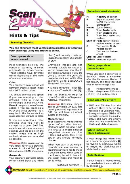
Scanning ChecklistIf your drawing is clean andsharp this is not normally aproblem. However if yourdrawing has faint lines or a dirtyor tinted background you willhave to experiment with yourscanner’s settings until you geta raster image where, as far aspossible, the parts of the rasterimage that are supposed to beblack are black and the partsthat are supposed to be whiteare white.If your scanner or scanningsoftware sets too much of thedrawing to white, it maycontain breaks and holes. Faintparts may be lost.If your scanner or scanningsoftware sets too much of thedrawing to black, textcharacters may “bleed” so thatwhite spaces within them orbetween them become filledand speckles and dirt mayappear in the background.Too muchwhiteOptimalToo muchblackRather than experiment withyour scanner settings until youget optimal levels of black andwhite you may find it easier toscan your drawing in grayscale.You can then use <strong>Scan2CAD</strong>’sThreshold functions to create ablack and white image afterscanning. This will allow you toexperiment with different levelsof black and white withouthaving to rescan the drawing.ResolutionIt is not true that the higherthe scanner resolution, thebetter the vectorization results.For most drawings 200 or 300dpi is adequate.However, if a drawing is small(e.g. a logo) or has fine detail,you may need a higher scannerresolution (see Using <strong>Scan2CAD</strong>to convert logos included withthese <strong>Hints</strong> and <strong>Tips</strong>). On somedrawings you may need a lowerresolution. Ideally, aim forscanned lines that are about 5pixels thick.Scanning physical itemsScanning a physical part like agasket or similar for profilingcan be problematic. Becauseparts have a thickness theyproduce shadows when youscan them. Once in <strong>Scan2CAD</strong>it can be hard to tell where thepart ends and the shadowbegins. Here are two suggestionsto help get around the problem.Suggestion 11.Lay the part on a piece ofwhite paper.2. Carefully trace around it witha fine, sharp pen to get atight fitting profile.3. Scan and vectorize the trace.Suggestion 2To reduce shadowing, put ablack sheet of paper or cardover the part in the scanner.You may also want to try spraypainting the part white. Whenyou scan, the shadows willsimply become part of the blackbackground.This will give you a reversedimage with a white part on ablack background. In <strong>Scan2CAD</strong>,click to switch the image soyou end up with a black parton a white background.Saving raster files... ContinuedIf you’re not scanning directlyinto <strong>Scan2CAD</strong>, save scanneddrawings as BMP or, better, aspackbits, Fax Group 3 or FaxGroup 4 TIFF files. TIFF filesmake more economic use ofhard disk space than BMP files.DO NOT save your files asmulti layer/page TIFF which<strong>Scan2CAD</strong> does not support oras JPEG or GIF, which are coloronly formats.Filling the gray area onthe screen ...When you select an area tozoom into (e.g. the areaenclosed by the red rectanglebelow) ...Only the exact area you havechosen is displayed on thescreen:To expand the displayed areaso it fills the screen, press Ffor Fill:If you press F again, the viewwill zoom out slightly so youcan see more of the imageon the screen.Stuck? Questions? Email us at postmaster@softcover.com. Web: www.softcover.comPage 2© Softcover International Ltd 2002-2006. <strong>Scan2CAD</strong> is a registered trademark of Softcover International Ltd.
How to use <strong>Scan2CAD</strong>This page assumes you are using <strong>Scan2CAD</strong> v7.5 or later and thatyou have not turned off the Warning:Color Image dialog thatappears if you load an image that contains more than two colors.If you have turned the dialog off, reinstall <strong>Scan2CAD</strong> to reactivate it.This page outlines basic steps only. You may prefer to use Andrea’sReal World Guide, which tells you how to handle imperfect scansand tweak vectorization settings. You can get a copy by going towww.softcover.com and clicking the <strong>Hints</strong> and <strong>Tips</strong> button.Convert a black and white imageWithout OCROCR (text recognition) isoptional. Use this method ifyour drawing has no text or thetext is poor quality.1.Click to load a BMP, TIFFetc. raster file, or scan adrawing using File>Acquire.The Warning: Color Imagedialog may appear. If it does:a)Select the second option.b)Click OK. If a warning appears,click Yes. You will enter theSimple Threshold dialog.c) Move the slider to a positionwhere the lines on yourimage are as solid as possibleand the background is asclean as possible.d)Click OK.2.Work through the RasterQuality Checklist suppliedwith these <strong>Hints</strong> and <strong>Tips</strong>.3.Optional (recommended): Click(Raster Effects>Smooth).4.Make sure you are zoomedout by clicking .5.Go to the Type Menu. Thiscontains vectorization settings.• Choose the setting that bestdescribes your drawing, e.g.Architectural or CNC Profile.• If you drawing is a solid shapeto be outlined, choose Outline.6.Vectorize the image byclicking on . Any text willbe converted to short lines.7.Save the vectors as DXF usingFile > Vector > Save As.With OCRUse this method if your drawinghas clear sharp text charactersthat you want to vectorize.Follow Steps 1 to 5 ofWithout OCR. Then:6.<strong>Scan2CAD</strong>’s text recognitionrecognizes raster text when:• The text is easily legible.• Characters do not touch eachother or other drawing elements.• Characters are not atdifferent orientations.• Characters are in a font that<strong>Scan2CAD</strong> can recognize.Work through the RasterText Quality Checklistsupplied with these <strong>Hints</strong> and<strong>Tips</strong> to ensure your textmeets these conditions.7.Tell <strong>Scan2CAD</strong> what text sizeto expect:a)Go to OCR > Char Size.b)Zoom into the biggestcharacter on your drawing byplacing your cursor over itand scrolling your mousewheel forward or pressing theM key several times, until youcan see the character clearly.c) Click on a black part of theraster text character. Itbecomes enclosed in a box.d)Click to zoom out.8.Vectorize ALL the drawing,(drawing elements and text,by clicking on .9.Save the vectors as DXF usingFile > Vector > Save As.After vectorization press V to view Vectors, B to view Bothvectors and raster, Shift+F to Fade the raster, C to toggleviewing vectors by Color or by type and G to toggle Grab Pointdisplay at vector ends. Press Shift+F8 to clear vectors.Create a color DXF filefrom a color raster image1.Click to load a BMP, TIFFetc. raster file, or scan adrawing using File>Acquire.The Warning: Color Imagedialog appears. Select thefourth option and click OK.2.Go to Palette>Reduce ColorsAuto. Select a manageablenumber of colors, e.g. 32.3.Go to Palette > View/EditPalette and group togethersimilar colors:a)Select all shades of a color(e.g. all shades of red) - clickon the shades in the palette(right), in the PreviewWindow (left), or both. (Youmay find this easier if youselect Hue in the dialog.)b)Click .c) Click on one of the colors youselected in (a).d)Click Preview Change. Thecolors you selected in (a) arechanged to the color youselected in (c).e)Repeat (a) to (e) for all colorgroups - whites, blues, etc.f) Click OK.4.Double click your left mousebutton to deselect anyselected colors.You now have two options:Option 1. This option is betterbecause it uses colorinformation while vectorizing.5. Go to Palette > SelectSeparation Colors. Click onthe colors you want tovectorize and click OK.6.Follow Steps 2 onwards ofWithout OCR or With OCR.Option 2. Use this if you wereunable to group the colorscleanly in Steps 2 and 3 above.5.Follow Steps 2 onwards ofWithout OCR or With OCR butjust before you save the DXFfile go to Vector Edit>VectorColors to Raster Colors.Stuck? Questions? Email us at postmaster@softcover.com. Web: www.softcover.comPage 3© Softcover International Ltd 2002-2006. <strong>Scan2CAD</strong> is a registered trademark of Softcover International Ltd.
Not getting the results you were expecting?If <strong>Scan2CAD</strong> isn’t giving you the results you were expecting:1.Work through the Raster Quality Checklist included with these <strong>Hints</strong> and <strong>Tips</strong>.2.Work through the Raster Text Quality Checklist included with these <strong>Hints</strong> and <strong>Tips</strong>.3.Work through the Color Checklist included with these <strong>Hints</strong> and <strong>Tips</strong>.4.Work through the Vectorization Settings Checklist included with these <strong>Hints</strong> and <strong>Tips</strong>.Alternatively, download and use Andrea’s Real World Guide, which tells you how to handle imperfectscans and tweak vectorization settings. If you don’t already have a copy you can get one by going towww.softcover.com and clicking the <strong>Hints</strong> and <strong>Tips</strong> button.Raster Quality ChecklistThe most common reason for poor vectorizationresults is a poor quality raster image. <strong>Scan2CAD</strong>can only give results as good as the raster imageyou give it to vectorize. Nowhere is the saying“Garbage In, Garbage Out” truer than in rasterto vector conversion.Make sure that your image is suitable forvectorization by going through the Raster QualityChecklist below.Do this even if your scanned image looks perfect.Poor quality raster images often look fine whenviewed full screen - it’s not until you zoom intothem that you uncover their real horrors.Is your image negative?(white lines on a black background)Negative imagePositive imageIf your image is slightly skew, deskew it asfollows:• Click (Raster Effects > Rotate > AutoDeskew) to deskew black and white images.• Click (Raster Effects > Rotate > by Line)to deskew any image.Deskewing a very skew image can causesignificant deterioration in image quality. If yourimage is very skew, the best thing to do is torescan your drawing taking care to get thedrawing straight on the scanner.Is your image dirty?If your image is very dirty, you may not be ableto clean it well enough to produce a meaningfulvectorization or cleaning it might take too longto be worthwhile.For example, there is no point trying to clean animage that looks like the one below because thereare solid black dirty areas obscuring the drawing.<strong>Scan2CAD</strong> converts positive images (black orcolored lines on white paper). If your image isnegative you need to click (Raster Effects >Negate) to convert it to positive.Is your image skew?Skew imageAfter deskewHowever if speckles and dirty areas do notinterfere with the drawing itself you will be ableto clean the image quickly and easily.• To despeckle an image, click (RasterEffects > Clean > Remove Speckles).• You can erase dirty areas using <strong>Scan2CAD</strong>’sraster erase tools, particularly the area erase(select) and the freehand erase(select ).• There are often dirty areas around the edgesof raster images. You can delete these usingRaster Effects > Crop.Stuck? Questions? Email us at postmaster@softcover.com. Web: www.softcover.comPage 4© Softcover International Ltd 2002-2006. <strong>Scan2CAD</strong> is a registered trademark of Softcover International Ltd.
Raster Quality ChecklistNow, zoom into your raster image by placingyour cursor over the image and pressing M onyour keyboard. Keep pressing M until the linesare highly magnified. You can also zoom in byscrolling your mouse wheel forwards.What do you see?Hairy linesIf the lines on your imagehave “hairs” like the topline on the right, click(Raster Effects > Smooth)to smooth them (bottomline on the right).Good quality linesThe lines on the left areclean and strong anddistinct. If the lines onyour image look like thisyou will be able to get goodvectorization results.Dithered linesIf the lines on your imageare dithered (made up ofblack speckles like thelines on the left), the bestthing to do is to rescanyour drawing. Experimentwith your scanner’ssettings until you get a scan with solid, continuouslines that are not dithered (see the ScanningChecklist included with these <strong>Hints</strong> and <strong>Tips</strong>).If rescanning is not an option, try using(Raster Effects > Thicken > Pixels).You may need to run Thicken > Pixels severaltimes to improve the quality of a dithered imageto the point where it can be vectorizedsuccessfully. However, use Thicken > Pixels withcare as it can deteriorate the quality of the imageby thickening lines too much and allowing linesthat are close to each other to become joined.Lines with holesIf the lines on your imagecontain small holes youcan remove them using(Raster Effects >Clean > Remove Holes).To remove large holes use<strong>Scan2CAD</strong>’s Flood Fill command (see the Help).... continuedIf your image has holes it may have been scannedat too high a resolution. You may want to tryscanning your drawing again at a lower resolution.Broken linesIf the lines on your imageare slightly broken you canprobably mend themautomatically using one ofor a combination of thefollowing methods:• (Raster Effects > Thicken > Lines).• (Raster Effects > Thicken > Pixels).• Gap jumping. Before you vectorize the image:1.Select a Type from the Type Menu.2.Go to Type > Settings.3. Set a Gap Jump Distance.When you vectorize the image <strong>Scan2CAD</strong> willjump over breaks that are smaller than thedistance you have specified, allowing it toproduce continuous vectors despite the gaps.If the lines on your image are very broken youwill not be able to mend them automatically orjump over the gaps using gap jumping. The onlyway to mend a very broken image is to draw newraster lines and arcs over the broken ones.If your entire image is very broken it will taketoo long to improve its quality to the point whereit can be successfully vectorized and there isprobably no point trying to vectorize it.Merged linesIf the entities on yourraster image are mergedtogether the raster imageis too poor quality forvectorization. There isnothing you can do aboutthis unless the original drawing shows white spacebetween the entities. In this case it may bepossible to separate the entities by scanning thedrawing again at a higher resolution.Fuzzy linesIf the lines on your rasterimage are fuzzy the rasterimage is too poor qualityfor vectorization. There isnothing you can do aboutthis except rescan thedrawing using the Scanning Checklist includedwith these <strong>Hints</strong> and <strong>Tips</strong>.Stuck? Questions? Email us at postmaster@softcover.com. Web: www.softcover.comPage 5© Softcover International Ltd 2002-2006. <strong>Scan2CAD</strong> is a registered trademark of Softcover International Ltd.
Raster Quality ChecklistFuzziness is most common in JPEG images, sotake care not to save your image in JPEG format.Overlaid informationThe drawing on the rightcontains a lot of overlaiddata.Sadly, <strong>Scan2CAD</strong> is nothuman. It doesn’t knowthat it is looking at textand a wiring scheduleoverlaid on a building plan.All it sees are blackpatterns on a white background and it is not goingto be able to separate the data.You are not going to be able to get a sensible... continuedvectorization from an image with overlaidinformation. There is nothing you can do aboutthis.Low resolution linesIf shapes in your image aredefined by only a fewpixels and look jagged, asin the image on the right,your image is too lowresolution. This is particularlycommon in logos anddrawings with fine detail.The drawing needs to berescanned at a muchhigher resolution - aim for lines that are about 5pixels thick.Raster Text Quality Checklist<strong>Scan2CAD</strong> has a capability for converting raster text to vector textusing OCR. When you convert raster text using OCR, the vectortext is proper editable text rather than a series of uneditable linesand arcs.<strong>Scan2CAD</strong>’s OCR recognizes raster text where the followingconditions are met:• The raster text is easily legible.• The raster text characters do not touch each other.• The raster text characters do not touch other drawing elements.• The raster text characters are not at different orientations.• The raster text characters are in a font that <strong>Scan2CAD</strong> canrecognize.To ensure that your text meets these conditions, work through thefollowing Raster Text Quality Checklist.First, place your cursor over a piece of text on your image.Press M to Magnify. Press M again and again until your image ishighly magnified. Or, zoom in by scrolling your mouse wheelforward. To zoom out again, click .Is the text easily legible?If you cannot read the texteasily, as in the examplesbelow, <strong>Scan2CAD</strong> won’t be ableto read it either.If the text is not easily legible,the only remedy is to start offwith a better quality rasterimage.If this is not possible, you willhave to retype the textmanually. You can either do thisin <strong>Scan2CAD</strong> (see Typing overpoor quality text included withthese <strong>Hints</strong> and <strong>Tips</strong>) or in yourCAD program after you haveimported the converted file intoit.You may want to erase areas ofvery poor quality text from theraster image so that these areasare not vectorized to lines andarcs.Are the characterstouching?<strong>Scan2CAD</strong> cannot recognizecharacters that touch othercharacters, even if thecharacters are only connectedby a few pixels:If the characters touch, tryselecting OCR > Settings >Split before doing OCRrecognition. When this option isselected <strong>Scan2CAD</strong> will attemptto split and identify touchingcharacters.This will improve textrecognition on some rasterimages, however on others itmay result in a lot of “junkcharacters” being recognized.This is because characters thattouch are often very poorquality and are unrecognizableeven after splitting. Forexample, the characters in theexample above have “bled”. Notonly has this caused them totouch each other but it has alsofilled in the “A”. This means thatthe “A” is no longer typical ofStuck? Questions? Email us at postmaster@softcover.com. Web: www.softcover.comPage 6© Softcover International Ltd 2002-2006. <strong>Scan2CAD</strong> is a registered trademark of Softcover International Ltd.
Raster Text Quality Checklist... continuedan “A” and <strong>Scan2CAD</strong> may havedifficulty recognizing it even ifit is not touching othercharacters.You can often improve thequality of an image that hasbled by rescanning it ingrayscale and thresholding it(see the Scanning Checklistincluded with these <strong>Hints</strong> and<strong>Tips</strong>).Is the text written overother drawing elements?If text is written over drawingelements or is attached tounderlining or boxes as in theexamples below, <strong>Scan2CAD</strong>won’t be able to recognize it.Is the text at more thanone orientation?<strong>Scan2CAD</strong> can only reliablyrecognize text at oneorientation at a time.Where text at differentorientations is physicallyseparate it can be recognizedusing separate OCR runs.However, where text at oneorientation is intermingled withtext at another orientation it isvirtually impossible to recognizeall the text. This typically affectsdrawings with dimension text atdifferent angles, contour mapsand site plan drawings such asthe one below.Can <strong>Scan2CAD</strong> recognizethe font?By default, <strong>Scan2CAD</strong> can onlyrecognize text that has beenwritten using a standard fontsuch as the font below.It may not recognize other fontswell. It may also fail torecognize standard fonts thatare narrower or wider thannormal or that are italicized.If <strong>Scan2CAD</strong>’s default textrecognition cannot recognize afont well and you have a lot ofimages containing that font,you can train <strong>Scan2CAD</strong> torecognize the font (Pro versiononly). You can do this if the fontcharacters are consistent anddo not touch.For example:<strong>Scan2CAD</strong>’s default textrecognition will recognize thisfont but it will not recognize itoptimally because the font isnarrower than normal. Youcould train <strong>Scan2CAD</strong> torecognize this font well.Viewing vector elementsViewing Grab Points at vectorends is a quick way to seevector extents.Press G to turn Grab PointsOn/Off.To change Grab Point size goto View > Grab Point Size.You can see different vectortypes in different colors:Press C to turn vector ColorsOn/Off.<strong>Scan2CAD</strong>’s default textrecognition will recognize thisfont very poorly because it isitalicized and hand written.However, because thecharacters are clear and do nottouch you could train <strong>Scan2CAD</strong>to recognize it.<strong>Scan2CAD</strong>’s default textrecognition will recognize thisfont very poorly because it ishand written and because thecharacters touch each other.You could not train <strong>Scan2CAD</strong>to recognize this font becausethe characters touch.Despite the fact that the qualityof this text is poor you couldtrain <strong>Scan2CAD</strong> to recognize itbecause the characters areconsistent and do not toucheach other.It takes a few hours to train<strong>Scan2CAD</strong> to recognize a fontbut it can significantly improvetext recognition.Vector types are shown in thefollowing colors:Continuous linesDash linesArrow linesHatch linesPolylinesCirclesArcsBezier curvesTextRedBlackGrayBrownGreenDark blueMagentaPale blueMagentaStuck? Questions? Email us at postmaster@softcover.com. Web: www.softcover.comPage 7© Softcover International Ltd 2002-2006. <strong>Scan2CAD</strong> is a registered trademark of Softcover International Ltd.
Color ChecklistLook at the number after the file name at the top of the screen. Ifthis number is 256 or 16.7M your image is grayscale or color,even if it looks black and white!If you try to vectorize a grayscale or color image there are threelikely outcomes:The vectors look like crazy paving OR there are no vectors at allOR there are a few horizontal and vertical lines at the image edge.Solutions• Use Thresholding to reduce image colors to black and white:1.Click to do a Simple Threshold or to do an AdaptiveThreshold. If a Threshold Information dialog appears, click Yesto continue.2.Move the slider(s) to a position where the lines on your imageare as solid as possible and the background is as clean as possible.Click the Help button in the Simple or Adaptive Threshold dialogfor more information on how to use the sliders.• Whiten the image background:1.Go to Palette > View/Edit Palette.2.Click on the colors that look white so they become selected.(To select a row of colors, click at the right hand end of the row.)3.Click on Change To White.4.Click on OK.• Rescan the drawing using the Scanning Checklist included withthese <strong>Hints</strong> and <strong>Tips</strong>.Vectorization Settings ChecklistA technical explanationBy default, <strong>Scan2CAD</strong>vectorizes every non-whitepixel it sees on a whitebackground. It does notvectorize white pixels.Sometimes a backgroundthat looks white is slightlynon-white. Maybe it's crisscrossedby non-white areasleading to crazy pavingvectors, or maybe it'scompletely non-white leadingto no vectors.In a 256 color image 255 ofthe colors are non-white.Now imagine an image with16.7 million colors whereonly one is white! You cansee how easy it is to end upwith a non-white background!The problem is particularlylikely if you are convertingJPEG files because JPEGs canonly be color.Vectorization settings control the conversion ofraster images to vectors.The default settings thatare set when you select an option from the TypeMenu give good results on most drawings butsometimes you may need to edit them.If dash lines are not recognizedMake sure that Type > Settings > ObjectIdentification > Dash Line is selected.Dash Linenot selectedDash LineselectedIn the diagrams above vector end points areenclosed in small squares.If Dash Line is selected and dash and dash dotlines are still not being identified try increasingthe maximum dash and gap lengths in Type >Settings > Advanced.If arrows are not recognizedMake sure that Type > Settings > ObjectIdentification > Arrow Line is selected.If arrows are still not identified try increasing themaximum arrow head length in Type > Settings> Advanced.Arrows will not be recognized when the arrow tipis touching a line that has a similar width to thearrow head. If an arrow is recognized as a line,you can quickly change it to an arrow as follows:1.Click .2.Right click.3.Select Arrow 1 or Arrow 2 from the dialog.4. Click on the lines you want to convert to arrows.The arrow head will be at the end of the lineyou click on.If polylines are not recognizedMake sure that Type > Settings > ObjectIdentification > Polyline is selected. Alternatively,use Vector Edit > Make Polylines to createpolylines after vectorization.Stuck? Questions? Email us at postmaster@softcover.com. Web: www.softcover.comPage 8© Softcover International Ltd 2002-2006. <strong>Scan2CAD</strong> is a registered trademark of Softcover International Ltd.
Vectorization Settings ChecklistIf hatch lines are not recognizedMake sure that the Hatch option correspondingto the angle of the hatch lines you want to identifyis selected in Type > Settings > ObjectIdentification.If hatch lines are still not identified, try increasingthe Hatch Line angle tolerance in Type > Settings> Advanced.If hatch lines are identified but the lines are notparallel, select the angle in Type > Settings >Angle Optimization that corresponds to the angleof the hatch lines you want to identify.If arcs or Bezier curves are not recognizedIf arcs are not recognized make sure that Type >Settings > Object Identification > Arc is selected.If Bezier curves are not recognized make surethat Type > Settings > Object Identification >Bezier is selected.You can choose to identify arcs or Bezier curves.If the image is a typical architectural, mechanicalor electrical drawing containing mainly straightlines, select arc. If the image is mainly curvy,like a contour map, ship hull, aerofoil or freeformartwork select Bezier. If you are vectorizing acurvy image but your CAD or CNC program doesnot support splines you can still select Bezier.You can convert the Bezier curves to arcs or lineson export using File > Vector > Export Options.If circles are not recognizedIf circles are not recognized make sure that Type> Settings > Object Identification > Circle isselected.Line WidthIf thick lines contain double vectors, increase Type> Settings > General > Line Width.Double vectorsAfter increasingLine Width... continuedDeviation FactorIf the vectors do not follow the lines on the rasterimage closely enough, decrease Type > Settings> General > Deviation Factor.Loose vectorsAfter decreasingDeviation FactorIf you have to decrease the Deviation Factor youmay have scanned your drawing at too low aresolution. You may want to try rescanning it ata higher resolution.Corner SnapIf corners are chamfered, increase Type >Settings > General > Corner Snap to sharpenthem. You may also need to increase Type >Settings > Advanced > Corner Snap AngleTolerance.Chamfered cornerAfter increasingCorner SnapPass-Thro SnapIf vectors do not cross neatly at untidy rasterjunctions, increase Type > Settings > General >Pass-Thro Snap.Untidy junctionAfter increasingPass-Thro SnapLoose Ends LengthIf you have a lot of loose end vectors, increaseType > Settings > General > Loose Ends Length.If you have to increase Line Width, the lines onyour raster image are thicker than normal. Thickerlines have more unwanted protrusions and holesso use Raster Effects > Smooth ( ) and RasterEffects > Clean > Remove Holes ( ) beforevectorization. You may want to try rescanningyour drawing at a lower resolution to decreasethe line thickness.Loose end vectorsAfter increasingLoose Ends LengthTo avoid loose end vectors, use Raster Effects >Smooth ( ) before vectorization.Stuck? Questions? Email us at postmaster@softcover.com. Web: www.softcover.comPage 9© Softcover International Ltd 2002-2006. <strong>Scan2CAD</strong> is a registered trademark of Softcover International Ltd.
Vectorization Settings ChecklistGap Jump DistanceIf the vectors are broken at breaks in the rasterimage, increase Type > Settings > General > GapJump Distance.Broken vectorsAfter increasing Gap JumpDistance... continuedAngle OptimizationIf the vectors deviate slightly from their correctangles due to variations in the raster imagebeneath, select angles in Type > Settings > AngleOptimization. For example:Angle Optimization Angle Optimization90/180 = off 90/180 = onIf there are a lot of breaks in your raster imageyou may be able to jump them more effectivelyif you use Raster Effects > Thicken > Lines ( )and Raster Effects > Thicken > Pixels ( ) beforevectorization.Connect Thro NodesIf you want lines to pass at intersections ratherthan join, select Type > Settings > General >Connect Thro Nodes.Lines join atintersectionsLines pass atintersectionsIn the diagrams above line end points areenclosed in small squares.Arcs, Bezier curves and Circles always continuethrough intersections even if Connect Thro Nodesis off.Align to current gridIf you want to snap vectors to a grid, select agrid spacing using Vector Edit > Grid SnapDistance.To view the grid, press Shift+I or select View >View Grid. Note that you will only be able to seethe grid when you are zoomed in.Select Type > Settings > General > Align toCurrent Grid.In the diagrams below the raster image and gridlines are shown in gray and the vectors aresuperimposed in black.Vectors notVectors snappedsnapped to a grid to a gridWhen 90/180 is on, lines within a user-specifiedtolerance of 90 or 180 degrees are snapped to90 or 180 degrees.Angle Optimization Angle Optimization45 = off 45 = onWhen 45 is on, lines within a user-specifiedtolerance of 45 degrees are snapped to 45degrees.If Angle Optimization does not appear to beworking, this is because <strong>Scan2CAD</strong> has chosennot to optimize a line or lines. It may do this ifoptimizing the line(s) would interfere with thelogical position of a node.If Angle Optimization is set on an image that doesnot have lines at the angles that have beenselected for Angle Optimization, gross distortionof vectors can result:In this case, turn Angle Optimization off.You may also want to see Andrea’s RealWorld Guide, which tells you how to improvevectorizations by tweaking vectorizationsettings. If you don’t already have a copy, youcan get one by going to www.softcover.comand clicking the <strong>Hints</strong> and <strong>Tips</strong> button.In the diagrams in this Checklist the rasterimage is shown in gray and the vectors aresuperimposed in black.Stuck? Questions? Email us at postmaster@softcover.com. Web: www.softcover.comPage 10© Softcover International Ltd 2002-2006. <strong>Scan2CAD</strong> is a registered trademark of Softcover International Ltd.
Using <strong>Scan2CAD</strong> to convert PDF files to DXFYou can use <strong>Scan2CAD</strong> to convert a PDF file toDXF by first converting the PDF file to a rasterformat such as TIFF or BMP. Once it’s in rasterformat, you can load it into <strong>Scan2CAD</strong> and convertit to DXF in the normal way.There are a number of programs available thatcan convert PDF files to raster. Two - Photoshopand Omniformat - are described here. Omniformatis free but displays sponsor pages.Using PhotoshopThe instructions below have been written forPhotoshop CS but may also work with otherversions of Photoshop.1.Load your PDF file into Photoshop by going toPhotoshop’s File Menu and choosing Open.Depending on the properties of the PDF file, itwill either open straight up in Photoshop or theRasterize Generic PDF Format dialog will appear.If the Rasterize Generic PDF Format dialogappears:• Leave the Width and Height figures atPhotoshop’s defaults.• Set Resolution. 300 pixels/inch is good formost line drawings, but on small drawings likelogos you may need to try a higher resolution.• Set Mode to Grayscale.• Switch off the Anti Aliased option.• Click OK. The PDF file will appear in Photoshop.• Zoom into the file and inspect it. If it is broken,or you can’t read the text as in the examplesbelow, the resolution is too low. <strong>Scan2CAD</strong> willnot be able to vectorize the image well. In thiscase, close the image and load it into Photoshopagain, this time choosing a higher resolution.2.Go to Photoshop’s Image Menu > Mode. IfBitmap is not ticked, click on it. Then:a)Click OK to the Flatten Layers prompt.b)A dialog called Bitmap appears.c) Leave the Output Resolution at default.d)Set the Method to 50% Threshold.e)Click OK. This converts the image black andwhite (2 colors).3.Save the file in TIFF format. In the TIFF Optionsdialog set Image Compression to None.4.Load the TIFF file into <strong>Scan2CAD</strong> by starting<strong>Scan2CAD</strong> and clicking . You can nowvectorize the file in the same way as any otherraster image.Using OmiformatDownloading and installing Omniformat1.Go to http://www.omniformat.com/download.html2.Click on the Omniformat Download link anddownload Omniformat (omniformat.exe) toyour hard drive.3.In order to use Omniformat you will also haveto download its sister product PDF995 and thePDF995 printer drivers.To do this, click on the PDF995 Download link.This will take you to another web page.Download the PDF995 Printer Driver(pdf995s.exe) and the Free Converter(ps2pdf995.exe) to your hard drive.4.You should now have three files on your harddrive - omniformat.exe, pdf995s.exe andps2pdf995.exe.Install them in the following order:ps2pdf995.exe, pdf995s.exe, omniformat.exe.Using OmniformatOnce you’ve installed Omniformat you are readyto turn a PDF file into a raster image suitable for<strong>Scan2CAD</strong> to convert. Do the following:1.Load the PDF file you want to convert intoAcrobat Reader. Make a note of the file’s papersize - it’s width and height will be displayed atthe bottom left of the Acrobat screen (you mayneed to pass your mouse over the bottom leftof the screen to see the width and height).2.Go to Start > All Programs > <strong>Software</strong>995> Omniformat. Sponsor page messages andsponsor pages will appear. Once you havepassed these, the Omniformat dialog appears.3.Select BMP Microsoft Windows bitmapimage from the Output Format dropdown.4. Click the Options button. The Options dialogappears.a)Select an appropriate resolution value (see Anote about resolution overpage).Stuck? Questions? Email us at postmaster@softcover.com. Web: www.softcover.comPage 11© Softcover International Ltd 2002-2006. <strong>Scan2CAD</strong> is a registered trademark of Softcover International Ltd.
Using <strong>Scan2CAD</strong> to convert PDF files to DXFIf your PDF file is smaller than A0/E size (i.e.smaller than 48x36 inches or 841x1189 mm)we suggest you start by trying a resolution of300. If your PDF file is larger than A0/E wesuggest you start by trying a resolution of 72.b)Click OK to exit the Options dialog.5.Click the Start Monitoring button.6.Use Windows Explorer to copy a PDF file intothe Watch Folder specified in the Omniformatdialog. By default the Watch Folder is atc:\program files\omniformat\watch.VERY IMPORTANT: Omniformat will deletethe PDF file from the Watch Folder once it hasconverted it so it is important that you COPYthe PDF file you want to convert into the WatchFolder. DO NOT put the original there.... continuedYou can now vectorize the BMP file in the sameway as any other raster image.A note about resolutionOmniformat allows you to select a raster fileresolution. The correct resolution will depend onyour drawing. You may have to experiment withdifferent resolutions to find the best one.When you have loaded the BMP file thatOmniformat has created into <strong>Scan2CAD</strong>, zoominto it and take a look. If it is broken, or youcan’t read the text as in the examples below, theresolution is too low and <strong>Scan2CAD</strong> will not beable to vectorize the image well. In this case,use Omniformat to create the BMP file again, thistime using a higher resolution.Omniformat will automatically convert the PDFfile to BMP.(Note: You can convert several PDF files to BMPat once by copying more than one PDF file intothe Watch Folder.)7.Load the BMP file into <strong>Scan2CAD</strong> by starting<strong>Scan2CAD</strong> and clicking .Omniformat creates 256 color BMP files, so theWarning: Color Image dialog may appear. If itdoes, select the second or third option and clickOK. If the Warning: Color Image dialog doesnot appear and your BMP file only contains blackand white colors you can reduce the size of thefile by decreasing its color depth. To do this,go to <strong>Scan2CAD</strong>’s Palette Menu and chooseReduce Color Depth > 1 Bit [Mono].A word of warning: You should be able toconvert any file up to A0/E paper size (48x36inches or 841x1189mm) using Omniformat’smaximum resolution of 300 dpi. If the paper sizeof your PDF file is larger than this, use a lowerresolution. Attempting to create a BMP file froma large PDF file can make a file many hundredsof Mb in size that can choke your PC. You can tellthe paper size of your PDF file by loading it intoAcrobat Reader. The file’s width and height areshown at the bottom left of the Acrobat screen(you may need to pass your mouse over thebottom left of the screen to see them).How to scroll through an image screen by screenScrolling through an image one screen at a timeallows you to go through the whole image withoutmissing any of it. This is really useful when you’recleaning a raster image, tidying a vector imageor just checking results.1.Zoom into the image so you can see enoughdetail to be able to clean the image or dowhatever you need to do.When you zoom in, the right hand part of thescreen may be gray. Press F on your keyboardto Fill the gray part of the screen with image.2. Use the scroll bars to move to the top left cornerof the image.3.Press the Ctrl+Right Arrow keys to move onescreen to the right.4.Repeat Step 3 until you have moved, screenby screen, all the way across the image.5. Now press the Ctrl+Down Arrow keys to moveone screen down.6. Use the Ctrl+Left Arrow keys to move onescreen to the left.7.Keep moving to the left until you have movedall the way across the image, then move down,then right, then down, then left, then down,etc., until you have moved through the entiredrawing.Stuck? Questions? Email us at postmaster@softcover.com. Web: www.softcover.comPage 12© Softcover International Ltd 2002-2006. <strong>Scan2CAD</strong> is a registered trademark of Softcover International Ltd.
Using <strong>Scan2CAD</strong> to convert logosSometimes people contact us to say they’re having difficultiesconverting a logo. When they email us their problem logo we usuallyfind that the root of the problem is one of the following:• The logo is a GIF or JPEG file designed for web use• The logo has been scanned at too low a resolutionThese problems are detailed here, along with the best way to get alogo scan that will give you a good conversion.The logo is a GIF or JPEGfile designed for web useThe JPEG file below, “Jane’sFlowers”, looks fine on the web,because that’s what it’s beendesigned for - web display.However, if you load it into<strong>Scan2CAD</strong>, Photoshop or anysimilar program and zoom intothe “r” in the word “Flowers”this is what you’ll see:Looked at close up, the “r” isnot discernable even to thehuman eye. It’s not surprisingthat <strong>Scan2CAD</strong> has difficultieswith this type of logo.An image with an intended enduse of web display requirescompletely different attributesfrom an image with an intendedend use of vectorization.Images downloaded from theweb are generally unsuitable forraster to vector conversion.The logo has been scannedat too low a resolutionLogo artwork tends to be smalland this means that we oftensee logos that have beenscanned at too low a resolution.While we recommend 200 or300 dpi as an optimal scanningresolution for most drawings, itis too low if the drawing you’rescanning is a small logo.To illustrate the problems you’relikely to encounter whenscanning a small logo we drewthe “Jane’s Flowers” logo so thatit measured approximately 1.6"x 1" (4cm x 2.5cm) in size.Below is the “r” in the word“Flowers” after scanning thelogo at 300 dpi. You can see thatthe outline of the “r” is veryjagged. This means that it is toolow resolution.You will not be able to producea good vectorization from thisimage:After scanning at 1200 dpi(below) the logo outline is muchsmoother, but scanning at ahigher resolution has resultedin a new problem.At the higher resolution thescanner has picked out tinydetails that are not visible to thehuman eye when viewing thelogo on paper. Because theartwork is so small, thesedetails are large in relation tothe size of the logo. This meansthat the corners of the “r” havebecome rounded and the linesof the “r” are bumpy instead ofstraight and smooth.You will be able to produce ausable vectorization from thisimage, but the vectorizationwon’t be as good as it could be(see Getting the bestpossible scan for logovectorization overpage).Note that the rounded cornersof the scanned “r” have beenreflected in the vectorization bychamfers (see overpage).Stuck? Questions? Email us at postmaster@softcover.com. Web: www.softcover.comPage 13© Softcover International Ltd 2002-2006. <strong>Scan2CAD</strong> is a registered trademark of Softcover International Ltd.
Using <strong>Scan2CAD</strong> to convert logos... continuedTo sharpen the corners, do thevectorization again, but beforeyou do it go to the Type Menu,select Settings and enter aCorner Snap. <strong>Scan2CAD</strong> willthen remove all chamfersshorter than the Corner Snapand join the main lines together,giving sharp corners:To conclude, you will never beable to get a really good scanfrom small original artwork. Thiswill be reflected in the resultsyou can expect.Getting the best possiblescan for logo vectorizationTo get the best possible scan forlogo vectorization, start with abigger logo.We drew the “Jane’s Flowers”logo again, but this time wedrew it bigger so that it filled aletter size / A4 sheet.Here is the “r” in “Flowers” afterscanning the bigger logo at 300dpi. The scanned outline issmooth and clean:Note that to get a good scan likethis your original artwork mustbe large. You cannot start withsmall original artwork andenlarge it on a photocopier. Thiswill result in a scan that is nobetter - and that is probablyworse - than the scan you wouldget if you scanned small artworkat a high resolution.Once you have a smooth cleanscan you can vectorize it asfollows.1. Go to Type > Outline.2. Click to vectorize the logo.This will produce a vector imagemade up of lines and Beziercurves:If your CAD/CNC programdoesn’t support Bezier curvesyou can convert them topolylines or arcs on export.Alternatively, you can vectorizethe scan as follows:1. Go to Type > Outline.2. Go to Type > Settings.3. Click the Object IdentificationTab, select Arc and click OK.4. Click to vectorize the logo.This will produce a vector imagemade up of lines and arcs.If you can’t see any vectorsafter you’ve done thevectorization, press C on yourkeyboard to display the vectorsin different colors.If you still can’t see any vectors,or if your vectors looksomething like this ...... it’s likely that your image isgrayscale or color, even if itlooks black and white. Do thefollowing:1. Press Ctrl+F8 to delete allvectors.2.Go to Palette > ReduceColors Auto > 2. This willturn your image into blackand white. Turning agrayscale or color image intoblack and white often givesit ragged edges and leaveswhite holes in the blackareas, so ...3. Click (Raster Effects >Smooth) to smooth theragged edges.4. Click (Raster Effects >Clean > Remove Holes) tofill the holes.Now repeat the vectorization.And finally ...Once you’ve scanned your logo,don’t save it as JPEG as this willalmost certainly reduce thequality of your scan. Save it asTIFF or BMP.Stuck? Questions? Email us at postmaster@softcover.com. Web: www.softcover.comPage 14© Softcover International Ltd 2002-2006. <strong>Scan2CAD</strong> is a registered trademark of Softcover International Ltd.
How to quickly edit DXF from poor quality scansIf you’ve vectorized a poor quality scan and ended up with a messy DXF file you can still useit to quickly build up a drawing in CAD. <strong>Scan2CAD</strong> user Alan Darbyshire describes how.“I use <strong>Scan2CAD</strong> on everycontract drafting job I do. As Iam supposed to be redrafting adrawing from scratch mycustomers expect 100% firstquality but to save myself timeI use <strong>Scan2CAD</strong> to do 80% ofthe work and I do the rest, thusensuring that the final resultsare perfect.“The problem is that 99% of thedrawings I get are copies, notoriginals. When I scan thesepoor quality copies and convertthem in <strong>Scan2CAD</strong> the resultsare not as good as if I wasworking from the originalmaster drawing. Fortunately,I’ve developed a way aroundthis problem which has provedvery useful when I’m redrawinga very messy DXF file.“Once <strong>Scan2CAD</strong> has createdthe DXF file I import this intothe CAD software. In my case,it’s AutoCAD. The method I useis as follows. I place the<strong>Scan2CAD</strong> DXF geometry ontoTyping over poor quality texta faint colored layer that I call‘S2C’, dark gray if it’s on a blackbackground. Then I createanother layer, which I call ‘Trace’and make this white. Next, Ichange all of the perfectgeometry from the ‘S2C’ layeronto ‘Trace’. The easiest way todo this is to just select the ‘S2C’entities, then pick the ‘Trace’layer. This is a standard methodof moving geometry form onelayer to another in AutoCAD.“Very quickly I am able to buildup the detail required. Note thatI am not drawing over the ‘S2C’layer, simply changing it to the‘Trace’ layer. I use AutoCAD’sOffset and Fillet Zerocommands to tidy up andmodify the <strong>Scan2CAD</strong> DXF file,plus I am able to ‘snap’ to the<strong>Scan2CAD</strong> geometry to add ortidy any items as required. Idon’t have to start from a cleansheet in CAD. It is surprisinghow quickly I can build up thedetail. Afterwards, I just deletethe leftover entities on the ‘S2C’layer using AutoCAD’sProperties ‘Funnel’ to search forall the ‘S2C’ entities.“This method allows me tocomplete the drawing in aroundhalf the time it takes to redrawit from scratch. The result is anaccurate drawing I can email tomy customer who can carry outhis amendments in turn.“When the master drawing isgood and I scan it correctly, Ihave a lot less work to doafterwards. If you have anarchitectural drawing it is ofparamount importance that youscan it in straight as this willaffect the results you get. Yes,you can rotate a skew drawingin <strong>Scan2CAD</strong> but if you scan itstraight in the first place it willsave you an additional step inthe tidying-up process later on.“<strong>Scan2CAD</strong> has saved me a lotof time and given me a rapidpayback on my investment. Itreally does help me get my workdone more quickly!”When the text on your raster image is simply too poor quality to convert to vector text using<strong>Scan2CAD</strong>’s OCR, the easiest way to convert it is to type new vector text over it.To do this, we suggest you vectorize the drawingin the normal way. Then, for each piece of text,erase the unwanted vectors that have beenrecognized over it and type the new vector text.Once you’ve typed the new text, you may needto edit it, change its size or move it. Finally,you may want to erase the raster text beneath.Erasing unwanted vectorsSuppose you’ve vectorized a drawing that containspoor quality raster text:Before you can type new, clean vector text overthe raster text, you need to delete the unwantedvectors. To do this:1. Ensure the Vector Edit, Erase and Area Iconsare selected:If they’re not, select them by clicking on them.2.Drag a box around the area of vectors you wantto erase:The text will vectorize to lots of short vectors:Stuck? Questions? Email us at postmaster@softcover.com. Web: www.softcover.comPage 15© Softcover International Ltd 2002-2006. <strong>Scan2CAD</strong> is a registered trademark of Softcover International Ltd.
Typing over poor quality textIt doesn’t matter that the raster text is alsoenclosed within the box. As you are in VectorEdit mode, only the vectors will be deleted.Typing new vector text1. Ensure the Vector Edit, Draw and Text Iconsare selected:If they’re not, select them by clicking on them.2.Click at the bottom left of the raster text youwant to write over:Moving vector text... continued1. Ensure the Vector Edit and Move Grab PointIcons are selected:If they’re not, select them by clicking on them.2.If grab points are off, press G on your keyboardto turn them on. Pressing G toggles grab pointson and off. If you need to make the grab pointsbigger so you can see them better go to theView Menu and choose Grab Point Size.Grab points OFF:The Vector Text Edit dialog appears. If it appearspartially over the raster text you want to writeover, drag it out of the way.3.Type the text into the dialog.4.Press [Enter] or click OK to exit the dialog.The vector text you have typed appears overthe raster text:Editing vector text1. Ensure the Vector Edit, Draw and Text Iconsare selected:If they’re not, select them by clicking on them.2.Click on the text you want to edit. The VectorText Edit dialog appears.3.Edit the text in the dialog.4.Press [Enter] or click OK to exit the dialog.Grab points ON:The text’s grab point is the gray box at thebottom left.3.Position the cursor over the text’s grab pointand drag the text to its new position.If the text doesn’t move, try increasing the GrabSnap Distance. You can do this by pressing thePeriod key on your keyboard (also marked >)or by using Vector Edit > Grab Snap Distance.Erasing the raster text beneath1. Ensure the Raster Edit, Erase and Area Iconsare selected:If they’re not, select them by clicking on them.2.Drag a box around the raster text you want toerase:Changing vector text size1. Ensure the Vector Edit, Draw and Text Iconsare selected:If they’re not, select them by clicking on them.2.Click on the text you want to change the sizeof. The Vector Text Edit dialog appears.3. Edit the Height value in the dialog.4.Press [Enter] or click OK to exit the dialog.It doesn’t matter if your newly-typed vectortext is also enclosed within the box. As you arein Raster Edit mode, only the raster text willbe deleted although initially it will look asthough the vector text has been deleted as well.3.Press B on your keyboard or click on the ViewBoth Icon to re-display the vector text:Stuck? Questions? Email us at postmaster@softcover.com. Web: www.softcover.comPage 16© Softcover International Ltd 2002-2006. <strong>Scan2CAD</strong> is a registered trademark of Softcover International Ltd.
How to edit raster text on a scanned drawingWe’ve been in contact with a lot of users who areusing <strong>Scan2CAD</strong> as a raster editor and who areusing it to re-type and edit raster text.Rather than using <strong>Scan2CAD</strong>’s raster text writingtool to do this, we suggest the following.1. Write your new or edited text using <strong>Scan2CAD</strong>’sVECTOR text writing tool.Writing text as vector instead of as raster givesyou the advantage of being able to easilychange the size of the text, correct any errorsyou make and move the text around after youhave written it. For information on writing,editing and moving vector text, see Typingover poor quality text included with these<strong>Hints</strong> and <strong>Tips</strong>.2.After you have written all your vector text (anddeleted any raster text beneath):a)Click to make sure you are fully zoomedout.b)Press C to turn the vector text black, if it isdisplayed in magenta.c) Go to File Menu > Vector > Rasterize.This will convert the vector text to raster.You can also rasterize individual bits of vectortext by windowing them or zooming into them,then choosing File Menu > Vector > Rasterize.Use <strong>Scan2CAD</strong> to load raster images into AutoCAD LT!Because AutoCAD LT’s image insert command isdisabled, you can’t load raster images into itdirectly.<strong>Scan2CAD</strong>’s Attach Raster Image option gives youa way to load raster images into LT. See the<strong>Scan2CAD</strong> Help for more information on theAttach Raster Image option.If you have <strong>Scan2CAD</strong> and AutoCAD LT, this opensup a whole range of possibilities. For exampleyou can:• View and edit the vectors in LT with the rasterunderneath in a different color (Raster Overlay).• Vectorize only the parts of a drawing you needto change - and leave the parts you don’t needto change in raster format.• Load just the raster image into LT without anyvectors - and trace or draw over it in CAD.To load the raster image into LT without vectors:1.Load the raster image into <strong>Scan2CAD</strong>.2.Select the Attach Raster Image option asfollows:a)Go to File Menu > Vector > Export Options.b)Select the Attach Raster Image option.c) Select a raster color by entering a number intothe CAD Color Index box. Good colors tochoose for LT are:2 (yellow)8 (dark gray)9 (light gray)d)Click OK.3.Create a blank DXF file by clicking .4.Save the DXF file.5.Open the DXF file in AutoCAD LT.Outlining an object on a photoUsers sometimes send us color or grayscalephotos of objects they’d like to vectorize theoutline of. We’ve seen cows, cats, cars ...Unfortunately, vectorizing an object on a photocan be very difficult. This is because before youcan vectorize the object you need to divide thephoto into two discrete color areas: The objectand the background. This is usually hard to doautomatically because the object and thebackground tend to share colors or shades of graythat make it difficult or impossible to separate them.Here’s a quick “cheat” approach:1. Get a piece of tracing paper and trace aroundthe object on the photo with a pen or pencil.2. Scan the traced outline.3. Vectorize the outline in <strong>Scan2CAD</strong>.Stuck? Questions? Email us at postmaster@softcover.com. Web: www.softcover.comPage 17© Softcover International Ltd 2002-2006. <strong>Scan2CAD</strong> is a registered trademark of Softcover International Ltd.
How to tell if a polyline is closedA polyline is a series of connected line and arcsegments. Some applications - in particular CNC- require closed polylines where the polyline startand end points are the same and where thereare no gaps in the line and arc series. This tipshows you how to quickly see if a polyline is closedbefore you export it to another application.Green filled squares appear at the start and endpoints of polylines. There will be one green squaremarking the start point of a polyline and one greensquare marking the end point. If it is a closedpolyline there will be just one square markingthe start and end point of the polyline:When you vectorize an image using <strong>Scan2CAD</strong>polylines are displayed in green. Lines within thepolyline are displayed in pale green and arcswithin the polyline are displayed in dark green.(To toggle between displaying vectors by type orby color, press C on your keyboard.)If there are no polylines in your vectorizeddrawing, you can make polylines by selectingVector Edit Menu > Make Polylines. If there arestill no polylines, this is either because the vectorson your drawing are too disjointed to be joinedinto polylines or because there are Bezier curves(displayed in blue). If there are Bezier curves,close down your vectorization by pressing Ctrl+F8.Go to Type Menu > Settings > ObjectIdentification Tab and make sure that Arc andPolyline are selected. Then revectorize the image.Once you have a vectorization that containspolylines you can see whether you have a closedpolyline as follows:1. Optional: If grab points (squares at vector ends)are displayed, turn them off by pressing G onyour keyboard.2.Turn on polyline grab points by pressing P onyour keyboard.If there are more green squares than expected,the polyline is broken. The breaks are at thepositions of the unexpected green squares.To mend the polyline, you can either:• Close down your vectorization by pressingCtrl+F8. Mend the raster image at the polylinebreak points using <strong>Scan2CAD</strong>’s raster editingtools. Then revectorize the imageOr• Use Vector Edit > UnMake Polylines to breakthe polylines so they can be edited. Use<strong>Scan2CAD</strong>’s vector editing tools to mend thebreaks. Finally, use Vector Edit > Make Polylinesto re-make the polylines.WATCH THIS SPACE FOR MORE TIPS!Our latest tips are always available on our web site.Go to www.softcover.com and click on the <strong>Hints</strong> and <strong>Tips</strong> button.Stuck? Questions? Email us at postmaster@softcover.com. Web: www.softcover.comPage 18© Softcover International Ltd 2002-2006. <strong>Scan2CAD</strong> is a registered trademark of Softcover International Ltd.


