mcd99: speed controller and governor - Schulze Elektronik GmbH
mcd99: speed controller and governor - Schulze Elektronik GmbH
mcd99: speed controller and governor - Schulze Elektronik GmbH

You also want an ePaper? Increase the reach of your titles
YUMPU automatically turns print PDFs into web optimized ePapers that Google loves.
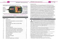
<strong>mcd99</strong>: <strong>speed</strong> <strong>controller</strong> <strong>and</strong> <strong>governor</strong><br />
operating instructions software-V22, date of issue 10 NOV 1997<br />
1<br />
2<br />
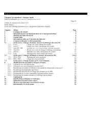
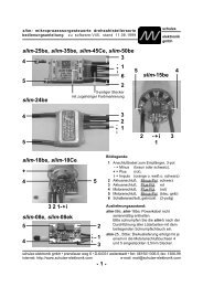
Key:<br />
1. 3 pin configuration input<br />
2. 5 pin motor sensor connector<br />
3. Receiver cable (throttle channel)<br />
4. Red/green dual color LED (on reverse)<br />
schulze<br />
elektronik<br />
gmbh<br />
page 1<br />
5. Motor connector (3 wires)<br />
6. 18 Power MOS FETs<br />
7. Protective capacitors<br />
8. Positive battery wire, RED<br />
9. Negative battery wire, BLACK<br />
Note: The unit is supplied with a set of plugs connected to socket 5.<br />
The external pushbutton for the configuration input 1. is also included<br />
3<br />
4<br />
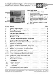
Chapter Topic Page<br />
1 Warning notes, cautions . . . . . . . . . . . . . . . . . . . . . . . . . 2<br />
2 Ensuring safe, trouble-free operation . . . . . . . . . . . . . . . . . . 3<br />
3 Range of applicatios . . . . . . . . . . . . . . . . . . . . . . . . . . . . 4<br />
4 Operating states <strong>and</strong> modes . . . . . . . . . . . . . . . . . . . . . . . 5<br />
5 Protective circuits . . . . . . . . . . . . . . . . . . . . . . . . . . . . . 6<br />
6 Variable properties, default settings . . . . . . . . . . . . . . . . . . . 7<br />
7 Special setup for helicopter use . . . . . . . . . . . . . . . . . . . . . 8<br />
8 Connections, installation . . . . . . . . . . . . . . . . . . . . . . . . . 9<br />
9 Altering the properties of the <strong>controller</strong> (= configuration process) . . . 10<br />
9.1 Symbols <strong>and</strong> terminology . . . . . . . . . . . . . . . . . . . . . . . . . . 10<br />
9.2 St<strong>and</strong>ard configuration process <strong>and</strong> “general reset” . . . . . . . . . . . . 11<br />
9.3 Property configuration process . . . . . . . . . . . . . . . . . . . . . . . 11<br />
9.3.1 Explanatory notes: the properties of the <strong>speed</strong> <strong>controller</strong> . . . . . . . . . 13<br />
10 Typical configurations . . . . . . . . . . . . . . . . . . . . . . . . . . . 14<br />
11 Connection accessoires . . . . . . . . . . . . . . . . . . . . . . . . . 16<br />
12 Legal matters . . . . . . . . . . . . . . . . . . . . . . . . . . . . . . . 17<br />
12.1 Warranty conditions . . . . . . . . . . . . . . . . . . . . . . . . . . . . 17<br />
12.2 Liability / damages . . . . . . . . . . . . . . . . . . . . . . . . . . . . . 17<br />
12.3 CE certification . . . . . . . . . . . . . . . . . . . . . . . . . . . . . . . 17<br />
13 Technical data <strong>and</strong> characteristics . . . . . . . . . . . . . . . . . . . 18<br />
schulze elektronik gmbh • prenzlauer weg 6 • D-64331 weiterstadt • tel: 06150/1306-5, fax: 1306-99<br />
internet: http://www.schulze-elektronik.com e-mail: mail@schulze-elektronik.com<br />
5<br />
6<br />
7<br />
8<br />
9
page 2<br />
1 Warning notes, cautions<br />
Electric motors fitted with propellers are dangerous<br />
<strong>and</strong> require proper care for safe operation.<br />
Keep well clear of the propeller at all times<br />
when the battery pack is connected.<br />
Technical defects of an electrical or mechanical<br />
nature may result in unintended motor runs;<br />
loose parts may cause serious personal injuriy<br />
<strong>and</strong>/or property damage.<br />
The CE-certificate on the <strong>speed</strong> <strong>controller</strong> does<br />
not absolve you from taking proper care<br />
when h<strong>and</strong>ling the system!<br />
Speed <strong>controller</strong>s <strong>and</strong> soft-switches are exclusively<br />
for use in RC models. Their use in<br />
man-carrying aircraft is prohibited.<br />
Speed <strong>controller</strong>s <strong>and</strong> softswitches are not protected<br />
against reverse polarity (+ terminal<br />
<strong>and</strong> - terminal reversed). Connecting the<br />
battery pack to the motor leads of the <strong>controller</strong><br />
or soft-switch will almost certainly<br />
cause irreparable damage.<br />
Electronic equipment is sensitive to humidity.<br />
Speed <strong>controller</strong>s <strong>and</strong> soft-switches which<br />
have got wet may not function properly even<br />
after thorough drying. You should send<br />
them back to us for cleaning <strong>and</strong> testing.<br />
Do not use <strong>mcd99</strong> in conjunction with a power<br />
supply connected to the mains. Energy reversal<br />
occurs when the motor slows down<br />
<strong>and</strong> stops, <strong>and</strong> this may damage the power<br />
supply or cause an over-voltage condition<br />
which could damage the <strong>mcd99</strong>.<br />
Check carefully that all 3 motor wires <strong>and</strong> all 5<br />
sensor wires are plugged into the correct<br />
connectors. Incorrect or incomplete connection<br />
of the power <strong>and</strong> sensor cables will damage<br />
the <strong>speed</strong> <strong>controller</strong> <strong>and</strong>/or the motor.<br />
Never disconnect the flight pack while the motor<br />
is running, as this could cause damage on<br />
the <strong>speed</strong> <strong>controller</strong> or soft-switch.<br />
Protect the <strong>speed</strong> <strong>controller</strong> or soft-switch from<br />
mechanical loads, vibration, dirt <strong>and</strong> contamination.<br />
<strong>mcd99</strong>: <strong>speed</strong> <strong>controller</strong> <strong>and</strong> <strong>governor</strong><br />
for brushless 3-phase motors<br />
Never leave the flight battery connected<br />
when ...<br />
... the model is not in use <strong>and</strong>/or<br />
... the battery pack is being charged.<br />
(Although some <strong>speed</strong> <strong>controller</strong>s feature a<br />
separate On/Off switch, this does not isolate<br />
it completely from the battery.)<br />
Do not exceed the maximum stated length of<br />
cable between battery <strong>and</strong> the <strong>mcd99</strong> (max.<br />
length: 20 cm / 7...8"). The wiring inside the<br />
battery pack must also be as short as possible.<br />
Use in-line soldered “stick” packs.<br />
For the same reason use current clamps<br />
when measuring current values rather than<br />
shunt resistors.<br />
Protect the 3-pin configuration input from shortcircuit.<br />
Speed <strong>controller</strong>s <strong>and</strong> soft-switches can only<br />
function properly if they are in full working<br />
condition. The protective <strong>and</strong> monitoring circuits<br />
can also only work if the <strong>speed</strong> <strong>controller</strong><br />
is in good operating condition.<br />
In the case of motor failure (e.g.short<br />
circuits in the windings) the over-temperature<br />
sensor in the <strong>mcd99</strong> may respond<br />
too slowly to prevent damage. If<br />
you notice reduced power due to a motor<br />
malfunction, switch off the <strong>mcd99</strong><br />
down immediately to prevent permanent<br />
damage to the propulsion system.<br />
The <strong>mcd99</strong> has no current monitoring circuitry.<br />
Note: Please remember that the monitoring circuits<br />
are unable to detect every abnormal<br />
operating condition. If the motor runs irregularly:<br />
Switch off immediately <strong>and</strong> send<br />
<strong>mcd99</strong> back to us for repair.<br />
If you are using a mechanical gyro:<br />
Always disconnect the flight pack before<br />
turning off the receiver. As the gyro runs<br />
down it may product sufficient voltage for<br />
the receiver to send an unwanted signal to<br />
the <strong>controller</strong>, <strong>and</strong> this could cause the motor<br />
to burst into life!<br />
schulze elektronik gmbh • prenzlauer weg 6 • D-64331 weiterstadt • tel: 06150/1306-5, fax: 1306-99<br />
internet: http://www.schulze-elektronik.com e-mail: mail@schulze-elektronik.com
<strong>mcd99</strong>: <strong>speed</strong> <strong>controller</strong> <strong>and</strong> <strong>governor</strong><br />
operating instructions software-V22, date of issue 10 NOV 1997<br />
2 Ensuring safe, trouble-free<br />
operation<br />
Use only compatible connectors. A 2mm pin cannot<br />
provide reliable contact in a 2.5mm socket. The<br />
same applies with 2mm gold-contact pins <strong>and</strong><br />
2mm tin-plated sockets.<br />
Please also remember that ...<br />
... the wiring of your RC-components must be chekked<br />
regularly for loose wires, oxidation, or damaged<br />
insulation, especially when using a BEC system.<br />
... all connectors must be tight <strong>and</strong> the thin sensor<br />
cables must not be kinked or broken. Do not pull at<br />
the cables when disconnecting the sensor plug. Raise<br />
the connector latch to allow the plug to be disconnected<br />
easily.<br />
... all 3 motor cables must be connected in the correct<br />
sequence. Incorrect <strong>and</strong> incomplete connection<br />
of the power <strong>and</strong> sensor cables will cause damage to<br />
the <strong>speed</strong> <strong>controller</strong> <strong>and</strong>/or the motor.<br />
... the CE certificate on the <strong>speed</strong> <strong>controller</strong> does<br />
not absolve you from the need to h<strong>and</strong>le the system<br />
carefully.<br />
... your receiver <strong>and</strong> the aerial must be at least 3<br />
cm (>1") away from motor, <strong>speed</strong> <strong>controller</strong> <strong>and</strong><br />
high-current cables.<br />
... that all cables carrying high currents are as short<br />
as possible. The length of cable between the <strong>mcd99</strong><br />
<strong>and</strong> the motor must not exceed 5 cm (2"), <strong>and</strong> the<br />
cable between the <strong>mcd99</strong> <strong>and</strong> the battery pack must<br />
not exceed 20 cm (8") (incl. the length of any cell<br />
links inside the pack).<br />
... you must solder additional protective capacitors<br />
between the battery cables close to the <strong>mcd99</strong> (no<br />
further than 2 cm (1")) if the motor current drain is<br />
higher than the nominal current value for the <strong>mcd99</strong>:<br />
2 x 470 uF/50V if cables are up to 20 cm (8") long;<br />
1 x 470 uF/50V if cables are up to 10 cm (4") long.<br />
If you keep to the 5 cm cable length limit <strong>and</strong> use inline<br />
soldered battery packs, additional capacitors are<br />
not usually needed.<br />
... all high-current cables longer than 5 cm (2")<br />
must be twisted together. This applies in particular to<br />
the motor power cables.<br />
... in model aircraft: half of the receiver aerial's length<br />
should be routed along the fuselage, the other half<br />
should be allowed to trail freely (take care not to tread<br />
on it). Do not attach the end of the aerial to the fin!<br />
... in model boats: half of the receiver aerial's<br />
length should be deployed inside the hull above the<br />
waterline, the other half should be threaded into a<br />
small tube mounted upright.<br />
schulze<br />
elektronik<br />
gmbh<br />
page 3<br />
Every time you intend to use the power system<br />
- before you turn on the receiver -<br />
make sure that ...<br />
... no one else is using the same frequency<br />
(identical channel number).<br />
... your transmitter is switched on <strong>and</strong> the<br />
throttle stick is in the STOP position.<br />
Carry out a range check before each flight. Ask<br />
an assist<strong>and</strong> to hold the model aircraft <strong>and</strong><br />
set the throttle stick to the half throttle position<br />
(full throttle if using a soft-switch). Collapse<br />
the transmitter aerial. Walk away from<br />
the model to the distance stated by the RC<br />
system manufacturer (this might be a distance<br />
of about 50-60 m = 200'). Make sure<br />
that you still have full control of the system<br />
at this range.<br />
When Ni-Cd batteries approach the end of their<br />
charge, voltage falls drastically <strong>and</strong> quickly.<br />
The <strong>mcd99</strong> detects this <strong>and</strong> reduces power<br />
to the motor automatically. This should leave<br />
sufficient energy to bring your model<br />
safely back home. However, if you use a<br />
small number of cells of high internal resistance<br />
<strong>and</strong> operate at high motor currents,<br />
the <strong>controller</strong> may reduce power before the<br />
pack is discharged. You can eliminate this<br />
problem by using low resistance straps to<br />
connect the cells, or use the direct cell-tocell<br />
soldering technique (“sticks”) <strong>and</strong> short,<br />
heavy-gauge wire if you assemble your own<br />
batteries.<br />
Be sure that you have armed the appropriate<br />
configuration. If you chose <strong>governor</strong>-mode,<br />
you must also select either aerobatic mode<br />
or helicopter mode (see chapter 9).<br />
After resetting the stick positions <strong>and</strong> <strong>controller</strong><br />
characteristics („general reset“), the <strong>mcd99</strong><br />
defaults to normal <strong>speed</strong> <strong>controller</strong> configuration.<br />
If you subsequently switch to <strong>governor</strong> mode,<br />
the <strong>mcd99</strong> will switch to helicopter-optimized<br />
configuration. If you wish to use the <strong>mcd99</strong><br />
in an aerobatic fixed-wing aircraft, you must<br />
re-configure the <strong>controller</strong> to optimize it for<br />
your model (see Chapters 7 <strong>and</strong> 9).<br />
schulze elektronik gmbh • prenzlauer weg 6 • D-64331 weiterstadt • tel: 06150/1306-5, fax: 1306-99<br />
internet: http://www.schulze-elektronik.com e-mail: mail@schulze-elektronik.com
page 4<br />
3 Range of applications<br />
Type of motor:<br />
The <strong>mcd99</strong> series of <strong>controller</strong>s is designed to<br />
work with three phase brushless motors. All<br />
motors must have three internal sensors to detect<br />
the actual position of the rotor <strong>and</strong> pass it<br />
to the <strong>mcd99</strong>. This guarantees stable operation<br />
under all conditions of rotation <strong>speed</strong> <strong>and</strong> load.<br />
Compatible motors are available from: Aveox,<br />
Graupner, Köhler, Kontronik, Plettenberg.<br />
Type of model (radio-controlled only):<br />
Range of applications:<br />
Aircraft (e.g. hot-line fixed wing with/without<br />
gearbox <strong>and</strong> folding propeller; aerobatic model<br />
with fixed propeller, <strong>controller</strong> or <strong>governor</strong><br />
mode) <strong>and</strong><br />
Helicopters (brake off, <strong>controller</strong> or <strong>governor</strong><br />
mode) <strong>and</strong><br />
Cars <strong>and</strong> Boats (with forward <strong>and</strong> reverse<br />
running). Note that the <strong>controller</strong>s does not<br />
feature waterproof seals, as provided by the<br />
b40, b50 und mcc1010 series.<br />
Specification:<br />
Common Data:<br />
Modes: <strong>controller</strong> or <strong>governor</strong><br />
Separation from receiver <strong>and</strong> load circuitry:<br />
by optocoupler<br />
Low weight: by compact design<br />
<strong>mcd99</strong>-33bo/E:<br />
Number of cells/type: 6 to 24/Ni-Cd<br />
Low voltage limit: approx. 5V<br />
Application range:<br />
low <strong>and</strong> middle power applications<br />
Special features:<br />
- voltage increasing circuit which generates<br />
a auxiliary voltage supply for all 18 low resistance<br />
Power MOS FETs.<br />
- low budget price<br />
<strong>mcd99</strong>-33bo:<br />
Number of cells/type: 14 to 32/Ni-Cd<br />
Low voltage limit: approx. 12V<br />
Application range: low <strong>and</strong> middle<br />
power applications<br />
Special features: low budget price<br />
<strong>mcd99</strong>: <strong>speed</strong> <strong>controller</strong> <strong>and</strong> <strong>governor</strong><br />
for brushless 3-phase motors<br />
<strong>mcd99</strong>-40bo/E:<br />
Number of cells/type: 6 to 24/Ni-Cd<br />
Low voltage limit: approx. 5V<br />
Application range:<br />
for all applications<br />
Special features:<br />
- voltage increasing circuit<br />
- high maximum current capability<br />
<strong>mcd99</strong>-40bo:<br />
Number of cells/type: 14 to 32/Ni-Cd<br />
Low voltage limit: approx. 12V<br />
Application range:<br />
for all applications<br />
Special features:<br />
high maximum current capability<br />
<strong>mcd99</strong>-45bo/E:<br />
Number of cells/type: 6 to 24/Ni-Cd<br />
Low voltage limit: approx. 5V<br />
Application range:<br />
for all applications <strong>and</strong> F5B/E-contests<br />
Special features:<br />
- voltage increasing circuit<br />
- extra high maximum current capability<br />
<strong>mcd99</strong>-45bo:<br />
Number of cells/type: 14 to 32/Ni-Cd<br />
Low voltage limit: approx. 12V<br />
Application range:<br />
for all applications <strong>and</strong> F5B-contests<br />
Special features:<br />
- extra high maximum current capability<br />
- used in last world championship!<br />
<strong>mcd99</strong>-50bo/E:<br />
Number of cells/type: 6 to 14/Ni-Cd<br />
Low voltage limit: approx. 5V<br />
Application range:<br />
for all applications <strong>and</strong> F5B/E-contests<br />
Special features:<br />
- voltage increasing circuit<br />
- highest maximum current capability<br />
<strong>mcd99</strong>-51bo/E:<br />
same as <strong>mcd99</strong>-50bo/E, but:<br />
Number of cells/type: 6 to 21/Ni-Cd<br />
schulze elektronik gmbh • prenzlauer weg 6 • D-64331 weiterstadt • tel: 06150/1306-5, fax: 1306-99<br />
internet: http://www.schulze-elektronik.com e-mail: mail@schulze-elektronik.com
<strong>mcd99</strong>: <strong>speed</strong> <strong>controller</strong> <strong>and</strong> <strong>governor</strong><br />
operating instructions software-V22, date of issue 10 NOV 1997<br />
4 Operating states <strong>and</strong> modes<br />
Operating state: “awaiting comm<strong>and</strong>”:<br />
This state occurs if you ...<br />
... connect the <strong>mcd99</strong> to the battery when the<br />
transmitter stick is in the “motor on” range, or<br />
... press the comm<strong>and</strong> button when the motor is<br />
turning slowly, when the <strong>mcd99</strong> is already armed.<br />
Indication: Both LEDs flash alternately at low rate.<br />
Operating state “armed” (ready to use):<br />
In this state the <strong>mcd99</strong> can control or regulate the<br />
motor according to its default or configured characteristics<br />
(See Chapter 6).<br />
The <strong>mcd99</strong> is armed if...<br />
... the “auto-arm” (automatic) function is effective<br />
<strong>and</strong> the stick is at the “idle“ or “brake“ position for<br />
longer than 2 seconds after you connect the battery<br />
or complete a re-configuration process.<br />
... the “manual-arm” function is effective <strong>and</strong> the<br />
stick is at the “idle“ or “brake“ position <strong>and</strong> you<br />
hold the button pressed for longer than 2 seconds<br />
<strong>and</strong> less then 4 seconds after pressing<br />
the comm<strong>and</strong> button.<br />
Indication:<br />
Throttle stick at neutral: both LEDs flash alternately<br />
at high rate.<br />
Throttle stick at brake position: green LED flashes<br />
at high rate.<br />
Operating state “safe” (disarmed):<br />
This condition prevails when you are configuring the<br />
<strong>controller</strong>. In this state the <strong>mcd99</strong> cannot receive or<br />
process control signals.<br />
The <strong>mcd99</strong> will be disarmed if ...<br />
... the “manual-arm” function is effective <strong>and</strong> you<br />
press the comm<strong>and</strong> button for less than 1 sec.<br />
... the “auto-arm” (automatic) function is effective<br />
<strong>and</strong> you press the comm<strong>and</strong> button for<br />
less then 1 second <strong>and</strong> the throttle channel<br />
is in any “motor on” position (i.e. not at the<br />
idle or brake setting).<br />
The <strong>mcd99</strong> stays disarmed if the “auto-arm”<br />
function is effective, if...<br />
... the drive battery is connected <strong>and</strong> the stick is in a<br />
“motor on“ position.<br />
... the stick is at a “motor on” position at the end of<br />
the configuration process.<br />
schulze<br />
elektronik<br />
gmbh<br />
page 5<br />
“Configuration” mode:<br />
Here we have to differentiate between the st<strong>and</strong>ard<br />
configuration process <strong>and</strong> the property<br />
configuration process.<br />
In the st<strong>and</strong>ard configuration process you can ...<br />
... reset all the unit's properties to the factory<br />
default values (general reset)<br />
und / oder<br />
... set the brake, idle <strong>and</strong> full throtte positions<br />
of the throttle stick.<br />
In the property configuration process you can ...<br />
... set the (main) mode of operation (see below)<br />
<strong>and</strong> many associated properties of the <strong>controller</strong><br />
(Chapter 9).<br />
Alternatively you can use the optional “flysoft”<br />
software, which gives you simple access to all<br />
points of a configuration, accurate to a single bit.<br />
“Normal <strong>speed</strong> <strong>controller</strong>” mode:<br />
When used as a <strong>speed</strong> <strong>controller</strong> the <strong>mcd99</strong><br />
passes a voltage to the motor corresponding to<br />
the stick position, without making adjustments<br />
to allow for load changes.<br />
“Speed <strong>governor</strong>” mode:<br />
When used as a <strong>speed</strong> <strong>governor</strong> the <strong>mcd99</strong> detects<br />
changes in load <strong>and</strong> regulates the power<br />
fed to the motor to compensate for those changes.<br />
The result is constant rotational <strong>speed</strong>, because<br />
the motor always receives the appropriate<br />
current to suit the load.<br />
In this mode of operation the <strong>mcd99</strong> operates as a<br />
st<strong>and</strong>ard <strong>speed</strong> <strong>controller</strong> to run the motor up to nominal<br />
<strong>speed</strong>, then switches over to <strong>governor</strong> mode.<br />
Indication: in <strong>governor</strong> mode the unit's red <strong>and</strong> green<br />
LEDs are on constantly <strong>and</strong> simultaneously.<br />
It is essential to set the correct optimization (see configuration<br />
process) to suit the type of model you are<br />
using (helicopter or aerobatic fixed wing).<br />
“Car <strong>controller</strong>” mode:<br />
As “normal <strong>speed</strong> <strong>controller</strong>”, but with reverse<br />
running <strong>and</strong> proportional braking for both directions<br />
or rotation.<br />
You can only run the motor in reverse after applying<br />
full brake for a short period. After a (programmable)<br />
waiting period the “brake” range of stick then serves<br />
as a proportional control for reverse running. During<br />
this period (forward) throttle range acts as a brake<br />
until the model comes to a halt, after which it switches<br />
back to forward running.<br />
schulze elektronik gmbh • prenzlauer weg 6 • D-64331 weiterstadt • tel: 06150/1306-5, fax: 1306-99<br />
internet: http://www.schulze-elektronik.com e-mail: mail@schulze-elektronik.com
page 6<br />
5 Protective circuits<br />
Note:<br />
Please remember that the monitoring circuits<br />
are unable to detect every abnormal<br />
operating condition. If the motor runs irregularly:<br />
switch off immediately <strong>and</strong> send the<br />
<strong>mcd99</strong> back to us for repair.<br />
Temperature monitor:<br />
Temperature monitor circuit reduces motor<br />
current in two steps before cutting it off<br />
completely. When the temperature has fallen<br />
sufficiently, you can re-start the motor<br />
after leaving the throttle stick in the “idle” or<br />
“brake” positions for about 2 seconds. This<br />
also works when the <strong>mcd99</strong> is in “manualarm”<br />
mode.<br />
In the case of a motor failure (e.g.<br />
short circuits in the windings) the overtemperature<br />
sensor in the <strong>mcd99</strong> may<br />
respond too slowly to prevent damage.<br />
If you notice reduced power due to a<br />
motor malfunction, switch off the<br />
<strong>mcd99</strong> immediately to prevent permanent<br />
damage to the propulsion system.<br />
Low voltage monitor:<br />
This feature automatically reduces motor<br />
power when the battery voltage falls to the<br />
lower limit of the voltage range. The user<br />
can vary the limit voltage as part of the configuration<br />
process: either the <strong>controller</strong>'s minimum<br />
operating voltage or to the minimum<br />
voltage of the battery pack in use.<br />
Once the <strong>controller</strong> has detected a voltage<br />
rise, the motor may be re-started after leaving<br />
the throttle stick in the “idle” or “brake”<br />
positions for about 2 seconds. This also<br />
works when the <strong>mcd99</strong> is in “manual-arm”<br />
mode.<br />
<strong>mcd99</strong>: <strong>speed</strong> <strong>controller</strong> <strong>and</strong> <strong>governor</strong><br />
for brushless 3-phase motors<br />
Current monitor:<br />
This <strong>speed</strong> <strong>controller</strong> is not current-limited.<br />
It is not able to detect a condition<br />
where the current drain is higher<br />
than the specified current.<br />
Reverse polarity protection:<br />
The mcd 99 is not protected against<br />
reverse polarity.<br />
Watchdog:<br />
The watchdog circuit detects any irregularities<br />
in operation <strong>and</strong> signals a problem by<br />
interrupting power to the motor briefly.<br />
Lost receiver signal detection:<br />
If the receiver signal fails or is abnormal, the<br />
<strong>speed</strong> <strong>controller</strong> holds the last received signal<br />
for 100ms, then switches the motor off.<br />
schulze elektronik gmbh • prenzlauer weg 6 • D-64331 weiterstadt • tel: 06150/1306-5, fax: 1306-99<br />
internet: http://www.schulze-elektronik.com e-mail: mail@schulze-elektronik.com
<strong>mcd99</strong>: <strong>speed</strong> <strong>controller</strong> <strong>and</strong> <strong>governor</strong><br />
operating instructions software-V22, date of issue 10 NOV 1997<br />
6 Variable properties,<br />
default settings<br />
The <strong>mcd99</strong> is a multi-purpose <strong>speed</strong> <strong>controller</strong>. It is<br />
possible to alter certain of its properties by a configuration<br />
process to optimize it for use as a normal<br />
<strong>speed</strong> <strong>controller</strong>, a reversing <strong>speed</strong> <strong>controller</strong> or a<br />
<strong>speed</strong> <strong>governor</strong> (regulator).<br />
The <strong>mcd99</strong> is configured at the factory in default<br />
mode; changing the operation mode is done by<br />
changing the unit's configuration. The table shows<br />
the features of the <strong>mcd99</strong> which can be altered; note<br />
that the factory default values are underlined.<br />
If you have configured the <strong>mcd99</strong> to suit a certain<br />
model <strong>and</strong> want to change to a different model at a<br />
later date (<strong>and</strong> in the meantime you may have forgotten<br />
the exact configuration of the <strong>mcd99</strong>) than<br />
you can easily perform a “general reset” which returns<br />
the <strong>mcd99</strong> to the factory default settings.<br />
You can configure the <strong>mcd99</strong> using -<br />
- the transmitter throttle stick <strong>and</strong> the external<br />
comm<strong>and</strong> button supplied with the <strong>controller</strong>.<br />
- the throttle stick <strong>and</strong> the external button/voltmeter<br />
combination („tast-vm“, optional)<br />
- a PC, using the schulze-software “flysoft” <strong>and</strong> a<br />
suitable adapter cable „prog-adapt“ (all optional).<br />
The cable attached to the push-button or the cable<br />
of the button/voltmeter can be connected directly to<br />
the <strong>mcd99</strong> (observe polarity = color codes). Alternatively,<br />
the PC adapter cable can be connected directly<br />
to the <strong>mcd99</strong> (<strong>and</strong> to the receiver).<br />
Parameters are configured in groups, <strong>and</strong> these are<br />
marked by thick outlines in the table.<br />
Note:<br />
Chapter 9 includes more details about changing the<br />
configuration of the <strong>mcd99</strong>.<br />
If you accidentally store an incorrect value in the<br />
<strong>mcd99</strong>, you can ab<strong>and</strong>on the entry by setting it to<br />
“full brake” (throttle stick at minimum) then pressing<br />
the button several times until the unit returns to the<br />
“awaiting comm<strong>and</strong>” state. This procedure takes<br />
care that all other values following the incorrect, are<br />
not changed. You can now try again.<br />
Note: you can achieve the same result by disconnecting<br />
the <strong>mcd99</strong> from the battery.<br />
Parameter Note<br />
Brake position (BP)<br />
Neutral position (NP)<br />
Full throttle posit. (FP)<br />
Throttle acceleration (+)<br />
Brake delay (-)<br />
Activation<br />
Low voltage protection<br />
Direction motor rotation<br />
(in flight-/drive-direction)<br />
Governor gain control<br />
Maximum pulses<br />
per minute when<br />
Throttle stick=Full throttle<br />
Divisor factor hardware<br />
Resulting rpm<br />
see table in<br />
chapter 9.3.1<br />
page 13<br />
schulze<br />
elektronik<br />
gmbh<br />
page 7<br />
BP und NP<br />
can be<br />
identical.<br />
If BP between<br />
NP <strong>and</strong> FP:<br />
brake deactivated!<br />
variable:<br />
1.1s, 930, 780,<br />
630, 570, 450,<br />
390, 330, 270,<br />
-180, 150,+120,<br />
90, 60 ms<br />
man. / autom.<br />
10%...20%...50%<br />
schulze elektronik gmbh • prenzlauer weg 6 • D-64331 weiterstadt • tel: 06150/1306-5, fax: 1306-99<br />
internet: http://www.schulze-elektronik.com e-mail: mail@schulze-elektronik.com<br />
Governor Mode<br />
Car Mode<br />
op. mode<br />
Minimum throttle<br />
Min. brake effect<br />
Max. brake effect<br />
Reverse delay<br />
battery voltage<br />
or 5V/12V<br />
reverse = CCW<br />
forward = CW<br />
1:2; 1:8 caution!<br />
0%...50% Power<br />
0%...100% Brake<br />
0%...100% Brake<br />
0s...1.5s...4.5s,<br />
reverse off<br />
Car <strong>controller</strong> with reverse function<br />
Governor for helicopter/aerobatic use<br />
Normal <strong>controller</strong><br />
Optimizing <strong>governor</strong> for aerobatic or heli<br />
Calibration of voltmeter test equipment<br />
St<strong>and</strong>ard Config.<br />
Application Configuration
page 8<br />
7 Special setup for<br />
helicopter use<br />
IIn a model helicopter you can use the <strong>mcd99</strong> as a<br />
<strong>speed</strong> <strong>controller</strong> or a genuine <strong>speed</strong> <strong>governor</strong>.<br />
Please note very carefully the differences between<br />
the two modes relaiting to programming the throttle<br />
channel at the transmitter.<br />
A. Speed <strong>controller</strong> mode:<br />
Connect the servo lead to the throttle channel which<br />
would normally use the st<strong>and</strong>ard 3-point or 5-point<br />
throttle curve to control a throttle servo (for a glow<br />
motor). With this arrangement the <strong>mcd99</strong> setting varies<br />
according to the collective pitch setting.<br />
Disadvantage: this system requires accurate adjustment<br />
of the throttle curve for constant system rotational<br />
<strong>speed</strong>.<br />
Before you carry out the configuration process<br />
as described in Chapter 9, please note<br />
the following points:<br />
Although glow-powered helicopters (<strong>and</strong> over-powered<br />
electric helicopters) hover at half throttle, most<br />
electric helicopters hover at around 75-85% throttle,<br />
depending on model type <strong>and</strong> equipment.<br />
Only for the last mentioned, the st<strong>and</strong>ard transmitter<br />
trim facilities are often useless in this situation, as<br />
there is insufficient trim range when the neutral position<br />
is set to hover throttle. You can avoid this problem<br />
by offsetting the hover throttle point in your<br />
transmitter as follows:<br />
1. Increase servo travel in the “motor stopped” direction<br />
to 150%<br />
2. Reduce servo travel in the “full throttle” direction<br />
to 50%.<br />
Once you have done this you will be able to exploit<br />
your transmitter's trim facilities to fine-tune your helicopter.<br />
Idle up:<br />
Set the idle up function so that the motor still receives<br />
a small throttle signal when the motor is in a<br />
steep descent.<br />
B. Speed <strong>governor</strong> mode:<br />
Connect the servo lead to a channel which is controlled<br />
by a rotary or slide potentiometer in the transmitter,<br />
<strong>and</strong> which is not influenced by any mixed<br />
function. For example, if you have an mc-18 or mc-<br />
<strong>mcd99</strong>: <strong>speed</strong> <strong>controller</strong> <strong>and</strong> <strong>governor</strong><br />
for brushless 3-phase motors<br />
20 system use channel 8.<br />
You can now start the motor with this channel <strong>and</strong><br />
set a rotational <strong>speed</strong> which is maintained automatically<br />
in flight, even under varying load conditions.<br />
Setting up the channel:<br />
The servo travel settings for the <strong>speed</strong> control channel<br />
in the transmitter should be +/- 100%.<br />
Carry out the st<strong>and</strong>ard configuration process for the<br />
<strong>mcd99</strong> (see Chapter 9.2)<br />
Set the “<strong>speed</strong> <strong>governor</strong>” mode in the property configuration<br />
process (see Chapter 9.3).<br />
Optimize the <strong>controller</strong> for “helicopter” (see Chapter<br />
9.3).<br />
Set the <strong>mcd99</strong> to the maximum permissible rotational<br />
<strong>speed</strong>. For example, with a gearbox reduction<br />
ratio of 1:10 <strong>and</strong> a rotor <strong>speed</strong> of 1500 rpm this<br />
equates to a motor <strong>speed</strong> of 15,000 rpm for cruising<br />
<strong>and</strong> aerobatics.<br />
The slider controlling channel 8 can now be used to<br />
set the motor <strong>speed</strong> to any point in the range 0 to<br />
15,000 rpm.<br />
A st<strong>and</strong>ard feature of the <strong>mcd99</strong> is a non-variable<br />
fixed-period softstart, <strong>and</strong> this prevents abrupt changes<br />
in rotational <strong>speed</strong> when you alter the nominal<br />
rotation <strong>speed</strong>.<br />
The minimum rotational <strong>speed</strong> which you can set in<br />
<strong>governor</strong> mode is about 1/3 of the maximum <strong>speed</strong><br />
you have already set in configuration process.<br />
When you start the motor the <strong>mcd99</strong> initially operates<br />
in st<strong>and</strong>ard <strong>speed</strong> <strong>controller</strong> mode, raising rotational<br />
<strong>speed</strong> to the minimum governed <strong>speed</strong>. It then<br />
switches to <strong>governor</strong> mode after a delay of about 5<br />
seconds.<br />
Idle-up settings (pre-set rotational <strong>speed</strong>s):<br />
a. The <strong>mcd99</strong> reverts to st<strong>and</strong>ard <strong>controller</strong> mode<br />
as soon as the throttle stick is moved below the 15%<br />
mark. You can prevent this occuring by mixing in<br />
15% (or more) throttle before take-off using the trim<br />
slider or the idle-up function (toggle switch).<br />
b. If your model hovers at a lower rotational <strong>speed</strong><br />
than stated above (e.g. 11,250 rpm at the motor),<br />
you will only need to turn back the <strong>speed</strong> pre-set pot<br />
(channel 8) by a quarter of its travel. Alternatively you<br />
can program a seperate toggle switch on the transmitter<br />
to provide a travel reduction of 1/4 of total travel<br />
for channel 8 (= 50% from centre).<br />
schulze elektronik gmbh • prenzlauer weg 6 • D-64331 weiterstadt • tel: 06150/1306-5, fax: 1306-99<br />
internet: http://www.schulze-elektronik.com e-mail: mail@schulze-elektronik.com
<strong>mcd99</strong>: <strong>speed</strong> <strong>controller</strong> <strong>and</strong> <strong>governor</strong><br />
operating instructions software-V22, date of issue 10 NOV 1997<br />
8 Connections, installation<br />
Receiver connection:<br />
Provides that your model is a car, boat or fixedwing<br />
aircraft, simply connect the receiver cable<br />
attached to the <strong>mcd99</strong> to the throttle channel in<br />
the usual way.<br />
If your model is a helicopter, please refer to<br />
Chapter 7.<br />
Length of battery cable:<br />
The maximum length of cable to the flight/drive<br />
battery is 20 cm (7")! If you use a longer cable<br />
<strong>and</strong> then use the <strong>controller</strong>, first the protective capacitors<br />
will explode, then the electronics will burn<br />
out, as they are no longer protected. One test run<br />
is enough!<br />
Connector types:<br />
Please note that your guarantee is invalid unless<br />
you use polarized gold-plated connectors.<br />
Suitable connectors:<br />
- Conzelmann CT4 system (4 mm)<br />
- schulze perfect plug 35 - system (3.5mm)<br />
also used on the motor connections.<br />
Completing the connections using the CT4<br />
or similar 4mm system:<br />
<strong>mcd99</strong> battery cable:<br />
a. Red positive cable: push the wire through the<br />
narrow part of the plastic housing from the fluted<br />
side, then solder the female socket on the end.<br />
b. Black negative wire: push the wire through<br />
the wide part of the plastic housing from the fluted<br />
side, then solder the male plug on the end.<br />
c. Place the<br />
socket part on<br />
the jaws of a<br />
vice <strong>and</strong> close<br />
the jaws to the<br />
point where the<br />
cable can still<br />
just move.<br />
d. Using a plug<br />
as a guide, use<br />
a hammer to<br />
socket<br />
positive<br />
(red)<br />
tap the socket into the housing.<br />
plug<br />
negative<br />
(black)<br />
schulze<br />
elektronik<br />
gmbh<br />
page 9<br />
e. Using a socket as a<br />
guide, use a hammer<br />
to tap the plug into the<br />
housing.<br />
See d.<br />
<strong>mcd99</strong> motor:<br />
See e.<br />
Connect the cables following<br />
the colour coding<br />
on the sticker.<br />
- Blue or black motor wire to the black / blue mark<br />
(marker: on the side of the black battery cable)<br />
- Yellow or green motor cable to the green / yellow<br />
mark, centre contact<br />
- Red motor cable to the red mark (marker: on<br />
the side of the red battery cable) (note: Koehler<br />
motors: green cable).<br />
Although the connectors are very secure we recommend<br />
that you wrap fibre-reinforced tape<br />
round the motor plugs for peace of mind.<br />
To minimize interference problems the cables attached<br />
to the motor should be kept as short as<br />
possible.<br />
Connecting the motor sensors to the <strong>mcd99</strong>:<br />
Locate the polarized plug connected to the<br />
motor's rotational <strong>speed</strong> (rotational position) sensors<br />
<strong>and</strong> connect it to the 5-pin socket on the<br />
<strong>mcd99</strong> (Koehler motors: see Chapter 1).<br />
Installation in the model's fuselage:<br />
The ideal method of securing the <strong>controller</strong> in the<br />
fuselage is to use Velcro (hook <strong>and</strong> loop) tape.<br />
Avoid any method which allows a build-up of heat<br />
in the <strong>mcd99</strong>. On no account wrap it completely<br />
in foam rubber.<br />
Connecting the push-button to the <strong>mcd99</strong>:<br />
You only need to connect the push-button or the “tastvm”<br />
(see below) when you want to make changes to<br />
the <strong>speed</strong> <strong>controller</strong>s properties (see Chapter 9), or if<br />
the button is to be used as an arming button. In this<br />
case it should be mounted in the fuselage.<br />
Connect the st<strong>and</strong>ard push-button (supplied) or<br />
the combination push-button / voltmeter (“tastvm”)<br />
to the 3-pin connector.<br />
If you are using the “tast-vm” it is important to<br />
keep to the colour coding of the 3-pin connector<br />
(see sticker on the unit).<br />
schulze elektronik gmbh • prenzlauer weg 6 • D-64331 weiterstadt • tel: 06150/1306-5, fax: 1306-99<br />
internet: http://www.schulze-elektronik.com e-mail: mail@schulze-elektronik.com
page 10<br />
9 Altering the properties<br />
(configuration process)<br />
Note:<br />
If you are using the <strong>mcd99</strong> in an electric model<br />
helicopter, please turn on Chapter 7: “Special<br />
setup for helicopter use”. If not, then read on:<br />
9.1 Symbols <strong>and</strong> terminology<br />
Stick:<br />
The throttle stick on the transmitter.<br />
0% = minimum, stick usually pointing towards<br />
you; 100%=maximum, stick usually pointing<br />
away from you.<br />
Brake position (abbreviation: BP):<br />
Position of the throttle stick where the motor<br />
stops.<br />
Symbol:<br />
Neutral position (abbreviation: NP):<br />
Idle position, or position where the motor just<br />
barely runs<br />
Symbol:<br />
Full-throttle position (abbreviation: FP):<br />
100% voltage passed to the motor (<strong>speed</strong> <strong>controller</strong><br />
mode), maximum configured motor rpm<br />
(<strong>governor</strong> mode).<br />
Symbol:<br />
Throttle position:<br />
The stick position is defined as 1...100% throttle.<br />
Symbol:<br />
(Also used to<br />
select an application)<br />
<strong>mcd99</strong>: <strong>speed</strong> <strong>controller</strong> <strong>and</strong> <strong>governor</strong><br />
for brushless 3-phase motors<br />
Configuration:<br />
Changing parameter settings to suit your application.<br />
LED indicators:<br />
LED full on<br />
LED full off<br />
LED flashing (slow rate)<br />
LED flashing (high rate)<br />
Using the push-button:<br />
Hold button pressed in<br />
(for specified duration)<br />
Release button<br />
Push button down <strong>and</strong><br />
release immediately<br />
schulze elektronik gmbh • prenzlauer weg 6 • D-64331 weiterstadt • tel: 06150/1306-5, fax: 1306-99<br />
internet: http://www.schulze-elektronik.com e-mail: mail@schulze-elektronik.com<br />
Wait<br />
or<br />
You can alter the settings of the <strong>mcd99</strong> in two<br />
ways: please see chapters 9.2 (st<strong>and</strong>ard configuration)<br />
<strong>and</strong> 9.3 (application configuration):
<strong>mcd99</strong>: <strong>speed</strong> <strong>controller</strong> <strong>and</strong> <strong>governor</strong><br />
operating instructions software-V22, date of issue 10 NOV 1997<br />
9.2 St<strong>and</strong>ard configuration process <strong>and</strong><br />
general reset<br />
a. Resets the <strong>mcd99</strong> to factory defaults (“general<br />
reset”), which is useful if you become confused<br />
at some stage in the programming sequence.<br />
See the table in Chapter 6.<br />
b. Program the stick positions for brake, idle <strong>and</strong><br />
maximum rpm. Caution: If you only wish to perform<br />
a “general reset” you must disconnect power<br />
from the <strong>mcd99</strong> when the red light flashes.<br />
1a. 1b.<br />
Einschalten Einschalten Receiver<br />
3.<br />
2a.<br />
2b.<br />
2a. <strong>and</strong> 2b. simultaneously!<br />
Note re. 2b.:<br />
I. > 30seconds: performs "general reset"<br />
II. >2sec,
schulze elektronik gmbh • prenzlauer weg 6 • D-64331 weiterstadt • tel: 06150/1306-5, fax: 1306-99<br />
internet: http://www.schulze-elektronik.com e-mail: mail@schulze-elektronik.com<br />
5s<br />
8s<br />
11s<br />
Car Mode only<br />
11s<br />
Governor Mode<br />
14s<br />
17s<br />
low<br />
throttle<br />
LEDs<br />
red green<br />
red green<br />
red green<br />
red green<br />
red green<br />
red green<br />
LEDs<br />
red<br />
red<br />
green<br />
green<br />
green<br />
neutral 1s...60ms<br />
throttle-acceleration<br />
green<br />
actual<br />
value<br />
actual<br />
value<br />
0=see<br />
table of<br />
time-values<br />
manual<br />
(by<br />
key)<br />
auto<br />
on<br />
activation mode<br />
select<br />
minimum-throttle (motorvoltage)<br />
red<br />
red<br />
0%, 5% ... 100%<br />
stick position:<br />
0%, 50%, 100%<br />
stick position:<br />
actual<br />
value<br />
0% ... 50%<br />
of<br />
batteryvoltage<br />
stick position:<br />
0%, 5...40...100%<br />
actual<br />
value<br />
gain control of <strong>governor</strong><br />
actual<br />
value<br />
10% ... 50%<br />
convenient:<br />
20%<br />
stick position:<br />
car-<strong>controller</strong><br />
<strong>governor</strong><br />
norm.<br />
<strong>controller</strong><br />
mode of operation<br />
stick position:<br />
without effect<br />
<strong>mcd99</strong><br />
gives 0.5V:<br />
“tast-vm” shows<br />
1/2 deflection<br />
LEDs<br />
red<br />
green<br />
0%, 5% ... 100%<br />
neutral 1s...60ms<br />
actual<br />
value<br />
see<br />
table of<br />
time-values<br />
brake-delay<br />
stickposition:<br />
0%, 50%, 100%<br />
actual<br />
value<br />
by<br />
batt.volt.<br />
minimum<br />
(5V/<br />
12V)<br />
LEDs<br />
select red green<br />
select<br />
ready<br />
actual refore- value verseward (CCW) (CW)<br />
low voltage cutoff direction of motor rotation<br />
stickposition:<br />
actual<br />
value<br />
0% ... 100%<br />
brake<br />
effect<br />
minimum brake effect<br />
actual<br />
value<br />
stickposition:<br />
0%, 50%, 100%<br />
stickposition:<br />
0%,5%...100%<br />
actual<br />
value<br />
0 ... 100%<br />
brake<br />
effect<br />
maximum brake effect<br />
select<br />
select red green<br />
select<br />
actual<br />
1:2<br />
value<br />
ATTEN<br />
TION<br />
max. pulses/min (rpm) divisor factor of divisor-hardware<br />
ready<br />
adjustment<br />
only<br />
possible<br />
in <strong>governor</strong><br />
mode<br />
green stickposition:<br />
0%, 10...25...100%<br />
6´000<br />
31´000<br />
131´000<br />
stickposition:<br />
0%, 50%, 100%<br />
1:8<br />
LEDs<br />
red green<br />
select red green select red green select red green<br />
red green 0%, 5% ... 100% select red green 0%, 5% ... 100% select red green<br />
select<br />
red<br />
red green 0%, 33, 66, 100% select red green<br />
stick position:<br />
0%, 50%, 100%<br />
actual acroheli- value aircopcraftter calibration of "tast-vm" model-type optimization<br />
select<br />
red green<br />
ready<br />
Configuration<br />
table 9.3<br />
ready<br />
red green<br />
red green<br />
Configuration<br />
finished: “ready”<br />
A Activation<br />
1. Choose neutral- or<br />
brake position<br />
2a. When Auto-On:<br />
Wait for 2 seconds<br />
2b. When Manual-On:<br />
Push button for<br />
2 seconds<br />
delay time before reverse drive<br />
ready<br />
Legend LED on LED blinks<br />
LED flickers LED off<br />
The underlined values are the predefined values after a<br />
“general reset”.<br />
actual value:<br />
old, actual valid value<br />
stickposition:<br />
0%,5%...100%<br />
actual<br />
value<br />
0..1.5..10s<br />
delaytime<br />
select<br />
red green<br />
ready<br />
3. <strong>mcd99</strong> is armed<br />
In neutral position: red<br />
und green LED flash<br />
alternately at high rate<br />
In brake position: red<br />
LED off, green LED<br />
flashes<br />
OR<br />
B Continuing<br />
configuration<br />
1. choose throttle<br />
position<br />
2. push button for 5, 8,<br />
11, 14 or 17s<br />
Continue<br />
configuration with<br />
right second value<br />
page 12<br />
<strong>mcd99</strong>: <strong>speed</strong> <strong>controller</strong> <strong>and</strong> <strong>governor</strong><br />
for brushless 3-phase motors
schulze elektronik gmbh • prenzlauer weg 6 • D-64331 weiterstadt • tel: 06150/1306-5, fax: 1306-99<br />
internet: http://www.schulze-elektronik.com e-mail: mail@schulze-elektronik.com<br />
9.3.1 Explanatory notes: the properties of the <strong>mcd99</strong> <strong>speed</strong> <strong>controller</strong><br />
- When the red <strong>and</strong> green LEDs are flashing slowly <strong>and</strong> alternately, the <strong>controller</strong>'s status is “awaiting comm<strong>and</strong>”. In this mode you can select any of several<br />
parameters <strong>and</strong> alter them. This is done by holding the button pressed in (the comm<strong>and</strong> button or “tast-vm” must be connected).<br />
- If a voltmeter is connected, the idle / brake position always shows the currently set value, <strong>and</strong> the <strong>controller</strong> then accepts this value if you simple press the button<br />
again (especially if you decide not to alter a parameter value).<br />
- You can set any of the following 16 time values for “throttle acceleration” <strong>and</strong> “brake delay” if you hold the button pressed in for 5 seconds:<br />
10% throttle=1080ms, 930, 780, 630, 570, 510, 450, 390, 330, 270, 210, 180, 150, 120, 90, 60=100% throttle (best set using a voltmeter)<br />
- Low-voltage monitor motor cut-off characteristic with failing battery voltage (button is pressed in for 8 seconds):<br />
No. of cells: when battery voltage falls about 50% of initial voltage, the <strong>controller</strong> reduces voltage to the motor until voltage rises to 50% again. Controller cuts motor<br />
off only if the 50% value cannot be maintained.<br />
- Motor cut-off at minimum permissible operation voltage: occurs at about 5V with .../E types, at about 12V with all other types.<br />
“Auto-arm” function resets low voltage / temperature monitor when required. To do this: move throttle stick to the idle position, wait at least 2 seconds, “auto-arm”<br />
function resets (also when “manual-arm” function is active!). Moderate throttle advance is recommended to avoid tripping the low voltage (or temperature) cut-off again.<br />
- Minimum throttle (1st configuration value, button pressed in for 11 seconds, “car <strong>controller</strong>” mode only):<br />
For some applications it is desirable for a particular throttle setting to be regarded as the minimum. When you advance the throttle, the motor then starts immediately<br />
at a throttle value above minimum. This means that the stick's travel between the idle <strong>and</strong> full throttle position works at even higher resolution.<br />
- Minimum braking effect (2nd configuration value, button pressed in for 11 seconds, “car <strong>controller</strong>” mode only):<br />
For some applications it is useful to set up a non-linear braking effect. For example, if you wish to implement gentle automatic braking before entering a turn, you<br />
should raise the minimum braking effect (e.g. to 10%) <strong>and</strong> then move the throttle trim on your transmitter to the “brake” area when driving. The car will then brake<br />
automatically at your selected rate of 10% when you move the throttle stick to neutral.<br />
- Maximum braking effect (3rd configuration value, button pressed in for 11 seconds, “car <strong>controller</strong>” mode only):<br />
On tracks where grip (adhesion) is relatively low, you can avoid the danger of spinning, even under full brake, by limiting the available braking effect.<br />
- Reverse delay time effect (4th configuration value, button pressed in for 11 seconds, “car <strong>controller</strong>” mode only):<br />
In this case the reverse is only selected if you move the throttle stick to the full brake position within the brake range at least once briefly (i.e. the first programmed<br />
point in the st<strong>and</strong>ard configuration). A time lock prevents instant reversing; for example, this ensures that the car continues moving foreward when you brake before<br />
a turn. When the time lock period has elapsed, the programmed brake range works as a proportional reversing range. If you then advance the throttle in the forward<br />
direction, the brake is first applied with the car in reverse until the vehicle stops, <strong>and</strong> only then does it move forward. The <strong>controller</strong> therefore interprets the<br />
throttle stick position as a proportional brake control for the period before the car changes direction.<br />
- Control amplification (1st configuration value, button pressed in for 11 seconds, “<strong>speed</strong> <strong>governor</strong>” mode only):<br />
To set this value, “flysoft” is recommended. If the set values is too low, the <strong>controller</strong> will not work correctly / the <strong>speed</strong> variation will be excessive / the rate of control will<br />
be too low. If the set values are too high, uncontrollable oscillations may occur. Favourable value: 20 ... 25%.<br />
- Maximum number of pulses per minute (2nd configuration value, button pressed in for 11 seconds, “<strong>speed</strong><br />
<strong>governor</strong>” mode only):<br />
The <strong>controller</strong> calculates motor <strong>speed</strong> by dividing the signal value by 2 (for a 4-pole motor) or by 5 (for a 10-pole motor)<br />
using the internal hardware divisor factor of 1:8. Any of 10 number of max. pulse values can be set using the throttle stick.<br />
- Divisor factor: hardware divisor (3rd configuration value, button pressed in for 11 sec., “sp.-<strong>governor</strong>” mode only):<br />
For most applications this parameter must be left at 1:8 to ensure that the <strong>mcd99</strong> works properly. Note: the variants<br />
stated below are equally applicable when the unit is used as a <strong>speed</strong> <strong>controller</strong>!<br />
The <strong>mcd99</strong> contains an IC which counts the signals emanating from the motor, <strong>and</strong> only passes the second or eighth<br />
signal through the micro-processor. With a high-revving motor this ensures that the micro-processor has sufficient time<br />
between signals to analyse the signals, where necessary to interrogate the receiver signal <strong>and</strong> analyse it, <strong>and</strong> also to carry<br />
out other tasks such as monitoring the protective circuits. For your own experiments it is permissible to set the divisor ratio to<br />
1:2, but only where the motor is very slow-revving.<br />
Motor<strong>speed</strong> rpm (hardware divisor 1:8!)<br />
10-pole 8-pole 6-pole 4-pole SignalsThrottle<br />
3´000 3´800 5´000 7´500 15´000 10%<br />
5´000 6´300 8´400 12´600 25´200 20%<br />
7´600 9´600 12´700 19´800 38´200 30%<br />
10´100 12´600 16´800 25´200 50´400 40%<br />
12´800 16´500 21´400 32´100 64´200 50%<br />
15´700 19´600 26´200 39´200 78´500 60%<br />
17´700 22´000 29´400 44´100 88´300 70%<br />
20´200 25´200 33´600 50´400 100´900 80%<br />
23´500 29´400 39´200 58´900 117´700 90%<br />
26´600 33´300 44´400 66´500 133´200 100%<br />
elektronik<br />
gmbh<br />
page 13<br />
<strong>mcd99</strong>: <strong>speed</strong> <strong>controller</strong> <strong>and</strong> <strong>governor</strong><br />
operating instructions software-V22, date of issue 10 NOV 1997<br />
schulze
page 14<br />
10 Typical configurations<br />
Conditions:<br />
All stick positions must be loaded into the<br />
<strong>mcd99</strong> beforeh<strong>and</strong>, i.e. the st<strong>and</strong>ard configuration<br />
process must be complete.<br />
1. Assignment:<br />
Adjust "throttle-accelleration" to 0.6 seconds<br />
soft-start time:<br />
a. Switch on transmitter <strong>and</strong> receiver<br />
b. Set stick to any position other than neutral<br />
or brake in order to ensure that the <strong>controller</strong><br />
does not arm<br />
c. Connect the push-button or the “tast-vm” to<br />
the <strong>mcd99</strong><br />
d. Connect the <strong>mcd99</strong> to the flight battery<br />
(sparking is normal)<br />
- Red <strong>and</strong> green LEDs flash alternately at<br />
low rate<br />
- <strong>mcd99</strong> is in “awaiting comm<strong>and</strong>” mode<br />
- <strong>mcd99</strong> remains disabled.<br />
e. Hold push-button pressed in for 5 seconds:<br />
- After 5 seconds the red LED is on, the<br />
green LED is off<br />
f. Release push-button<br />
- Red LED flashes, green LED off<br />
- <strong>mcd99</strong> is in “throttle-accelleration” adjust<br />
mode<br />
g. Move stick to 25% throttle. This stick position<br />
equates to 630 ms, as shown in the table<br />
in chapter 9.3.1.<br />
h. Press push-button<br />
- Red LED off, green LED flashes<br />
- <strong>mcd99</strong> is now in “brake-delay” adjust<br />
mode<br />
i. Move stick to 0% throttle. This means: leave<br />
old brake delay time unchanged<br />
j. Press push-button<br />
- Red <strong>and</strong> green LEDs flash alternately at<br />
low rate<br />
- <strong>mcd99</strong> is again in “awaiting comm<strong>and</strong>”<br />
mode<br />
Configuration process complete<br />
<strong>mcd99</strong>: <strong>speed</strong> <strong>controller</strong> <strong>and</strong> <strong>governor</strong><br />
for brushless 3-phase motors<br />
Test:<br />
k. Move throttle stick to neutral position, wait<br />
for 2 seconds<br />
- <strong>mcd99</strong> is now armed (active), red <strong>and</strong><br />
green LEDs flash alternately at high rate.<br />
If the throttle stick is in the brake position,<br />
the red LED is off, the green LED flashes<br />
l. Hold model securely, check for clearance all<br />
round propeller, move stick quickly to full<br />
throttle position<br />
- Motor starts up slowly, runs to full power<br />
within 0,63 seconds<br />
m. Move stick to brake-position<br />
- Motor stops<br />
Test complete<br />
2. Assignment:<br />
Set “throttle accelleration” to ~60 milliseconds<br />
soft-start time:<br />
All points under 1. are identical exept point g.<br />
At point g. move stick to 100% throttle =<br />
63ms soft-start time<br />
3. Assignment:<br />
Set <strong>speed</strong> <strong>controller</strong> mode to “car <strong>controller</strong>”:<br />
a. Switch on transmitter <strong>and</strong> receiver<br />
b. Set stick to any other position other to neutral<br />
or brake<br />
c. Connect the push-button or the „tast-vm“ to<br />
the <strong>mcd99</strong><br />
d. Connect the <strong>mcd99</strong> to the flight battery<br />
(sparkling is normal)<br />
- Red <strong>and</strong> green LEDs flash alternately at<br />
low rate<br />
- <strong>mcd99</strong> is in “awaiting comm<strong>and</strong>”<br />
mode<br />
- <strong>mcd99</strong> remains disabled<br />
e. Hold push-button pressed in for 14 seconds:<br />
- after 5s: red LED on, green LED off.<br />
- after 8s: red LED off, green LED on.<br />
- after 11s: red LED flashes,green LED off.<br />
- after 14s: red LED off, green LED flashes<br />
f. Release push-button<br />
- Red LED flickers<br />
- Green LED also flickers<br />
schulze elektronik gmbh • prenzlauer weg 6 • D-64331 weiterstadt • tel: 06150/1306-5, fax: 1306-99<br />
internet: http://www.schulze-elektronik.com e-mail: mail@schulze-elektronik.com
<strong>mcd99</strong>: <strong>speed</strong> <strong>controller</strong> <strong>and</strong> <strong>governor</strong><br />
operating instructions software-V22, date of issue 10 NOV 1997<br />
- <strong>mcd99</strong> is now in “mode of operation”<br />
adjust mode<br />
g. Move stick to 33% throttle. This equates to<br />
“car-<strong>controller</strong>”.<br />
- If you have a voltmeter connected, it will<br />
read 3,5=350mV<br />
h. Press push-button<br />
- Red <strong>and</strong> green LED flash alternately at<br />
low rate<br />
- <strong>mcd99</strong> is again in “awaiting comm<strong>and</strong>”<br />
mode<br />
Configuration process is complete<br />
Test:<br />
i. Move stick to neutral position, wait for 2 seconds<br />
- red LED off, green LED on<br />
- <strong>mcd99</strong> is now armed<br />
j. Hold model securely, check for clearance all<br />
round propeller, move stick slowly to full<br />
throttle position;<br />
- motor must run in “forwards” direction<br />
k. Move stick briefly to the “full brake” position,<br />
then back to “half-brake” position<br />
- Motor stops, restarts with half throttle in<br />
reverse direction after 1.5 seconds (adjusted<br />
delay time)<br />
l. Move stick to neutral position<br />
- Motor stops<br />
Test complete<br />
4. Assignment:<br />
Set <strong>speed</strong> <strong>controller</strong> mode to “<strong>governor</strong>”,<br />
then optimize model type to “aerobatic<br />
aircraft”.<br />
Maximum rpm = 10,000 using Plettenberg<br />
10-pole motor:<br />
4.1 Set mode of operation:<br />
a. Switch on transmitter <strong>and</strong> receiver<br />
b. Set stick to any other position other to neutral<br />
or brake<br />
c. Connect the push-button or the „tast-vm“ to<br />
the <strong>mcd99</strong><br />
d. Connect the <strong>mcd99</strong> to the flight battery<br />
(sparkling is normal)<br />
- Red <strong>and</strong> green LEDs flash alternately at<br />
low rate<br />
- <strong>mcd99</strong> is in “awaiting comm<strong>and</strong>” mode<br />
- <strong>mcd99</strong> remains disabled<br />
e. Hold push-button pressed in for 14 seconds<br />
schulze<br />
elektronik<br />
gmbh<br />
page 15<br />
- After 14seconds the red LED off, the<br />
green LED flickers<br />
f. Release push-button<br />
- Red <strong>and</strong> green LEDs flicker<br />
- <strong>mcd99</strong> is now in “mode of operation”<br />
adjust mode<br />
g. Move stick to 66% throttle. This equates to<br />
“<strong>governor</strong>” mode<br />
h. Press push-button<br />
- Red <strong>and</strong> green LEDs flash alternately at<br />
low rate<br />
- <strong>mcd99</strong> is again in “awaiting comm<strong>and</strong>”<br />
mode<br />
4.2 Optimize <strong>governor</strong> mode to “aerobatic<br />
aircraft”<br />
i. Hold push-button pressed in for 17 seconds<br />
- After 17s red <strong>and</strong> green LEDs go off<br />
j. Release push-button<br />
- Red <strong>and</strong> green LEDs remain off<br />
- <strong>mcd99</strong> is now in “optimize model type”<br />
adjust mode<br />
k. Move stick to 50% throttle. This equates to<br />
“aerobatic aircraft”<br />
l. Press push-button<br />
- Red <strong>and</strong> green LEDs flash alternately at<br />
low rate<br />
- <strong>mcd99</strong> is again in “awaiting comm<strong>and</strong>”<br />
mode<br />
4.3 Adjust “gain control” <strong>and</strong><br />
“max. pulses per minute”<br />
(maximum rpm)<br />
m. Hold push-button pressed in for 11 seconds<br />
- After 11sec. red LED flashes, green LED off<br />
n. Release push-button<br />
- Red LED ist on, green LED is off<br />
- <strong>mcd99</strong> is now in “<strong>governor</strong> gain” adjust<br />
mode<br />
o. Advance stick slightly to 40% throttle, equivalent<br />
to 20% gain<br />
p. Press push-button<br />
- Red LED is off, green LED is on<br />
- <strong>mcd99</strong> is now in “max. pulses per minute”<br />
adjust mode (maximum permissible<br />
rpm)<br />
q. Move stick to 40% throttle, equating to<br />
~10100 rpm (see table in section 9.3.1)<br />
r. Press push-button<br />
- Red LED flickers, green LED off<br />
schulze elektronik gmbh • prenzlauer weg 6 • D-64331 weiterstadt • tel: 06150/1306-5, fax: 1306-99<br />
internet: http://www.schulze-elektronik.com e-mail: mail@schulze-elektronik.com
page 16<br />
- <strong>mcd99</strong> is now in “divisor factor of divisor<br />
hardware” adjust mode<br />
s. Move stick on 100% throttle (full-throttle), equating<br />
to a divisor factor of 1:8. You should not vary<br />
this value except in very rare cases.<br />
t. Press push-button<br />
- Red <strong>and</strong> green LEDs flash alternately at<br />
low rate<br />
- <strong>mcd99</strong> is again in “awaiting comm<strong>and</strong>”<br />
mode<br />
Configuration process is complete<br />
Test:<br />
u. Move stick to neutral-position, wait for 2 seconds<br />
- the <strong>mcd99</strong> is now armed, the red <strong>and</strong><br />
greeen LEDs flash alternately at high rate.<br />
If the stick is in the brake position, the red<br />
LED is off, the green LED flashes.<br />
v. Hold model securely, check for clearance all<br />
round propeller, move stick to half-throttle<br />
position.<br />
- Motor runs up to about 5,000rpm<br />
w. Set throttle stick to brake position<br />
- Motor stops<br />
x. Connect battery with a different number of cells.<br />
Hold Model securely, check for clearance all<br />
round propeller.<br />
Move stick to same position as before (halfthrottle)<br />
- Motor <strong>speed</strong>s up (slowly) to the same rpm<br />
as before (~ 5,000rpm), despite the different<br />
number of cells.<br />
Obviously this can only happen if the second<br />
battery has a high enough number<br />
of cells <strong>and</strong> sufficient capacity to obtain<br />
the rotational <strong>speed</strong>.<br />
y. Move stick to brake position<br />
- Motor stops<br />
Test complete<br />
-<br />
V<br />
+<br />
<strong>mcd99</strong>: <strong>speed</strong> <strong>controller</strong> <strong>and</strong> <strong>governor</strong><br />
for brushless 3-phase motors<br />
<strong>mcd99</strong><br />
Voltmeter or “tast-vm”<br />
connection<br />
Programming push-button + Voltmeter (1-2V full scale range)<br />
11 Connection accessories<br />
Push-button (included)<br />
Push-button for adjusting the <strong>mcd99</strong>.<br />
Also used as a manual arming button.<br />
tast-vm (see left side: connecting a voltmeter)<br />
During the configuration process the voltage reading<br />
will vary in proportion to the position of the transmitter<br />
throttle stick.<br />
You can also set the output to produce an accurate<br />
0.5V voltage in order to calibrate the voltmeter (17<br />
seconds time, section 9.3)<br />
flysoft, carsoft<br />
PC-software to read out data bit-exactly, to manipulate<br />
<strong>and</strong> multi-adjust <strong>mcd99</strong>.<br />
Comfortable <strong>and</strong> particularly possibility to adjust<br />
<strong>mcd99</strong>. Especially recommended to optimize parameters<br />
in <strong>governor</strong> modes.<br />
Use only in addition with prog-adapt cable.<br />
prog-adapt<br />
The active, buffered adaptor-cable with two cables<br />
between PC <strong>and</strong> <strong>mcd99</strong> <strong>and</strong> one to the receiver<br />
Connect it to the parallel port (LPTx) of the PC.<br />
ct 4<br />
Pair of 4mm high-current gold-plated-contact connectors<br />
for soldering to the battery cables of the <strong>mcd99</strong>.<br />
Plastic housings provide reverse polarity protection.<br />
The set contains a male plug <strong>and</strong> a female socket.<br />
pp 35: schulze perfect plug system<br />
Pair of 3,5 mm high-current gold-plated-contact connectors<br />
for soldering to the battery cables of the<br />
<strong>mcd99</strong>. Plastic housings provide reverse polarity protection.<br />
These connectors are also used for the 3<br />
motor connectors used by the <strong>mcd99</strong>.<br />
aldis, modified<br />
Mit Hilfe von aldis und eines Adapterkabels kann<br />
"Vollgas" im Regelbetrieb (Akkuspannung zu niedrig)<br />
dargestellt werden. VORSICHT: Falschanschluß<br />
kann zur Zerstörung des <strong>mcd99</strong> und/oder des aldis<br />
führen!<br />
schulze elektronik gmbh • prenzlauer weg 6 • D-64331 weiterstadt • tel: 06150/1306-5, fax: 1306-99<br />
internet: http://www.schulze-elektronik.com e-mail: mail@schulze-elektronik.com<br />
aldis<br />
red<br />
Adaptorcable<br />
to<br />
alarm-display<br />
orange<br />
solderpoint<br />
red<br />
brown orange<br />
to positive pole of<br />
battery pack<br />
(greater +20volts)<br />
brown (n. c.)<br />
<strong>mcd99</strong>
<strong>mcd99</strong>: <strong>speed</strong> <strong>controller</strong> <strong>and</strong> <strong>governor</strong><br />
operating instructions software-V22, date of issue 10 NOV 1997<br />
12 Legal matters<br />
12.1 Warranty conditions<br />
All schulze products are 100% dynamically tested<br />
by using a battery <strong>and</strong> a motor. We do not<br />
simulate tests.<br />
If your unit develops a problem, please return it<br />
to schulze or to the importer. Include a description<br />
of the problem. Please be careful <strong>and</strong><br />
precise, <strong>and</strong> list the battery voltage <strong>and</strong> capacity,<br />
motor type, conditions under which failure<br />
occured etc. A note saying “doesn't work” does<br />
not help us much, <strong>and</strong> it may lead to waisted<br />
time in trouble-shooting. Before returning the<br />
unit for repair, please test it “one more time” carefully.<br />
If we find that the <strong>controller</strong> is operating<br />
correctly, whether it is under warranty or not,<br />
we will make a charge for our lost time.<br />
One final note:<br />
Please don't try trouble-shoot a defective unit<br />
yourself. Very few hobby shops are equipped to<br />
analyze <strong>and</strong> repair surface-mount printed circuit<br />
boards. We reserve the right to refuse repair to<br />
units which have been modified or “improved”<br />
by unauthorized “experts”.<br />
As we mentioned earlier, if you have a problem<br />
with one of our products, please send it back to<br />
us or our authorized representative (see catalogue).<br />
This ensures that the proper replacement<br />
parts will be used, <strong>and</strong> that you will gain<br />
maximum pleasure from using these products.<br />
You also have the comfort of a properly repaired<br />
unit with a renewed warranty. The guarantee<br />
period of repaired devices is applicable only<br />
to the repair. This period is shorter than the<br />
guarantee period of a new product (See our general<br />
conditions of business).<br />
12.2 Liability / damages<br />
We have invested a lot of effort in helping you<br />
to exploit this unit to maximum. However, since<br />
neither the manufacturer (schulze) nor the importer<br />
have control over how these products are<br />
used, we cannot accept liability for any direct or<br />
consequential damage, loss <strong>and</strong>/or injuries to<br />
the user, to third-parties or the environment<br />
from the use of this product. Taking into ac-<br />
schulze<br />
elektronik<br />
gmbh<br />
page 17<br />
count our legal obligations, <strong>and</strong> regardeless of<br />
the legal basis for any action, our liability to<br />
compensate for damages shall be limited to the<br />
invoice amount of the portion of the merch<strong>and</strong>ise<br />
directly involved in the event which incurred<br />
the damages. This does not apply in respect<br />
of our unlimited liability due to wrongful<br />
intend or gross negligence, as prescribed by<br />
law.<br />
12.3 CE certification<br />
The products described in this manual are manufactured<br />
in accordance with all specific <strong>and</strong><br />
m<strong>and</strong>atory European CE guidelines:<br />
EMI 89/336/EEC, 91/263/EEC <strong>and</strong> 92/31/EEC.<br />
The products have been tested according to the<br />
following norms:<br />
EMI-emissions: EN 50 081-1:1992<br />
EMI-resistance: EN 50 082-1:1992 or<br />
EN 50 082-2:1995<br />
The design <strong>and</strong> construction of our products<br />
comply with the requirements for safe operation.<br />
EMI emissions were tested under realistic conditions,<br />
i.e. using suitable motors close to the<br />
maximum allowed currents. The use of resistors<br />
instead of motors do not create maximum<br />
emission levels.<br />
Further testing is carried out to ensure adequate<br />
EMI resistance against emissions from other<br />
apparatus. The RF signals used for these tests<br />
are similar to those produced by mobile telephones<br />
<strong>and</strong> RC transmitters.<br />
We wish to point out again that our products<br />
are tested under realistic conditions for the<br />
most dangerous scenario: exposed to the field<br />
of a powerful transmitter, the motor must not<br />
start while you are working on the model.<br />
Problems involving our products are most<br />
likely caused by unsuitable combinations of<br />
radio components or improper installations.<br />
schulze elektronik gmbh • prenzlauer weg 6 • D-64331 weiterstadt • tel: 06150/1306-5, fax: 1306-99<br />
internet: http://www.schulze-elektronik.com e-mail: mail@schulze-elektronik.com
page 18<br />
13 Technical data <strong>and</strong> characteristics<br />
<strong>mcd99</strong>: <strong>speed</strong> <strong>controller</strong> <strong>and</strong> <strong>governor</strong><br />
for brushless 3-phase motors<br />
Type Current Ni-Cd Dimensions Weight Cables Throttle Brake<br />
[Unit] [A] [Cells] [mm] [g] [mm2 ] [mW] [mW]<br />
<strong>mcd99</strong>-33bo/E 33/66 6-24 58x38x20 58-67 2.5 2x5.3 3x5.3<br />
<strong>mcd99</strong>-33bo 33/66 14-32 58x38x20 58-67 2.5 2x5.3 3x5.3<br />
<strong>mcd99</strong>-40bo/E 40/80 6-24 58x38x20 58-67 2.5 2x3.3 3x3.3<br />
<strong>mcd99</strong>-40bo 40/80 14-32 58x38x20 58-67 2.5 2x3.3 3x3.3<br />
<strong>mcd99</strong>-45bo/E 45/90 6-24 58x38x20 58-67 2.5 2x2.7 3x2.7<br />
<strong>mcd99</strong>-45bo 45/90 14-32 58x38x20 58-67 2.5 2x2.7 3x2.7<br />
<strong>mcd99</strong>-50bo/E 50/100 6-14 58x38x20 58-72 4.0 2x2.0 3x2.0<br />
<strong>mcd99</strong>-51bo/E<br />
Further Information:<br />
50/100 6-21 58x38x20 58-72 4.0 2x2.0 3x2.0<br />
Applicable to all types: The max. temperature threshold is about 110 °C, max. pulse frequency 12 kHz.<br />
Stated maximum currents: nominal current / maximum current:<br />
It is save to operate the <strong>mcd99</strong> at the nominal current at full throttle for the period of one complete battery<br />
charge (2Ah). The maximum current stated for the <strong>mcd99</strong> should not flow for longer than 10 seconds.<br />
Weight: with / without cables.<br />
Throttle, brake: internal resistance of the FETs, calculated from the manufacturer's data sheet information.<br />
The <strong>mcd99</strong> contains 6 switching stages, each consisting of 3 FETs, of which one stage is<br />
wired to earth <strong>and</strong> one stage to positive during normal running of the motor. During braking 3<br />
switching stages are simultaneously wired to earth. For this reason the values stated above for<br />
the throttle <strong>and</strong> the brake stages are prefixed with a 2 <strong>and</strong> 3 respectively.<br />
The <strong>speed</strong> <strong>controller</strong> can scope with a very wide range of applications thanks to:<br />
- three programmable stick positions (brake, idle, full-throttle)<br />
- the configurable nature of many of its properties (soft-start for throttle/brake between 1 second<br />
<strong>and</strong> 60milliseconds, motor matching ...) using the push-button, or with the “flysoft” PC software<br />
- st<strong>and</strong>ard <strong>speed</strong> <strong>controller</strong> or <strong>governor</strong> mode, selectable<br />
- extremely fine <strong>speed</strong> control with 200-step resolution<br />
- automatic or manual arming method<br />
- suitable for hot-line models, aerobatic models (in each case with / without gearbox, with fixed or<br />
folding propeller), helicopters, car or boat with forwards <strong>and</strong> reverse running<br />
Optional reliability <strong>and</strong> security thanks to:<br />
- power-on pulse suppression; prevents motor starting when battery is connected<br />
- stored configuration data; data is retained even after drive / flight battery is disconnected<br />
- watchdog- <strong>and</strong> voltage-supervisor ICs<br />
- temperature stability, long term stability<br />
- deep-discharge protection governed by load <strong>and</strong> number of cells; can be switched to minimum<br />
voltage monitoring (5V / 12V depending on type of device). Can be reset when battery voltage<br />
recovers. No aprupt motor cut-off at low voltage<br />
- over-temperature guard (can be reset)<br />
- <strong>controller</strong> features no vulnerable potentiometers<br />
- internal power cable solder joints, lightweight, high-flex, thin-wall silicone cables<br />
High performance due to:<br />
- 18 FETs can tolerate high overload conditions for brief periods, hence extremely high start-up current<br />
- latest top-quality components <strong>and</strong> super-powerful brake circuit (9 FETs)<br />
- automatic proportional brake (if travel between full-brake <strong>and</strong> idle stick position is sufficient<br />
- reverse polarity circuit<br />
- genuine <strong>speed</strong> <strong>governor</strong> mode<br />
schulze elektronik gmbh • prenzlauer weg 6 • D-64331 weiterstadt • tel: 06150/1306-5, fax: 1306-99<br />
internet: http://www.schulze-elektronik.com e-mail: mail@schulze-elektronik.com