
Create successful ePaper yourself
Turn your PDF publications into a flip-book with our unique Google optimized e-Paper software.
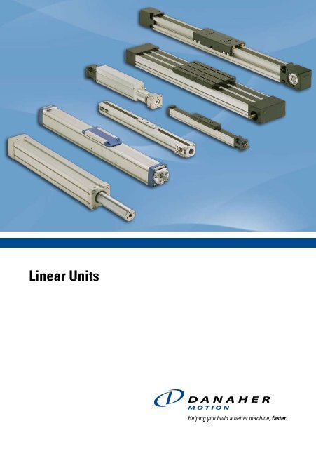
<strong>Linear</strong> <strong>Units</strong>
<strong>Linear</strong> <strong>Units</strong>Table of ContentsIntroduction...................................................................................................... 5Introduction.............................................................................................. 5How to Choose a Unit.........................................................................6 - 7Technical Introduction......................................................................8 - 11<strong>Linear</strong> <strong>Units</strong> with Ball Screw Drive and Ball Guide............................... 13Introduction............................................................................................. 13Overview...........................................................................................14 - 15WM40S..............................................................................................16 - 17WM40D.............................................................................................18 - 19WM60D.............................................................................................20 - 21WM60S..............................................................................................22 - 23WM60X..............................................................................................24 - 25WM80D.............................................................................................26 - 27WM80S..............................................................................................28 - 29WM120D...........................................................................................30 - 31WV60.................................................................................................32 - 33WV80.................................................................................................34 - 35WV120...............................................................................................36 - 37MLSM60D.........................................................................................38 - 39MLSM80D.........................................................................................40 - 412HBE10..............................................................................................42 - 432HBE20..............................................................................................44 - 45<strong>Linear</strong> <strong>Units</strong> with Ball Screw Drive and Slide Guide............................. 47Introduction............................................................................................. 47Overview...........................................................................................48 - 49WB40.................................................................................................50 - 51WB60.................................................................................................52 - 53M55....................................................................................................54 - 55M75....................................................................................................56 - 57M100..................................................................................................58 - 59M75D..................................................................................................60 - 61M100D................................................................................................62 - 63<strong>Linear</strong> <strong>Units</strong> with Belt Drive and Ball Guide............................................ 65Introduction............................................................................................. 65Overview...........................................................................................66 - 67WH40.................................................................................................68 - 69WM60Z..............................................................................................70 - 71WM80Z, standard carriage............................................................72 - 73WM80Z, short carriage..................................................................74 - 75M55....................................................................................................76 - 77M75....................................................................................................78 - 79M100..................................................................................................80 - 81MLSM80Z..........................................................................................82 - 83<strong>Linear</strong> <strong>Units</strong> with Belt Drive and Slide Guide.......................................... 85Introduction............................................................................................. 85Overview...........................................................................................86 - 87M50....................................................................................................88 - 89M55....................................................................................................90 - 91M75 ...................................................................................................92 - 93M100..................................................................................................94 - 95<strong>Linear</strong> <strong>Units</strong> with Belt Drive and Wheel Guide....................................... 97Introduction............................................................................................. 97Overview...........................................................................................98 - 99WH50.............................................................................................100 - 101WH80.............................................................................................102 - 103WH120...........................................................................................104 - 105MLSH60Z.......................................................................................106 - 107MLSH80Z.......................................................................................108 - 109<strong>Linear</strong> Lifting <strong>Units</strong>...................................................................................... 111Introduction........................................................................................... 111Overview...................................................................................... 112 - 113WHZ50...........................................................................................114 - 115WHZ80...........................................................................................116 - 117Z2....................................................................................................118 - 119Z3....................................................................................................120 - 121ZB...................................................................................................122 - 123<strong>Linear</strong> Rod <strong>Units</strong>.......................................................................................... 125Introduction........................................................................................... 125Overview.......................................................................................126 - 127WZ60..............................................................................................128 - 129WZ80..............................................................................................130 - 131T90..................................................................................................132 - 133T130................................................................................................134 - 135Accessories................................................................................................. 137Accessory index................................................................................... 137Mounting Kits...............................................................................138 - 143Cover and Protection Kits..........................................................144 - 146Motors, Gears and Transmission Kits......................................147 - 171Electrical Feedback Devices.....................................................172 - 181Non Driven <strong>Units</strong>.........................................................................182 - 187Dynamic Servo Actuators................................................................... 188Multi Axis System Kits......................................................................... 189Additional Technical Data......................................................................... 191Additional Technical Data Tables.............................................191 - 195Drive Calculations.......................................................................196 - 197Deflection Calculations..............................................................198 - 199Ordering........................................................................................................ 201How to Order......................................................................................... 201Keys for <strong>Units</strong> with Ball Screw and Ball Guides....................202 - 205Keys for <strong>Units</strong> with Ball Screw and Slide Guides..................206 - 208Keys for <strong>Units</strong> with Belt Drive and Ball Guides......................209 - 212Keys for <strong>Units</strong> with Belt Drive and Slide Guides............................. 213Keys for <strong>Units</strong> with Belt Drive and Wheel Guides.................214 - 215Keys for <strong>Linear</strong> Lifting <strong>Units</strong>.......................................................216 - 217Keys for <strong>Linear</strong> Rod <strong>Units</strong>.................................................................... 218Keys for Non Driven <strong>Units</strong>..........................................................219 - 220www.danahermotion.com
www.danahermotion.com
<strong>Linear</strong> <strong>Units</strong>IntroductionDanaher Motions linear units range consists of products from world known brandssuch as Thomson, Neff and Tollo. These three companies have been a part of thelinear unit development elite for decades and are now forming one group of productsoffered to the market under the brand name Danaher Motion. Regardless of yourapplication you can be sure that Danaher Motion can offer you a product to matchyour linear motion needs.NeffThomsonDanaher MotionTolloNeff was founded in 1905 offering products for the linear motionmarket and over the decades Neff has become a market leaderthe ball screw technology. The first linear unit from Neff waspresented in 1981 at the FAMETA show in Stuttgart.Thomson dates back to the 1940s when the first ball bushingbearing in the world was presented to the market. The productporfolio expanded and in the 1980s Thomson built their firstcomplete linear unit.Danaher Motion has now selected the most competitiveproducts from each brand resulting in a state of the art productrange. The range covers the smallest and most compact linearunits to the biggest and most robust. Danaher Motion canmatch your linear motion needs with a wide range of ball screwand belt driven units using a variety of guide technologies,designed to work in harsh environments, at high speeds or inhigh precision systems.Tollo was founded in 1981 and started as a lifting equipmentmanufacturer. The product potfolio grew rapidly and in 1982Tollo presented their first linear unit at the Technical Fair inStockholm.www.danahermotion.com
How to Choose a UnitDanaher Motion offer a wide range of linear units, each designedfor a specific purpose and with its own unique features. Onwww.danahermotion.com/PosSlides_Lin<strong>Units</strong>_advisor you canfind a product advisor that will help you specify the unit you need,and our application engineers will be happy to help you withfurther technical advice.Ball Screw Driven, Ball Guided <strong>Units</strong>VelocityNoiseAccelerationThe diagrams shown here give you a brief overview of the keystrengths of each group.MaintenanceRepeatabilityCostForceGuide Robustness Load TorqueStiffness<strong>Units</strong> designed for high thrust, payload, high precision andstiffness.• Force up to 12000 N• Repeatability down to 0,005mmBall Screw Driven, Slide Guided <strong>Units</strong>Belt Driven, Ball Guided <strong>Units</strong>VelocityVelocityNoiseAccelerationNoiseAccelerationMaintenanceRepeatabilityMaintenanceRepeatabilityCostForceCostForceGuide Robustness Load TorqueStiffnessGuide Robustness Load TorqueStiffnessDesigned for low cost, high thrust operations in demandingenvironments.• Cost efficient units • Washdown protected versions• Durable guide systemSmooth running units for dynamic applications with high speed,high acceleration and high loads requiring a long lifetime.• Speed up to 5 m/s• Acceleration up to 40 m/s 2www.danahermotion.com
<strong>Linear</strong> <strong>Units</strong>Belt Driven, Slide Guided <strong>Units</strong>Belt Driven, Wheel Guided <strong>Units</strong>Velocity VelocityNoiseAccelerationNoiseAccelerationMaintenanceRepeatability MaintenanceRepeatabilityCostForceCostForceGuide Robustness Load TorqueStiffnessGuide Robustness Load TorqueStiffness<strong>Units</strong> for dynamic applications requiring high speed, high acceleration,low maintenance and smooth travel.• Cost efficient guide system• Chemically protected versions<strong>Units</strong> for dynamic applications with high speed, high acceleration,smooth motion and medium to high loads.• Speed up to 10 m/s• Acceleration up to 40 m/s 2<strong>Linear</strong> Lifting <strong>Units</strong><strong>Linear</strong> Rod <strong>Units</strong>Developed for lifting applications<strong>Linear</strong> units with rodTelescopic modelsavailableModels with ballscrew or belt drivePerfect for hydraulicsreplacementHigh accuracyball screw driveLoad up to750 kgHighrepeatabilityLoad up to40 000 NHighrepeatabilitySpeed up to10 m/sStroke up to3000 mmSpeed upto 2 m/sStroke up to2000 mmBall, slide orwheel guided modelsLarge rangeof accessoriesBall or slideguided modelsLarge rangeof accessoriesLoad torqueup to 2000 NmModels withIP65 sealing<strong>Units</strong> for lifting applications. Often used in X-Y configurations incombination with other linear units.<strong>Units</strong> designed for lifting applications or for the replacement ofhydraulic and pneumatic cylinders.www.danahermotion.com
Technical IntroductionBasic <strong>Linear</strong> Unit TerminologyScrew Driven UnitBelt Driven UnitDouble CarriagesRear Bearing HousingSingle CarriageTension StationCover BandProfileDrive shaftFront Bearing HousingT-slot/mounting grooveDrive StationDrive shaftBall Screw DriveA ball screw is made up of a rotating screw and a moving ball nut.The ball nut is attached to the carriage of the unit. It does not have anormal thread, instead balls circulate inside the nut making it work as anefficient ball bearing that travels along the screw. Ball screws come ina large variety of leads, diameters and tolerance classes. The toleranceclass (T3, T5, T7 or T9) indicates the lead tolerance of the screw. Thelower the number, the higher the tolerance. High load capability andhigh accuracy are typical of ball screw driven units.Belt DriveA belt drive consists of a toothed belt which is attached to the carriageof the unit. The belt runs between two pulleys positioned at either endof the profile. One pulley is attached to the motor while the other ismounted in a tensioning station. The belts are made of plastic reinforcedwith steel cords. High speeds, long stroke, low noise and low overallweight are typical features of belt driven units.www.danahermotion.com
<strong>Linear</strong> <strong>Units</strong>Technical IntroductionBall GuidesA ball guide consists of a ball rail and a ball bushing. The ball rail is madeof hardened steel and runs along the inside of the profile. The ball bushingis attached to the carriage of the unit and contains balls that roll againstthe rail. The balls in the bushing can be recirculating or have fixed ballpositions depending on the type of ball guide. The recirculating type has alonger life and better load capability while the fixed type typically is muchsmaller. Danaher Motion uses three major types of ball guides in its linearunits. Either the compact single rail type with recirculating ball bushing(A), the stronger double rail type also with recirculating ball bushings (B)or the fixed ball position ball bushings type (not shown) which requirevery little space and are used in the smallest units. Ball guides offer highaccuracy, high loads and medium speed.Wheel GuidesA wheel guide consists of ball bearing wheels that run on a hardenedsteel rail. Wheel guides are a simple and robust guiding method offeringhigh speeds, high loads and medium accuarcy.AScrew SupportsScrew supports allow screw driven units to travel at high speed evenwhen stroke becomes longer. The supports reduce the unsupportedlength of the screw, that otherwise would be subjected to vibrations.Screw supports come in single (one screw support on each side of thecarriage) or double (two supports on each side) versions. Screw supportunits will have a slightly shorter stroke for a given overall length.BSlide GuidesA slide guide consist of a guide attached to the inside of the profile anda slide bushing attached to the carriage. The guide can be made ofdifferent materials (e.g. polished hardened steel, anodized aluminium)while the bushing is made of a polymer material. There are two typesof bushings, fixed and prism. Prism bushings can move in relation tothe guide which results in longer life and higher load capabilities. Slidebushings are silent, simple, reliable and robust and can be used in dirtyand dusty environments. They are also resistant to shock loads, have along life expectancy and require little or no maintenance.Ball Screw <strong>Units</strong> with Double Ball NutsUsing double ball nuts will increase the repeatability of the unit. Theball nuts are installed so that they are pre-tensioned against each othereleminating the play between the nuts and the screw. A double nut unitwill have a slightly shorter stroke for a given overall length.www.danahermotion.com
Technical IntroductionSingle CarriageSingle carriage units have one carriage. Some linear unit models alsohave the option of long or short single carriage. The long carriage handlehigher loads but will have a longer overall length for a given stroke.Double CarriagesDouble carriage units have two carriages which gives them higher loadcapabilites than single carriage units. When ordering a double carriageunit the distance between the two carriages needs to be defined. Thisdistance is called La or Lc depending on the model.Cover BandCover bands are used on some units to protect then from the ingress offoreign objects through the opening in the profile where the carriageruns. They are made of plastic (A) or stainless steel (B). In the case ofplastic the cover band seals the profile by snapping into small groovesrunning along the carriage opening. In the case of stainless steel thecover band seal the profile magnetically using magnet strips mountedon each side of the carriage opening. Some units equipped with coverbands also have a self-adjusting cover band tensioning mechanism. Thiseleminates any slack in the cover band that can occur from temperaurechanges, thus improving the sealing degree and the expected life of thecover band.Theoretical Stroke and Practical StrokeThe theoretical maximum stroke (S max) is the length that the carriagecan travel from one end of the unit to the other. However, using themaximum stroke means that the carriage will collide with the ends ofthe profile. The practical stroke is therefore shorter. We recommendthat you specify a unit that have at least 100 mm longer stroke than themaximum stroke you need so that the unit can stop before colliding withthe ends and also allow for some adjustment of the unit postition at themounting.A<strong>Units</strong> with Left/right Moving Carriages<strong>Units</strong> with left/right moving carriages have two carriages moving inopposite directions when the drive shaft is rotated. This type of unit hasa ball screw where half of the screw has a left hand thread and the otherhalf a right hand thread.B10 www.danahermotion.com
<strong>Linear</strong> <strong>Units</strong>Technical IntroductionMaintenanceMost units require lubrication. General lubrication requirements can befound in the general specifications table on the product data pages. Thelubrication intervals, grease qualities and specific lubrication instructionscan be found in the installation and service manual of each unit. Noother regular maintenance is needed except for normal cleaning andinspection. <strong>Units</strong> with a cover band may also require irregular cover bandreplacement due to wear. The belt in belt driven units should not requirere-tensioning under normal operating conditions.Mounting PositionMost units can be mounted in any direction. Any restrictions on mountingpositions are shown on the product presentation pages at the beginningof each product category chapter. Even where units may be mounted inany direction there are some considerations. None of the units are selflockingwhich means that a vertical unit will drop the carriage/load if noexternal brake (such as a brake in the motor, etc.) is applied to the driveshaft of the unit. In the case of belt driven units care must be taken as thecarriage/load will drop immediately in the case of a belt breakage. This isparticularly important in vertical applications. All ball screw driven unitsare equipped with a safety nut to prevent the carriage/load being releasedin case of ball breakage.Working EnvironmentAll units are designed for use in normal industrial environments. <strong>Units</strong>which have an open profile (i.e. have no cover band) are more sensitive todust, dirt and fluids. These units require some kind of cover if they are usedin environments where dust, dirt or fluids are present. Optional bellows/shrouds are available for some of our open profile units. Enhanced washdownor chemical protection can be ordered for our closed profile units.Please refer to the accessory pages. In all cases where a unit will beexposed to aggressive chemicals, heavy vibrations or other potentiallyharmful processes we recommend that you contact us for further advice.Duty CycleAll units are designed for a 100% duty cycle. However, where the unitruns at extreme load, speed, acceleration and temperature or for longoperating periods the expected life time may be reduced.Operation and Storage TemperatureOperational temperature limits can be found in the performance tableson the product data pages. <strong>Units</strong> can be stored or transported within thesame temperature range. Please contact us if the unit will be exposedto higher/lower temperatures than recommended during storage ortransportationLoad and Load Torque ValuesFor some units the load and load torque values are given for both the completeunit and the guiding system. The values for the complete unit arethe values under which the unit can operate. The values for the guidingsystem should only be used when comparing different units and do notdescribe the actual performance of the complete unit.Deflection of the ProfileSome units require support along the whole profile whilst some areself supporting over a specified span. Further details can be found onthe product data pages. The recommended support intervals shouldbe followed to minimise deflection of the unit. The maximum distancebetween the support points is shown on the product data pages. Thedeflection of the unit can also be calculated using the information in theAdditional data and calculations chapter.Lifetime ExpectancyWhen determining the lifetime for a linear unit it is necessary to evaluateall forces and moments that are acting on the unit. The data and formulasgiven in this catalogue serve as a basis for this. For a more detailed lifetimecalculation please use our sizing and selection software. Please contactus for further guidance.End of Stroke Limit SwitchesIf a unit runs at speed to the ends of its stroke there is a risk of damage.Damage can be prevented by using end of stroke limit switches to detectand engage a brake and/or cut power to the motor when the unit nears theend of the unit. You must ensure that there is sufficient distance betweenthe end of stroke limit switch and the end of the unit, to allow the carriageto come to a complete stop before colliding with the end. The requiredstopping distance depends on the speed and the load and will have to becalculated for each application. The stopping distance must be taken intoaccount when defining the necessary stroke.Position FeedbackThe position of the carriage/rod/lifting profile can be obtained in manyways. The most common way is to equip the unit with an encoder or touse a motor which has a built in feed back device (encoder, resolver, etc.).To many units there are encoders or/and encoder mounting kits available.See the accessory chapter.Packages and Multi Axis KitsDanaher Motion can offer complete pre-defined packages (linear unit,gear and servo motor assembled and shipped with servo drive and cables)as well as mounting kits for the creation of two and three axis systemsPlease contact us for further information.www.danahermotion.com11
12 www.danahermotion.com
<strong>Linear</strong> <strong>Units</strong><strong>Linear</strong> <strong>Units</strong> with Ball Screw Drive and Ball GuidePowerLine, ForceLine, Microstage, AccuSlideVelocityNoiseAccelerationMaintenanceRepeatabilityCostForceGuide RobustnessLoad TorqueStiffnessTypical ApplicationsTypical applications are where high accuracy and load capability is required butwhere speed is less important. Typical examples are machining operations and inthe handling of heavy goods that need accurate positioning.www.danahermotion.com13
PowerLine WMWM40Features• Can be installed in all directions• Patented guide system• Patented self-adjusting plastic cover band• Patented screw support systemParameter WM40S WM40D WM60D WM60S WM60X WM80D WM80S WM120DProfile size (width × height) [mm] 40 × 40 40 × 40 60 × 60 60 × 60 60 × 60 80 × 80 80 × 80 120 × 120Stroke length (S max), maximum [mm] 2000 2000 11000 5000 10340 11000 5000 11000<strong>Linear</strong> speed, maximum [m/s] 0,25 0,25 2,5 2,5 0,25 2,5 2,5 2,0Dynamic carriage load (Fz), maximum [N] 600 600 2000 1400 2000 3000 2100 6000Remarkssingle ballnutdouble ballnutsdouble ballnutssingle ballnutleft/rightscrewdouble ballnutssingle ballnutdouble ballnutsPage 16 18 20 22 24 26 28 30PowerLine WVWV80Features• Can be installed in all directions• Patented self-adjusting plastic cover band• Patented screw support system• The units require external guidesParameter WV60 WV80 WV120Profile size (width × height) [mm] 60 × 60 80 × 80 120 × 120Stroke length (S max), maximum [mm] 11000 11000 11000<strong>Linear</strong> speed, maximum [m/s] 2,5 2,5 2,0Dynamic carriage load (Fz), maximum [N] - - -Remarksdouble ball nutsthe units has no guidesdouble ball nutsthe units has no guidesdouble ball nutsthe units has no guidesPage 32 34 36ForceLine MLSMMLSM80DFeatures• Can be installed in all directions• Patented guide system• Patented plastic cover band• Patented screw support systemParameter MLSM60D MLSM80DProfile size (width × height) [mm] 160 × 65 240 × 85Stroke length (S max), maximum [mm] 5500 5200<strong>Linear</strong> speed, maximum [m/s] 2,5 2,0Dynamic carriage load (Fz), maximum [N] 6000 8000Remarks double ball nuts double ball nutsPage 38 4014 www.danahermotion.com
<strong>Linear</strong> <strong>Units</strong>AccuSlide 2HBE2HBE20Features• Can be installed in all directions• High load capablities• Low profile height• Play free ball screw offer high repeatabilityParameter 2HBE10 2HBE20Profile size (width × height) [mm] 100× 33,5 200 × 44Stroke length (S max), maximum [mm] 850 2800<strong>Linear</strong> speed, maximum [m/s] 0,5 1,3Dynamic carriage load (Fz), maximum [N] 8250 38000Remarksno cover band, bellows or shrouds optionavailableno cover band, bellows or shrouds optionavailablePage 42 44WM-Series Technical PresentationScrew supportPatented screw support systempermits high speed at long strokelengths while reducing the strokewith a minimum.Double ball nutsDouble pre-tensioned ball nutsimprove the accuracy and allowsre-tensioning increasing thelifetime of the unit.Central lubricationOne central lubrication point onthe carriage services the entireunit resulting in a minimummaintenace required.Ball guidesIntegrated patented ball guideswith hardened steel tracks foroptimum performance.www.danahermotion.comBall cagesThe balls in the ball guides areprotected by a ball cage whichensures a long life.Cover bandThe patented self-adjustingcover band protect the unit fromthe penetration of dirt, dust andliquids.15
WM40SBall Screw Drive, Ball Guide, Single Ball Nut» Ordering key - see page 202» Accessories - see page 137» Additional data - see page 191General SpecificationsCarriage Idle Torque (M idle) [Nm]ParameterWM40SProfile size (w × h) [mm] 40 × 40Input speed [rpm]Screw lead [mm]p = 5Type of screwCarriage sealing systemScrew supportsLubricationIncluded accessoriesball screw with single nutself-adjusting plastic cover bandincluded in all units that requirescrew supportscentral lubrication of all parts thatrequire lubrication4 × mounting clamps150 0,31500 0,53000 0,8M idle = the input torque needed to move the carriage with no load on it.Deflection of the ProfilePerformance SpecificationsParameterWM40SStroke length (S max), maximum [mm] 2000<strong>Linear</strong> speed, maximum [m/s] 0,25Acceleration, maximum [m/s 2 ] 20Repeatability [± mm] 0,02Input speed, maximum [rpm] 3000A mounting clamp must be installed at least at every 750 mm to be able to operate themaximum load. Less clamps may be required if less load is being operated, see the additionaltechnical data for more information.Critical SpeedOperation temperature limits [°C] 0 – 80Dynamic load (Fx), maximum [N] 1000Dynamic load (Fy), maximum [N] 450 1 / 5300 2Dynamic load (Fz), maximum [N] 600 1 / 6790 2Dynamic load torque (Mx), maximum [Nm] 10 1 / 30 2Dynamic load torque (My), maximum [Nm] 30 1 / 230 2Dynamic load torque (Mz), maximum [Nm] 30 1 / 230 2Drive shaft force (Frd), maximum [N] 100Drive shaft torque (Mta), maximum [Nm] 3Definition of ForcesBall screw diameter (d0) [mm] 12Ball screw lead (p) [mm] 5Weightof unit with zero strokeof every 100 mm of strokeof each carriage1Value for the complete unit2Value for the ball guide only[kg]1,500,300,3616 www.danahermotion.com
<strong>Linear</strong> <strong>Units</strong>WM40SBall Screw Drive, Ball Guide, Single Ball NutA1: depth 7A2: lubricating nipple on both sides DIN3405 D 1/AStroke length (S max) [mm] A [mm] B [mm] C [mm]0 – 500 (0 – 450) 65 35 270 (320)501 – 1100 (451 – 1050) 65 45 280 (330)1101 – 2000 (1051 – 1950) 70 60 300 (350)Values between brackets = for units with long carriageA3: socket cap screw ISO4762-M5×12 8.8A4: ENF inductive sensor rail option kit (optional)Double CarriagesParameterWM40SMinimum distance between carriages (L A) [mm] 175Dynamic load (Fy), maximum [N] 900Dynamic load (Fz), maximum [N] 1200Dynamic load torque (My), maximum [Nm] L A 1 × 0,45Dynamic load torque (Mz), maximum [Nm] L A 1 × 0,6Force required to move second carriage [N] 40Total length (L tot) [mm] S max + C + L A1Value in mmwww.danahermotion.com17
WM40DBall Screw Drive, Ball Guide, Double Ball Nuts, Long Carriage» Ordering key - see page 202» Accessories - see page 137» Additional data - see page 191General SpecificationsCarriage Idle Torque (M idle) [Nm]ParameterWM40DProfile size (w × h) [mm] 40 × 40Input speed [rpm]Screw lead [mm]p = 5Type of screwCarriage sealing systemScrew supportsLubricationIncluded accessoriesball screw with double nutsself-adjusting plastic cover bandincluded in all units that requirescrew supportscentral lubrication of all parts thatrequire lubrication4 × mounting clamps150 0,41500 0,63000 0,9M idle = the input torque needed to move the carriage with no load on it.Deflection of the ProfilePerformance SpecificationsParameterWM40DStroke length (S max), maximum [mm] 1950<strong>Linear</strong> speed, maximum [m/s] 0,25Acceleration, maximum [m/s 2 ] 20Repeatability [± mm] 0,01Input speed, maximum [rpm] 3000A mounting clamp must be installed at least at every 750 mm to be able to operate themaximum load. Less clamps may be required if less load is being operated, see the additionaltechnical data for more information.Critical SpeedOperation temperature limits [°C] 0 – 80Dynamic load (Fx), maximum [N] 1000Dynamic load (Fy), maximum [N] 450 1 / 5300 2Dynamic load (Fz), maximum [N] 600 1 / 6790 2Dynamic load torque (Mx), maximum [Nm] 10 1 / 30 2Dynamic load torque (My), maximum [Nm] 30 1 / 230 2Dynamic load torque (Mz), maximum [Nm] 30 1 / 230 2Drive shaft force (Frd), maximum [N] 100Drive shaft torque (Mta), maximum [Nm] 3Definition of ForcesBall screw diameter (d0) [mm] 12Ball screw lead (p) [mm] 5Weightof unit with zero strokeof every 100 mm of strokeof each carriage1Value for the complete unit2Value for the ball guide only[kg]1,900,300,6018 www.danahermotion.com
<strong>Linear</strong> <strong>Units</strong>WM40DBall Screw Drive, Ball Guide, Double Ball Nuts, Long CarriageA1: depth 6A2: lubricating nipple on both sides DIN3405 D 1/AA3: socket cap screw ISO4762-M5×12 8.8A4: ENF inductive sensor rail option kit (optional)Stroke length (S max) [mm] A [mm] B [mm] C [mm]0 – 500 65 35 320501 – 1100 65 45 3301101 – 2000 70 60 350Double Long CarriagesParameterWM40DMinimum distance between carriages (L A) [mm] 225Dynamic load (Fy), maximum [N] 900Dynamic load (Fz), maximum [N] 1200Dynamic load torque (My), maximum [Nm] L A 1 × 0,45Dynamic load torque (Mz), maximum [Nm] L A 1 × 0,6Force required to move second carriage [N] 40Total length (L tot) [mm] S max + C + L A1Value in mmwww.danahermotion.com19
WM60DBall Screw Drive, Ball Guide, Double Ball Nuts» Ordering key - see page 202» Accessories - see page 137» Additional data - see page 191General SpecificationsCarriage Idle Torque (M idle) [Nm]ParameterWM60DProfile size (w × h) [mm] 60 × 60Input speed [rpm]Screw lead [mm]p = 5 p = 20 p = 50Type of screwCarriage sealing systemScrew supportsLubricationIncluded accessoriesball screw with double nutself-adjusting plastic cover bandincluded in all units that requirescrew supportscentral lubrication of all parts thatrequire lubrication4 × mounting clamps150 0,8 1,3 1,61500 1,4 2,0 2,43000 1,8 2,3 2,6M idle = the input torque needed to move the carriage with no load on it.Deflection of the ProfilePerformance SpecificationsParameterWM60DStroke length (S max), maximumscrew lead 5, 20 mmscrew lead 50 mm[mm]110005000<strong>Linear</strong> speed, maximum [m/s] 2,5Acceleration, maximum [m/s 2 ] 20Repeatability [± mm] 0,01Input speed, maximum [rpm] 3000A mounting clamp must be installed at least at every 750 mm to be able to operate themaximum load. Less clamps may be required if less load is being operated, see the additionaltechnical data for more information. <strong>Units</strong> with a profile length over 6300 mm consists of twoprofiles where the joint between the two profiles must be addequately supported on bothsides.Definition of ForcesOperation temperature limits [°C] 0 – 80Dynamic load (Fx), maximum [N] 4000Dynamic load (Fy), maximum [N] 2000 1 / 45980 2Dynamic load (Fz), maximum [N] 2000 1 / 42320 2Dynamic load torque (Mx), maximum [Nm] 100 1 / 740 2Dynamic load torque (My), maximum [Nm] 200 1 / 2990 2Dynamic load torque (Mz), maximum [Nm] 200 1 / 3250 2Drive shaft force (Frd), maximum [N] 500Drive shaft torque (Mta), maximum [Nm] 35Ball screw diameter (d0) [mm] 20Ball screw lead (p) [mm] 5, 20, 50Weightof unit with zero strokeof every 100 mm of strokeof each carriage1Value for the complete unit2Value for the ball guide only[kg]6,160,651,9920 www.danahermotion.com
<strong>Linear</strong> <strong>Units</strong>WM60DBall Screw Drive, Ball Guide, Double Ball NutsA1: depth 11A2: socket cap screw ISO4762-M6×20 8.8A3: ENF inductive sensor rail option kit (optional)Stroke length (S max) [mm] A [mm] B [mm] C [mm]0 - 695 (0 - 505) 115 65 460 (650)696 - 1335 (506 - 1145) 165 115 560 (750)1336 - 2075 (1146 - 1885) 185 135 600 (790)2076 - 2780 (1886 - 2590) 210 160 650 (840)Values between brackets = for units with long carriageA4: tapered lubricating nipple to DIN71412 AM6 on fixed-bearing side as standard featureA5: can be changed over to one of the three alternative lubricating points by the customerStroke length (S max) [mm] A [mm] B [mm] C [mm]2781 - 3545 (2591 - 3355) 230 180 690 (880)3546 - 4285 (3366 - 4095) 250 200 730 (920)4286 - 5015 (4096 - 4825) 275 225 780 (970)5016 - 11000 (4826 - 10810) contact customer serviceLong CarriageParameterWM60DCarriage length [mm] 450Dynamic load torque (My), maximum [Nm] 500Dynamic load torque (Mz), maximum [Nm] 500Weight [kg] 3,1A1: depth 11Double CarriagesParameterWM60DMinimum distance between carriages (L A) [mm] 335Dynamic load (Fy), maximum [N] 4000Dynamic load (Fz), maximum [N] 4000Dynamic load torque (My), maximum [Nm] L A 1 × 2Dynamic load torque (Mz), maximum [Nm] L A 1 × 2Force required to move second carriage [N] 200Total length (L tot) [mm] S max + C + L A1Value in mmwww.danahermotion.com21
WM60SBall Screw Drive, Ball Guide, Single Ball Nut, Short Carriage» Ordering key - see page 202» Accessories - see page 137» Additional data - see page 191General SpecificationsCarriage Idle Torque (M idle) [Nm]ParameterWM60SProfile size (w × h) [mm] 60 × 60Input speed [rpm]Screw lead [mm]p = 5 p = 20 p = 50Type of screwCarriage sealing systemScrew supportsLubricationIncluded accessoriesball screw with single nutself-adjusting plastic cover bandincluded in all units that requirescrew supportscentral lubrication of all parts thatrequire lubrication4 × mounting clamps150 0,7 1,0 1,41500 1,1 1,6 2,03000 1,5 1,8 2,2M idle = the input torque needed to move the carriage with no load on it.Deflection of the ProfilePerformance SpecificationsParameterWM60SStroke length (S max), maximum [mm] 5000<strong>Linear</strong> speed, maximum [m/s] 2,5Acceleration, maximum [m/s 2 ] 10Repeatability [± mm] 0,02Input speed, maximum [rpm] 3000A mounting clamp must be installed at least at every 750 mm to be able to operate themaximum load. Less clamps may be required if less load is being operated, see the additionaltechnical data for more information.Definition of ForcesOperation temperature limits [°C] 0 – 80Dynamic load (Fx), maximum [N] 2800Dynamic load (Fy), maximum [N] 1400 1 / 25920 2Dynamic load (Fz), maximum [N] 1400 1 / 23860 2Dynamic load torque (Mx), maximum [Nm] 50 1 / 410 2Dynamic load torque (My), maximum [Nm] 100 1 / 320 2Dynamic load torque (Mz), maximum [Nm] 100 1 / 320 2Drive shaft force (Frd), maximum [N] 500Drive shaft torque (Mta), maximum [Nm] 35Ball screw diameter (d0) [mm] 20Ball screw lead (p) [mm] 5, 20, 50Weightof unit with zero strokeof every 100 mm of strokeof each carriage1Value for the complete unit2Value for the ball guide only[kg]3,800,651,0022 www.danahermotion.com
<strong>Linear</strong> <strong>Units</strong>WM60SBall Screw Drive, Ball Guide, Single Ball Nut, Short CarriageA1: depth 11A2: socket cap screw ISO4762-M6×20 8.8A3: ENF inductive sensor rail option kit (optional)Stroke length (S max) [mm] A [mm] B [mm] C [mm]0 - 580 95 20 335581 - 1140 110 60 3901141 - 1805 130 80 4301806 - 2460 155 105 480A4: tapered lubricating nipple to DIN71412 AM6 on fixed-bearing side as standard featureA5: can be changed over to one of the three alternative lubricating points by the customerStroke length (S max) [mm] A [mm] B [mm] C [mm]2461 - 3125 175 125 5203126 - 3780 200 150 5703781 - 4445 220 170 6104446 - 5000 240 190 650Double Short CarriagesParameterWM60SMinimum distance between carriages (L A) [mm] 255Dynamic load (Fy), maximum [N] 2800Dynamic load (Fz), maximum [N] 2800Dynamic load torque (My), maximum [Nm] L A 1 × 1,4Dynamic load torque (Mz), maximum [Nm] L A 1 × 1,4Force required to move second carriage [N] 180Total length (L tot) [mm] S max + C + L A1Value in mmwww.danahermotion.com23
WM60XBall Screw Drive, Ball Guide, Left/right Moving Carriages» Ordering key - see page 202» Accessories - see page 137» Additional data - see page 191General SpecificationsCarriage Idle Torque (M idle) [Nm]ParameterWM60XProfile size (w × h) [mm] 60 × 60Input speed [rpm]Screw lead [mm]p = 5Type of screwCarriage sealing systemScrew supportsLubricationIncluded accessoriesball screw with double nutself-adjusting plastic cover bandincluded in all units that requirescrew supportscentral lubrication of all parts thatrequire lubrication4 × mounting clamps150 1,61500 2,83000 3,6M idle = the input torque needed to move the carriage with no load on it.Deflection of the ProfilePerformance SpecificationsParameterWM60XStroke length (S max), maximum [mm] 10340<strong>Linear</strong> speed, maximum [m/s] 0,25Acceleration, maximum [m/s 2 ] 20Repeatability [± mm] 0,01Input speed, maximum [rpm] 3000Operation temperature limits [°C] 0 – 80A mounting clamp must be installed at least at every 750 mm to be able to operate themaximum load. Less clamps may be required if less load is being operated, see the additionaltechnical data for more information. <strong>Units</strong> with a profile length over 5400 mm consists of twoprofiles where the joint between the two profiles must be addequately supported on bothsides.Definition of ForcesDynamic load (Fx), maximum [N] 4000Dynamic load (Fy), maximum [N] 2000 1 / 45980 2Dynamic load (Fz), maximum [N] 2000 1 / 42320 2Dynamic load torque (Mx), maximum [Nm] 100 1 / 740 2Dynamic load torque (My), maximum [Nm] 200 1 / 2990 2Dynamic load torque (Mz), maximum [Nm] 200 1 / 3250 2Drive shaft force (Frd), maximum [N] 500Drive shaft torque (Mta), maximum [Nm] 35Ball screw diameter (d0) [mm] 20Ball screw lead (p) [mm] 5Weightof unit with zero strokeof every 100 mm of strokeof each carriage1Value for the complete unit2Value for the ball guide only[kg]10,330,651,9924 www.danahermotion.com
<strong>Linear</strong> <strong>Units</strong>WM60XBall Screw Drive, Ball Guide, Left/right Moving CarriagesA1: depth 11A2: socket cap screw ISO4762-M6×20 8.8A3: ENF inductive sensor rail option kit (optional)A4: tapered lubricating nipple to DIN71412 AM6 on fixed-bearing side as standard featureA5: can be changed over to one of the three alternative lubricating points by the customerStroke length (S max) [mm] A [mm] B [mm] C [mm] X [mm] Y [mm] Z [mm]0 - 1390 (0 - 1200) 115 65 60 80 620 8001391 - 2670 (1201 - 2480) 165 115 210 230 770 10502671 - 4150 (2481 - 3960) 185 135 250 270 810 11304151 - 5560 (3961 - 5370) 210 160 300 320 860 12305561 - 10340 (5371 - 10150) contact customer seviceValues between brackets = for units with long carriageLong CarriageParameterWM60XCarriage length [mm] 450Dynamic load torque (My), maximum [Nm] 500Dynamic load torque (Mz), maximum [Nm] 500Weight [kg] 3,1A1: depth 11www.danahermotion.com25
WM80DBall Screw Drive, Ball Guide, Double Ball Nuts» Ordering key - see page 202» Accessories - see page 137» Additional data - see page 191General SpecificationsCarriage Idle Torque (M idle) [Nm]ParameterWM80DProfile size (w × h) [mm] 80 × 80Input speed [rpm]Screw lead [mm]p = 5 p = 10 p = 20 p = 50Type of screwCarriage sealing systemScrew supportsLubricationIncluded accessoriesball screw with double nutsself-adjusting plastic cover bandincluded in all units that requirescrew supportscentral lubrication of all parts thatrequire lubrication4 × mounting clamps150 1,1 1,5 1,8 2,31500 1,7 2.1 2,3 3,03000 2,1 2,5 2,6 3,6M idle = the input torque needed to move the carriage with no load on it.Deflection of the ProfilePerformance SpecificationsParameterWM80DStroke length (S max), maximumscrew lead 5, 10, 20 mmscrew lead 50 mm[mm]110005000<strong>Linear</strong> speed, maximum [m/s] 2,5Acceleration, maximum [m/s 2 ] 20Repeatability [± mm] 0,01Input speed, maximum [rpm] 3000A mounting clamp must be installed at least at every 750 mm to be able to operate themaximum load. Less clamps may be required if less load is being operated, see the additionaltechnical data for more information. <strong>Units</strong> with a profile length over 6300 mm consists of twoprofiles where the joint between the two profiles must be addequately supported on bothsides.Definition of ForcesOperation temperature limits [°C] 0 – 80Dynamic load (Fx), maximum [N] 5000Dynamic load (Fy), maximum [N] 3000 1 / 57420 2Dynamic load (Fz), maximum [N] 3000 1 / 54950 2Dynamic load torque (Mx), maximum [Nm] 350 1 / 1360 2Dynamic load torque (My), maximum [Nm] 300 1 / 4230 2Dynamic load torque (Mz), maximum [Nm] 300 1 / 4220 2Drive shaft force (Frd), maximum [N] 700Drive shaft torque (Mta), maximum [Nm] 55Ball screw diameter (d0) [mm] 25Ball screw lead (p) [mm] 5, 10, 20, 50Weightof unit with zero strokeof every 100 mm of strokeof each carriage1Value for the complete unit2Value for the ball guide only[kg]11,571,084,2626 www.danahermotion.com
<strong>Linear</strong> <strong>Units</strong>WM80DBall Screw Drive, Ball Guide, Double Ball NutsA1: depth 12 mmA2: socket cap screw ISO4762-M6×20 8.8A3: ENF inductive sensor rail option kit (optional)Stroke length (S max) [mm] A [mm] B [mm] C [mm]0 - 780 (0 - 610) 120 80 500 (670)781 - 1535 (611 - 1365) 170 125 595 (765)1536 - 2375 (1366 - 2205) 190 145 635 (805)2376 - 3205 (2206 - 3035) 215 170 685 (855)Values between brackets = for units with long carriageA4: tapered lubricating nipple to DIN71412 AM6 on fixed-bearing side as standard featureA5: can be changed over to one of three alternative lubrication points by customerStroke length (S max) [mm] A [mm] B [mm] C [mm]3206 - 4045 (3036 - 3875) 235 190 725 (895)4046 - 4885 (3876 - 4715) 255 210 765 (935)4886 - 5000 (4716 - 4830) 280 235 815 (985)5001 - 11000 (4717 - 10830) contact customer serviceLong CarriageParameterWM80DCarriage length [mm] 450Dynamic load torque (My), maximum [Nm] 750Dynamic load torque (Mz), maximum [Nm] 750Weight [kg] 6,4A1: depth 12 mmDouble CarriagesParameterWM80DMinimum distance between carriages (L A) [mm] 360Dynamic load (Fy), maximum [N] 6000Dynamic load (Fz), maximum [N] 6000Dynamic load torque (My), maximum [Nm] L A 1 × 3Dynamic load torque (Mz), maximum [Nm] L A 1 × 3Force required to move second carriage [N] 250Total length (L tot) [mm] S max + C + L A1Value in mmwww.danahermotion.com27
WM80SBall Screw Drive, Ball Guide, Singel Ball Nut, Short Carriage» Ordering key - see page 202» Accessories - see page 137» Additional data - see page 191General SpecificationsCarriage Idle Torque (M idle) [Nm]ParameterWM80SProfile size (w × h) [mm] 80 × 80Input speed [rpm]Screw lead [mm]p = 5 p = 10 p = 20 p = 50Type of screwCarriage sealing systemScrew supportsLubricationIncluded accessoriesball screw with single nutself-adjusting plastic cover bandincluded in all units that requirescrew supportscentral lubrication of all parts thatrequire lubrication4 × mounting clamps150 0,9 1,1 1,3 2,01500 1,3 1,5 1,8 2,43000 1,7 1,8 2,0 2,9M idle = the input torque needed to move the carriage with no load on it.Deflection of the ProfilePerformance SpecificationsParameterWM80SStroke length (S max), maximum [mm] 5000<strong>Linear</strong> speed, maximum [m/s] 2,5Acceleration, maximum [m/s 2 ] 20Repeatability [± mm] 0,02Input speed, maximum [rpm] 3000A mounting clamp must be installed at least at every 750 mm to be able to operate themaximum load. Less clamps may be required if less load is being operated, see the additionaltechnical data for more information.Definition of ForcesOperation temperature limits [°C] 0 – 80Dynamic load (Fx), maximum [N] 3500Dynamic load (Fy), maximum [N] 2100 1 / 37440 2Dynamic load (Fz), maximum [N] 2100 1 / 35830 2Dynamic load torque (Mx), maximum [Nm] 150 1 / 890 2Dynamic load torque (My), maximum [Nm] 180 1 / 580 2Dynamic load torque (Mz), maximum [Nm] 180 1 / 600 2Drive shaft force (Frd), maximum [N] 700Drive shaft torque (Mta), maximum [Nm] 55Ball screw diameter (d0) [mm] 25Ball screw lead (p) [mm] 5, 10, 20, 50Weightof unit with zero strokeof every 100 mm of strokeof each carriage1Value for the complete unit2Value for the ball guide only[kg]7,01,11,628 www.danahermotion.com
<strong>Linear</strong> <strong>Units</strong>WM80SBall Screw Drive, Ball Guide, Singel Ball Nut, Short CarriageA1: depth 12 mmA2: socket cap screw ISO4762-M6×20 8.8A3: ENF inductive sensor rail option kit (optional)Stroke length (S max) [mm] A [mm] B [mm] C [mm]0 - 680 95 35 350681 - 1310 125 80 4251311 - 2065 150 105 4752066 - 2830 170 125 515A4: tapered lubricating nipple to DIN71412 AM6 on fixed-bearing side as standard featureA5: can be changed over to one of three alternative lubrication points by customerStroke length (S max) [mm] A [mm] B [mm] C [mm]2831 - 3590 195 150 5653591 - 4355 215 170 6054356 - 5000 235 190 645Double CarriagesParameterWM80SMinimum distance between carriages (L A) [mm] 280Dynamic load (Fy), maximum [N] 4200Dynamic load (Fz), maximum [N] 4200Dynamic load torque (My), maximum [Nm] L A 1 × 2,1Dynamic load torque (Mz), maximum [Nm] L A 1 × 2,1Force required to move second carriage [N] 225Total length (L tot) [mm] S max + C + L A1Value in mmwww.danahermotion.com29
WM120DBall Screw Drive, Ball Guide, Double Ball Nuts» Ordering key - see page 202» Accessories - see page 137» Additional data - see page 191General SpecificationsCarriage Idle Torque (M idle) [Nm]ParameterWM120DProfile size (w × h) [mm] 120 × 120Input speed [rpm]Screw lead [mm]p = 5 p = 10 p = 20 p = 40Type of screwCarriage sealing systemScrew supportsLubricationIncluded accessoriesball screw with double nutsself-adjusting plastic cover bandincluded in all units that requirescrew supportscentral lubrication of all parts thatrequire lubrication4 × mounting clamps150 1,4 2,0 2,3 2,41500 2,5 3,0 3,3 3,83000 3,0 3,7 4,0 4,3M idle = the input torque needed to move the carriage with no load on it.Deflection of the ProfilePerformance SpecificationsParameterWM120DStroke length (S max), maximumscrew lead 5, 10, 20 mmscrew lead 40 mm[mm]110005000<strong>Linear</strong> speed, maximum [m/s] 2,0Acceleration, maximum [m/s 2 ] 20Repeatability [± mm] 0,01Input speed, maximum [rpm] 3000A mounting clamp must be installed at least at every 750 mm to be able to operate themaximum load. Less clamps may be required if less load is being operated, see the additionaltechnical data for more information. <strong>Units</strong> with a profile length over 5400 mm consists of twoprofiles where the joint between the two profiles must be addequately supported on bothsides.Definition of ForcesOperation temperature limits [°C] 0 – 80Dynamic load (Fx), maximumscrew lead 5, 10, 20 mmscrew lead 40 mm[N]120008000Dynamic load (Fy), maximum [N] 6000 1 / 74890 2Dynamic load (Fz), maximum [N] 6000 1 / 71670 2Dynamic load torque (Mx), maximum [Nm] 500 1 / 2890 2Dynamic load torque (My), maximum [Nm] 600 1 / 6660 2Dynamic load torque (Mz), maximum [Nm] 600 1 / 6960 2Drive shaft force (Frd), maximum [N] 1000Drive shaft torque (Mta), maximum [Nm] 80Ball screw diameter (d0) [mm] 32Ball screw lead (p) [mm] 5, 10, 20, 40Weightof unit with zero strokeof every 100 mm of strokeof each carriage1Value for the complete unit2Value for the ball guide only[kg]25,911,939,2530 www.danahermotion.com
<strong>Linear</strong> <strong>Units</strong>WM120DBall Screw Drive, Ball Guide, Double Ball NutsA1: depth 22A2: socket cap screw ISO4762-M8×20 8.8Stroke length (S max) [mm] A [mm] B [mm] C [mm]0 - 890 (0 - 710) 155 100 595 (775)891 - 1695 (711 - 1515) 225 170 735 (815)1696 - 2625 (1516 - 2445) 260 205 805 (985)2626 - 3555 (2446 - 3375) 295 240 875 (1055)Values between brackets = for units with long carriageA3: tapered lubricating nipple to DIN71412 M8×1 on fixed-bearing side as standard featureA4: can be changed over to one of the three alternative lubricating points by the customerStroke length (S max) [mm] A [mm] B [mm] C [mm]3556 - 4485 (3376 - 4305) 330 275 945 (1125)4486 - 5000 (4306 - 4820) 365 310 1015 (1195)5001 - 11000 (4307 - 10820) contact customer serviceLong CarriageParameterWM120DCarriage length [mm] 500Dynamic load torque (My), maximum [Nm] 1500Dynamic load torque (Mz), maximum [Nm] 1500Weight [kg] 14,2A1: depth 22Double CarriagesParameterWM120DMinimum distance between carriages (L A) [mm] 450Dynamic load (Fy), maximum [N] 12000Dynamic load (Fz), maximum [N] 12000Dynamic load torque (My), maximum [Nm] L A 1 × 6Dynamic load torque (Mz), maximum [Nm] L A 1 × 6Force required to move second carriage [N] 300Total length (L tot) [mm] S max + C + L A1Value in mmwww.danahermotion.com31
WV60Ball Screw Drive, No Guides» Ordering key - see page 203» Accessories - see page 137» Additional data - see page 191General SpecificationsCarriage Idle Torque (M idle) [Nm]ParameterWV60Profile size (w × h) [mm] 60 × 60Input speed [rpm]Screw lead [mm]p = 5 p = 20 p = 50Type of screwCarriage sealing systemScrew supportsLubricationIncluded accessoriesball screw with double nutself-adjusting plastic cover bandincluded in all units that requirescrew supportscentral lubrication of all parts thatrequire lubrication4 × mounting clamps150 0,7 0,9 1,11500 1,3 1,5 1,53000 1,7 1,9 2,1M idle = the input torque needed to move the carriage with no load on it.Deflection of the ProfilePerformance SpecificationsParameterWV60Stroke length (S max), maximumscrew lead 5, 20 mmscrew lead 50 mm[mm]110005000<strong>Linear</strong> speed, maximum [m/s] 2,5Acceleration, maximum [m/s 2 ] 20Repeatability [± mm] 0,01Input speed, maximum [rpm] 3000A mounting clamp must be installed at least at every 750 mm to be able to operate themaximum load. Less clamps may be required if less load is being operated, see the additionaltechnical data for more information. <strong>Units</strong> with a profile length over 6300 mm consists of twoprofiles where the joint between the two profiles must be addequately supported on bothsides.Definition of ForcesOperation temperature limits [°C] 0 – 80Dynamic load (Fx), maximum [N] 4000Dynamic load (Fy), maximum [N] 0Dynamic load (Fz), maximum [N] 0Dynamic load torque (Mx), maximum [Nm] 0Dynamic load torque (My), maximum [Nm] 0Dynamic load torque (Mz), maximum [Nm] 0Drive shaft force (Frd), maximum [N] 500Drive shaft torque (Mta), maximum [Nm] 35Ball screw diameter (d0) [mm] 20Ball screw lead (p) [mm] 5, 20, 50Weightof unit with zero strokeof every 100 mm of strokeof each carriage[kg]4,720,551,4232 www.danahermotion.com
<strong>Linear</strong> <strong>Units</strong>WV60Ball Screw Drive, No GuidesA1: depth 11A2: socket cap screw ISO4762-M6×20 8.8A3: ENF inductive sensor rail option kit (optional)Stroke length (S max) [mm] A [mm] B [mm] C [mm]0 - 690 130 80 430691 - 1415 155 105 4801416 - 2155 175 125 5202156 - 2885 200 150 570A4: tapered lubricating nipple to DIN71412 AM6 on fixed-bearing side as standard featureA5: can be changed over to one of the three alternative lubricating points by the customerStroke length (S max) [mm] A [mm] B [mm] C [mm]2886 - 3625 220 170 6103626 - 4355 245 195 6604256 - 5095 265 215 7005096 - 11000 contact customer servicewww.danahermotion.com33
WV80Ball Screw Drive, No Guides» Ordering key - see page 203» Accessories - see page 137» Additional data - see page 191General SpecificationsCarriage Idle Torque (M idle) [Nm]ParameterWV80Profile size (w × h) [mm] 80 × 80Input speed [rpm]Screw lead [mm]p = 5 p = 10 p = 20 p = 50Type of screwCarriage sealing systemScrew supportsLubricationIncluded accessoriesball screw with double nutsself-adjusting plastic cover bandincluded in all units that requirescrew supportscentral lubrication of all parts thatrequire lubrication4 × mounting clamps150 0,9 1,1 1,3 1,41500 1,6 1,9 2,1 2,33000 2,0 2,4 2,6 3,0M idle = the input torque needed to move the carriage with no load on it.Deflection of the ProfilePerformance SpecificationsParameterWV80Stroke length (S max), maximumscrew lead 5, 10, 20 mmscrew lead 50 mm[mm]110005000<strong>Linear</strong> speed, maximum [m/s] 2,5Acceleration, maximum [m/s 2 ] 20Repeatability [± mm] 0,01Input speed, maximum [rpm] 3000A mounting clamp must be installed at least at every 750 mm to be able to operate themaximum load. Less clamps may be required if less load is being operated, see the additionaltechnical data for more information. <strong>Units</strong> with a profile length over 6300 mm consists of twoprofiles where the joint between the two profiles must be addequately supported on bothsides.Definition of ForcesOperation temperature limits [°C] 0 – 80Dynamic load (Fx), maximum [N] 5000Dynamic load (Fy), maximum [N] 0Dynamic load (Fz), maximum [N] 0Dynamic load torque (Mx), maximum [Nm] 0Dynamic load torque (My), maximum [Nm] 0Dynamic load torque (Mz), maximum [Nm] 0Drive shaft force (Frd), maximum [N] 700Drive shaft torque (Mta), maximum [Nm] 55Ball screw diameter (d0) [mm] 25Ball screw lead (p) [mm] 5, 10, 20, 50Weightof unit with zero strokeof every 100 mm of strokeof each carriage[kg]7,950,992,2534 www.danahermotion.com
<strong>Linear</strong> <strong>Units</strong>WV80Ball Screw Drive, No GuidesA1: depth 12 mmA2: socket cap screw ISO4762-M6×20 8.8A3: ENF inductive sensor rail option kit (optional)Stroke length (S max) [mm] A [mm] B [mm] C [mm]0 - 775 125 50 395776 - 1670 145 95 4601671 - 2505 170 115 5052506 - 3340 190 140 550A4: tapered lubricating nipple to DIN71412 AM6 on fixed-bearing side as standard featureA5: can be changed over to one of three alternative lubrication points by customerStroke length (S max) [mm] A [mm] B [mm] C [mm]3341 - 4175 210 160 5904176 - 5015 235 180 6355016 - 11000 contact customer servicewww.danahermotion.com35
WV120Ball Screw Drive, No Guides» Ordering key - see page 203» Accessories - see page 137» Additional data - see page 191General SpecificationsCarriage Idle Torque (M idle) [Nm]ParameterWV120Profile size (w × h) [mm] 120 × 120Input speed [rpm]Screw lead [mm]p = 5 p = 10 p = 20 p = 40Type of screwCarriage sealing systemScrew supportsLubricationIncluded accessoriesball screw with double nutsself-adjusting plastic cover bandincluded in all units that requirescrew supportscentral lubrication of all parts thatrequire lubrication4 × mounting clamps150 1,0 1,1 1,4 1,51500 2,1 2,2 2,5 2,83000 2,4 2,6 3,0 3,5M idle = the input torque needed to move the carriage with no load on it.Deflection of the ProfilePerformance SpecificationsParameterWV120Stroke length (S max), maximumscrew lead 5, 10, 20 mmscrew lead 40 mm[mm]110005000<strong>Linear</strong> speed, maximum [m/s] 2,0Acceleration, maximum [m/s 2 ] 20Repeatability [± mm] 0,01Input speed, maximum [rpm] 3000A mounting clamp must be installed at least at every 750 mm to be able to operate themaximum load. Less clamps may be required if less load is being operated, see the additionaltechnical data for more information. <strong>Units</strong> with a profile length over 5400 mm consists of twoprofiles where the joint between the two profiles must be addequately supported on bothsides.Definition of ForcesOperation temperature limits [°C] 0 – 80Dynamic load (Fx), maximumscrew lead 5, 10, 20 mmscrew lead 40 mm[N]120008000Dynamic load (Fy), maximum [N] 0Dynamic load (Fz), maximum [N] 0Dynamic load torque (Mx), maximum [Nm] 0Dynamic load torque (My), maximum [Nm] 0Dynamic load torque (Mz), maximum [Nm] 0Drive shaft force (Frd), maximum [N] 1000Drive shaft torque (Mta), maximum [Nm] 80Ball screw diameter (d0) [mm] 32Ball screw lead (p) [mm] 5, 10, 20, 40Weightof unit with zero strokeof every 100 mm of strokeof each carriage[kg]18,101,944,7536 www.danahermotion.com
<strong>Linear</strong> <strong>Units</strong>WV120Ball Screw Drive, No GuidesA1: depth 22A2: socket cap screw ISO4762-M8×20 8.8Stroke length (S max) [mm] A [mm] B [mm] C [mm]0 - 940 145 50 465941 - 1860 180 120 5701861 - 2790 215 155 6402791 - 3720 250 190 710A3: tapered lubricating nipple to DIN71412 M8×1 on fixed-bearing side as standard featureA4: can be changed over to one of the three alternative lubricating points by the customerStroke length (S max) [mm] A [mm] B [mm] C [mm]3721 - 4650 285 225 7804651 - 5000 320 255 8455001 - 11000 contact customer servicewww.danahermotion.com37
MLSM60DBall Screw Drive, Ball Guide» Ordering key - see page 204» Accessories - see page 137» Additional data - see page 191General SpecificationsCarriage Idle Torque (M idle) [Nm]ParameterMLSM60DProfile size (w × h) [mm] 160 × 65Input speed [rpm]Screw lead [mm]p = 5 p = 10 p = 20 p = 50Type of screwCarriage sealing systemScrew supportsLubricationIncluded accessoriesball screw with double nutsplastic cover bandincluded in all units that requirescrew supportscentral lubrication of all parts thatrequire lubrication4 × mounting clamps150 1,0 1,6 1,9 2,71500 1,6 2,2 2,3 3,43000 2,0 2,6 2,6 4,0M idle = the input torque needed to move the carriage with no load on it.Deflection of the ProfilePerformance SpecificationsParameterMLSM60DStroke length (S max), maximum [mm] 5500<strong>Linear</strong> speed, maximum [m/s] 2,5Acceleration, maximum [m/s 2 ] 20Repeatability [± mm] 0,01Input speed, maximum [rpm] 3000A mounting clamp must be installed at least at every 750 mm to be able to operate themaximum load. Less clamps may be required if less load is being operated, see the additionaltechnical data for more information.Definition of ForcesOperation temperature limits [°C] 0 – 80Dynamic load (Fx), maximum [N] 5000Dynamic load (Fy), maximum [N] 6000 1 / 55090 2Dynamic load (Fz), maximum [N] 6000 1 / 55090 2Dynamic load torque (Mx), maximum [Nm] 400 1 / 2890 2Dynamic load torque (My), maximum [Nm] 460 1 / 4490 2Dynamic load torque (Mz), maximum [Nm] 460 1 / 4490 2Drive shaft force (Frd), maximum [N] 350Drive shaft torque (Mta), maximum [Nm] 60Ball screw diameter (d0) [mm] 25Ball screw lead (p) [mm] 5, 10, 20, 50Weightof unit with zero strokeof every 100 mm of strokeof each carriage1Value for the complete unit2Value for the ball guide only[kg]14,401,655,7038 www.danahermotion.com
<strong>Linear</strong> <strong>Units</strong>MLSM60DBall Screw Drive, Ball GuideA1: depth 10A2: socket cap screw ISO4762-M6×20 8.8A3: ENF inductive sensor rail option kit (optional)Stroke length (S max) [mm] A [mm] B [mm] C [mm]0 - 750 (0 - 580) 90 45 435 (605)751 - 1220 (581 - 1050) 105 90 495 (665)1221 - 1980 (1051 - 1810) 125 110 535 (705)1981 - 2730 (1811 - 2560) 150 135 585 (765)Values between brackets = for units with long carriageA4: tapered lubricating nipple to DIN71412 AM6 on fixed-bearing side as standard featureA5: can be changed over to one of the three alternative lubricating points by the customerStroke length (S max) [mm] A [mm] B [mm] C [mm]2731 - 3490 (2561 - 3320) 170 155 625 (795)3491 - 4240 (3321 - 4070) 195 180 675 (845)4241 - 5000 (4071 - 4830) 215 200 715 (885)5001 - 5500 (4831 - 5330) 235 220 755 (925)Long CarriageParameterMLSM60DCarriage length [mm] 450Dynamic load torque (My), maximum [Nm] 940Dynamic load torque (Mz), maximum [Nm] 940Weight [kg] 6,5A1: depth 10Double CarriagesParameterMLSM60DMinimum distance between carriages (L A) [mm] 320Dynamic load (Fy), maximum [N] 12000Dynamic load (Fz), maximum [N] 12000Dynamic load torque (My), maximum [Nm] L A 1 × 6Dynamic load torque (Mz), maximum [Nm] L A 1 × 6Force required to move second carriage [N] 270Total length (L tot) [mm] S max + C + L A1Value in mmwww.danahermotion.com39
MLSM80DBall Screw Drive, Ball Guide» Ordering key - see page 204» Accessories - see page 137» Additional data - see page 191General SpecificationsCarriage Idle Torque (M idle) [Nm]ParameterMLSM80DProfile size (w × h) [mm] 240 × 85Input speed [rpm]Screw lead [mm]p = 5 p = 10 p = 20 p = 40Type of screwCarriage sealing systemScrew supportsLubricationIncluded accessoriesball screw with double nutsplastic cover bandincluded in all units that requirescrew supportscentral lubrication of all parts thatrequire lubrication4 × mounting clamps150 1,6 2,2 2,5 2,81500 2,7 3,2 3,4 4,03000 3,2 4,0 4,2 4,5M idle = the input torque needed to move the carriage with no load on it.Deflection of the ProfilePerformance SpecificationsParameterMLSM80DStroke length (S max), maximum [mm] 5200<strong>Linear</strong> speed, maximum [m/s] 2,0Acceleration, maximum [m/s 2 ] 20Repeatability [± mm] 0,01Input speed, maximum [rpm] 3000A mounting clamp must be installed at least at every 750 mm to be able to operate themaximum load. Less clamps may be required if less load is being operated, see the additionaltechnical data for more information.Definition of ForcesOperation temperature limits [°C] 0 – 80Dynamic load (Fx), maximumscrew lead 5, 10, 20 mmscrew lead 40 mm[N]120008000Dynamic load (Fy), maximum [N] 8000 1 / 71860 2Dynamic load (Fz), maximum [N] 8000 1 / 71860 2Dynamic load torque (Mx), maximum [Nm] 780 1 / 5890 2Dynamic load torque (My), maximum [Nm] 900 1 / 6640 2Dynamic load torque (Mz), maximum [Nm] 900 1 / 6640 2Drive shaft force (Frd), maximum [N] 700Drive shaft torque (Mta), maximum [Nm] 85Ball screw diameter (d0) [mm] 32Ball screw lead (p) [mm] 5, 10, 20, 40Weightof unit with zero strokeof every 100 mm of strokeof each carriage1Value for the complete unit2Value for the ball guide only[kg]29,52,711,540 www.danahermotion.com
<strong>Linear</strong> <strong>Units</strong>MLSM80DBall Screw Drive, Ball GuideA1: depth 15A2: socket cap screw ISO4762-M8×20 8.8A3: ENF inductive sensor rail option kit (optional)Stroke length (S max) [mm] A [mm] B [mm] C [mm]0 - 750 (0 - 570) 100 90 530 (710)751 - 1140 (571 - 960) 130 120 590 (770)1141 - 1880 (961 - 1700) 160 150 650 (830)1881 - 2620 (1701 - 2440) 190 180 710 (890)Values between brackets = for units with long carriageA4: tapered lubricating nipple to DIN71412 M8×1 on fixed-bearing side as standard featureA5: can be changed over to one of the three alternative lubricating points by the customerStroke length (S max) [mm] A [mm] B [mm] C [mm]2621 - 3360 (2441 - 3180) 220 210 770 (950)3361 - 4100 (3181 - 3920) 250 240 830 (1010)4101 - 4840 (3921 - 4660) 280 270 890 (1070)4841 - 5000 (4661 - 4820) 310 300 950 (1130)Long CarriageParameterMLSM80DCarriage length [mm] 500Dynamic load torque (My), maximum [Nm] 1750Dynamic load torque (Mz), maximum [Nm] 1750Weight [kg] 16A1: depth 15Double CarriagesParameterMLSM80DMinimum distance between carriages (L A) [mm] 400Dynamic load (Fy), maximum [N] 16000Dynamic load (Fz), maximum [N] 16000Dynamic load torque (My), maximum [Nm] L A 1 × 8Dynamic load torque (Mz), maximum [Nm] L A 1 ×8Force required to move second carriage [N] 350Total length (L tot) [mm] S max + C + L A1Value in mmwww.danahermotion.com41
2HBE10Ball Screw Drive, Ball GuideGeneral Specifications» Ordering key - see page 205» Accessories - see page 137» Additional data - see page 191Carriage Idle Torque (M idle) [Nm]Parameter2HBE10Profile size (w × h) [mm] 100 × 33,5Input speed [rpm]Screw lead [mm]p = 5 p = 10Type of screwCarriage sealing systemball screw with double nutnone150 0,1 0,11500 0,1 0,1Screw supportsLubricationnonelubrication ofscrew and guides3000 0,1 0,1M idle = the input torque needed to move the carriage with no load on it.Included accessories noneDeflection of the ProfilePerformance SpecificationsParameter2HBE10Stroke length (S max), maximum [mm] 850<strong>Linear</strong> speed, maximum [m/s] 0,5Acceleration, maximum [m/s 2 ] 20Repeatability [± mm] 0,005Input speed, maximum [rpm] 3000The unit must be continiously supported by a machined surface under its entire length.Definition of ForcesOperation temperature limits [°C] -20 – 70Dynamic load (Fx), maximum [N] 2500Dynamic load (Fy), maximum [N] 2065 1 / 8250 2Dynamic load (Fz), maximum [N] 2065 1 / 8250 2Dynamic load torque (Mx), maximum [Nm] 290 1 / 395 2Dynamic load torque (My), maximum [Nm] 225 1 / 305 2Dynamic load torque (Mz), maximum [Nm] 225 1 / 305 2Drive shaft force (Frd), maximum [N] 0Drive shaft torque (Mta), maximum [Nm] 4,4Ball screw diameter (d0) [mm] 16Ball screw lead (p) [mm] 5, 10Weightof unit with zero strokeof every 100 mm of strokeof each carriage1Value for the complete unit2Value for the ball guide only[kg]2,590,690,8242 www.danahermotion.com
<strong>Linear</strong> <strong>Units</strong>2HBE10Ball Screw Drive, Ball GuideA1: depth 10A2: depth 10 Heli coilA3: lubrication nipple (using the unit with the nipple mounted makes stroke 10 mm shorter)Double CarriagesParameter2HBE10Minimum distance between carriages (Lc) [mm] 112Dynamic load (Fy), maximum [N] 4130Dynamic load (Fz), maximum [N] 4130Dynamic load torque (My), maximum [Nm] Lc 1 × 8,25Dynamic load torque (Mz), maximum [Nm] Lc 1 × 8,25Force required to move second carriage [N] 12Ordering length (L order) [mm] S max + Lc + 125Total length (L tot] [mm] L order + 96,5Weightof unit with zero strokeof carriages1Value in mm[kg]4,31,6www.danahermotion.com43
2HBE20Ball Screw Drive, Ball Guide» Ordering key - see page 205» Accessories - see page 137» Additional data - see page 191General SpecificationsCarriage Idle Torque (M idle) [Nm]Parameter2HBE20Profile size (w × h) [mm] 200 × 44Input speed [rpm]Screw lead [mm]p = 5 p = 10 p = 25Type of screwCarriage sealing systemScrew supportsLubricationIncluded accessoriesball screw with double nutnonenonelubrication ofscrew and guidesnone150 0,15 0,20 0,351500 0,16 0,21 0,383000 0,17 0,25 0,47M idle = the input torque needed to move the carriage with no load on it.Deflection of the ProfilePerformance SpecificationsParameter2HBE20Stroke length (S max), maximum [mm] 2800<strong>Linear</strong> speed, maximum [m/s] 1,3Acceleration, maximum [m/s 2 ] 20Repeatability [± mm] 0,005Input speed, maximum [rpm] 3000The unit must be continiously supported by a machined surface under its entire length.Definition of ForcesOperation temperature limits [°C] -20 – 70Dynamic load (Fx), maximum [N] 5000Dynamic load (Fy), maximum [N] 9515 1 / 38000 2Dynamic load (Fz), maximum [N] 9515 1 / 38000 2Dynamic load torque (Mx), maximum [Nm] 2760 1 / 3770 2Dynamic load torque (My), maximum [Nm] 2130 1 / 2910 2Dynamic load torque (Mz), maximum [Nm] 2130 1 / 2910 2Drive shaft force (Frd), maximum [N] 0Drive shaft torque (Mta), maximum [Nm] 22Ball screw diameter (d0) [mm] 25Ball screw lead (p) [mm] 5, 10, 25Weightof unit with zero strokeof every 100 mm of strokeof each carriage1Value for the complete unit2Value for the ball guide only[kg]13,321,704,4744 www.danahermotion.com
<strong>Linear</strong> <strong>Units</strong>2HBE20Ball Screw Drive, Ball GuideA1: depth 12A2: depth 15 Heli coilA3: lubrication nipple (using the unit with the nipple mounted makes stroke 10 mm shorter)Double CarriagesParameter2HBE20Minimum distance between carriages (Lc) [mm] 210Dynamic load (Fy), maximum [N] 19030Dynamic load (Fz), maximum [N] 19030Dynamic load torque (My), maximum [Nm] Lc 1 × 38Dynamic load torque (Mz), maximum [Nm] Lc 1 × 38Force required to move second carriage [N] 17Ordering length (L order) [mm] S max + Lc + 240Total length (L tot] [mm] L order + 145Weightof unit with zero strokeof carriages1Value in mm[kg]21,59,0www.danahermotion.com45
46 www.danahermotion.com
<strong>Linear</strong> <strong>Units</strong><strong>Linear</strong> <strong>Units</strong> with Ball Screw Drive and Slide GuideBaseLine, MovopartVelocityNoiseAccelerationMaintenanceRepeatabilityCostForceGuide RobustnessLoad TorqueStiffnessTypical ApplicationsTypical applications are where low to medium loads needs to be moved at low tomedium speed. These units are also suited for harsh environments. Typical examplesare all types of machines in the food, chemical, paper and wood working industry.Materials handling is another area where these units are ideal.www.danahermotion.com47
BaseLine WBWB40Features• Can be installed in all directions• Plastic cover band• Robust external slide guides• Ball screw or lead screw driveParameter WB40 WB60Profile size (width × height) [mm] 40 × 37 60 × 59Stroke length (S max), maximum [mm] 1000 5200<strong>Linear</strong> speed, maximum [m/s] 0,25 1,0Dynamic carriage load (Fz), maximum [N] 250 650Remarks Ball screw or lead screw drive Ball screw or lead screw drivePage 50 52Movopart MM75Features• Can be installed in all directions• Self-adjusting stainless steel cover band• Patented internal self-adjusting prism slide guides• Wash down protected versions availableParameter M55 M75 M100Profile size (width × height) [mm] 58 × 55 86 × 75 108 × 100Stroke length (S max), maximum [mm] 3000 4000 6000<strong>Linear</strong> speed, maximum [m/s] 1,0 1,6 1,6Dynamic carriage load (Fz), maximum [N] 400 1485 3005Remarkssingle ball nut orcomposite nutsingle ball nut orcomposite nutsingle ball nut orcomposite nutPage 54 56 5848 www.danahermotion.com
<strong>Linear</strong> <strong>Units</strong>Movopart MDM100DFeatures• Can be installed in all directions• Self-adjusting stainless steel cover band• Patented intenal self-adjusting prism slide guides• Wash down protected versions availableParameter M75D M100DProfile size (width × height) [mm] 86 × 75 108 × 100Stroke length (S max), maximum [mm] 3550 6000<strong>Linear</strong> speed, maximum [m/s] 1,6 1,6Dynamic carriage load (Fz), maximum [N] 1485 3005Remarks double ball nuts double ball nutsPage 60 62WB-Series Technical PresentationCover bandThe durable plastic cover bandprotect the interior of the unitfrom the penetration of dirt, dustand liquids.Central lubricationOne central lubrication point onthe carriage services the entireunit resulting in a minimummaintenace required.Slide guidesThe robust and accurate slideguides can be easily replacedby the user whenever needed.DriveSelect between the fast highprecision ball screw or the robustlead screw with composite nut.Screw supportThe screw support system reducenoise and vibrations and permitshigh speed at long stroke lengths.www.danahermotion.com49
WB40Ball Screw or Lead Screw Drive, Slide Guide» Ordering key - see page 206» Accessories - see page 137» Additional data - see page 192General SpecificationsCarriage Idle Torque (M idle) [Nm]ParameterWB40Profile size (w × h) [mm] 40 × 37Input speed [rpm]Screw lead [mm]p = 4 p = 5 p = 8Type of screwCarriage sealing systemScrew supportsLubricationIncluded accessoriesball or lead screw with single nutplastic cover bandnonecentral lubrication of all parts thatrequire lubrication4 × mounting clamps150 - 0,02 -1500 - 0,35 -3000 - 0,50 -M idle = the input torque needed to move the carriage with no load on it.Deflection of the ProfilePerformance SpecificationsParameterWB40Stroke length (S max), maximum [mm] 1000<strong>Linear</strong> speed, maximum [m/s] 0,25Acceleration, maximum [m/s 2 ] 5Repeatability [± mm] 0,05Input speed, maximumBall screw unitsLead screw units with composite nut[rpm]30001500A mounting clamp must be installed at least at every 750 mm to be able to operate themaximum load. Less clamps may be required if less load is being operated, see the additionaltechnical data for more information.Critical SpeedOperation temperature limits [°C] 0 – 80Dynamic load (Fx), maximumball screw units / lead screw units[N]200 / 500Dynamic load (Fy), maximum [N] 200 1Dynamic load (Fz), maximum [N] 250 1Dynamic load torque (Mx), maximum [Nm] 6 1Dynamic load torque (My), maximum [Nm] 15 1Dynamic load torque (Mz), maximum [Nm] 10 1Drive shaft force (Frd), maximum [N] 80Drive shaft torque (Mta), maximum [Nm] 11: For lead screw units2: For ball screw unitsDefinition of ForcesScrew diameter (d0) [mm] 12Screw lead (p)ball screw units / lead screw unitsWeightof unit with zero strokeof every 100 mm of strokeof each carriage1Value for the complete unit[mm][kg]5 / 4, 81,070,300,4550 www.danahermotion.com
<strong>Linear</strong> <strong>Units</strong>WB40Ball Screw or Lead Screw Drive, Slide GuideA1: depth 10A2: lubricating nipple DIN3405 D 1/AA3: socket cap screw ISO4762-M5×20 8.8A4: ENF inductive sensor rail option kit (optional)www.danahermotion.com51
WB60Ball Screw or Lead Screw Drive, Slide Guide» Ordering key - see page 206» Accessories - see page 137» Additional data - see page 192General SpecificationsCarriage Idle Torque (M idle) [Nm]ParameterWB60Profile size (w × h) [mm] 60 × 59Input speed [rpm]Screw lead [mm]p = 5 p = 8 p = 20Type of screwCarriage sealing systemScrew supportsLubricationIncluded accessoriesball or lead screw with single nutplastic cover bandnumber of screw supports to bespecified by customer at ordercentral lubrication of all parts thatrequire lubrication4 × mounting clamps150 0,5 - 0,71500 1,0 - 1,353000 1,5 - 1,8M idle = the input torque needed to move the carriage with no load on it.Deflection of the ProfilePerformance SpecificationsParameterWB60Stroke length (S max), maximum [mm] 5200<strong>Linear</strong> speed, maximum [m/s] 1,0Acceleration, maximum [m/s 2 ] 5Repeatability [± mm] 0,05A mounting clamp must be installed at least at every 750 mm to be able to operate themaximum load. Less clamps may be required if less load is being operated, see the additionaltechnical data for more information.Critical SpeedInput speed, maximumBall screw unitsLead screw units with composite nut[rpm]30001500Operation temperature limits [°C] 0 – 80Dynamic load (Fx), maximumball screw units / lead screw units[N]2500 / 2500Dynamic load (Fy), maximum [N] 500 1Dynamic load (Fz), maximum [N] 650 1Dynamic load torque (Mx), maximum [Nm] 30 1Dynamic load torque (My), maximum [Nm] 70 1Dynamic load torque (Mz), maximum [Nm] 50 11: Max. input speed for ball screw units2: Max. input speed for lead screw units3: No screw supports required4: One pair of screw supports required5: Two pairs of screw supports required6: Three pairs of screw supports requiredDrive shaft force (Frd), maximum [N] 150Drive shaft torque (Mta), maximum [Nm] 17Definition of ForcesScrew diameter (d0) [mm] 20Screw lead (p)ball screw units / lead screw unitsWeightof unit with zero strokeof every 100 mm of strokeof each carriage1Value for the complete unit[mm][kg]5, 20 / 83,630,721,1752 www.danahermotion.com
<strong>Linear</strong> <strong>Units</strong>WB60Ball Screw or Lead Screw Drive, Slide GuideA1: depth 12A2: lubricating nipple DIN3405 D 1/AA3: socket cap screw ISO4762-M6×20 8.8A4: depth 10A5: ENF inductive sensor rail option kit (optional)www.danahermotion.com53
M55Ball Screw Drive, Slide Guide» Ordering key - see page 207» Accessories - see page 137» Additional data - see page 192General SpecificationsCarriage Idle Torque (M idle) [Nm]ParameterM55Profile size (w × h) [mm] 58 × 55Input speed [rpm]Screw lead [mm]p = 5 p = 5,08 p = 10 p = 20 p = 32 1Type of screwCarriage sealing systemScrew supportsLubricationIncluded accessoriesball screw with single nutself-adjusting steel cover bandnumber of screw supports to bespecified by customer at orderlubrication of ball screwnone500 - no screw supports 0,10 0,10 0,15 0,30 0,80500 - with screw supports 0,13 0,13 0,27 0,45 1,001Value for cmposite nut.M idle = the input torque needed to move the carriage with no load on it.Deflection of the ProfilePerformance SpecificationsParameterM55Stroke length (S max), maximum [mm] 3000<strong>Linear</strong> speed, maximum [m/s] 1,0Acceleration, maximum [m/s 2 ] 8Repeatability [± mm] 0,05Input speed, maximumball nut units / composite nut units[rpm]3000 / 1500Operation temperature limits [°C] -20 – 70Dynamic load (Fx), maximumball nut units / composite nut units[N]1000 / 500Critical SpeedDynamic load (Fy), maximum [N] 400 1Dynamic load (Fz), maximum [N] 400 1Dynamic load torque (Mx), maximum [Nm] 9 1Dynamic load torque (My), maximum [Nm] 23 1Dynamic load torque (Mz), maximum [Nm] 23 1Drive shaft force (Frd), maximum [N] 200Drive shaft torque (Mta), maximum [Nm] 12Screw diameter (d0) [mm] 161: No screw support required2: Single screw support required3: Double screw supports requiredDefinition of ForcesScrew lead (p)ball nut units / composite nut unitsWeightof unit with zero strokeof every 100 mm of strokeof carriageof option single screw supportof option double screw supports1Value for the complete unit[mm][kg]5, 5,08, 10, 20 / 323,060,441,200,831,8854 www.danahermotion.com
<strong>Linear</strong> <strong>Units</strong>M55Ball Screw Drive, Slide GuideA1: depth 7,5, Heli coilA2: lubrication holesA3: ø9,5/ø5,5 for socket head cap screw M5A4: depth 7,5, Heli coilScrew support configuration A [mm] B [mm] Ordering length (L order) [mm] Total length (L tot) [mm]No screw support 6 6 L order = S max + A + B + 184 L tot = L order + 70Single screw support 32 32 L order = S max + A + B + 184 L tot = L order + 70Double screw supports 83 83 L order = S max + A + B + 184 L tot = L order + 70Double CarriagesParameterM55Minimum distance between carriages (Lc) [mm] 200Dynamic load (Fy), maximum [N] 600Dynamic load (Fz), maximum [N] 600Dynamic load torque (My), maximum [Nm] Lc 1 × 0,3Dynamic load torque (Mz), maximum [Nm] Lc 1 × 0,3Force required to move second carriage [N] 35Weightof unit with zero strokeof carriages[kg]5,142,40Screw support configuration A [mm] B [mm] Ordering length (L order) [mm] Total length (L tot) [mm]No screw support 6 6 L order = S max + A + B + Lc + 184 L tot = L order + 70Single screw support 32 32 L order = S max + A + B + Lc + 184 L tot = L order + 70Double screw supports 83 83 L order = S max + A + B + Lc + 184 L tot = L order + 701Value in mmwww.danahermotion.com55
M75Ball Screw Drive, Slide Guide» Ordering key - see page 207» Accessories - see page 137» Additional data - see page 192General SpecificationsCarriage Idle Torque (M idle) [Nm]ParameterM75Profile size (w × h) [mm] 86 × 75Input speed [rpm]Screw lead [mm]p = 5 p = 5 1 p = 12,7 p = 20Type of screwCarriage sealing systemScrew supportsLubricationIncluded accessoriesball screw with single nutself-adjusting steel cover bandnumber of screw supports to bespecified by customer at orderlubrication of ball screwnone500 - no screw supports 0,10 0,20 0,24 0,37500 - with screw supports 0,15 0,50 0,39 0,571Value for composite nut.M idle = the input torque needed to move the carriage with no load on it.Deflection of the ProfilePerformance SpecificationsParameterM75Stroke length (S max), maximum [mm] 4000<strong>Linear</strong> speed, maximum [m/s] 1,6Acceleration, maximum [m/s 2 ] 8Repeatability [± mm] 0,05Input speed, maximumball nut units / composite nut units[rpm]5000 / 1500Operation temperature limits [°C] -20 – 70Dynamic load (Fx), maximumball nut units / composite nut units[N]2500 / 1250Critical SpeedDynamic load (Fy), maximum [N] 1485 1Dynamic load (Fz), maximum [N] 1485 1Dynamic load torque (Mx), maximum [Nm] 49 1Dynamic load torque (My), maximum [Nm] 85 1Dynamic load torque (Mz), maximum [Nm] 85 1Drive shaft force (Frd), maximum [N] 600Drive shaft torque (Mta), maximum [Nm] 30Screw diameter (d0) [mm] 201: No screw support required2: Single screw support required3: Double screw supports requiredDefinition of ForcesScrew lead (p)ball nut units / composite nut unitsWeightof unit with zero strokeof every 100 mm of strokeof carriageof option single screw supportof option double screw supports1Value for the complete unit[mm][kg]5, 12,7, 20 / 56,070,821,701,703,5856 www.danahermotion.com
<strong>Linear</strong> <strong>Units</strong>M75Ball Screw Drive, Slide GuideA1: depth 9, Heli coilA2: lubrication holesA3: ø13,5/ø8,5 for socket head cap screw M8A4: depth 8, Heli coilScrew support configuration A [mm] B [mm] Ordering length (L order) [mm] Total length (L tot) [mm]No screw support 5 5 L order = S max + A + B + 218 L tot = L order + 78Single screw support 60 60 L order = S max + A + B + 218 L tot = L order + 78Double screw supports 126 126 L order = S max + A + B + 218 L tot = L order + 78Double CarriagesParameterM75Minimum distance between carriages (Lc) [mm] 250Dynamic load (Fy), maximum [N] 2227Dynamic load (Fz), maximum [N] 2227Dynamic load torque (My), maximum [Nm] Lc 1 × 1,114Dynamic load torque (Mz), maximum [Nm] Lc 1 × 1,114Force required to move second carriage [N] 40Weightof unit with zero strokeof carriages[kg]9,823,40Screw support configuration A [mm] B [mm] Ordering length (L order) [mm] Total length (L tot) [mm]No screw support 5 5 L order = S max + A + B + Lc + 218 L tot = L order + 78Single screw support 60 60 L order = S max + A + B + Lc + 218 L tot = L order + 78Double screw supports 126 126 L order = S max + A + B + Lc + 218 L tot = L order + 781Value in mmwww.danahermotion.com57
M100Ball Screw Drive, Slide Guide» Ordering key - see page 207» Accessories - see page 137» Additional data - see page 192General SpecificationsCarriage Idle Torque (M idle) [Nm]ParameterM100Profile size (w × h) [mm] 108 × 100Input speed [rpm]Screw lead [mm]p = 5 p = 10 p = 10 1 p = 25 p = 25 1Type of screwCarriage sealing systemScrew supportsLubricationIncluded accessoriesball screw with single nutself-adjusting steel cover bandnumber of screw supports to bespecified by customer at orderlubrication of ball screwnone500 - no screw supports 0,15 0,25 0,50 0,55 1,00500 - with screw supports 0,25 0,40 0,80 0,85 1,301Value for composite nut.M idle = the input torque needed to move the carriage with no load on it.Deflection of the ProfilePerformance SpecificationsParameterM100Stroke length (S max), maximum [mm] 6000<strong>Linear</strong> speed, maximum [m/s] 1,6Acceleration, maximum [m/s 2 ] 8Repeatability [± mm] 0,05Input speed, maximumball nut units / composite nut units[rpm]4000 / 1500Operation temperature limits [°C] -20 – 70Dynamic load (Fx), maximumball nut units / composite nut units[N]5000 / 2000Critical SpeedDynamic load (Fy), maximum [N] 3005Dynamic load (Fz), maximum [N] 3005Dynamic load torque (Mx), maximum [Nm] 117Dynamic load torque (My), maximum [Nm] 279Dynamic load torque (Mz), maximum [Nm] 279Drive shaft force (Frd), maximum [N] 1000Drive shaft torque (Mta), maximum [Nm] 45Screw diameter (d0) [mm] 251: No screw support required2: Single screw support required3: Double screw supports requiredDefinition of ForcesScrew lead (p)ball nut units / composite nut unitsWeightof unit with zero strokeof every 100 mm of strokeof carriageof option single screw supportof option double screw supports1Value for the complete unit[mm][kg]5, 10, 25 / 10, 2512,871,423,501,864,4258 www.danahermotion.com
<strong>Linear</strong> <strong>Units</strong>M100Ball Screw Drive, Slide GuideA1: depth 9, Heli coilA2: lubrication holesA3: ø17/ø10,5 for socket head cap screw M10A4: depth 10, Heli coilA5: 100 (L order 1 m)A6: 100 (L order 1 m)Screw support configuration A [mm] B [mm] Ordering length (L order) [mm] Total length (L tot) [mm]No screw support 1 1 L order = S max + A + B + 306 L tot = L order + 88Single screw support 31 31 L order = S max + A + B + 306 L tot = L order + 88Double screw supports 86 86 L order = S max + A + B + 306 L tot = L order + 88Double CarriagesParameterM100Minimum distance between carriages (Lc) [mm] 350Dynamic load (Fy), maximum [N] 4508Dynamic load (Fz), maximum [N] 4508Dynamic load torque (My), maximum [Nm] Lc 1 × 2,254Dynamic load torque (Mz), maximum [Nm] Lc 1 × 2,254Force required to move second carriage [N] 45Weightof unit with zero strokeof carriages[kg]21,347,00Screw support configuration A [mm] B [mm] Ordering length (L order) [mm] Total length (L tot) [mm]No screw support 1 1 L order = S max + A + B + Lc + 306 L tot = L order + 88Single screw support 31 31 L order = S max + A + B + Lc + 306 L tot = L order + 88Double screw supports 86 86 L order = S max + A + B + Lc + 306 L tot = L order + 881Value in mmwww.danahermotion.com59
M75DBall Screw Drive, Slide Guide, Double Ball Nuts» Ordering key - see page 208» Accessories - see page 137» Additional data - see page 192General SpecificationsCarriage Idle Torque (M idle) [Nm]ParameterM75DProfile size (w × h) [mm] 86 × 75Input speed [rpm]Screw lead [mm]p = 5 p = 20Type of screwCarriage sealing systemScrew supportsLubricationIncluded accessoriesball screw with double nutself-adjusting steel cover bandnumber of screw supports to bespecified by customer at orderlubrication of ball screwnone500 - no screw supports 0,15 0,5500 - with screw supports 0,2 0,8M idle = the input torque needed to move the carriage with no load on it.Deflection of the ProfilePerformance SpecificationsParameterM75DStroke length (S max), maximum [mm] 3550<strong>Linear</strong> speed, maximum [m/s] 1,6Acceleration, maximum [m/s 2 ] 8Repeatability [± mm] 0,05Input speed, maximum [rpm] 5000Operation temperature limits [°C] -20 – 70Dynamic load (Fx), maximum [N] 2500 1Dynamic load (Fy), maximum [N] 1485 1Critical SpeedDynamic load (Fz), maximum [N] 1485 1Dynamic load torque (Mx), maximum [Nm] 49 1Dynamic load torque (My), maximum [Nm] 85 1Dynamic load torque (Mz), maximum [Nm] 85 1Drive shaft force (Frd), maximum [N] 600Drive shaft torque (Mta), maximum [Nm] 30Screw diameter (d0) [mm] 20Screw lead (p) [mm] 5, 201: No screw support required2: Single screw support required3: Double screw supports requiredDefinition of ForcesWeightof unit with zero strokeof every 100 mm of strokeof carriageof option single screw supportof option double screw supports1Value for the complete unit[kg]6,570,821,701,703,5860 www.danahermotion.com
<strong>Linear</strong> <strong>Units</strong>M75DBall Screw Drive, Slide Guide, Double Ball NutsA1: depth 9, Heli coilA2: lubrication holesA3: ø13,5/ø8,5 for socket head cap screw M8A4: depth 8, Heli coilScrew support configuration A [mm] B [mm] Ordering length (L order) [mm] Total length (L tot) [mm]No screw support 5 76 L order = S max + A + B + 218 L tot = L order + 78Single screw support 60 151 L order = S max + A + B + 218 L tot = L order + 78Double screw supports 126 216 L order = S max + A + B + 218 L tot = L order + 78Double CarriagesParameterM75DMinimum distance between carriages (Lc) [mm] 250Dynamic load (Fy), maximum [N] 2227Dynamic load (Fz), maximum [N] 2227Dynamic load torque (My), maximum [Nm] Lc 1 × 1,114Dynamic load torque (Mz), maximum [Nm] Lc 1 × 1,114Force required to move second carriage [N] 40Weightof unit with zero strokeof carriages[kg]6,923,4Screw support configuration A [mm] B [mm] Ordering length (L order) [mm] Total length (L tot) [mm]No screw support 5 76 L order = S max + A + B + Lc + 218 L tot = L order + 78Single screw support 60 151 L order = S max + A + B + Lc + 218 L tot = L order + 78Double screw supports 126 216 L order = S max + A + B + Lc + 218 L tot = L order + 781Value in mmwww.danahermotion.com61
M100DBall Screw Drive, Slide Guide, Double Ball Nuts» Ordering key - see page 208» Accessories - see page 137» Additional data - see page 192General SpecificationsCarriage Idle Torque (M idle) [Nm]ParameterM100DProfile size (w × h) [mm] 108 × 100Input speed [rpm]Screw lead [mm]p = 5 p = 10 p = 25Type of screwCarriage sealing systemScrew supportsLubricationIncluded accessoriesball screw with double nutself-adjusting steel cover bandnumber of screw supports to bespecified by customer at orderlubrication of ball screwnone500 - no screw supports 0,2 0,4 0,8500 - with screw supports 0,4 0,6 1,3M idle = the input torque needed to move the carriage with no load on it.Deflection of the ProfilePerformance SpecificationsParameterM100DStroke length (S max), maximum [mm] 6000<strong>Linear</strong> speed, maximum [m/s] 1,6Acceleration, maximum [m/s 2 ] 8Repeatability [± mm] 0,05Input speed, maximum [rpm] 4000Operation temperature limits [°C] -20 – 70Dynamic load (Fx), maximum [N] 5000Dynamic load (Fy), maximum [N] 3005 1Critical SpeedDynamic load (Fz), maximum [N] 3005 1Dynamic load torque (Mx), maximum [Nm] 117 1Dynamic load torque (My), maximum [Nm] 279 1Dynamic load torque (Mz), maximum [Nm] 279 1Drive shaft force (Frd), maximum [N] 100Drive shaft torque (Mta), maximum [Nm] 45Screw diameter (d0) [mm] 25Screw lead (p) [mm] 5, 10, 251: No screw support required2: Single screw support required3: Double screw supports requiredDefinition of ForcesWeightof unit with zero strokeof every 100 mm of strokeof carriageof option single screw supportof option double screw supports1Value for the complete unit[kg]13,871,423,501,864,4262 www.danahermotion.com
<strong>Linear</strong> <strong>Units</strong>M100DBall Screw Drive, Slide Guide, Double Ball NutsA1: depth 9, Heli coilA2: lubrication holesA3: ø17/ø10,5 for socket head cap screw M10A4: depth 10, Heli coilA5: 100 (L order 1 m)A6: 100 (L order 1 m)Screw support configuration A [mm] B [mm] Ordering length (L order) [mm] Total length (L tot) [mm]No screw support 1 59 L order = S max + A + B + 306 L tot = L order + 88Single screw support 31 117 L order = S max + A + B + 306 L tot = L order + 88Double screw supports 86 172 L order = S max + A + B + 306 L tot = L order + 88Double CarriagesParameterM100DMinimum distance between carriages (Lc) [mm] 350Dynamic load (Fy), maximum [N] 4508Dynamic load (Fz), maximum [N] 4508Dynamic load torque (My), maximum [Nm] Lc 1 × 2,254Dynamic load torque (Mz), maximum [Nm] Lc 1 × 2,254Force required to move second carriage [N] 45Weightof unit with zero strokeof carriages[kg]15,437,00Screw support configuration A [mm] B [mm] Ordering length (L order) [mm] Total length (L tot) [mm]No screw support 1 59 L order = S max + A + B + Lc + 306 L tot = L order + 88Single screw support 31 117 L order = S max + A + B + Lc + 306 L tot = L order + 88Double screw supports 86 172 L order = S max + A + B + Lc + 306 L tot = L order + 881Value in mmwww.danahermotion.com63
64 www.danahermotion.com
<strong>Linear</strong> <strong>Units</strong><strong>Linear</strong> <strong>Units</strong> with Belt Drive and Ball GuideSpeedLine, Movopart, ForceLine, MicrostageVelocityNoiseAccelerationMaintenanceRepeatabilityCostForceGuide RobustnessLoad TorqueStiffnessTypical ApplicationsTypical applications are where medium accuracy, speed and load capability isrequired. Typical examples are cutting, welding, glueing and assembly operationsand in materials handling applications such as palletizing and pick and placeoperations.www.danahermotion.com65
SpeedLine WHWH40Features• Can be installed in all directions• Stroke up to 2 m• Acceleration up to 40 m/s 2• CompactParameterWH40Profile size (width × height) [mm] 40 × 40Stroke length (S max), maximum [mm] 2000<strong>Linear</strong> speed, maximum [m/s] 3,0Dynamic carriage load (Fz), maximum [N] 600Remarksno cover bandPage 68PowerLine WMZWM80ZFeatures• Can be installed in all directions• Stroke up to 5,5 m• Speed up to 5 m/s• Patented plastic cover bandParameter WM60Z WM80ZProfile size (width × height) [mm] 60 × 60 80 × 80Stroke length (S max), maximum [mm] 4000 5500<strong>Linear</strong> speed, maximum [m/s] 2,5 5,0Dynamic carriage load (Fz), maximum [N] 1400 2100RemarksPage 70 72Movopart MM75Features• Can be installed in all directions• Self-adjusting stainless steel cover band• Stroke up to 12 m• Wash down protected versions availableParameter M55 M75 M100Profile size (width × height) [mm] 58 × 55 86 × 75 108 × 100Stroke length (S max), maximum [mm] 7000 12000 12000<strong>Linear</strong> speed, maximum [m/s] 5,0 5,0 5,0Dynamic carriage load (Fz), maximum [N] 750 1750 4000RemarksPage 76 78 8066 www.danahermotion.com
<strong>Linear</strong> <strong>Units</strong>ForceLine MLSMParameterMLSM80ZFeatures• Can be installed in all directions• Patented plastic cover band• High load capabilities• Low profile heightMLSM80ZProfile size (width × height) [mm] 240 × 85Stroke length (S max), maximum [mm] 5900<strong>Linear</strong> speed, maximum [m/s] 5,0Dynamic carriage load (Fz), maximum [N] 6400RemarksPage 82WMZ-Series Technical PresentationCover bandThe patented self-adjustingcover band protect the interior ofthe unit from the penetration ofdirt, dust and liquids.Central lubricationOne central lubrication point onthe carriage services the entireunit resulting in a minimummaintenace required.Belt driveThe belt is protected from theoutside ensuring long,accurate and safe operation.Ball guidesIntegrated patented ball guideswith hardened steel tracks foroptimum performance.www.danahermotion.com67
WH40Belt Drive, Ball Guide» Ordering key - see page 209» Accessories - see page 137» Additional data - see page 192General SpecificationsCarriage Idle Torque, (M idle) [Nm]ParameterWH40Input speed [rpm]Idle torque [Nm]Profile size (w × h) [mm] 40 × 40Type of belt 10 AT 5150 0,1900 0,3Carriage sealing systemAdjustable belt tensioningLubricationIncluded accessoriesnonethe belt can be retensionedby the customer if necessarycentral lubrication of all parts thatrequire lubrication4 × mounting clamps1800 0,6M idle = the input torque needed to move the carriage with no load on it.Deflection of the ProfilePerformance SpecificationsParameterWH40Stroke length (S max), maximum [mm] 2000<strong>Linear</strong> speed, maximum [m/s] 3,0Acceleration, maximum [m/s 2 ] 40Repeatability [± mm] 0,05A mounting clamp must be installed at least at every 750 mm to be able to operate themaximum load. Less clamps may be required if less load is being operated, see the additionaltechnical data for more information.Force Fx as a Function of the SpeedInput speed, maximum [rpm] 1800Operation temperature limits [°C] 0 – 80Dynamic load (Fx), maximum [N] 315 1Dynamic load (Fy), maximum [N] 450 1 / 5300 2Dynamic load (Fz), maximum [N] 600 1 / 6790 2Dynamic load torque (Mx), maximum [Nm] 10 1 / 32 2Dynamic load torque (My), maximum [Nm] 30 1 / 190 2Dynamic load torque (Mz), maximum [Nm] 30 1 / 190 2Drive shaft force (Frd), maximum [N] 100Drive shaft torque (Mta), maximum [Nm] 6Definition of ForcesPulley diameter [mm] 31,83Stroke per shaft revolution [mm] 100Weightof unit with zero strokeof every 100 mm of strokeof each carriage1Value for the complete unit, also see diagram Force Fx2Value for the ball guide only[kg]1,190,150,2868 www.danahermotion.com
<strong>Linear</strong> <strong>Units</strong>WH40Belt Drive, Ball GuideA1: depth 10A2: depth 3A3: lubricating nipple on both sidesA4: socket cap screw ISO4762-M5×12 8.8A5: ENF inductive sensor rail option kit (optional)Long CarriageParameterWH40Carriage length [mm] 210Dynamic load torque (My), maximum [Nm] 50Dynamic load torque (Mz), maximum [Nm] 50Weight [kg] 0,43A1: depth 10Double CarriagesParameterWH40Minimum distance between carriages (L A) [mm] 135Dynamic load (Fy), maximum [N] 900Dynamic load (Fz), maximum [N] 1200Dynamic load torque (My), maximum [Nm] L A 1 × 0,45Dynamic load torque (Mz), maximum [Nm] L A 1 × 0,60Force required to move second carriage [N] 2Total length (L tot) [mm] S max + 265 + L A1Value in mmwww.danahermotion.com69
WM60ZBelt Drive, Ball Guide, Short Carriage» Ordering key - see page 210» Accessories - see page 137» Additional data - see page 192General SpecificationsCarriage Idle Torque, (M idle) [Nm]ParameterWM60ZInput speed [rpm]Idle torque [Nm]Profile size (w × h) [mm] 60 × 60Type of belt 20 ATL 5150 1,6600 2,5Carriage sealing systemAdjustable belt tensioningLubricationIncluded accessoriesself-adjusting plastic cover bandthe belt can be retensionedby the customer if necessarycentral lubrication of all parts thatrequire lubrication4 × mounting clamps1250 3,0M idle = the input torque needed to move the carriage with no load on it.Deflection of the ProfilePerformance SpecificationsParameterWM60ZStroke length (S max), maximum [mm] 4000<strong>Linear</strong> speed, maximum [m/s] 2,5Acceleration, maximum [m/s 2 ] 20Repeatability [± mm] 0,05A mounting clamp must be installed at least at every 750 mm to be able to operate themaximum load. Less clamps may be required if less load is being operated, see the additionaltechnical data for more information.Force Fx as a Function of the SpeedInput speed, maximum [rpm] 1250Operation temperature limits [°C] 0 – 80Dynamic load (Fx), maximum [N] 850Dynamic load (Fy), maximum [N] 1400 1 / 25930 2Dynamic load (Fz), maximum [N] 1400 1 / 23870 2Dynamic load torque (Mx), maximum [Nm] 25 1 / 420 2Dynamic load torque (My), maximum [Nm] 50 1 / 330 2Dynamic load torque (Mz), maximum [Nm] 50 1 / 360 2Drive shaft force (Frd), maximum [N] 150Drive shaft torque (Mta), maximum [Nm] 17Definition of ForcesPulley diameter [mm] 38,20Stroke per shaft revolution [mm] 120Weightof unit with zero strokeof every 100 mm of strokeof each carriage1Value for the complete unit, also see diagram Force Fx2Value for the ball guide only[kg]4,300,451,2570 www.danahermotion.com
<strong>Linear</strong> <strong>Units</strong>WM60ZBelt Drive, Ball Guide, Short CarriageA1: depth 15A2: depth 4A3: depth 11A4: socket cap screw ISO4762-M6×20 8.8A5: ENF inductive sensor rail option kit (optional)A6: tapered lubricating nipple to DIN71412 AM6 on fixed-bearing side as standard featureA7: can be changed over to one of three alternative lubrications points by the customerDouble Short CarriagesParameterWM60ZMinimum distance between carriages (L A) [mm] 255Dynamic load (Fy), maximum [N] 2800Dynamic load (Fz), maximum [N] 2800Dynamic load torque (My), maximum [Nm] L A 1 × 1,4Dynamic load torque (Mz), maximum [Nm] L A 1 × 1,4Force required to move second carriage [N] 180Total length (L tot) [mm] S max + 420 + L A1Value in mmwww.danahermotion.com71
WM80ZBelt Drive, Ball Guide, Standard Carriage» Ordering key - see page 210» Accessories - see page 137» Additional data - see page 192General SpecificationsCarriage Idle Torque, (M idle) [Nm]ParameterWM80ZInput speed [rpm]Idle torque [Nm]Profile size (w × h) [mm] 80 × 80Type of belt 25 AT 10150 6,5450 7,7Carriage sealing systemAdjustable belt tensioningLubricationIncluded accessoriesself-adjusting plastic cover bandthe belt can be retensionedby the customer if necessarycentral lubrication of all parts thatrequire lubrication4 × mounting clamps885 9,3M idle = the input torque needed to move the carriage with no load on it.Deflection of the ProfilePerformance SpecificationsParameterWM80ZStroke length (S max), maximum [mm] 5400<strong>Linear</strong> speed, maximum [m/s] 5,0Acceleration, maximum [m/s 2 ] 20Repeatability [± mm] 0,05A mounting clamp must be installed at least at every 750 mm to be able to operate themaximum load. Less clamps may be required if less load is being operated, see the additionaltechnical data for more information.Force Fx as a Function of the SpeedInput speed, maximum [rpm] 885Operation temperature limits [°C] 0 – 80Dynamic load (Fx), maximum [N] 1470Dynamic load (Fy), maximum [N] 3000 1 / 57420 2Dynamic load (Fz), maximum [N] 3000 1 / 54960 2Dynamic load torque (Mx), maximum [Nm] 150 1 / 1370 2Dynamic load torque (My), maximum [Nm] 300 1 / 4200 2Dynamic load torque (Mz), maximum [Nm] 300 1 / 4390 2Drive shaft force (Frd), maximum [N] 600Drive shaft torque (Mta), maximum [Nm] 40Definition of ForcesPulley diameter [mm] 54,11Stroke per shaft revolution [mm] 170Weightof unit with zero strokeof every 100 mm of strokeof each carriage1Value for the complete unit, also see diagram Force Fx2Value for the ball guide only[kg]11,20,83,472 www.danahermotion.com
<strong>Linear</strong> <strong>Units</strong>WM80ZBelt Drive, Ball Guide, Standard CarriageA1: depth 15A2: depth 2,5A3: depth 12A4: socket cap screw ISO4762-M6×20 8.8A5: ENF inductive sensor rail option kit (optional)A6: tapered lubricating nipple to DIN71412 AM6 on fixed-bearing side as standard featureA7: can be changed over to one of three alternative lubrications points by the customerLong CarriageParameterWM80ZCarriage length [mm] 450Dynamic load torque (My), maximum [Nm] 750Dynamic load torque (Mz), maximum [Nm] 750Weight [kg] 5,1A1: depth 12 mmDouble CarriagesParameterWM80ZMinimum distance between carriages (L A) [mm] 360Dynamic load (Fy), maximum [N] 6000Dynamic load (Fz), maximum [N] 6000Dynamic load torque (My), maximum [Nm] L A 1 × 3Dynamic load torque (Mz), maximum [Nm] L A 1 × 3Force required to move second carriage [N] 250Total length (L tot) [mm] S max + 590 + L A1Value in mmwww.danahermotion.com73
WM80ZBelt Drive, Ball Guide, Short Carriage» Ordering key - see page 210» Accessories - see page 137» Additional data - see page 192General SpecificationsCarriage Idle Torque, (M idle) [Nm]ParameterWM80ZInput speed [rpm]Idle torque [Nm]Profile size (w × h) [mm] 80 × 80Type of belt 25 AT 10150 4,0450 5,4Carriage sealing systemAdjustable belt tensioningLubricationIncluded accessoriesself-adjusting plastic cover bandthe belt can be retensionedby the customer if necessarycentral lubrication of all parts thatrequire lubrication4 × mounting clamps885 6,2M idle = the input torque needed to move the carriage with no load on it.Deflection of the ProfilePerformance SpecificationsParameterWM80ZStroke length (S max), maximum [mm] 5500<strong>Linear</strong> speed, maximum [m/s] 5,0Acceleration, maximum [m/s 2 ] 20Repeatability [± mm] 0,05A mounting clamp must be installed at least at every 750 mm to be able to operate themaximum load. Less clamps may be required if less load is being operated, see the additionaltechnical data for more information.Force Fx as a Function of the SpeedInput speed, maximum [rpm] 885Operation temperature limits [°C] 0 – 80Dynamic load (Fx), maximum [N] 1470Dynamic load (Fy), maximum [N] 2100 1 / 37450 2Dynamic load (Fz), maximum [N] 2100 1 / 35840 2Dynamic load torque (Mx), maximum [Nm] 68 1 / 890 2Dynamic load torque (My), maximum [Nm] 135 1 / 580 2Dynamic load torque (Mz), maximum [Nm] 135 1 / 610 2Drive shaft force (Frd), maximum [N] 600Drive shaft torque (Mta), maximum [Nm] 40Definition of ForcesPulley diameter [mm] 54,11Stroke per shaft revolution [mm] 170Weightof unit with zero strokeof every 100 mm of strokeof each carriage1Value for the complete unit, also see diagram Force Fx2Value for the ball guide only[kg]9,20,82,174 www.danahermotion.com
<strong>Linear</strong> <strong>Units</strong>WM80ZBelt Drive, Ball Guide, Short CarriageA1: depth 15A2: depth 2,5A3: depth 12A4: socket cap screw ISO4762-M6×20 8.8A5: ENF inductive sensor rail option kit (optional)A6: tapered lubricating nipple to DIN71412 AM6 on fixed-bearing side as standard featureA7: can be changed over to one of three alternative lubrications points by the customerDouble Short CarriagesParameterWM80ZMinimum distance between carriages (L A) [mm] 280Dynamic load (Fy), maximum [N] 4200Dynamic load (Fz), maximum [N] 4200Dynamic load torque (My), maximum [Nm] L A 1 × 2,1Dynamic load torque (Mz), maximum [Nm] L A 1 × 2,1Force required to move second carriage [N] 225Total length (L tot) [mm] S max + 490 + L A1Value in mmwww.danahermotion.com75
M55Belt Drive, Ball Guide» Ordering key - see page 211» Accessories - see page 137» Additional data - see page 192General SpecificationsParameterM55Carriage Idle Torque (M idle) [Nm]Input speed [rpm] Single Carriage Double CarriagesProfile size (w × h) [mm] 58 × 55150 1,0 1,9Type of beltCarriage sealing systemAdjustable belt tensioningLubricationIncluded accessories22-STD SM5-HPself-adjusting steel cover bandthe belt can be retensionedby the customer if necessarylubrication of ballguide carriagesnoneM idle = the input torque needed to move the carriage with no load on it.Deflection of the ProfilePerformance SpecificationsParameterM55Stroke length (S max), maximum [mm] 7000<strong>Linear</strong> speed, maximum [m/s] 5,0Acceleration, maximum [m/s 2 ] 40Repeatability [± mm] 0,1Input speed, maximum [rpm] 2850Operation temperature limits [°C] -20 – 70Dynamic load (Fx), maximum< 2,5 m/s> 2,5 m/s[N]400200Definition of ForcesDynamic load (Fy), maximum [N] 750 1 / 5435 2Dynamic load (Fz), maximum [N] 750 1 / 6968 2Dynamic load torque (Mx), maximum [Nm] 5 1 / 49 2Dynamic load torque (My), maximum [Nm] 29 1 / 212 2Dynamic load torque (Mz), maximum [Nm] 29 1 / 212 2Drive shaft force (Frd), maximum [N] 200Drive shaft torque (Mta), maximum [Nm] 12Pulley diameter [mm] 33,42Stroke per shaft revolution [mm] 105Weightof unit with zero strokeof every 100 mm of strokeof carriage1Value for the complete unit2Value for the ball guide only[kg]4,800,531,2076 www.danahermotion.com
<strong>Linear</strong> <strong>Units</strong>M55Belt Drive, Ball GuideA1: depth 10, Heli coilA2: lubrication holesA3: ø9,5/ø5,5 for socket head cap screw M5A4: depth 7,5 Heli coilDouble CarriagesParameterM55Minimum distance between carriages (Lc) [mm] 250Dynamic load (Fy), maximum [N] 1125Dynamic load (Fz), maximum [N] 1125Dynamic load torque (My), maximum [Nm] Lc 1 × 0,56Dynamic load torque (Mz), maximum [Nm] Lc 1 × 0,56Force required to move second carriage [N] 2Ordering length (L order) [mm] S max + Lc + 320Total length (L tot] [mm] L order + 52Weightof unit with zero strokeof carriages1Value in mm[kg]7,062,40www.danahermotion.com77
M75Belt Drive, Ball Guide» Ordering key - see page 211» Accessories - see page 137» Additional data - see page 192General SpecificationsParameterM75Carriage Idle Torque (M idle) [Nm]Input speed [rpm] Single Carriage Double CarriagesProfile size (w × h) [mm] 86 × 75150 1,0 1,9Type of beltCarriage sealing systemAdjustable belt tensioningLubricationIncluded accessoriesSTD5-40self-adjusting steel cover bandthe belt can be retensionedby the customer if necessarylubrication of ballguide carriagesnoneM idle = the input torque needed to move the carriage with no load on it.Deflection of the ProfilePerformance SpecificationsParameterM75Stroke length (S max), maximum [mm] 12000<strong>Linear</strong> speed, maximum [m/s] 5,0Acceleration, maximum [m/s 2 ] 40Repeatability [± mm] 0,1Input speed, maximum [rpm] 2300Operation temperature limits [°C] -20 – 70Dynamic load (Fx), maximum< 2,5 m/s> 2,5 m/s[N]900450Definition of ForcesDynamic load (Fy), maximum [N] 1750 1 / 16413 2Dynamic load (Fz), maximum [N] 1750 1 / 30968 2Dynamic load torque (Mx), maximum [Nm] 16 1 / 150 2Dynamic load torque (My), maximum [Nm] 84 1 / 743 2Dynamic load torque (Mz), maximum [Nm] 84 1 / 787 2Drive shaft force (Frd), maximum [N] 600Drive shaft torque (Mta), maximum [Nm] 30Pulley diameter [mm] 41,38Stroke per shaft revolution [mm] 130Weightof unit with zero strokeof every 100 mm of strokeof carriage1Value for the complete unit2Value for the ball guide only[kg]7,500,882,0078 www.danahermotion.com
<strong>Linear</strong> <strong>Units</strong>M75Belt Drive, Ball GuideA1: depth 9, Heli coilA2: lubrication holesA3: ø13,5/ø8,5 for socket head cap screw M8A4: depth 8, Heli coilDouble CarriagesParameterM75Minimum distance between carriages (Lc) [mm] 250Dynamic load (Fy), maximum [N] 2625Dynamic load (Fz), maximum [N] 2625Dynamic load torque (My), maximum [Nm] Lc 1 × 1,313Dynamic load torque (Mz), maximum [Nm] Lc 1 × 1,313Force required to move second carriage [N] 2Ordering length (L order) [mm] S max + Lc + 315Total length (L tot] [mm] L order + 52Weightof unit with zero strokeof carriages1Value in mm[kg]11,674,00www.danahermotion.com79
M100Belt Drive, Ball Guide» Ordering key - see page 211» Accessories - see page 137» Additional data - see page 192General SpecificationsParameterM100Carriage Idle Torque (M idle) [Nm]Input speed [rpm] Single Carriage Double CarriagesProfile size (w × h) [mm] 108 × 100150 1,6 3,1Type of beltCarriage sealing systemAdjustable belt tensioningLubricationIncluded accessoriesSTD8-50self-adjusting steel cover bandthe belt can be retensionedby the customer if necessarylubrication of ballguide carriagesnoneM idle = the input torque needed to move the carriage with no load on it.Deflection of the ProfilePerformance SpecificationsParameterM100Stroke length (S max), maximum [mm] 12000<strong>Linear</strong> speed, maximum [m/s] 5,0Acceleration, maximum [m/s 2 ] 40Repeatability [± mm] 0,1Input speed, maximum [rpm] 1700Operation temperature limits [°C] -20 – 70Dynamic load (Fx), maximum< 2,5 m/s> 2,5 m/s[N]1250625Definition of ForcesDynamic load (Fy), maximum [N] 4000 1 / 26378 2Dynamic load (Fz), maximum [N] 4000 1 / 49770 2Dynamic load torque (Mx), maximum [Nm] 43 1 / 283 2Dynamic load torque (My), maximum [Nm] 280 1 / 1742 2Dynamic load torque (Mz), maximum [Nm] 280 1 / 1846 2Drive shaft force (Frd), maximum [N] 1000Drive shaft torque (Mta), maximum [Nm] 45Pulley diameter [mm] 56,02Stroke per shaft revolution [mm] 176Weightof unit with zero strokeof every 100 mm of strokeof carriage[kg]11,611,432,2080 www.danahermotion.com
<strong>Linear</strong> <strong>Units</strong>M100Belt Drive, Ball GuideA1: depth 9, Heli coilA2: lubrication holeA3: lubrication hole (no hole if L order is < 856 mm)A4: ø17/ø10,5 for socket head cap screw M10Double CarriagesParameterM100Minimum distance between carriages (Lc) [mm] 350Dynamic load (Fy), maximum [N] 6000Dynamic load (Fz), maximum [N] 6000Dynamic load torque (My), maximum [Nm] Lc 1 × 3Dynamic load torque (Mz), maximum [Nm] Lc 1 × 3Force required to move second carriage [N] 2Ordering length (L order) [mm] S max + Lc + 405Total length (L tot] [mm] L order + 56Weightof unit with zero strokeof carriagess1Value in mm[kg]18,924,40www.danahermotion.com81
MLSM80ZBelt Drive, Ball Guide» Ordering key - see page 212» Accessories - see page 137» Additional data - see page 192General SpecificationsCarriage Idle Torque, (M idle) [Nm]ParameterMLSM80ZInput speed [rpm]Idle torque [Nm]Profile size (w × h) [mm] 240 × 85Type of belt 75 ATL 10150 8,5750 12Carriage sealing systemAdjustable belt tensioningLubricationIncluded accessoriesplastic cover bandthe belt can be retensionedby the customer if necessarycentral lubrication of all parts thatrequire lubrication4 × mounting clamps1500 14,5M idle = the input torque needed to move the carriage with no load on it.Deflection of the ProfilePerformance SpecificationsParameterMLSM80ZStroke length (S max), maximum [mm] 5900<strong>Linear</strong> speed, maximum [m/s] 5,0Acceleration, maximum [m/s 2 ] 20Repeatability [± mm] 0,05A mounting clamp must be installed at least at every 750 mm to be able to operate themaximum load. Less clamps may be required if less load is being operated, see the additionaltechnical data for more information.Force Fx as a Function of the SpeedInput speed, maximum [rpm] 1500Operation temperature limits [°C] 0 – 80Dynamic load (Fx), maximum [N] 5000 3Dynamic load (Fy), maximum [N] 6400 1 / 71860 2Dynamic load (Fz), maximum [N] 6400 1 / 71860 2Dynamic load torque (Mx), maximum [Nm] 600 1 / 5890 2Dynamic load torque (My), maximum [Nm] 720 1 / 6640 2Dynamic load torque (Mz), maximum [Nm] 720 1 / 6640 2Drive shaft force (Frd), maximum [N] 700Drive shaft torque (Mta), maximum [Nm] 150Definition of ForcesPulley diameter [mm] 63,66Stroke per shaft revolution [mm] 200Weightof unit with zero strokeof every 100 mm of strokeof each carriage1Value for the complete unit2Value for the ball guide only3See diagram Force Fx[kg]30,82,29,682 www.danahermotion.com
<strong>Linear</strong> <strong>Units</strong>MLSM80ZBelt Drive, Ball GuideA1: depth 18A2: depth 4A3: depth 15A4: socket cap screw ISO4762-M8×20 8.8A5: ENF inductive sensor rail option kit (optional)A6: tapered lubricating nipple to DIN71412 M8×1 on fixed-bearing side as standard featureA7: can be changed over to one of the three alternative lubricating points by the customerLong CarriageParameterMLSM80ZCarriage length [mm] 500Dynamic load torque (My), maximum [Nm] 1400Dynamic load torque (Mz), maximum [Nm] 1400Weight [kg] 14A1: depth 15Double CarriagesParameterMLSM80ZMinimum distance between carriages (L A) [mm] 400Dynamic load (Fy), maximum [N] 12800Dynamic load (Fz), maximum [N] 12800Dynamic load torque (My), maximum [Nm] L A 1 × 6,4Dynamic load torque (Mz), maximum [Nm] L A 1 × 6,4Force required to move second carriage [N] 350Total length (L tot) [mm] S max + 600 + L A1Value in mmwww.danahermotion.com83
84 www.danahermotion.com
<strong>Linear</strong> <strong>Units</strong><strong>Linear</strong> <strong>Units</strong> with Belt Drive and Slide GuideMovopartVelocityNoiseAccelerationMaintenanceRepeatabilityCostForceGuide RobustnessLoad TorqueStiffnessTypical ApplicationsTypical applications are where low loads need to be moved at medium speed andhigh acceleration at low cost. These units are suited to harsh environments. Typicalexamples are for machines in the food, chemical, paper and wood working industry,in materials handling, cutting, scanning and printing applications.www.danahermotion.com85
Movopart MM50ParameterFeatures• Can be installed in all directions• Patented self-adjusting prism slide guides• Resistant to shock loads and vibrations• Low costM50Profile size (width × height) [mm] 50 × 50Stroke length (S max), maximum [mm] 5000<strong>Linear</strong> speed, maximum [m/s] 5,0Dynamic carriage load (Fz), maximum [N] 400Remarksno cover bandPage 88Movopart MM100Features• Can be installed in all directions• Self-adjusting stainless steel cover band• Patented self-adjusting prism slide guides• Wash down and chemical protected versions availableParameter M55 M75 M100Profile size (width × height) [mm] 58 × 55 86 × 75 108 × 100Stroke length (S max), maximum [mm] 7000 12000 12000<strong>Linear</strong> speed, maximum [m/s] 5,0 5,0 5,0Dynamic carriage load (Fz), maximum [N] 400 1485 3005RemarksPage 90 92 9486 www.danahermotion.com
<strong>Linear</strong> <strong>Units</strong>M-Series Technical PresentationCover bandThe self-adjusting magneticallysealed stainless steel cover bandprotect the unit from the penetrationof dirt, dust and liquids.Environmental protectionThe unit can as standard operate in harshenvironments but is also available in washdown or chemically protected versions for thethoughest environments.Belt driveThe belt runs on the inside of theprofile and can easily be re-tensionedwithout removing the load from thecarriage.Prism slide guidesThe patented self aligning prism slideguides are accurate, durable andare resistant to vibrations and shockloads.www.danahermotion.com87
M50Belt Drive, Slide Guide» Ordering key - see page 213» Accessories - see page 137» Additional data - see page 193General SpecificationsCarriage Idle Torque (M idle) [Nm]ParameterM50Input speed [rpm]Idle torque [Nm]Profile size (w × h) [mm] 50 × 50150 2,1Type of beltCarriage sealing systemAdjustable belt tensioningLubricationGT 5MR-19nonethe belt can be retensionedby the customer if necessarylubricated for lifeM idle = the input torque needed to move the carriage with no load on it.Deflection of the ProfileIncluded accessoriesnonePerformance SpecificationsParameterM50Stroke length (S max), maximum [mm] 5000<strong>Linear</strong> speed, maximum [m/s] 5,0Acceleration, maximum [m/s 2 ] 40Repeatability [± mm] 0,2Input speed, maximum [rpm] 2300Operation temperature limits [°C] -20 – 70Dynamic load (Fx), maximum< 2,5 m/s> 2,5 m/s[N]400200Definition of ForcesDynamic load (Fy), maximum [N] 400 1Dynamic load (Fz), maximum [N] 400 1Dynamic load torque (Mx), maximum [Nm] 5 1Dynamic load torque (My), maximum [Nm] 21 1Dynamic load torque (Mz), maximum [Nm] 21 1Drive shaft force (Frd), maximum [N] 350Drive shaft torque (Mta), maximum [Nm] 10Pulley diameter [mm] 41,38Stroke per shaft revolution [mm] 130Weightof unit with zero strokeof every 100 mm of strokeof carriage1Value for the complete unit[kg]0,710,960,3388 www.danahermotion.com
<strong>Linear</strong> <strong>Units</strong>M50Belt Drive, Slide GuideA1: depth 8,5A2: ø6,5 for M6 screwA3: depth 9, Heli coilwww.danahermotion.com89
M55Belt Drive, Slide Guide» Ordering key - see page 213» Accessories - see page 137» Additional data - see page 193General SpecificationsParameterM55Carriage Idle Torque (M idle) [Nm]Input speed [rpm] Single Carriage Double CarriagesProfile size (w × h) [mm] 58 × 50150 2,1 3,8Type of beltCarriage sealing systemAdjustable belt tensioningLubrication22-STD SM5-HPself-adjusting steel cover bandthe belt can be retensionedby the customer if necessarylubricated for lifeM idle = the input torque needed to move the carriage with no load on it.Deflection of the ProfileIncluded accessoriesnonePerformance SpecificationsParameterM55Stroke length (S max), maximum [mm] 7000<strong>Linear</strong> speed, maximum [m/s] 5,0Acceleration, maximum [m/s 2 ] 40Repeatability [± mm] 0,2Input speed, maximum [rpm] 2850Operation temperature limits [°C] -20 – 70Dynamic load (Fx), maximum< 2,5 m/s> 2,5 m/s[N]400200Definition of ForcesDynamic load (Fy), maximum [N] 400 1Dynamic load (Fz), maximum [N] 400 1Dynamic load torque (Mx), maximum [Nm] 9 1Dynamic load torque (My), maximum [Nm] 21 1Dynamic load torque (Mz), maximum [Nm] 21 1Drive shaft force (Frd), maximum [N] 200Drive shaft torque (Mta), maximum [Nm] 7Pulley diameter [mm] 33,42Stroke per shaft revolution [mm] 105Weightof unit with zero strokeof every 100 mm of strokeof carriage1Value for the complete unit[kg]4,100,411,1090 www.danahermotion.com
<strong>Linear</strong> <strong>Units</strong>M55Belt Drive, Slide GuideA1: depth 10, Heli coilA2: lubrication holesA3: ø9,5/ø5,5 for socket head cap screw M5A4: depth 7,5, Heli coilDouble CarriagesParameterM55Minimum distance between carriages (Lc) [mm] 200Dynamic load (Fy), maximum [N] 600Dynamic load (Fz), maximum [N] 600Dynamic load torque (My), maximum [Nm] Lc 1 × 0,3Dynamic load torque (Mz), maximum [Nm] Lc 1 × 0,3Force required to move second carriage [N] 35Ordering length (L order) [mm] S max + Lc + 260Total length (L tot] [mm] L order + 53Weightof unit with zero strokeof carriages1Value in mm[kg]6,002,20www.danahermotion.com91
M75Belt Drive, Slide Guide» Ordering key - see page 213» Accessories - see page 137» Additional data - see page 193General SpecificationsParameterM75Carriage Idle Torque (M idle) [Nm]Input speed [rpm] Single Carriage Double CarriagesProfile size (w × h) [mm] 86 × 75150 2,2 4,0Type of beltCarriage sealing systemAdjustable belt tensioningLubricationSTD5-40self-adjusting steel cover bandthe belt can be retensionedby the customer if necessarylubricated for lifeM idle = the input torque needed to move the carriage with no load on it.Deflection of the ProfileIncluded accessoriesnonePerformance SpecificationsParameterM75Stroke length (S max), maximum [mm] 12000<strong>Linear</strong> speed, maximum [m/s] 5,0Acceleration, maximum [m/s 2 ] 40Repeatability [± mm] 0,2Input speed, maximum [rpm] 2300Operation temperature limits [°C] -20 – 70Dynamic load (Fx), maximum< 2,5 m/s> 2,5 m/s[N]900450Definition of ForcesDynamic load (Fy), maximum [N] 1485 1Dynamic load (Fz), maximum [N] 1485 1Dynamic load torque (Mx), maximum [Nm] 49 1Dynamic load torque (My), maximum [Nm] 85 1Dynamic load torque (Mz), maximum [Nm] 85 1Drive shaft force (Frd), maximum [N] 600Drive shaft torque (Mta), maximum [Nm] 30Pulley diameter [mm] 41,38Stroke per shaft revolution [mm] 130Weightof unit with zero strokeof every 100 mm of strokeof carriage1Value for the complete unit[kg]6,300,671,5092 www.danahermotion.com
<strong>Linear</strong> <strong>Units</strong>M75Belt Drive, Slide GuideA1: depth 9, Heli coilA2: lubrication holesA3: ø13,5/ø8,5 for socket head cap screw M8A4: depth 8, Heli coilDouble CarriagesParameterM75Minimum distance between carriages (Lc) [mm] 250Dynamic load (Fy), maximum [N] 2227Dynamic load (Fz), maximum [N] 2227Dynamic load torque (My), maximum [Nm] Lc 1 × 1,114Dynamic load torque (Mz), maximum [Nm] Lc 1 × 1,114Force required to move second carriage [N] 40Ordering length (L order) [mm] S max + Lc + 315Total length (L tot] [mm] L order + 53Weightof unit with zero strokeof carriages1Value in mm[kg]9,503,00www.danahermotion.com93
M100Belt Drive, Slide Guide» Ordering key - see page 213» Accessories - see page 137» Additional data - see page 193General SpecificationsParameterM100Carriage Idle Torque (M idle) [Nm]Input speed [rpm] Single Carriage Double CarriagesProfile size (w × h) [mm] 108 × 100150 3,8 5,8Type of beltCarriage sealing systemAdjustable belt tensioningLubricationSTD8-50self-adjusting steel cover bandthe belt can be retensionedby the customer if necessarylubricated for lifeM idle = the input torque needed to move the carriage with no load on it.Deflection of the ProfileIncluded accessoriesnonePerformance SpecificationsParameterM100Stroke length (S max), maximum [mm] 12000<strong>Linear</strong> speed, maximum [m/s] 5,0Acceleration, maximum [m/s 2 ] 40Repeatability [± mm] 0,2Input speed, maximum [rpm] 1700Operation temperature limits [°C] -20 – 70Dynamic load (Fx), maximum< 2,5 m/s> 2,5 m/s[N]1250625Definition of ForcesDynamic load (Fy), maximum [N] 3005 1Dynamic load (Fz), maximum [N] 3005 1Dynamic load torque (Mx), maximum [Nm] 117 1Dynamic load torque (My), maximum [Nm] 279 1Dynamic load torque (Mz), maximum [Nm] 279 1Drive shaft force (Frd), maximum [N] 1000Drive shaft torque (Mta), maximum [Nm] 45Pulley diameter [mm] 56,02Stroke per shaft revolution [mm] 176Weightof unit with zero strokeof every 100 mm of strokeof carriage1Value for the complete unit[kg]11,101,162,4094 www.danahermotion.com
<strong>Linear</strong> <strong>Units</strong>M100Belt Drive, Slide GuideA1: Depth 9, Heli coilA2: lubrication holesA3: ø17/ø10,5 for socket head cap screw M10A4: depth 10, Heli coilA5: 170 (L order 1 m)A6: 186 (L order < = 1 m), 436 (L order > 1 m)Double CarriagesParameterM100Minimum distance between carriages (Lc) [mm] 350Dynamic load (Fy), maximum [N] 4508Dynamic load (Fz), maximum [N] 4508Dynamic load torque (My), maximum [Nm] Lc 1 × 2,254Dynamic load torque (Mz), maximum [Nm] Lc 1 × 2,254Force required to move second carriage [N] 45Ordering length (L order) [mm] S max + Lc + 375Total length (L tot] [mm] L order + 56Weightof unit with zero strokeof carriages1Value in mm[kg]17,404,80www.danahermotion.com95
96 www.danahermotion.com
<strong>Linear</strong> <strong>Units</strong><strong>Linear</strong> <strong>Units</strong> with Belt Drive and Wheel GuideSpeedLine, ForceLineVelocityNoiseAccelerationMaintenanceRepeatabilityCostForceGuide RobustnessLoad TorqueStiffnessTypical ApplicationsTypical applications are where low to medium loads needs to be moved at highspeed and acceleration. Typical examples are in packaging, cutting, pick and placeand materials handling applications where the cycle times are critical.www.danahermotion.com97
SpeedLine WHWH80Features• Can be installed in all directions• Speed up to 11 m/s• Acceleration up to 40 m/s 2• Stroke up to 11 mParameter WH50 WH80 WH120Profile size (width × height) [mm] 50 × 50 80 × 80 120 × 110Stroke length (S max), maximum [mm] 3000 11000 11000<strong>Linear</strong> speed, maximum [m/s] 6,5 10,0 10,0Dynamic carriage load (Fz), maximum [N] 730 2100 9300Remarksexternal wheel guidesno cover bandexternal wheel guidesno cover bandexternal wheel guidesno cover bandPage 100 102 104WH-Series Technical PresentationBelt tensioningThe belt can easily be replacedor re-tensioned from the outsideof the unit without the load beingremoved from the carriage.Belt driveThe steel reinforced belt iswear resistant, highly efficientand very accurate even at highspeeds and loads.Wheel guidesThe H-type arrangement of theguides allows fast moves andhigh forces and moments.Central lubricationThe guides are lubricated froma central point that are easy andfast to access.98 www.danahermotion.com
<strong>Linear</strong> <strong>Units</strong>ForceLine MLSHMLSH60ZFeatures• Can be installed in all directions• Patented plastic cover band• Speed up to 10 m/s• Low profile heightParameter MLSH60Z MLSH80ZProfile size (width × height) [mm] 160 × 65 240 × 85Stroke length (S max), maximum [mm] 5500 5900<strong>Linear</strong> speed, maximum [m/s] 10,0 10,0Dynamic carriage load (Fz), maximum [N] 3000 5000Remarks internal wheel guides internal wheel guidesPage 106 108MLSH-Series Technical PresentationBelt tensioningThe belt can easily bere-tensioned from the outside ofthe unit without the load beingremoved from the carriage.Belt driveThe highly dynamic and accuratebelt is protected by the coverband ensuring long and troublefree operation.Cover bandThe patented self-adjustingcover band protect the interior ofthe unit from the penetration ofdirt, dust and liquids.Wheel guidesThe robust wheel guides runsinside of the profile providingsuperior motion dynamics.Unique profileThe unique design of the profileguarantees the highest performanceand protection of the guides and belt.www.danahermotion.com99
WH50Belt Drive, Wheel Guide» Ordering key - see page 214» Accessories - see page 137» Additional data - see page 193General SpecificationsCarriage Idle Torque, (M idle) [Nm]ParameterWH50Input speed [rpm]Idle torque [Nm]Profile size (w × h) [mm] 50 × 50150 1,7Type of beltCarriage sealing systemAdjustable belt tensioningLubricationIncluded accessories16ATL5nonethe belt can be retensionedby the customer if necessarylubrication og guiding surfaces4 × mounting clamps1500 2,43250 3,8M idle = the input torque needed to move the carriage with no load on it.Deflection of the ProfilePerformance SpecificationsParameterWH50Stroke length (S max), maximum [mm] 3000<strong>Linear</strong> speed, maximum [m/s] 6,5Acceleration, maximum [m/s 2 ] 40Repeatability [± mm] 0,05A mounting clamp must be installed at least at every 750 mm to be able to operate themaximum load. Less clamps may be required if less load is being operated, see the additionaltechnical data for more information.Force Fx as a Function of the SpeedInput speed, maximum [rpm] 3250Operation temperature limits [°C] 0 – 80Dynamic load (Fx), maximum [N] 670 3Dynamic load (Fy), maximum [N] 415 1 / 2820 2Dynamic load (Fz), maximum [N] 730 1 / 5080 2Dynamic load torque (Mx), maximum [Nm] 16 1 / 99 2Dynamic load torque (My), maximum [Nm] 87 1 / 500 2Dynamic load torque (Mz), maximum [Nm] 50 1 / 280 2Drive shaft force (Frd), maximum [N] 150Drive shaft torque (Mta), maximum [Nm] 17Definition of ForcesPulley diameter [mm] 38,2Stroke per shaft revolution [mm] 120Weightof unit with zero strokeof every 100 mm of strokeof each carriage1Value for the complete unit2Value for the wheel guide only3See diagram Force Fx[kg]3,500,440,90100 www.danahermotion.com
<strong>Linear</strong> <strong>Units</strong>WH50Belt Drive, Wheel GuideA1: depth 10A2: depth 3A3: funnel type lubricating nipple DIN3405-M6×1-D1A4: socket cap screw ISO4762-M5×12 8.8A5: ENF inductive sensor rail option kit (optional)Long CarriageParameterWH50Carriage length [mm] 400Dynamic load torque (My), maximum [Nm] 130Dynamic load torque (Mz), maximum [Nm] 75Weight [kg] 1,47A1: depth 10Double CarriagesParameterWH50Minimum distance between carriages (L A) [mm] 260Dynamic load (Fy), maximum [N] 830Dynamic load (Fz), maximum [N] 1460Dynamic load torque (My), maximum [Nm] L A 1 × 0,415Dynamic load torque (Mz), maximum [Nm] L A 1 × 0,73Force required to move second carriage [N] 16Total length (L tot) [mm] S max + 440 + L A1Value in mmwww.danahermotion.com101
WH80Belt Drive, Wheel Guide» Ordering key - see page 214» Accessories - see page 137» Additional data - see page 193General SpecificationsCarriage Idle Torque, (M idle) [Nm]ParameterWH80Input speed [rpm]Idle torque [Nm]Profile size (w × h) [mm] 80 × 80150 2,4Type of beltCarriage sealing systemAdjustable belt tensioningLubricationIncluded accessories32ATL10nonethe belt can be retensionedby the customer if necessarylubrication og guiding surfaces4 × mounting clamps1500 3,53000 5,0M idle = the input torque needed to move the carriage with no load on it.Deflection of the ProfilePerformance SpecificationsParameterWH80Stroke length (S max), maximum [mm] 11000<strong>Linear</strong> speed, maximum [m/s] 10,0Acceleration, maximum [m/s 2 ] 40Repeatability [± mm] 0,05Input speed, maximum [rpm] 3000A mounting clamp must be installed at least at every 750 mm to be able to operate themaximum load. Less clamps may be required if less load is being operated, see the additionaltechnical data for more information. <strong>Units</strong> with a profile length over 6300 mm consists of twoprofiles where the joint between the two profiles must be addequately supported on bothsides.Force Fx as a Function of the SpeedOperation temperature limits [°C] 0 – 80Dynamic load (Fx), maximum [N] 2700 3Dynamic load (Fy), maximum [N] 882 1 / 8150 2Dynamic load (Fz), maximum [N] 2100 1 / 14680 2Dynamic load torque (Mx), maximum [Nm] 75 1 / 480 2Dynamic load torque (My), maximum [Nm] 230 1 / 1610 2Dynamic load torque (Mz), maximum [Nm] 100 1 / 900 2Drive shaft force (Frd), maximum [N] 500Drive shaft torque (Mta), maximum [Nm] 100Pulley diameter [mm] 63,66Definition of ForcesStroke per shaft revolution [mm] 200Weightof unit with zero strokeof every 100 mm of strokeof each carriage1Value for the complete unit2Value for the wheel guide only3See diagram Force Fx[kg]8,630,932,75102 www.danahermotion.com
<strong>Linear</strong> <strong>Units</strong>WH80Belt Drive, Wheel GuideA1: depth 16A2: depth 2,5A3: depth 12A4: funnel type lubricating nipple DIN3405-M6×1-D1A5: socket cap screw ISO4762-M6×20 8.8A6: ENF inductive sensor rail option kit (optional)Long CarriageParameterWH80Carriage length [mm] 450Dynamic load torque (My), maximum [Nm] 345Dynamic load torque (Mz), maximum [Nm] 150Weight [kg] 3,43A1: depth 12Double CarriagesParameterWH80Minimum distance between carriages (L A) [mm] 300Dynamic load (Fy), maximum [N] 1764Dynamic load (Fz), maximum [N] 4200Dynamic load torque (My), maximum [Nm] L A 1 × 0,882Dynamic load torque (Mz), maximum [Nm] L A 1 × 2,1Force required to move second carriage [N] 20Total length (L tot) [mm] S max + 550 + L A1Value in mmwww.danahermotion.com103
WH120Belt Drive, Wheel Guide» Ordering key - see page 214» Accessories - see page 137» Additional data - see page 193General SpecificationsCarriage Idle Torque, (M idle) [Nm]ParameterWH120Input speed [rpm]Idle torque [Nm]Profile size (w × h) [mm] 120 × 110150 4,8Type of beltCarriage sealing systemAdjustable belt tensioningLubricationIncluded accessories50ATL10nonethe belt can be retensionedby the customer if necessarylubrication og guiding surfaces4 × mounting clamps1500 7,02308 10,0M idle = the input torque needed to move the carriage with no load on it.Deflection of the ProfilePerformance SpecificationsParameterWH120Stroke length (S max), maximum [mm] 11000<strong>Linear</strong> speed, maximum [m/s] 10,0Acceleration, maximum [m/s 2 ] 40Repeatability [± mm] 0,05Input speed, maximum [rpm] 2308A mounting clamp must be installed at least at every 750 mm to be able to operate themaximum load. Less clamps may be required if less load is being operated, see the additionaltechnical data for more information. <strong>Units</strong> with a profile length over 4900 mm consists of twoprofiles where the joint between the two profiles must be addequately supported on bothsides.Force Fx as a Function of the SpeedOperation temperature limits [°C] 0 – 80Dynamic load (Fx), maximum [N] 5000 3Dynamic load (Fy), maximum [N] 4980 1 / 40500 2Dynamic load (Fz), maximum [N] 9300 1 / 64800 2Dynamic load torque (Mx), maximum [Nm] 500 1 / 3140 2Dynamic load torque (My), maximum [Nm] 930 1 / 5830 2Dynamic load torque (Mz), maximum [Nm] 500 1 / 3640 2Drive shaft force (Frd), maximum [N] 700Drive shaft torque (Mta), maximum [Nm] 200Pulley diameter [mm] 82,76Definition of ForcesStroke per shaft revolution [mm] 260Weightof unit with zero strokeof every 100 mm of strokeof each carriage1Value for the complete unit2Value for the wheel guide only3See diagram Force Fx[kg]17,001,645,50104 www.danahermotion.com
<strong>Linear</strong> <strong>Units</strong>WH120Belt Drive, Wheel GuideA1: depth 20A2: depth 7A3: depth 12A4: funnel type lubricating nipple DIN3405-M6×1-D1A5: socket cap screw ISO4762-M8×20 8.8A6: ENF inductive sensor rail option kit (optional)Long CarriageParameterWH120Carriage length [mm] 520Dynamic load torque (My), maximum [Nm] 1395Dynamic load torque (Mz), maximum [Nm] 750Weight [kg] 8,67A1: depth 12Double CarriagesParameterWH120Minimum distance between carriages (L A) [mm] 300Dynamic load (Fy), maximum [N] 9960Dynamic load (Fz), maximum [N] 18600Dynamic load torque (My), maximum [Nm] L A 1 × 4,98Dynamic load torque (Mz), maximum [Nm] L A 1 × 9,3Force required to move second carriage [N] 30Total length (L tot) [mm] S max + 605 + L A1Value in mmwww.danahermotion.com105
MLSH60ZBelt Drive, Wheel Guide» Ordering key - see page 215» Accessories - see page 137» Additional data - see page 193General SpecificationsCarriage Idle Torque, (M idle) [Nm]ParameterMLSH60ZInput speed [rpm]Idle torque [Nm]Profile size (w × h) [mm] 160 × 65150 4,6Type of beltCarriage sealing systemAdjustable belt tensioningLubricationIncluded accessories32ATL5plastic cover bandthe belt can be retensionedby the customer if necessaryno lubrication required4 × mounting clamps1500 9,03000 12,0M idle = the input torque needed to move the carriage with no load on it.Deflection of the ProfilePerformance SpecificationsParameterMLSH60ZStroke length (S max), maximum [mm] 5500<strong>Linear</strong> speed, maximum [m/s] 6,5Acceleration, maximum [m/s 2 ] 40Repeatability [± mm] 0,05A mounting clamp must be installed at least at every 750 mm to be able to operate themaximum load. Less clamps may be required if less load is being operated, see the additionaltechnical data for more information.Force Fx as a Function of the SpeedInput speed, maximum [rpm] 3000Operation temperature limits [°C] 0 – 80Dynamic load (Fx), maximum [N] 1480 3Dynamic load (Fy), maximum [N] 3000 1 / 24760 2Dynamic load (Fz), maximum [N] 3000 1 / 24760 2Dynamic load torque (Mx), maximum [Nm] 165 1 / 1920 2Dynamic load torque (My), maximum [Nm] 310 1 / 2600 2Dynamic load torque (Mz), maximum [Nm] 310 1 / 2600 2Drive shaft force (Frd), maximum [N] 200Drive shaft torque (Mta), maximum [Nm] 45Definition of ForcesPulley diameter [mm] 42,97Stroke per shaft revolution [mm] 135Weightof unit with zero strokeof every 100 mm of strokeof each carriage1Value for the complete unit2Value for the wheel guide only3See diagram Force Fx[kg]12,601,333,90106 www.danahermotion.com
<strong>Linear</strong> <strong>Units</strong>MLSH60ZBelt Drive, Wheel GuideA1: depth 10A2: depth 4A3: socket cap screw ISO4762-M6x20 8.8A4: ENF inductive sensor rail option kit (optional)Long CarriageParameterMLSH60ZCarriage length [mm] 450Dynamic load torque (My), maximum [Nm] 585Dynamic load torque (Mz), maximum [Nm] 585Weight [kg] 6A1: depth 10Double CarriagesParameterMLSH60ZMinimum distance between carriages (L A) [mm] 290Dynamic load (Fy), maximum [N] 6000Dynamic load (Fz), maximum [N] 6000Dynamic load torque (My), maximum [Nm] L A 1 × 3Dynamic load torque (Mz), maximum [Nm] L A 1 × 3Force required to move second carriage [N] 100Total length (L tot) [mm] S max + 480 + L A1Value in mmwww.danahermotion.com107
MLSH80ZBelt Drive, Wheel Guide» Ordering key - see page 215» Accessories - see page 137» Additional data - see page 193General SpecificationsCarriage Idle Torque, (M idle) [Nm]ParameterMLSH80ZInput speed [rpm]Idle torque [Nm]Profile size (w × h) [mm] 240 × 85150 8,5Type of beltCarriage sealing systemAdjustable belt tensioningLubricationIncluded accessories75ATL10plastic cover bandthe belt can be retensionedby the customer if necessaryno lubrication required4 × mounting clamps1500 12,53000 15,5M idle = the input torque needed to move the carriage with no load on it.Deflection of the ProfilePerformance SpecificationsParameterMLSH80ZStroke length (S max), maximum [mm] 5900<strong>Linear</strong> speed, maximum [m/s] 10,0Acceleration, maximum [m/s 2 ] 40Repeatability [± mm] 0,05A mounting clamp must be installed at least at every 750 mm to be able to operate themaximum load. Less clamps may be required if less load is being operated, see the additionaltechnical data for more information.Force Fx as a Function of the SpeedInput speed, maximum [rpm] 3000Operation temperature limits [°C] 0 – 80Dynamic load (Fx), maximum [N] 5000 3Dynamic load (Fy), maximum [N] 5000 1 / 55090 2Dynamic load (Fz), maximum [N] 5000 1 / 55090 2Dynamic load torque (Mx), maximum [Nm] 350 1 / 2890 2Dynamic load torque (My), maximum [Nm] 450 1 / 4490 2Dynamic load torque (Mz), maximum [Nm] 450 1 / 4490 2Drive shaft force (Frd), maximum [N] 700Drive shaft torque (Mta), maximum [Nm] 150Definition of ForcesPulley diameter [mm] 63,66Stroke per shaft revolution [mm] 200Weightof unit with zero strokeof every 100 mm of strokeof each carriage1Value for the complete unit2Value for the wheel guide only3See diagram Force Fx[kg]30,72,410,0108 www.danahermotion.com
<strong>Linear</strong> <strong>Units</strong>MLSH80ZBelt Drive, Wheel GuideA1: depth 18A2: depth 4A3: depth 15A4: socket cap screw ISO4762-M8×20 8.8A5: ENF inductive sensor rail option kit (optional)Long CarriageParameterMLSH80ZCarriage length [mm] 500Dynamic load torque (My), maximum [Nm] 700Dynamic load torque (Mz), maximum [Nm] 700Weight [kg] 14,1A1: depth 15Double CarriagesParameterMLSH80ZMinimum distance between carriages (L A) [mm] 340Dynamic load (Fy), maximum [N] 10000Dynamic load (Fz), maximum [N] 10000Dynamic load torque (My), maximum [Nm] L A 1 × 5Dynamic load torque (Mz), maximum [Nm] L A 1 × 5Force required to move second carriage [N] 200Total length (L tot) [mm] S max + 570 + L A1Value in mmwww.danahermotion.com109
110 www.danahermotion.com
<strong>Linear</strong> <strong>Units</strong><strong>Linear</strong> Lifting <strong>Units</strong>SpeedLine, Movo ZDeveloped for lifting applicationsTelescopic modelsavailableModels with ballscrew or belt driveLoad up to750 kgHighRepeatabilitySpeed up to10 m/sStroke up to3000 mmBall, slide orwheel guided modelsLoad torqueup to 2000 NmLarge rangeof accessoriesTypical ApplicationsTypical applications are found in most industries where light, medium or heavy loadsneeds to be lifted. Examples are pick and place operations, materials handling,electronic assembly and for lifting equipment in automotive assembly lines.www.danahermotion.com111
SpeedLine WHZFeatures• Can be installed in all directions• Belt drive• External wheel guides• Speed up to 10 m/s• Acceleration up to 40 m/s 2WHZ50Parameter WHZ50 WHZ80Profile size (width × length) [mm] 50 × 50 80 × 80Stroke length (S max), maximum [mm] 1500 3000<strong>Linear</strong> speed, maximum [m/s] 6,5 10,0Dynamic load (Fx), maximum [N] 670 1480Remarksthe load is always attached to the end of thelifting profilethe load is always attached to the end of thelifting profilePage 114 116Movo ZFeatures• Telescopic movement• Ball screw drive• Internal slide guides• Load up to 7500 N• Load torque up to 2000 Nm• Two end stop limit switches (Z2 only)Z2Parameter Z2 Z3Profile size (width × height) [mm] 188 × 150 188 × 150Stroke length (S max), maximum [mm] 1500 1500<strong>Linear</strong> speed, maximum [m/s] 1,25 1,25Dynamic load (Fz), maximum [N] 7500 7500RemarksCan be installed in any direction. The load mustbe attached at the end of the lifting profileCan only be installed vertically. The load mustbe attached at the end of the lifting profile.Page 118 120112 www.danahermotion.com
<strong>Linear</strong> <strong>Units</strong>Movo ZBFeatures• Can be installed in all directions• Belt drive• Internal ball guides• Stroke up to 2,5 mZBParameterZBProfile size (width × height) [mm] 88 × 88Stroke length (S max), maximum [mm] 2500<strong>Linear</strong> speed, maximum [m/s] 3,0Dynamic load (Fz), maximum [N] 500Remarksthe load is always attached to the end of the lifting profilePage 122www.danahermotion.com113
WHZ50Belt Drive, Wheel Guide» Ordering key - see page 216» Accessories - see page 137» Additional data - see page 194General SpecificationsCarriage Idle Torque, (M idle) [Nm]ParameterWHZ50Input speed [rpm]Idle torque [Nm]Profile size (w × h) [mm] 50 × 50Type of belt 16 ATL 5150 1,71500 2,4Carriage sealing systemAdjustable belt tensioningLubricationnonethe belt can be retensionedby the customer if necessarylubrication of carriage and guidesurfaces3250 3,8M idle = the input torque needed to move the carriage with no load on it.Force Fx as a Function of the SpeedIncluded accessories -Performance SpecificationsParameterWHZ50Stroke length (S max), maximum [mm] 1500<strong>Linear</strong> speed, maximum [m/s] 6,5Acceleration, maximum [m/s 2 ] 40Repeatability [± mm] 0,05Input speed, maximum [rpm] 3250Operation temperature limits [°C] 0 – 80Definition of ForcesDynamic load (Fx), maximum [N] 670 3Dynamic load (Fy), maximum [N] 415 1 / 2820 2Dynamic load (Fz), maximum [N] 730 1 / 5080 2Dynamic load torque (Mx), maximum [Nm] 16 1 / 100 2Dynamic load torque (My), maximum [Nm] 87 1 / 500 2Dynamic load torque (Mz), maximum [Nm] 50 1 / 280 2Drive shaft force (Frd), maximum [N] 150Drive shaft torque (Mta), maximum [Nm] 17Pulley diameter [mm] 38,2Stroke per shaft revolution [mm] 120Weightof unit with zero strokeof every 100 mm of strokeof each drive station box1Value for the complete unit2Value for the wheel guide only3See diagram Force Fx[kg]4,500,422,90114 www.danahermotion.com
<strong>Linear</strong> <strong>Units</strong>WHZ50Belt Drive, Wheel GuideA1: depth 12A2: depth 3,5A3: funnel type lubricating nipple DIN3405-M6×1-D1A4: depth 16A5: depth 4A6: depth 8A7: ENF inductive sensor rail option kit (optional)Long CarriageParameterWHZ50Carriage length [mm] 400Dynamic load torque (My), maximum [Nm] 130Dynamic load torque (Mz), maximum [Nm] 75Weight [kg] 3,3Double Carriages 2A1: depth 12A2: depth 3,5A3: funnel type lubricating nipple DIN3405-M6×1-D1A5: depth 4ParameterWHZ50Minimum distance between carriages (L A) [mm] 260Dynamic load (Fy), maximum [N] 830Dynamic load (Fz), maximum [N] 1460Dynamic load torque (My), maximum [Nm] L A 1 × 0,415Dynamic load torque (Mz), maximum [Nm] L A 1 × 0,73Force required to move second carriage [N] 16Total length (L tot) [mm] S max + 350 + L A1Value in mm2Second carriage is always a long carriagewww.danahermotion.com115
WHZ80Belt Drive, Wheel Guide» Ordering key - see page 216» Accessories - see page 137» Additional data - see page 194General SpecificationsCarriage Idle Torque, (M idle) [Nm]ParameterWHZ80Input speed [rpm]Idle torque [Nm]Profile size (w × h) [mm] 80 × 80Type of belt 32 ATL 5150 2,41500 3,5Carriage sealing systemAdjustable belt tensioningLubricationnonethe belt can be retensionedby the customer if necessarylubrication of carriage and guidesurfaces3000 5,0M idle = the input torque needed to move the carriage with no load on it.Force Fx as a Function of the SpeedIncluded accessories -Performance SpecificationsParameterWHZ80Stroke length (S max), maximum [mm] 3000<strong>Linear</strong> speed, maximum [m/s] 10,0Acceleration, maximum [m/s 2 ] 40Repeatability [± mm] 0,05Input speed, maximum [rpm] 3000Operation temperature limits [°C] 0 – 80Definition of ForcesDynamic load (Fx), maximum [N] 1480 3Dynamic load (Fy), maximum [N] 882 1 / 8160 2Dynamic load (Fz), maximum [N] 2100 1 / 14680 2Dynamic load torque (Mx), maximum [Nm] 75 1 / 480 2Dynamic load torque (My), maximum [Nm] 230 1 / 1610 2Dynamic load torque (Mz), maximum [Nm] 100 1 / 900 2Drive shaft force (Frd), maximum [N] 500Drive shaft torque (Mta), maximum [Nm] 50Pulley diameter [mm] 63,66Stroke per shaft revolution [mm] 200Weightof unit with zero strokeof every 100 mm of strokeof each drive station box1Value for the complete unit2Value for the wheel guide only3See diagram Force Fx[kg]11,200,916,65116 www.danahermotion.com
<strong>Linear</strong> <strong>Units</strong>WHZ80Belt Drive, Wheel GuideA1: depth 20A2: depth 3,5A3: funnel type lubricating nipple DIN3405-M6×1-D1A4: depth 4A5: depth 15A6: ENF inductive sensor rail option kit (optional)Long CarriageParameterWHZ80Carriage length [mm] 450Dynamic load torque (My), maximum [Nm] 345Dynamic load torque (Mz), maximum [Nm] 150Weight [kg] 7,4Double Carriages 2A1: depth 20A2: depth 3,5A3: funnel type lubricating nipple DIN3405-M6×1-D1A4: depth 4ParameterWHZ80Minimum distance between carriages (L A) [mm] 300Dynamic load (Fy), maximum [N] 1764Dynamic load (Fz), maximum [N] 4200Dynamic load torque (My), maximum [Nm] L A 1 × 0,882Dynamic load torque (Mz), maximum [Nm] L A 1 × 2,1Force required to move second carriage [N] 20Total length (L tot) [mm] S max + 410 + L A1Value in mm2Second carriage is always a long carriagewww.danahermotion.com117
Z2Ball Screw Drive, Slide Guide» Ordering key - see page 216» Accessories - see page 137» Additional data - see page 194General SpecificationsIdle Torque (M idle) [Nm]ParameterProfile size (w × h) [mm] 188 × 150Z2Input speed [rpm]Screw diameter/lead [mm]d0 = 25 / p = 10 d0 = 25 / p = 25 d0 = 32 / p = 20Type of screwSealing systemScrew supportsLubricationIncluded accessoriesball screw with single nutnonenonelubrication of screw and slidesurfacesnone500 0,7 1,9 1,5M idle = the input torque needed to move the lifting profiles without any load.Critical SpeedPerformance SpecificationsParameterZ2Stroke length (S max), maximum [mm] 1500<strong>Linear</strong> speed, maximum [m/s] 1,25Acceleration, maximum [m/s 2 ] 8Repeatability [± mm] 0,11: screw diameter 25 mm2: screw diameter 32 mmInput speed, maximumscrew diameter/lead [mm] 25/10, 25/25screw diameter/lead [mm] 32/20[rpm] 30002500Definition of Forces and StrokeOperation temperature limits [°C] -20 – 70Dynamic load (Fz), maximumscrew diameter/lead [mm] 25/10, 25/25screw diameter/lead [mm] 32/20[N]50007500Dynamic load torque (Mx), maximum [Nm] 700 1Dynamic load torque (My), maximum [Nm] 700 1Dynamic load torque (Mz), maximum [Nm] 330 1Drive shaft force (Frd), maximumscrew diameter/lead [mm] 25/10, 25/25screw diameter/lead [mm] 32/20Drive shaft torque (Mta), maximumscrew diameter/lead [mm] 25/10, 25/25screw diameter/lead [mm] 32/20[N][Nm]100012004593Screw versions, diameter (d0) / lead (p) [mm] 25/10, 25/25, 32/20Weightof unit with zero stroke, ball screw ø 25 mmof unit with zero stroke, ball screw ø 32 mmof every 100 mm of stroke, ball screw ø 25 mmof every 100 mm of stroke, ball screw ø 32 mm1Value for the complete uniy[kg]19,0023,642,502,80** S max = maximum stroke between the mechanical ends of the unit. The practical strokeis normally 100 mm shorter to avoid running into the ends of the unit.118 www.danahermotion.com
<strong>Linear</strong> <strong>Units</strong>Z2Ball Screw Drive, Slide GuideMGZ2K25screw ø25 mmA1: depth 9, Heli coilA2: T-slotMGZ2K32screw ø32 mmA1: depth 12, Heli coilA2: T-slotType of unit Minimum retracted length (L min) [mm] Maximum extended length (L max) [mm]Standard L min = S max + 380 L max = L min + S maxElongated* L min = S max + 380 + Lx L max = L min + S max* Elongated versions have an extra length (Lx) added to the total length of the unit which makes the unit longer but does not add any extra length to the stroke (S max).www.danahermotion.com119
Z3Ball Screw Drive, Slide Guide» Ordering key - see page 216» Accessories - see page 137» Additional data - see page 194General SpecificationsIdle Torque (M idle) [Nm]ParameterProfile size (w × h) [mm] 188 × 150Z3Input speed [rpm]Screw diameter/lead [mm]d0 = 25 / p = 10 d0 = 25 / p = 25 d0 = 32 / p = 20Type of screwSealing systemScrew supportsLubricationIncluded accessoriesball screw with single nutnonenonelubrication of screw and slidesurfacesnone500 1,1 2,7 2,2M idle = the input torque needed to move the lifting profiles without any load.Critical SpeedPerformance SpecificationsParameterZ3Stroke length (S max), maximum [mm] 1500<strong>Linear</strong> speed, maximum [m/s] 1,25Acceleration, maximum [m/s 2 ] 8Repeatability [± mm] 0,11: screw diameter 25 mm2: screw diameter 32 mmInput speed, maximumscrew diameter/lead [mm] 25/10, 25/25screw diameter/lead [mm] 32/20[rpm] 30002500Definition of Forces and StrokeOperation temperature limits [°C] -20 – 70Dynamic load (Fz), maximumscrew diameter/lead [mm] 25/10, 25/25screw diameter/lead [mm] 32/20[N]50007500Dynamic load torque (Mx), maximum [Nm] 2000 1Dynamic load torque (My), maximum [Nm] 2000 1Dynamic load torque (Mz), maximum [Nm] 330 1Drive shaft force (Frd), maximumscrew diameter/lead [mm] 25/10, 25/25screw diameter/lead [mm] 32/20Drive shaft torque (Mta), maximumscrew diameter/lead [mm] 25/10, 25/25screw diameter/lead [mm] 32/20[N][Nm]100012004593Screw versions, diameter (d0) / lead (p) [mm] 25/10, 25/25, 32/20Weightof unit with zero stroke, ball screw ø 25 mmof unit with zero stroke, ball screw ø 32 mmof every 100 mm of stroke, ball screw ø 25 mmof every 100 mm of stroke, ball screw ø 32 mm1Value for the complete uniy[kg]21,1422,654,204,50** S max = maximum stroke between the mechanical ends of the unit. The practical strokeis normally 100 mm shorter to avoid running into the ends of the unit.120 www.danahermotion.com
<strong>Linear</strong> <strong>Units</strong>Z3Ball Screw Drive, Slide GuideMGZ3K25screw ø25 mmA1: depth 9, Heli coilA2: T-slotMGZ3K32screw ø32 mmA1: depth 12, Heli coilA2: T-slotType of unit Minimum retracted length (L min) [mm] Maximum extended length (L max) [mm]Standard L min = S max + 170 L max = L min + S maxElongated* L min = S max + 170 + Lx L max = L min + S max* Elongated versions have an extra length (Lx) added to the total length of the unit which makes the unit longer but does not add any extra length to the stroke (S max).www.danahermotion.com121
ZBBelt Drive, Ball Guide» Ordering key - see page 217» Accessories - see page 137» Additional data - see page 194General SpecificationsIdle Torque, (M idle) [Nm]ParameterZBInput speed [rpm]Idle torque [Nm]Profile size (w × h) [mm] 88 × 88Type of belt 50 AT 10500 6,4M idle = the input torque needed to move the lifting profile with no load on it.Carriage sealing systemAdjustable belt tensioningnonethe belt can be retensionedby the customer if necessaryDefinition of ForcesLubrication lubrication of drive station in twopointsIncluded accessoriesnonePerformance SpecificationsParameterZBStroke length (S max), maximum [mm] 2500<strong>Linear</strong> speed, maximum [m/s] 3,0Acceleration, maximum [m/s 2 ] 40Repeatability [± mm] 0,1Input speed, maximum [rpm] 900Operation temperature limits [°C] -20 – 70Dynamic load (Fz), maximum [N] 500Dynamic load torque (Mx), maximum [Nm] 445 1 / 3340 2Dynamic load torque (My), maximum [Nm] 445 1 / 3340 2Dynamic load torque (Mz), maximum [Nm] 35 1 / 262 2Drive shaft force (Frd), maximum [N] 600Drive shaft torque (Mta), maximum [Nm] 34Pulley diameter [mm] 63,66Stroke per shaft revolution [mm] 200Weightof unit with zero strokeof every 100 mm of strokeof the drive station box1Value for the complete unit2Value for the ball guide only[kg]15,500,8616,20122 www.danahermotion.com
<strong>Linear</strong> <strong>Units</strong>ZBBelt Drive, Ball GuideA1: depth 17A2: depth 20www.danahermotion.com123
124 www.danahermotion.com
<strong>Linear</strong> <strong>Units</strong><strong>Linear</strong> Rod <strong>Units</strong>VarioLine, Movotrak<strong>Linear</strong> units with rodPerfect for hydraulicsand pneumaticsreplacementLoad up to40 000 NHigh accuracyball screw driveHighrepeatabilitySpeed upto 2 m/sStroke up to2000 mmBall or slideguided modelsModels withIP65 sealingLarge rangeof accessoriesTypical ApplicationsTypical applications are where hydraulic and pneumatic cylinders needs to bereplaced by an electrical solution or where a rod type unit is prefered. These unitsare also suited to harsh environments. Typical examples are valve control, machinesin the plastic industry and as a Z-axis in various types of machines.www.danahermotion.com125
VarioLine WZFeatures• Can be installed in all directions• Ball screw drive• Ball guides• CompactWZ60Parameter WZ60 WZ80Profile size (width × height) [mm] 60 × 60 80 × 80Stroke length (S max), maximum [mm] 400 500<strong>Linear</strong> speed, maximum [m/s] 1,5 1,5Dynamic carriage load (Fx), maximum [N] 2800 3500RemarksPage 128 130126 www.danahermotion.com
<strong>Linear</strong> <strong>Units</strong>Movotrak TT90Features• Can be installed in all directions• Ball screw drive• Slide guides• Load up to 40000 N• IP65 protection class• Wash down protected versions availableParameter T90 T130Profile size (width × height) [mm] 90 × 92 130 × 130Stroke length (S max), maximum [mm] 1500 2000<strong>Linear</strong> speed, maximum [m/s] 2,0 2,0Dynamic carriage load (Fx), maximum [N] 20000 40000Remarksmounting accessories according to hydrauliccylinder standards availablemounting accessories according to hydrauliccylinder standards availablePage 132 134www.danahermotion.com127
WZ60Ball Screw Drive, Ball Guide» Ordering key - see page 218» Accessories - see page 137» Additional data - see page 195General SpecificationsRod Idle Torque (M idle) [Nm]ParameterWZ60Profile size (w × h) [mm] 60 × 60Input speed [rpm]Screw lead [mm]p = 5 p = 20 p = 50Type of screwLubricationIncluded accessoriessingle nut ball screwcentral lubrication of all parts thatrequire lubrication4 × mounting clamps150 0,7 1,0 1,41500 1,1 1,6 2,03000 1,5 1,8 2,2M idle = the input torque needed to move the rod with no load on it.Performance SpecificationsDefinition of ForcesParameterWZ60Stroke length (S max), maximum [mm] 400<strong>Linear</strong> speed, maximum [m/s] 1,5Acceleration, maximum [m/s 2 ] 20Repeatability [± mm] 0,02Input speed, maximum [rpm] 3000Operation temperature limits [°C] 0 – 80Dynamic load (Fx), maximum [N] 2800 1Dynamic load (Fy), maximum [N] 2000 2Dynamic load (Fz), maximum [N] 2000 2Dynamic load torque (Mx), maximum [Nm] 50 1Drive shaft force (Frd), maximum [N] 500Drive shaft torque (Mta), maximum [Nm] 30Ball screw diameter (d0) [mm] 20Ball screw lead (p) [mm] 5, 20, 50Weightof unit with zero strokeof every 100 mm of strokeof the rod with zero strokeof every 100 mm of rod1Value for the complete unit2See diagram Maximum Rod Side Forces (Fy, Fz)[kg]4,50,771,80,26128 www.danahermotion.com
<strong>Linear</strong> <strong>Units</strong>WZ60Ball Screw Drive, Ball GuideA1: depth 13A2: locking plug for lubricating nippleA3: socket cap screw ISO4762-M6×20 8.8A4: tapered lubricating nipple to DIN71412 AM6 as standard featureMaximum Rod Side Forces (Fy, Fz)Deflection (f) of Rod due to Fy and FzTorsion (j) of Rod due to Mx1: Load = 2000 N2: Load = 1500 N3: Load = 1000 N4: Load = 500 N5: Load = 250 N6: Load = 125 Nwww.danahermotion.com129
WZ80Ball Screw Drive, Ball Guide» Ordering key - see page 218» Accessories - see page 137» Additional data - see page 195General SpecificationsRod Idle Torque (M idle) [Nm]ParameterWZ80Profile size (w × h) [mm] 80 × 80Input speed [rpm]Screw lead [mm]p = 5 p = 10 p = 20 p = 50Type of screwLubricationIncluded accessoriessingle nut ball screwcentral lubrication of all parts thatrequire lubrication4 × mounting clamps150 0,6 1,1 1,3 1,81500 1,1 1,5 1,6 2,23000 1,4 1,8 1,8 2,7M idle = the input torque needed to move the rod with no load on it.Performance SpecificationsDefinition of ForcesParameterWZ80Stroke length (S max), maximum [mm] 500<strong>Linear</strong> speed, maximum [m/s] 1,5Acceleration, maximum [m/s 2 ] 20Repeatability [± mm] 0,02Input speed, maximum [rpm] 3000Operation temperature limits [°C] 0 – 80Dynamic load (Fx), maximum [N] 3500 1Dynamic load (Fy), maximum [N] 3000 2Dynamic load (Fz), maximum [N] 3000 2Dynamic load torque (Mx), maximum [Nm] 150 1Drive shaft force (Frd), maximum [N] 700Drive shaft torque (Mta), maximum [Nm] 55Ball screw diameter (d0) [mm] 25Ball screw lead (p) [mm] 5, 10, 20, 50Weightof unit with zero strokeof every 100 mm of strokeof the rod with zero strokeof every 100 mm of rod1Value for the complete unit2See diagram Maximum Rod Side Forces (Fy, Fz)[kg]7,51,353,00,5130 www.danahermotion.com
<strong>Linear</strong> <strong>Units</strong>WZ80Ball Screw Drive, Ball GuideA1: depth 13A2: locking plug for lubricating nippleA3: socket cap screw ISO4762-M6×20 8.8A4: tapered lubricating nipple to DIN71412 AM6 as standard featureMaximum Rod Side Forces (Fy, Fz)Deflection (f) of Rod due to Fy and FzTorsion (j) of Rod due to Mx1: Load = 3000 N2: Load = 2500 N3: Load = 2000 N4: Load = 1500 N5: Load = 1000 N6: Load = 500 N7: Load = 250 N8: Load = 125 Nwww.danahermotion.com131
T90Ball Screw Drive, Slide Guide» Ordering key - see page 218» Accessories - see page 137» Additional data - see page 195General SpecificationsRod Idle Torque (M idle) [Nm]ParameterT90Profile size (w × h) [mm] 90 × 92Input speed [rpm]Screw lead [mm]p = 5 p = 10 p = 20 p = 25 p = 32Type of screwProtection classball screw with single nutIP65500 1,5 1,5 3,0 2,0 3,5M idle = the input torque needed to move the rod with no load on it.LubricationOne point lubrication of ballscrewIncluded accessories –Definition of ForcesPerformance SpecificationsParameterT90Stroke length (S max), maximum [mm] 1500<strong>Linear</strong> speed, maximum [m/s] 2,0Acceleration, maximum [m/s 2 ] 8Repeatability [± mm] 0,05Input speed, maximumscrew diameter/lead 25/05 mmscrew diameter/lead 25/10, 25/25 mmscrew diameter/lead 32/20, 32/32 mm[rpm]400048003750Operation temperature limits [°C] -20 – 70Dynamic load (Fx), maximumscrew diameter 25 mmscrew diameter 32 mmDynamic load (Fy), maximumscrew diameter 25 mmscrew diameter 32 mmDynamic load (Fz), maximumscrew diameter 25 mmscrew diameter 32 mm[N][N][N]1000020000300 1500 1300 1500 1Dynamic load torque (Mz, My), maximum [Nm] 150 1Drive shaft force (Frd), maximumscrew diameter 25 mmscrew diameter 32 mm[N]10001300Performance SpecificationsParameterT90Screw versions, diameter (d0) / lead (p) [mm] 25/05, 25/10, 25/2532/20, 32/32Weight of unitswith screw diameter 25 mmof unit with zero strokeof every 100 mm of strokeof the rod with zero strokeof every 100 mm of rodWeight of unitswith screw diameter 32 mmof unit with zero strokeof every 100 mm of strokeof the rod with zero strokeof every 100 mm of rod[kg][kg]8,161,620,520,6010,641,800,550,60Drive shaft torque (Mta), maximumscrew diameter 25 mmscrew diameter 32 mm1Value for the complete unit[Nm]4893132 www.danahermotion.com
<strong>Linear</strong> <strong>Units</strong>T90Ball Screw Drive, Slide GuideT09-B25screw ø25 mmA1: depth 18A2: depth 33A3: outside threadA4: inside threadA5: T-slotT09-B32screw ø32 mmA1: depth 18A2: depth 43A3: outside threadA4: inside threadA5: T-slotwww.danahermotion.com133
T130Ball Screw Drive, Slide Guide» Ordering key - see page 218» Accessories - see page 137» Additional data - see page 195General SpecificationsRod Idle Torque (M idle) [Nm]ParameterT130Profile size (w × h) [mm] 130 × 130Input speed [rpm]Screw lead [mm]p = 10 p = 20 p = 40Type of screwProtection classball screw with single nutIP65500 4,5 4,5 5,5M idle = the input torque needed to move the rod with no load on it.LubricationOne point lubrication of ballscrewIncluded accessories –Definition of ForcesPerformance SpecificationsParameterT130Stroke length (S max), maximum [mm] 2000<strong>Linear</strong> speed, maximum [m/s] 2,0Acceleration, maximum [m/s 2 ] 8Repeatability [± mm] 0,05Input speed, maximumscrew lead 10 mmscrew lead 20, 40 mm[rpm]25003000Operation temperature limits [°C] - 20 – 70Dynamic load (Fx), maximumscrew lead 10 mmscrew lead 20 mmscrew lead 40 mm[N]400003500015000Dynamic load (Fy), maximum [N] 800 1Dynamic load (Fz), maximum [N] 800 1Dynamic load torque (My, Mz), maximum [Nm] 300 1Drive shaft force (Frd), maximum [N] 3000Drive shaft torque (Mta), maximum [Nm] 140Ball screw diameter (p) [mm] 40Ball screw leads (d0) [mm] 10, 20, 40Weightof unit with zero strokeof every 100 mm of strokeof the rod with zero strokeof every 100 mm of rod1Value for the complete unit[kg]18,503,001,250,77134 www.danahermotion.com
<strong>Linear</strong> <strong>Units</strong>T130Ball Screw Drive, Slide GuideA1: depth 28A2: depth 20A3: outside threadA4: inside threadA5: T-slotwww.danahermotion.com135
136 www.danahermotion.com
<strong>Linear</strong> <strong>Units</strong>AccessoriesAccessory indexMounting Kits.............................................................................................page 137• Mounting clamps...................................................................... 138• Mounting clamps for multi axis systems............................... 140• Adapter plates........................................................................... 141• T-slot bolts and nuts................................................................. 142• T90/T130 mounting kits......................................................143Cover and Protection Kits.........................................................................page 144• Felt pad wipers type FA......................................144• Bellows, shrouds and shaft covers..................145• Environment protection type S1 and S2..........146Motors, Gears and Transmission Kits...............................................................page 147• Bell house flanges for IEC motors..........................................147 • Bevel gears type KRG........................................................ 158• Bell house flanges type MGK..................................................148 • Planetary gears type Micron DT and DTR....................... 164• Worm gears type BS and TBS................................................150 • Intermediate shafts type VWZ and DSP.......................... 166• Belt gears type RT and BGM...................................................154 • Servo motors type AKM and DLB..................................... 170Electrical Feedback Devices.............................................................................page 172• Limit switch brackets and limit switches.............................. 172• Inductive and magnetic sensors and sensor brackets....... 173• Encoders.................................................................................... 175• Limit switch kits type ES....................................................176• Sensor rails and kits type ENT, ENF and ENK.................178• Encoder kits type ADG.......................................................180Non Driven <strong>Units</strong>..................................................................................................page 182• WH series non driven units................................ 182• WM series non driven units............................... 184• M series non driven units................................... 187Dynamic Servo Actuators..................................................................................page 188• Presentation of Dynamic Servo Actuators....... 188Multi Axis System Kits........................................................................................page 189• Presentation of multi axis system kits................. 189www.danahermotion.com137
AccessoriesMounting KitsMounting Clamps (single clamp)Unit type I I I I I I A B C D øE F øG H Screws Ms [Nm]WH40 – 890 885 0001 – 54 16 9,5 40 10 5,7 5,5 7 ISO4762-8.8 5,4WH50 – 890 885 0001 – 54 16 9,5 40 10 5,7 5,5 7 ISO4762-8.8 5,4WH80 / WB60 – 890 190 02 – 68 17,5 17 50 11 6,5 6,6 7 ISO4762-8.8 9WH120 – 890 192 13 – 80 25 18 50 15 8,5 9 10 ISO4762-8.8 20WM40 / WB40 – 890 885 001 – 54 16 9,5 40 10 5,7 5,5 7 ISO4762-8.8 5,4WM60 / WV60 / WZ60 – 890 190 02 – 68 17,5 17 50 11 6,5 6,6 7 ISO4762-8.8 9WM80 / WV80 / WZ80 – 890 190 02 – 68 17,5 17 50 11 6,5 6,6 7 ISO4762-8.8 9WM60Z / WM80Z – 890 190 02 – 68 17,5 17 50 11 6,5 6,6 7 ISO4762-8.8 9WM120 / WV120 – 890 192 13 – 80 25 18 50 15 8,5 9 10 ISO4762-8.8 20MLS60 – 890 190 02 890 192 26 68/120 17,5 17 50 11 6,5 6,6 7 ISO4762-8.8 9MLS80 – 890 192 13 890 192 31 80/200 25 18 50 15 8,5 9 10 ISO4762-8.8 20M50 1 D312 248 – – 25 30 20 – – – 6,5 14 ISO4762-8.8 9,4M55 1 D313 403 D313 402 – 25/56 25,5 10,7 41 9,5 5,3 5,5 10,2 ISO4762-8.8 5,5M75 1 D312 747 D312 748 – 30/75 28,5 15 60 14 8,5 8,5 11 ISO4762-8.8 23M100 1 D312 339 D312 334 – 45/92 46,5 22 60 17 10,5 10,5 20 ISO4762-8.8 451no screws included in the shipment of these clampsMs = tightening torque of screws138 www.danahermotion.com
<strong>Linear</strong> <strong>Units</strong>AccessoriesMounting KitsMounting Clamps with Plate 1Unit type p/n A B C D E øF øG HM50 D312 117 7 20 105 35 30 6,5 11 –M55 D313 474 8,5 15 100 44 70 8,5 14 44M75 D312 718 8,5 15 134 44 80 8,5 14 44M100 D312 317 8,5 20 190 44 100 8,5 14 441two mounting clamps of version II (see page 138) and screws to connect these to the plate are included in shipmentwww.danahermotion.com139
AccessoriesMounting KitsMounting Clamps for Multi Axis Systems 1Unit type X-axis Unit type Y-axis I I I A B C D øE F øG HWM40 / WH40 WM40 / WH40 on request – – – – – – – – –WM60 WM60 890 191 94 – 58 17,5 17 40 11 6,5 6,6 7M55 M55 D313 424 – 56 25,5 10,7 41 9,5 5,3 5,5 10,2M55 M75 – D313 470 5,5 15 134 76 80 5,5 9,5 41M75 M55 – D313 060 - 15 134 76 80 M5 × 7,5 - 41M75 M75 D312 719 – 75 28,5 15 60 14 8,5 8,5 11M75 M100 – D313 062 8,5 20 190 106 100 8,5 14 60M100 M75 – D313 292 - 20 190 106,5 100 M8 × 12 - 60M100 M100 D312 304 – 92 46,5 22 60 17 10,5 10,5 201all necessary screws are included in the shipment140 www.danahermotion.com
<strong>Linear</strong> <strong>Units</strong>AccessoriesMounting KitsAdapter PlatesUnit type I I I A B C D E øF GM55 D313 422 D313 423 40 60 20 38 25,5 6,5 37M75 D312 746 – 40 – 26 - 45 6,5 51M75 – D312 745 – 60 - 39 45 7,5 51M100 D312 338 – 40 – 26 - 69 6,5 62M100 – D312 337 – 60 - 39 69 7,5 62Adapter plates are fitted in the grooves alongthe profile and can be used to attach objects likesensors, swithes, cable ducts etc. to the unit.www.danahermotion.com141
AccessoriesMounting KitsT-slot BoltsUnit type p/n øD HM50 D312 221 M5 14T90 D310 314 M6 18T90 D310 311 M6 26T130 D310 314 M6 18T130 D310 311 M6 26Z2 D800 089 M10 28Z3 D800 089 M10 28T-slot NutsUnit type p/n A B C D øE F2HBE10 D16965-A-01 7 4 1,75 3 M3 92HBE10 D16965-A-02-M4 9,5 5,5 2,25 4 M4 122HBE20 D16965-A-01 7 4 1,75 3 M3 92HBE20 D18063-A-04-M6 16,5 7,9 4,5 6 M6 7,9ZB D900 151 18 11 1,5 6,3 M6 25ZB D900 150 18 11 1,5 6,3 M8 25MLS60 920 303 0037 16 8 4 6 M6 16MLS80 920 303 0039 19,5 10 5,5 10,5 M8 20WH120 911 044 19 15 10 6 12 M8 15WM120 911 044 19 15 10 6 12 M8 15142 www.danahermotion.com
<strong>Linear</strong> <strong>Units</strong>AccessoriesMounting KitsMounting Feet Kit (pair)Unit type p/n A B C D E F GT90 (T09-B25) D606 225 40 155 20 125 15 ø13 141T90 (T09-B32) D606 225 40 155 20 125 15 ø13 162T130 D606 157 60 220 30 176 22 ø17 216The mounting feet includes allneccessary screws to attach thefeet to the unit.A1: T90 tightening torque = 78 NmT130 tightening torque = 220 NmTrunnion Mounting Kit (pair)Unit type p/n A B C øD E F G HT90 D606 030 150 45 240 20 f8 25 75 130 80T130 D606 155 210 53 316 35 f8 30 93 180 110www.danahermotion.com143
AccessoriesCover and Protection KitsFA Felt Pad WiperUnit type Number of carriages on the unit p/n XWH50 1 890 885 0064 6WH50 2 2 × 890 885 0064 6WH80 1 890 890 0069 7WH80 2 2 × 890 890 0069 7WH120 1 890 895 0058 8WH120 2 2 × 890 895 0058 8WHZ50 1 890 885 0064 6WHZ50 2 2 × 890 885 0064 6WHZ80 1 890 890 0069 7WHZ80 2 2 × 890 890 0069 7The felt pad wipers remove dust and dirt from the guides and are locatedon the carriage(s). They may increase the driving torque slightly but doesnot reduce the stroke of the unit. The felt pad wipers comes mountedfrom factory.144 www.danahermotion.com
<strong>Linear</strong> <strong>Units</strong>AccessoriesCover and Protection KitsProtective BellowsUnit type p/n B B2 H H1 H2 H42HBE10 BEL-2H-10 103 81 26 11 10 02HBE20 BEL-2H-20 199 167 48 30 15 5The protective bellows protect the entire unit from dustand dirt. Bellows option reduces the available stroke ofthe unit by about 28 %. Bellows can be ordered mountedfrom factory and in that case this is stated in the orderingkey of the unit. It can also be ordered separately to befitted by the customer. In this case the part number andthe length of the bellows must be stated. For 2HBE10 thecorrect bellows length is max. stroke of the unit (Smax) +100 while it for 2HBE20 is the max. stroke (Smax) + 200.Protective ShroudsUnit type2HBE102HBE20see ordering key of the unit for ordersee ordering key of the unit for orderThe protective shrouds are made of metal and protectthe drive mechanism of the unit from dust and dirt butleaves the guides unprotected. Shrouds do not reducethe stroke of the unit but they will add 4 mm to the widthof the unit. Shrouds are ordered mounted from factoryand is stated in the ordering key of the unit.Shaft Protection CoverUnit type p/n A BM50 D312 201 126 35M55 D312 201 151 35M75 D700 178 198 45M100 D700 178 202 45The shaft protection cover is used to cover shafts which is not beingused. The cover is fitted by the customer.www.danahermotion.com145
AccessoriesCover and Protection KitsEnvironment Protection Option Type S1 and S2, compatability tableUnit type Drive type Guide type S1 S2 OrderingM55 ball screw slide • see ordering key of the unit for orderM55belt driveslide • • see ordering key of the unit for orderball • see ordering key of the unit for orderM75 ball screw slide • see ordering key of the unit for orderM75belt driveslide • • see ordering key of the unit for orderball • see ordering key of the unit for orderM100 ball screw slide • see ordering key of the unit for orderM100belt driveslide • • see ordering key of the unit for orderball • see ordering key of the unit for orderThe S1 and S2 environment protection option can be ordered to someunits. All performance data and the life expectancy is the same as forstandard units. S1 can be ordered for both ball screw and belt drivenunits with ball or slide guides while S2 only is possible for belt drivenslide guided units.S1 - Wash down protectionTypical places where S1 is used are in slaughter houses, dairy plants,food plants or in any other light wash down application.S2 - Chemical protectionTypical applications where S2 is used are in wet areas in paper mills,galvanising equipment, chemical industry equipment or in any otherapplication where water, acid and/or basic liquids are present.Environment Protection Option Type S1 and S2, technical specificationItem S1 S2External screws, bolts and nuts stainless material class A2 or better stainless material class A4 or betterInternal screws, bolts and nuts standard material stainless material class A2 or betterDrive shaft, ball screw driven units standard material -Drive shaft, belt driven units stainless material SS2333 or better stainless material SS2343 or betterTension wheel shaft standard material stainless material SS2333 or betterBearings type standard bearings 2RSBearing sealings, belt driven units radial sealings radial sealingsSurface treatment of machined extruded aluminum parts none anodisingSurface treatment of machined casted aluminum parts none anodising146 www.danahermotion.com
<strong>Linear</strong> <strong>Units</strong>AccessoriesMotors, Gears and Transmission KitsBell House Flanges for IEC MotorsUnit type IEC63 B14 A IEC71 B14 A IEC80 B14 A IEC90 B14 A IEC100/112 B14 AM50 D390 820 64 D390 821 71 – – – – – –M55 D390 820 64 D390 821 71 – – – – – –M75 – – D390 823 83 D390 912 1O1 D390 916 101 – –M100 (MG10K) – – D390 823 83 D390 913 1O1 D390 917 101 – –M100 (MG10B) – – D390 823 83 D390 912 1O1 D390 916 101 – –T90 (T09-B25) – – D390 823 83 D390 914 1O1 D390 918 101 – –T90 (T09-B32) – – – – D390 922 1O1 D390 924 108 – –T130 – – – – – – D606 180 115 D606 181 125The bell house flange includes a matchingcoupling. Note! Keep in mind that heavymotors will need extra support in order notto break the flange or gear due to the loadtorque created.www.danahermotion.com147
AccessoriesMotors, Gears and Transmission KitsMGK Bell House Flanges for AKM Servo MotorsUnit type AKM3 • D-AN A AKM4 • D-AN A AKM5 • D-AN A AKM6 • D-AN A AKM7 • D-AN AWM40 891 092 1264 71 – – – – – – – –WB40 891 092 1263 63 – – – – – – – –WB60 891 092 1265 75 – – – – – – – –WM60 / WV60 / WZ60 891 092 1109 79 891 092 1262 89 891 092 1261 103 – – – –WM80 / WV80 / WZ80 891 092 0999 79 – – 891 092 1259 101 891 092 1258 117 – –WM120 / WV120 – – – – – – 891 092 1257 121 891 092 1255 143MLSM60 – – 891 092 0909 88 891 092 1260 98 – – – –MLSM80 – – – – – – 891 092 1256 111 891 092 1254 133M55 (MG06K) D390 930 73 D389 939 92 – – – – – –M75 (MG07K) D390 966 83 D390 926 93 D390 909 107 – – – –M75 (MG07B) D390 966 83 D390 926 93 D390 909 107 – – – –M100 (MG10K) D390 966 83 D390 927 93 D390 910 107 – – – –M100 (MG10B) D390 966 83 D390 926 93 D390 909 107 – – – –T90 (T09-B25) – – D390 928 93 on request 107 – – – –T90 (T09-B32) – – – – D390 906 107 – – – –T130 – – – – – – D390 907 125 – –The bell house flange includes a matchingcoupling. Flanges for other units or motor sizesavailable on request, contact customer service.Note! Keep in mind that heavy motors will needextra support in order not to break the flange orgear due to the load torque created.148 www.danahermotion.com
<strong>Linear</strong> <strong>Units</strong>AccessoriesMotors, Gears and Transmission KitsMGK Bell House Flanges for DBL Servo MotorsUnit type DBL2H A DBL3H/M A DBL3N A DBL4N A DBL5N A DBL6N AWH40 – – 891 092 0441 61 – – 891 092 0931 90 – – – –WH50 – – – – – – 891 092 0081 81 – – – –WH80 – – – – – – 891 092 0077 88 891 092 0076 98 891 092 0046 113WH120 – – – – – – 891 092 0929 100 891 092 0086 110 – –WM40 891 092 0562 64 891 092 0429 64 – – 891 092 0932 87 – – – –WB40 – – 891 092 0429 56 – – – – – – – –WB60 – – D390 964 75 – – – – – – – –WM60 / WV60 / WZ60 – – 891 092 0878 78 891 092 0991 78 890 200 0135 89 891 092 0193 103 – –WM80 / WV80 / WZ80 – – – – 891 092 0999 79 890 200 0136 91 891 092 0085 101 – –WM120 / WV120 – – – – – – 891 092 0930 103 891 092 0085 113 891 092 0088 113WM60Z – – – – – – 891 092 0926 81 – – – –WM80Z – – – – – – 891 092 0927 88 – – – –MLSH60 – – – – – – 891 092 0928 91 – – – –MLSM60 – – – – 891 092 0970 76 891 092 0893 88 891 092 0914 98 – –M75 (MG07K) – – – – – – D390 919 101 – – – –M75 (MG07B) – – – – – – D390 919 101 – – – –M100 (MG10K) – – – – – – D390 920 101 – – – –M100 (MG10B) – – – – – – D390 919 101 – – – –T90 (T09-B25) – – D390 890 82 – – D390 921 101 – – – –T90 (T09-B32) – – – – – – D390 925 108 – – – –T130 – – – – – – – – D606 182 115 – –The bell house flange includes a matchingcoupling. Flanges for other units or motor sizesavailable on request, contact customer service.Note! Keep in mind that heavy motors will needextra support in order not to break the flange orgear due to the load torque created.www.danahermotion.com149
AccessoriesMotors, Gears and Transmission KitsBS Worm Gears, dimensionsGear A B C D E FBS40 54 40 46 10 100 92BS50 57 50 48 10 124 98The worm gear includes the gear, the bellhouse and a matching coupling.BS Worm Gears, compatability tableUnit BS40 BS50 IEC71B14 IEC80B14 IEC90B14 A LT90 (T09-B32) • • 17 58T90 (T09-B32) • • 17 68T130 • • 17 78T130 • • 17 88T130 • • 17 98Z2 (MGZ2K32) • • 17 58Z2 (MGZ2K32) • • 17 68Adaptor flangeTo be able to install the gear to the unit an adaptor flange must beused between the gear and the unit. The adaptor flange is orderedseparately.150 www.danahermotion.com
<strong>Linear</strong> <strong>Units</strong>AccessoriesMotors, Gears and Transmission KitsBS40 Worm Gears, ordering key1 2 3Example BS40 -10 -711. Type and size of worm gearBS40 = BS40 worm gear2. Gear ratio-3 = 3:1-5,5 = 5,5:1-7,5 = 7,5:1-10 = 10:1-15 = 15:1-20 = 20:1-24 = 24:1-30 = 30:1-40 = 40:1-48 = 48:1-60 = 60:16. Motor size-71 = IEC71B14-80 = IEC80B14BS50 Worm Gears, ordering key1 2 3Example BS50 -37 -901. Type and size of worm gearBS50 = BS50 worm gear2. Gear ratio-8 = 8:1-10,5 = 10,5:1-14 = 14:1-21 = 21:1-24 = 24:1-32 = 32:1-37 = 37:1-42 = 42:1-54 = 54:1-64 = 64:1-81 = 81:16. Motor size-71 = IEC71B14-80 = IEC80B14-90 = IEC90B14Adaptor flanges for BS40 and BS50 Worm Gears, part numbersUnitp/nT90 (T09-B32) D606 227T130 D606 187Z2 (MGZ2K32) D606 250www.danahermotion.com151
AccessoriesMotors, Gears and Transmission KitsTBS40 Worm Gears, dimensionsGear A B C D E F øG H øI J KTBS40 54 40 46 10 100 125 14j6 45 65 M8 (4×) 25The worm gear is installed directly to the unitand require no intermediate coupling betweenthe two.TBS Worm Gears, compatability tableUnit TBS40 IEC71B14 IEC80B14 A LT90 (T09-B25) • • 32 58T90 (T09-B25) • • 32 68Z2 (MGZ2K25) • • 32 58Z2 (MGZ2K25) • • 32 68Z3 (MGZ3K25) • • 32 58Z3 (MGZ3K25) • • 32 68M75 • • 32 58M75 • • 32 68M100 • • 32 58M100 • • 32 68Bell house flangeShaft coverTo be able to install the gear to the motor a bell house flange must beused between the gear and the motor. The bell house flange, whichincludes a matching coupling, is ordered separately. A shaft cover canbe ordered to cover the second primary shaft on the gear in cases it isnot being used.152 www.danahermotion.com
<strong>Linear</strong> <strong>Units</strong>AccessoriesMotors, Gears and Transmission KitsTBS40 Worm Gears, ordering key1 2 3Example TBS40 -3 -2161. Type and size of worm gearTBS40 = TBS40 worm gear2. Gear ratio-3 = 3:1-5,5 = 5,5:1-7,5 = 7,5:1-10 = 10:1-15 = 15:1-20 = 20:1-24 = 24:1-30 = 30:1-40 = 40:1-48 = 48:1-60 = 60:13. Fixed code-216Bell house flanges for TBS40 Worm Gears, part numbersMotor sizep/nIEC71B14 D701 011IEC80B14 D701 015Shaft Cover for TBS40 Worm Gears, part numbersGear typep/nTBS40 D701 020www.danahermotion.com153
AccessoriesMotors, Gears and Transmission KitsRT Belt Gears, dimensionsGear A B C DRT40 110 30 176 68RT60 175 74 345 170RT80 175 74 345 170RT40RT60/80RT Belt Gears, dataGear i nmax [rpm] Mmax [Nm] M idle [Nm] h J [kgm 2 ] Weight [kg}RT40 1:1 3000 1,75 0,3 0,80 0,000025 0,62RT60 1:1 3000 15 0,7 0,85 0,000438 5,6RT60 2:1 3000 15 0,7 0,85 0,001011 7,1RT80 1:1 3000 30 0,7 0,85 0,000465 5,5RT80 2:1 3000 30 0,7 0,85 0,001038 7i = gear ratio M idle = idle torquenmax = max. input speed h = efficiency factorMmax = max. input torque J = inertia154 www.danahermotion.com
<strong>Linear</strong> <strong>Units</strong>AccessoriesMotors, Gears and Transmission KitsRT Belt Gears, compatability tableGear WH40 / WM40 WM60 / WV60 / WZ60 / MLSM60D WH80 / WM80 / WV80 / WM120 / WV120 / MLSM60D / MLSM80DRT40•RT60•RT80•RT Belt Gears, ordering key1 2 3 4 5Example RT80 -2 -• • • -P-N -051. Type and size of belt gearRT40 = RT belt gear size 40RT60 = RT belt gear size 60RT80 = RT belt gear size 802. Gear ratio-1 = 1:1-2 = 2:13. Motor code- • • • = alphanumeric motor code (e.g. -AK5).There are several motors that fits each gearand the list of suitable motors is continiouslybeing updated. Please contact customer supportfor help to see which motors currentlyare on the list or if your prefered motor can beadded to the list.4. Type of mounting-P-M = gear supplied mounted to the unit-P-N = gear supplied unmounted5. Compatable unit type-01 = WH40-02 = WH50-03 = WH80-04 = WH120-05 = WM40-06 = WM60-07 = WM80-08 = WM120-09 = WV60-10 = WV80-11 = WV120-12 = WHZ50-13 = WHZ80-14 = WZ60-15 = WZ80-16 = MLSH60Z-17 = MLSH80Z-18 = MLSM80Z-19 = MLSM60D-20 = MLSM80Dwww.danahermotion.com155
AccessoriesMotors, Gears and Transmission KitsBGM Belt Gears, dimensionsGear A B C D øE F G H I JBGM09 118,7 52 255 140 20 H9 95 115 60 – –BGM41 155,2 70 305 165 25 H9 122 147 70 – –BGM81 200 73 399 224 30 H9 134 159 90 90H14 170BGM09/41/81 - WITHOUT CLEVIS OPTIONThe belt gear comes in parts and isassembled to the unit and motor bythe customer.BGM09/41/81 - WITH CLEVIS OPTION TYPE SBGM81 - WITH CLEVIS OPTION TYPE R156 www.danahermotion.com
<strong>Linear</strong> <strong>Units</strong>AccessoriesMotors, Gears and Transmission KitsBGM Belt Gears, dataGear i nmax [rpm] Mmax [Nm] h J [kgm 2 ] Weight [kg}BGM09 1,04:1 4000 3,3 0,85 0,000102 2BGM09 1,85:1 4000 3,3 0,85 0,000112 2,1BGM09 2,85:1 4000 3,3 0,85 0,000213 2,5BGM41 1:1 4000 16,6 0,85 0,000438 3,4BGM41 2:1 4000 9,7 0,85 0,000342 3,7BGM41 3:1 4000 9,7 0,85 0,000583 4,6BGM81 1:1 4000 32 0,85 0,000836 12,1BGM81 2,25:1 4000 30 0,85 0,001051 12,9BGM81 3,13:1 4000 28 0,85 0,001439 14i = gear ratio h = efficiency factornmax = max. input speed J = inertiaMmax = max. input torqueBGM Belt Gears, compatability tableGear WM/V/Z60 WM/V80 WM/V120 MLSM60D/80D MLSH80Z WB60 M50 M55 M75 M100 Z2 T90 (T09-B25) T90 (T09-B32) T130BGM09 • • • • • •BGM41 • • • • • • • •BGM81 • • • •BGM Belt Gears, ordering keysSee next page for ordering keys.www.danahermotion.com157
AccessoriesMotors, Gears and Transmission KitsBGM 09 Belt Gears, ordering key1 2 3 4 5 6 7Example BGM09 -2 -CC 063 P 050 X1. Type and size of belt gearBGM09 = BGM belt gear size 092. Gear ratio-1 = 1,04:1-2 = 1,85:1-3 = 2,85:13. Type of couplings-CC = conical couplings4. Motor size 1063 = IEC 63 B14071 = IEC 71 B14S80 = servo motor size 80AK4 = servo motor type AKM 45. Type of mountingP = standard6. Compatable unit typeW06 = WM60, WV60, WZ60WB6 = WB60050 = M50060 = M55070 = M7509A = T90 (T09-B25)7. Clevis optionX = no clevis optionS = clevis option type S1This is only a selection of all motors that fitsthis gear. Please contact customer support tosee if your prefered motor fits the gear.BGM 41 Belt Gears, ordering key1 2 3 4 5 6 7Example BGM41 -1 -CC 071 P 070 X1. Type and size of belt gearBGM41 = BGM belt gear size 412. Gear ratio-1 = 1:1-2 = 2:1-3 = 3:13. Type of couplings-CC = conical couplings4. Motor size 1071 = IEC 71 B14080 = IEC 80 B14S80 = servo motor size 80S95 = servo motor size 95AK5 = servo motor type AKM 55. Type of mountingP = standard6. Compatable unit typeW06 = WM60, WV60, WZ60W08 = WM80, WV80070 = M7510B = M100 (MF/G10B)10K = M100 (MF/G10K/C/D)09A = T90 (T09-B25)09B = T90 (T09-B32)130 = T1307. Clevis optionX = no clevis optionS = clevis option type S1This is only a selection of all motors that fitsthis gear. Please contact customer support tosee if your prefered motor fits the gear.158 www.danahermotion.com
<strong>Linear</strong> <strong>Units</strong>AccessoriesMotors, Gears and Transmission KitsBGM 81 Belt Gears, ordering key1 2 3 4 5 6 7Example BGM81 -1 -CC 090 P M6D X1. Type and size of belt gearBGM81 = BGM belt gear size 812. Gear ratio-1 = 1:1-2 = 2,25:1-3 = 3,13:13. Type of couplings-CC = conical couplings4. Motor size 1090 = IEC 90 B14100 = IEC 100/121 B14A20 = servo motor size A200AK6 = servo motor type AKM 65. Type of mountingP = standard6. Compatable unit typeW12 = WM120, WV120M6D = MLSM60DM8D = MLSM80DM8Z = MLSH80Z130 = T1307. Clevis optionX = no clevis optionS = clevis option type SR = clevis option type R1This is only a selection of all motors that fitsthis gear. Please contact customer support tosee if your prefered motor fits the gear.www.danahermotion.com159
AccessoriesMotors, Gears and Transmission KitsEXPIRING MODEL!This gear will soon be replaced and should not beused for new projects. Please contact customerservice for more information.KRG VL0/1/2-Ba40 Bevel Gears, dimensionsUnit Gear Unit adaptor flange p/nBevel gear p/ni = 1:1 i = 2:1A øB øC øDWM40 VL0-Ba40 89 10 92 05 20 89 01 50 33 – 65 44 44 12WM60 / WV60 / WZ60 VL0-Ba40 89 10 92 09 96 89 01 50 33 – 65 64,5 64,5 12WM60 / WV60 / WZ60 VL1-Ba40 89 10 92 00 59 03 27 05 00 21 03 27 05 00 22 90 90 60 18WM80 / WV80 VL1-Ba40 89 10 92 00 62 03 27 05 00 21 03 27 05 00 22 90 90 60 18WM120 / WV120 VL2-Ba40 89 10 92 00 65 03 27 05 00 25 03 27 05 00 26 120 120 80 25MLSM60D VL1-Ba40 89 10 92 08 69 03 27 05 00 21 03 27 05 00 22 90 90 60 18MLSM60D VL2-Ba40 89 10 92 08 70 03 27 05 00 25 03 27 05 00 26 120 120 80 25MLSM80D VL2-Ba40 89 10 92 10 20 03 27 05 00 25 03 27 05 00 26 120 120 80 25Bevel gearUnitUnit adaptor flangeMotor adaptor flangeThe bevel gear comesmounted from factory.To get a complete gearyou must choose correctunit adaptor flange, bevelgear and motor adaptorflange. A matching couplingbetween the motorand the motor adaptorflange is included.Motor160 www.danahermotion.com
<strong>Linear</strong> <strong>Units</strong>AccessoriesMotors, Gears and Transmission KitsEXPIRING MODEL!This gear will soon be replaced and should not beused for new projects. Please contact customerservice for more information.F G K L M P øT X Motor Motor adaptor flange p/n Y100 11,5 M6 26 2 22,5 54 113 DBL3N00300 89 10 92 09 97 143100 9,5 M6 26 2 22,5 54 121 DBL3N00300 89 10 92 09 97 143DBL4N 89 10 92 00 60 180122 12 M8 35 2 35 75 144DBL5N 89 10 92 00 79 190DBL7N 89 10 92 00 80 200DBL4N 89 10 92 00 60 180122 12 M8 35 2 35 75 144DBL5N 89 10 92 00 79 190DBL7N 89 10 92 00 80 200DBL4N 89 10 92 01 30 222162 15 M10 45 2 50 100 185DBL5N 89 10 92 00 66 232DBL7N 89 10 92 00 72 240DBL4N 89 10 92 00 60 180122 12 M8 35 2 35 75 143DBL5N 89 10 92 00 79 190DBL7N 89 10 92 00 80 200DBL4N 89 10 92 01 30 222163 15 M10 45 2 50 100 170DBL5N 89 10 92 00 66 232DBL7N 89 10 92 00 72 240DBL4N 89 10 92 01 30 222163 15 M10 45 2 50 100 170DBL5N 89 10 92 00 66 232DBL7N 89 10 92 00 72 240i = gear ratioKRG VL0/1/2-Ba40 Bevel Gears, dataGearMmax [Nm] nmax M idleJ [kgmh2 ]i = 1:1 i = 2:1 [rpm] [Nm]i = 1:1 i = 2:1Weight[kg]Backlash[arc min]VL0-Ba40 10 – 3000 0,1 0,97 0,000062 0,00002 2 10VL1-Ba40 28 28 3000 0,15 0,97 0,000358 0,000088 5,5 10VL2-Ba40 60 60 3000 0,3 0,97 0,001202 0,000421 12 10i = gear ratioMmax = max. input torquenmax = max. input speed M idle = idle torqueJh= efficiency factor= inertiawww.danahermotion.com161
AccessoriesMotors, Gears and Transmission KitsEXPIRING MODEL!This gear will soon be replaced and should not beused for new projects. Please contact customerservice for more information.KRG VL0/1/2-Ba53 Bevel Gears, dimensionsUnit Gear Unit adaptor flange p/nBevel gear p/ni = 1:1 i = 2:1A øB øC øDWM40 VL0-Ba53 89 10 92 05 20 03 27 05 00 29 – 65 44 44 12WM60 / WV60 / WZ60 VL0-Ba53 89 10 92 09 96 03 27 05 00 29 – 65 64,5 64,5 12WM60 / WV60 / WZ60 VL1-Ba53 89 10 92 00 59 03 27 05 00 23 03 27 05 00 24 90 90 60 18WM80 / WV80 VL1-Ba53 89 10 92 00 62 03 27 05 00 23 03 27 05 00 24 90 90 60 18WM120 / WV120 VL2-Ba53 89 10 92 00 65 03 27 05 00 27 03 27 05 00 28 120 120 80 25MLSM60D VL1-Ba53 89 10 92 08 62 03 27 05 00 23 03 27 05 00 24 90 90 60 18MLSM60D VL2-Ba53 89 10 92 08 70 03 27 05 00 27 03 27 05 00 28 120 120 80 25MLSM80D VL2-Ba53 89 10 92 10 20 03 27 05 00 27 03 27 05 00 28 120 120 80 25Bevel gearUnitUnit adaptor flangeMotor adaptorflangeThe bevel gear comesmounted from factory.To get a complete gearyou must choose correctunit adaptor flange, bevelgear and motor adaptorflange. A matching couplingbetween the motorand the motor adaptorflange is included.Motor162 www.danahermotion.com
<strong>Linear</strong> <strong>Units</strong>EXPIRING MODEL!This gear will soon be replaced and should not beused for new projects. Please contact customerservice for more information.F G K L M P øT X Motor* Motor adaptor flange p/n Y100 11,5 M6 26 2 22,5 54 113 DBL3N00300 89 10 92 09 97 143100 9,5 M6 26 2 22,5 54 121 DBL3N00300 89 10 92 09 97 143DBL4N 89 10 92 00 60 180122 12 M8 35 2 35 75 144DBL5N 89 10 92 00 79 190DBL7N 89 10 92 00 80 200DBL4N 89 10 92 00 60 180122 12 M6 35 2 35 75 144DBL5N 89 10 92 00 79 190DBL7N 89 10 92 00 80 200DBL4N 89 10 92 01 30 222162 15 M10 45 2 50 100 185DBL5N 89 10 92 00 66 232DBL7N 89 10 92 00 72 240DBL4N 89 10 92 00 60 180122 12 M8 35 2 35 75 143DBL5N 89 10 92 00 79 190DBL7N 89 10 92 00 80 200DBL4N 89 10 92 01 30 222163 15 M10 45 2 50 100 170DBL5N 89 10 92 00 66 232DBL7N 89 10 92 00 72 240DBL4N 89 10 92 01 30 222163 15 M10 45 2 50 100 170DBL5N 89 10 92 00 66 232DBL7N 89 10 92 00 72 240i = gear ratio * other motors available on request.KRG VL0/1/2-Ba53 Bevel Gears, dataGearMmax [Nm] nmax M idleJ [kgmh2 ]i = 1:1 i = 2:1 [rpm] [Nm]i = 1:1 i = 2:1Weight[kg]Backlash[arc min]VL0-Ba53 10 – 3000 0,2 0,97 0,000088 0,000043 2,5 10VL1-Ba53 28 28 3000 0,3 0,97 0,000396 0,000126 6,5 10VL2-Ba53 60 60 3000 0,5 0,97 0,001369 0,000288 15 10i = gear ratioMmax = max. input torquenmax = max. input speed M idle = idle torqueJh= efficiency factor= inertiawww.danahermotion.com163
AccessoriesMotors, Gears and Transmission KitsMicron DT, DTR Planetary Gears, compatability and dimensionsUnit Gear i A B C D E Weight [kg] Backlash [arc min] Efficiency [%]DT60-SS 3:1 - 10:1 89,7 60 – – – 1 8 90WH50DT60-DS 15:1 - 100:1 106,9 60 – – – 1,2 9 85DTR60-SS 5:1 - 50:1 – – 110,2 104,1 60 2,5 9 90DTR60-DS 60:1 - 500:1 – – 127,3 104,1 60 2,7 9 85DT90-SS 3:1 - 10:1 110,9 90 – – – 3 9 90WH80DT90-DS 15:1 - 100:1 133,5 90 – – – 3,7 9 85DTR90-SS 5:1 - 50:1 – – 145,4 138,2 90 4,8 9 90DTR90-DS 60:1 - 500:1 – – 168,0 138,2 90 5,5 9 85DT115-SS 3:1 - 10:1 136,4 110 – – – 12,7 8 90WH120DT115-DS 15:1 - 100:1 167,4 110 – – – 16,2 9 85DTR115-SS 5:1 - 50:1 – – 185,7 173,5 115 11 8 90DTR115-DS 60:1 - 500:1 – – 216,7 173,5 115 12 9 85DT60-SS 3:1 - 10:1 89,7 60 – – – 1 8 90WM60ZDT60-DS 15:1 - 100:1 106,9 60 – – – 1,2 9 85DTR60-SS 5:1 - 50:1 – – 110,2 104,1 60 2,5 9 90DTR60-DS 60:1 - 500:1 – – 127,3 104,1 60 2,7 9 85DT90-SS 3:1 - 10:1 110,9 90 – – – 3 9 90WM80ZDT90-DS 15:1 - 100:1 133,5 90 – – – 3,7 9 85DTR90-SS 5:1 - 50:1 – – 145,4 138,2 90 4,8 9 90DTR90-DS 60:1 - 500:1 – – 168,0 138,2 90 5,5 9 85Micron DT and DTR planetary gears comes mounted on the unit from factory.i = gear ratioDTDTRLeft side Right side Position 1 Position 2Position 3 Position 4164 www.danahermotion.com
<strong>Linear</strong> <strong>Units</strong>AccessoriesMotors, Gears and Transmission KitsMicron DT, DTR Planetary Gears, how to orderWhen ordering a DT or DTR planetary gear you need to state the size and type of gear, which side of the unit the gear shall be installed, the gearratio and which motor that you wish to use. For DTR you also must state the prefered mounting position of the gear. With this information we cancheck if your choice of motor is possible or not and give you the correct ordering code for the gear.Micron DT, ordering dataMicron DTR, ordering data1. Size of planetary gearDT60DT90DT1152. Type of gear-SS-DS3. Mounting side of the unitLeftRight4. Gear ratio3:1 (only for -SS models)5:1 (only for -SS models)10:1 (only for -SS models)15:1 (only for -DS models)25:1 (only for -DS models)30:1 (only for -DS models)50:1 (only for -DS models)100:1 (only for -DS models)5. MotorSpecify your choice of motor.1. Type and size of planetary gearDTR60DTR90DTR1152. Type of gear-SS-DS3. Mounting position of the gearPosition 1Position 2Position 3Position 44. Mounting side of the unitlLeftRight5. Gear ratio5:1 (only for -SS models)6:1 (only for -SS models)9:1 (only for -SS models)10:1 (only for -SS models)12:1 (only for -SS models)15:1 (only for -SS models)20:1 (only for -SS models)25:1 (only for -SS models)30:1 (only for -SS models)40:1 (only for -SS models)50:1 (only for -SS models)60:1 (only for -DS models)75:1 (only for -DS models)90:1 (only for -DS models)100:1 (only for -DS models)120:1 (only for -DS models)125:1 (only for -DS models)150:1 (only for -DS models)200:1 (only for -DS models)250:1 (only for -DS models)300:1 (only for -DS models)400:1 (only for -DS models)500:1 (only for -DS models)6. MotorSpecify your choice of motor.www.danahermotion.com165
AccessoriesMotors, Gears and Transmission KitsVWZ Intermediate Shafts, dimensionsShaft øA B C D øE F min. GVWZ-30 32 15 1,5 34 30 99 M4VWZ-40 42 17 1,5 46 40 133 M5VWZ-60 56 30 2 63 60 177 M6VWZ-60V 67 35 2 73 60 205 M8VWZ-80 82 40 2 84 80 249 M10VWZ-100 102 50 2 97 100 283 M12The VWZ intermediate shafts can be installed in two ways. Eitherdirectly to belt driven units (I) or to screw driven units using KRGbevel gears (II) of type VL0, VL1 or VL2. The intermediate shaftincludes tube and couplings.Critical Speed of Shaft1: VWZ-302: VWZ-403: VWZ-60 and VWZ-60V4: VWZ-805: VWZ-100VWZ Intermediate Shafts, dataShaft Mmax [Nm] Gs [kg/m] Gc [kg] Js [kgm 2 /m] Jc [kgm 2 ] Ms [Nm]VWZ-30 4,8 0,58 0,14 0,00011 0,00001 4VWZ-40 6,4 0,76 0,36 0,00020 0,00008 8VWZ-60 22,7 0,97 0,94 0,00080 0,00024 15VWZ-60V 60,6 0,97 1,42 0,00080 0,00046 35VWZ-80 122,7 2,00 2,98 0,00300 0,00240 70VWZ-100 169,7 2,47 4,62 0,00580 0,00600 120Mmax = max. shaft torque Gc = weight of coupling Jc = inertia of couplingGs = weight of shaft Js = inertia of shaft Ms = tightening torque166 www.danahermotion.com
<strong>Linear</strong> <strong>Units</strong>AccessoriesMotors, Gears and Transmission KitsVWZ Intermediate Shafts, compatability tableUnit I I I VWZ-30 VWZ-40 VWZ-60 VWZ-60V VWZ-80 VWZ-100 AA [mm]WH40 • • AA = L + 56WH50 / WHZ50 • • AA = L + 54WM60Z • • AA = L + 64WH80 / WHZ80 • • AA = L + 84WH120 • • AA = L + 124WM80Z • • AA = L + 84MLSH60Z • • AA = L + 164WB40 / WM40 VL0 • AA = L + 170WB60 VL1 • AA = L + 210WM60 / WV60 / WZ60 VL1 • AA = L + 184WM80 / WV80 / MLSM60D VL1 • AA = L + 176MLSH80Z / MLSM80Z • • AA = L + 244WM120 / WV120 / MLSM60D / MLSM80D VL2 • AA = L + 244AA = C/C distance between unitsL = total length of shaft and coupling assemblyVWZ Intermediate Shafts, ordering key1 2 3Example VWZ-060 -02 -07001. Intermediate shaft sizeVWZ-030 = VWZ-30VWZ-040 = VWZ-40VWZ-060 = VWZ-60VWZ-06V = VWZ-60VVWZ-080 = VWZ-80VWZ-100 = VWZ-1002. Type of unit and type of mounting-01 = WH40 for type I mounting-02 = WH50 / WHZ50 for type I mounting-03 = WM80Z for type I mounting-04 = WH80 / WHZ80 for type I mounting-05 = WH120 for type I mounting-03 = WM60Z for type I mounting-07 = MLSH60Z for type I mounting-08 = WB40 / WM40 for type II mounting on VLO gears-09 = WB60 for type II mounting on VL1 gears-10 = WM60 / WV60 / WZ60 for type II mounting on VL1 gears-11 = WM80 / WV80 / MLSM60D for type II mounting on VL1 gears-12 = MLSH80Z / MLSM80Z for type I mounting-13 = WM120 / WV120 / MLSM60D / MLSM80D for type II mounting on VL2 gears3. C/C distance between units (AA)www.danahermotion.com167
AccessoriesMotors, Gears and Transmission KitsDSP Intermediate Shafts, dataShaft Weight of shaft [kg] Max. speed [rpm] Shaft diameter [mm]DSP-05B 0,3 + 1,3 × Lm 1500 20DSP-06B 0,3 + 1,3 × Lm 1500 20DSP-07B 0,6 + 2,6 × Lm 1500 30DSP-10B 0,6 + 2,6 × Lm 1500 30DSB--ZB 0,6 + 2,6 × Lm 1500 30DSP-TBS 0,6 + 2,6 × Lm 1500 30Lm = C/C distance between units in cmDSP-05B/06B/07B/10B/-ZBThe DSP intermediate shaft can be installed directly between twobelt driven units or between two screw driven units using a TBSworm gear. Couplings and tube is included in the shipment. Supportbearings may need to be installed if the critical speed of the shaft isexceeded. See diagram. Support bearings can be ordered from yourlocal bearing supplier.DSP-TBSCritical Speed of Shaft1: No support bearing required2: Support bearing required for DSP-05B and DSP-06B3: Support bearing always required168 www.danahermotion.com
<strong>Linear</strong> <strong>Units</strong>AccessoriesMotors, Gears and Transmission KitsDSP Intermediate Shafts, compatability tableUnit Drive type DSP-05B DSP-06B DSP-07B DSP-10B DSP--ZB DSP-TBSM50 belt •M55 belt •M75 belt •M100 belt •ZB belt •M55 screw •M75 screw •M100 screw •DSP Intermediate Shafts, ordering key1 2Example DSP-06B -3051. Intermediate shaft size and typeDSP-05B = for belt driven M50 unitsDSP-06B = for belt driven M55 unitsDSP-07B = for belt driven M75 unitsDSP-10B = for belt driven M100 unitsDSP--ZB = for belt driven ZB unitsDSP-TBS = for screw driven M55, M75 or M100 units with TBS worm gear2. C/C distance between units in cm (Lm)- • • • = length in cmwww.danahermotion.com169
AccessoriesMotors, Gears and Transmission KitsAKM Servo Motor with brake, dimensionsMotor p/n øA øC øD E F øG K LAKM23D-AN40 63 9 58 90 4,8 124,2 20AKM32D-AN 60 75 14 70 109 5,8 140,8 30See ordering data in motor catalogueAKM42D-AN 80 100 19 84 123 7 147,8 40AKM43D-AN 80 100 19 84 123 7 176,8 40AKM52D-AN 110 130 24 108 147 9 158,5 50AKM53D-AN 110 130 24 108 147 9 189,5 50AKM63D-AN 130 165 32 138 177 11 178,7 58AKM64D-AN 130 165 32 138 177 11 203,7 58AKM72D-AN 180 215 38 188 227 13,5 192,5 80AKM74D-AN 180 215 38 188 227 13,5 226,5 80AKM Servo Motor with brake, dataMotor Mo [Nm] Mn [Nm] Io [A] Jmot [kgm 2 ] Gmot [kg] Mbr [Nm] Ibr [A] Jbr [kgm 2 ] Gbr [kg]AKM23D-AN 1,16 0,92 2,19 0,000022 1,38 1,42 0,35 0,0000011 0,27AKM32D-AN 2,04 1,65 2,23 0,000059 2,23 2,5 0,42 0,0000011 0,35AKM42D-AN 3,42 2,81 2,74 0,00015 3,39 6 0,54 0,0000068 0,63AKM43D-AN 4,8 3,01 4,87 0,00021 4,35 6 0,54 0,0000068 0,63AKM52D-AN 8,6 3,9 9,3 0,00062 5,8 14,5 0,81 0,0000173 1,1AKM53D-AN 11,6 7,65 9,4 0,00091 7,4 14,5 0,81 0,0000173 1,1AKM63D-AN 16,8 14,9 9,9 0,0024 11,1 25 1,07 0,000061 2AKM64D-AN 21 15,6 12,8 0,0032 13,3 25 1,07 0,000061 2AKM72D-AN 29,4 20,1 18,7 0,0065 19,7 53 1,48 0,000164 2,1AKM74D-AN 41,6 28,5 19,5 0,0092 26,7 53 1,48 0,000164 2,1MoMnIoJmotGmotMbrIbrJbrGbr= standstill torque= nominal torque= standstill current= rotor inertia= weight of motor= brake torque= brake current= brake inertia= weight of brake170 www.danahermotion.com
<strong>Linear</strong> <strong>Units</strong>AccessoriesMotors, Gears and Transmission KitsDBL Servo Motor, dimensionsMotor p/n øA B øC øD E F øG H K without brake K with brake LDBL2H0004040 2,5 63 9 55 65 5,8 80 142 175 20DBL3H00130 60 2,5 90 11 75 70 5,8 80 157 190 23See ordering data in motor catalogueDBL3M00190 60 2,5 90 11 75 70 5,8 80 175 208 23DBL3N00300 60 2,5 90 14 75 70 5,8 80 218 251 30DBL4N00530 95 3 115 19 105 81 9 80 225 257 40DBL4N00750 95 3 115 19 105 81 9 80 270 302 40DBL5N01050 130 3,5 165 24 142 83 11 80 270 313 50DBL5N01700 130 3,5 165 24 142 83 11 80 321 364 50DBL6N02200 180 3,5 215 24 190 95 12 80 293 339 50DBL7N03200 180 4 215 32 190 – 14 – 321 365 58DBL Servo Motor, dataMotor Mo [Nm] Mn [Nm] Io [A] Jmot [kgm 2 ] Gmot [kg] Mbr [Nm] Ibr [A] Jbr [kgm 2 ] Gbr [kg]DBL2H00040 0,4 0,34 0,93 0,000008 1,1 1,2 0,36 0,000007 0,3DBL3H00130 1,3 1,1 1,75 0,00008 2,3 2,5 0,6 0,000038 0,4DBL3M00190 1,9 1,6 1,5 0,0001 2,5 2,5 0,6 0,000038 0,4DBL3N00300 3 2,6 2,1 0,00017 4 2,5 0,6 0,000038 0,4DBL4N00530 5,3 4,6 3,2 0,00028 5,7 5 0,7 0,000106 0,8DBL4N00750 7,5 6,5 4,1 0,00043 7,6 5 0,7 0,000106 0,8DBL5N01050 10,5 8,5 6,5 0,00081 9,8 12 0,8 0,00036 1,5DBL5N01700 17 14 10,4 0,00113 14 12 0,8 0,00036 1,5DBL6N02200 22 16 15,1 0,00251 21,5 20 0,95 0,00095 2,8DBL7N03200 32 23 20 0,01141 32,5 20 0,95 0,00095 3,3MoMnIoJmotGmotMbrIbrJbrGbr= standstill torque= nominal torque= standstill current= rotor inertia= weight of motor= brake torque= brake current= brake inertia= weight of brakewww.danahermotion.com171
AccessoriesElectrical Feedback DevicesLimit Switch Brackets 1Unit type I For limit switch type I I For limit switch typeM50 D393 035 XCM-A115 – –M55 D313 427 XCM-A115 D313 428 XCM-A115M75 D312 860 XCK-M115 D312 861 XCK-M115M100 D312 330 XCK-M115 D312 331 XCK-M1151no limit switches included in the shipment.Limit Switch Brackets for Z3Unit type p/n For limit switch typeZ3 D800 042 XCK-M115The limit switch brackets are adjustable in height. The limit switches on the brackets are operatedby the maximum extended and maximum retracted end of stroke bars on top of the Z3 units. Twobrackets are required.Limit SwitchesSwitch type p/n Protection degree Contacts CableXCM-A115 D535 102 IP67 NO + NC 1 meterXCK-M115 D535 107 IP67 NO + NC –172 www.danahermotion.com
<strong>Linear</strong> <strong>Units</strong>AccessoriesElectrical Feedback DevicesSensor Brackets for Cylindrical Sensors 1Unit type I For sensor diameter I I For sensor diameterM55 D313 429 M12 D313 430 M12M75 D312 862 M18 D312 863 M18M100 D312 332 M18 D312 333 M181no sensors included in the shipmentCylindrical Inductive SensorsSensor type p/n Diameter Input voltage Max. current Protection degree Contacts CablePNP D535 085 M12 12 - 48 Vdc 0,2 A IP67 NO connectorPNP D535 089 M18 12 - 48 Vdc 0,2 A IP67 NO connectorCylindrical Inductive Sensor ConnectorsFor sensor diameterp/nM12 D535 092M18 D535 091www.danahermotion.com173
AccessoriesElectrical Feedback DevicesEN2 Inductive Sensors, part numbersSensor type Cable length [m] p/nNormally closed 2 671 545 0305Normally open 2 671 545 0304Normally closed 10 671 545 0307Normally open 10 671 545 0306To be able to mount the EN2 inductive sensors on a unit the ENT14x16sensor rail is required (see page 178) except for units WM120 and WV120where they can be fitted directly to the profile of the unit.EN2 Inductive Sensors, dataParameterEN2Supply voltage [Vdc] 10 – 30Max. load current [A] 0,2Operating distance [mm) 2LED indicator for switchProtection classCable typeWeightwith cable L = 2 mwith cable L= 10 m[kg]yesIP67screened0,040,19Magnetic Sensors, dataParameterMax. power [W] 10Max. voltage [Vdc] 100Max. current [A] 0,5LED indicator for switchnoProtection classIP67Cable length [m] 3Magnetic Sensors, part numbersSensor type suitable units p/nNormally closed M50, T90, T130, Z2, Z3 D535 071Normally open M50, T90, T130, Z2, Z3 D535 070The magnetic sensors are mounted directly in the sensor slot of theprofiles of the units and require no mounting bracket. The sensor is fixedin position by two M3 size locking screws (A1). The cable (A2) is moldedinto the sensor.Cable cross section [mm 2 ] 2 × 0,15Operating temperature limits [°C] -25 – 65Weight [kg] 0,050blackblackblueblue174 www.danahermotion.com
<strong>Linear</strong> <strong>Units</strong>AccessoriesElectrical Feedback DevicesIG602 Encoders, dataIG602 Encoders, part numbersParameterSupply voltageType 1Type 2[Vdc]IG6025 ±10%10 – 30Encoder typeSupply voltage[Vdc)Pulses perrevolutionType 1 5 100 671 521 0194Type 1 5 200 671 521 0195p/nOutput typeType 1Type 2line driverpush-pullType 1 5 500 671 521 0196Type 1 5 600 671 521 0197Pulses per revolutionType 1Type 2[ppr]100 – 2500100 – 600Type 1 5 1000 671 521 0198Type 1 5 1250 671 521 0199Length (L)Type 1Type 2WeightType 1Type 2[mm][kg]51,556,00,360,36The IG602 encoders comes with mounting screws but no coupling orconnector. To be able to mount the encoder to the unit the unit must havea shaft for encoders. See the ordering keys of the units. The encoderscan also be ordered mounted to the unit from factory. See ADG encoderoption kit on page 180.Type 1 5 1500 671 521 0200Type 1 5 2000 671 521 0192Type 1 5 2500 671 521 0201Type 2 10 – 30 100 671 521 0193Type 2 10 – 30 200 671 521 0202Type 2 10 – 30 500 671 521 0203Type 2 10 – 30 600 671 521 0204STE001 Encoder Connector, dataParameterSTE001Number of poles 12Protection classExecutionCable entranceIP67jackstraightWeight [kg] 0,04Part number 6715600153Encoder Cable, dataParameterp/n5 m cable length 671 555 006810 m cable length 671 555 0069The encoder cables come fitted with a STE001 encoder connector inone of the ends.www.danahermotion.com175
AccessoriesElectrical Feedback DevicesES Limit Switch Option KitUnit type I I I I I I A B C D E F GWH50 1 • 34 60,5 10 26 49 58,5 196WH80 • 31 76 10 39 49 78,5 196WH120 • 34 88 10 51 49 78,5 196WHZ50 • 34 61 10 26 49 58,5 196WHZ80 • 31 76 10 39 49 78,5 196WM60 • 40 69 32 38 50 63 200WM80 • 40 73 32 42 50 79 200WM120 • 40 89 32 58 50 94 200WM60Z • 40 69 32 38 50 73 200WM80Z 2 • 40 73 32 42 50 99 (89) 200WV60 • 40 69 32 38 50 33 200WV80 • 40 73 32 42 50 39 200WV120 • 40 89 32 58 50 59 200MLSM60D • 40 73 32 32 50 79 200MLSH60Z • 40 73 32 42 50 79 200MLSM80D • 40 85 32 54 50 101 200MLSH80Z • 40 85 32 54 50 101 200MLSM80Z • 40 85 32 54 50 101 200WZ60 1 • 60 22,5 16 30 113 53 –WZ80 1 • 60 22,5 16 30 112 84 –1limit switches for these units can not be moved. On all other units the switches can be re-positioned by the customer. 2 Value in brackets = for short carriage.The ES limit switch assembly is an option that ismounted at the factory. The limit switches areplaced 10 mm from the mechanical ends of the unit.Each limit switch has one NO and one NC contactwith positive opening action. Protection degree isIP67. Type I and II switches can be repositionedalong the profile by the customer. Note! the ES limitswitch option and any of the sensor rail optionsENT14x16, ENF14x16 or ENK can not be mountedon the same side of the unit.176 www.danahermotion.com
<strong>Linear</strong> <strong>Units</strong>AccessoriesElectrical Feedback DevicesES Limit Switch Option Kit, ordering key1 2 3 4Example ESK07 -L -01 -101. Compatable unitESK02 = WH50ESK03 = WH80ESK04 = WH120ESK05 = WM40ESK06 = WM60 / WM60ZESK07 = WM80 / WM80ZESK08 = WM120ESK09 = WV60ESK10 = WV80ESK11 = WV120ESK12 = WHZ50ESK13 = WHZ80ESK14 = WZ60ESK15 = WZ80ESK16 = MLSH60ZESK17 = MLSH80ZESK18 = MLSM80ZESK19 = MLSM60DESK20 = MLSM80D2. Mounting side of the unit-L = left side-R = right side3. Switch configuration on side A-00 = no switch on side A-01 = switch with 1 m cable-05 = switch with 5 m cable-10 = switch with 10 m cable4. Switch configuration on side B-00 = no switch on side B-01 = switch with 1 m cable-05 = switch with 5 m cable-10 = switch with 10 m cablewww.danahermotion.com177
AccessoriesElectrical Feedback DevicesENT14x16 Inductive Sensor RailUnit typeWH40 / WH50 / WH80 / WH120 / WHZ50 / WHZ80 / WM40 / WM60 / WM80 / WM60Z / WM80Z / WV60 / WV80 /MLSM60D / MLSM80D / MLSH60Z / MLSH80Z / MLSM80Z / WZ60 / WZ80 / WB40 / WB60p/n671 545 0283The ENT14x16 inductive sensor rail is mounted to the side of an unit or along any type of beam or profile. Inthe rail inductive sensors of type EN2 can be mounted. The rail can also serve as a cable duct for the sensorcables. The rail is sealed with a cover which comes with the rail. The rail comes in lengths of max. 3000 mm.Drilling in the profile of the unit is required when mounting the rail. When ordering, specify part number andlength of the rail. Note1! WM120 and WV120 units do not require any rail as the EN2 sensors can be fitteddirectly to the profile of the units. Note2! ES limit switch option and ENT14x16 rail can not be mounted on thesame side of the unit.ENF and ENK Inductive Sensor Rail Option Kit, compatability tableUnit typeWH40 / WH50 / WH80 / WH120 / WHZ50 / WHZ80 / WM40 / WM60 / WM80 / WM60Z / WM80Z / WV60 /WV80 / MLSM60D / MLSM80D / MLSH60Z / MLSH80Z / MLSM80Z / WZ60 / WZ80 / WB40 / WB60ENF / ENK•ENFENKThe ENF and ENK inductive sensor rail option kitsare mounted at the factory. The ENF option consistsof two 500 mm long ENT14x16 sensor rails mountedon in each end of the unit on the left or right sideof the profile. In cases where the unit is to shortto allow two 500 mm sensor rails to be mounted,then one rail is mounted along the entire profile ofthe unit. The ENK option also consists of ENT14 x16sensor rails but the ENK option has sensor profilesthat runs along the entire profile of the unit. In theshipment of both ENF and ENK the specified amountand type of EN2 sensors are included. The sensorsare fitted to the sensor rail by the customer at thedesired positions. Note1! WM120 and WV120 unitsdo not require any ENF or ENF option as the EN2sensors can be fitted directly to the profile of theunits. Note2! ES limit switch option and ENF rail cannot be mounted on the same side of the unit.178 www.danahermotion.com
<strong>Linear</strong> <strong>Units</strong>AccessoriesElectrical Feedback DevicesENK and ENF Inductive Sensor Rail Option Kit, ordering key1 2 3 4 5 6 7 8Example ENK16 -S -04000 -R -2 -0 -1 -61. Type of rail and compatable unitENK01 = ENK rail for WH40ENK02 = ENK rail for WH50ENK03 = ENK rail for WH80ENK04 = ENK rail for WH120ENK05 = ENK rail for WM40ENK06 = ENK rail for WM60 / WV60ENK07 = ENK rail for WM80 / WV80ENK08 = ENK rail for WM120 / WV120ENK09 = ENK rail for WM60ZENK10 = ENK rail for WM80ZENK11 = ENK rail for WHZ50ENK12 = ENK rail for WHZ80ENK13 = ENK rail for WZ60ENK14 = ENK rail for WZ80ENK15 = ENK rail for MLSH60ZENK16 = ENK rail for MLSH80ZENK17 = ENK rail for MLSM80ZENK18 = ENK rail for MLSM60DENK19 = ENK rail for MLSM80DENK20 = ENK rail for WB40ENK21 = ENK rail for WB60ENF01 = ENF rail for WH40ENF02 = ENF rail for WH50ENF03 = ENF rail for WH80ENF04 = ENF rail for WH120ENF05 = ENF rail for WM40ENF06 = ENF rail for WM60 / WV60ENF07 = ENF rail for WM80 / WV80ENF08 = ENF rail for WM120 / WV120ENF09 = ENF rail for WM60ZENF10 = ENF rail for WM80ZENF11 = ENF rail for WHZ50ENF12= ENF rail for WHZ80ENF13 = ENF rail for WZ60ENF14 = ENF rail for WZ80ENF15 = ENF rail for MLSH60ZENF16 = ENF rail for MLSH80ZENF17 = ENF rail for MLSM80ZENF18 = ENF rail for MLSM60DENF19 = ENF rail for MLSM80DENF20 = ENF rail for WB40ENF21 = ENF rail for WB602. Number of carriages-S = singel carriage-D = double carriages3. Total length of unit (L tot)- • • • • • = distance in mm4. Mounting side of the unit-L = left side-R = right side5. Number of EN2 sensors with NC contact and 2 m cable- • = 0 – 9 sensors / normally closed / 2 m cable6. Number of EN2 sensors with NO contact and 2 m cable- • = 0 – 9 sensors / normally open / 2 m cable7. Number of EN2 sensors with NC contact and 10 m cable- • = 0 – 9 sensors / normally closed / 10 m cable8. Number of EN2 sensors with NO contact and 10 m cable- • = 0 – 9 sensors / normally open / 10 m cablewww.danahermotion.com179
AccessoriesElectrical Feedback DevicesADG Encoder Option KitUnit type Mounting type I Mounting type II A B øC DWH40 • 115 95 58,5 ø60WH50 / WHZ50 • 120 96 58,5 50 × 50WH80 / WHZ80 • 139 100 58,5 90 × 90WH120 • 153 93 58,5 100 × 100WM40 • 25 95 58,5 –WM60 • 31 95 58,5 –WM80 • 40 95 58,5 –WM120 • 74 95 58,5 –WM60Z • 124 94 58,5 60 × 60WM80Z • 138 98 58,5 65 × 65WB40 • 20,8 95 58,5 –WB60 • 32,5 95 58,5 –MLSM60D • 37 95 58,5 –MLSM80D • 46 95 58,5 –MLSH60Z • 174,5 95 58,5 78 × 59MLSH80Z • 214,5 95 58,5 100 × 80MLSM80Z • 214,5 95 58,5 100 × 80The ADG encoder option kit is an optionthat is mounted to the unit at the factory. Itincludes an IG602 encoder, a STE001 encoderconnector and an encoder mounting flangewith coupling. Cable can also be supplied in5 or 10 meter length.180 www.danahermotion.com
<strong>Linear</strong> <strong>Units</strong>AccessoriesElectrical Feedback DevicesADG Encoder Option Kit, ordering key1 2 3Example ADG-08 -05-0600 -001. Compatable unitADG-01 = WH40ADG-02 = WH50 / WHZ50ADG-03 = WH80 / WHZ80ADG-04 = WH120ADG-05 = WM40ADG-06 = WM60 / WV60ADG-07 = WM80 / WV80ADG-08 = WM120 / WV120ADG-09 = WM60ZADG-10 = WM80ZADG-11 = MLSH60ZADG-12 = MLSH80ZADG-13 = MLSM80ZADG-14 = MLSM60DADG-15 = MLSM80DADG-16 = WB40ADG-17 = WB602. Supply voltage and number of pulses-05-0100 = 5 volts, 100 pulses per revolution-05-0200 = 5 volts, 200 pulses per revolution-05-0500 = 5 volts, 500 pulses per revolution-05-0600 = 5 volts, 600 pulses per revolution-05-1000 = 5 volts, 1000 pulses per revolution-05-1250 = 5 volts, 1250 pulses per revolution-05-2000 = 5 volts, 2000 pulses per revolution-05-2500 = 5 volts, 2500 pulses per revolution-24-0100 = 10 - 30 volts, 100 pulses per revolution-24-0200 = 10 - 30 volts, 200 pulses per revolution-24-0500 = 10 - 30 volts, 500 pulses per revolution-24-0600 = 10 - 30 volts, 600 pulses per revolution3. Cable and connector configuation-00 = no cable only STE001 encoder connector-05 = 5 m cable with STE001 encoder connector in one of the ends-10 = 10 m cable with STE001 encoder connector in one of the endswww.danahermotion.com181
AccessoriesNon Driven <strong>Units</strong>WH40N» Ordering key - see page 219» Technical data - see page 68A1: depth 10A2: lubricating nipple on both sides DIN3405 D 1/AWH50NA3: socket cap screw ISO4762-M5×12 8.8» Ordering key - see page 219» Technical data - see page 100A1: depth 10A2: funnel type lubricating nipple DIN3405-M6×1-D1A3: socket cap screw ISO4762-M5×12 8.8182 www.danahermotion.com
<strong>Linear</strong> <strong>Units</strong>AccessoriesNon Driven <strong>Units</strong>WH80N» Ordering key - see page 219» Technical data - see page 102A1: depth 12A2: funnel type lubricating nipple DIN3405-M6×1-D1WH120NA3: socket cap screw ISO4762-M6×20 8.8» Ordering key - see page 219» Technical data - see page 104A1: depth 12A2: funnel type lubricating nipple DIN3405-M6×1-D1A3: socket cap screw ISO4762-M8×20 8.8www.danahermotion.com183
AccessoriesNon Driven <strong>Units</strong>WM40N» Ordering key - see page 219» Technical data - see page 18A1: depth 7A2: lubricating nipple on both sides DIN3405 D 1/AWM60NA3: socket cap screw ISO4762-M5×12 8.8» Ordering key - see page 219» Technical data - see page 20A1: depth 11A2: socket cap screw ISO4762-M6×20 8.8A3: tapered lubricating nipple to DIN71412 AM6A4: can be changed over to one of the three alternative lubricating points by the customer184 www.danahermotion.com
<strong>Linear</strong> <strong>Units</strong>AccessoriesNon Driven <strong>Units</strong>WM60N with Single Short Carriage» Ordering key - see page 219» Technical data - see page 22A1: depth 11A2: socket cap screw ISO4762-M6×20 8.8WM80NA3: tapered lubricating nipple to DIN71412 AM6A4: can be changed over to one of the three alternative lubricating points by the customer» Ordering key - see page 219» Technical data - see page 26A1: depth 12A2: socket cap screw ISO4762-M6×20 8.8A3: tapered lubricating nipple to DIN71412 AM6A4: can be changed over to one of the three alternative lubricating points by the customerwww.danahermotion.com185
AccessoriesNon Driven <strong>Units</strong>WM80N with Single Short Carriage» Ordering key - see page 219» Technical data - see page 28A1: depth 12A2: socket cap screw ISO4762-M6×20 8.8WM120NA3: tapered lubricating nipple to DIN71412 AM6A4: can be changed over to one of the three alternative lubricating points by the customer» Ordering key - see page 219» Technical data - see page 30A1: depth 22A2: socket cap screw ISO4762-M8×20 8.8A3: tapered lubricating nipple to DIN71412 M8×1A4: can be changed over to one of the three alternative lubricating points by the customer186 www.danahermotion.com
<strong>Linear</strong> <strong>Units</strong>AccessoriesNon Driven <strong>Units</strong>M75N» Ordering key - see page 220» Technical data - see page 56A1: lubrication holes ø6 (MG07N), ø10 (MF07N)A2: 150 (MG07N), 100 (MF07N)A3: 24 (MG07N), 43 (MF07N)M100NA4: 300 (MG07N), 320 (MF07N)A5: depth 8 Heli coilA6: ø13,5 / ø 8,5 for socket head cap screw M8» Ordering key - see page 220» Technical data - see page 58A1: lubrication holes ø6 (MG10N), ø10 (MF10N)A2: 100 if L order is equal or < 1 m, 200 if L order > 1 m (MG10N), 265 (MF10N)A3: 34,5 (MG10N), 56,5 (MF10N)A4: 100 if L order is equal or < 1 m, 350 if L order > 1 m (MG10N)265 if L order is equal or > 0,7 m, no hole if L order < 0,7 m (MF10N)A5: depth 10 Heli coilA6: ø17 / ø 10,5 for socket head cap screw M10www.danahermotion.com187
AccessoriesDynamic Servo ActuatorsDanaher Motion offers a range of “ready-to-run” linear actuators called Dynamic Servo Actuators.One part number will include everything: a linear actuator, a gear, a flange, necessarycouplings, a servo motor and a servo drive. All necessary cables, a set of limit switches anda mounting kit are also included. This will significantly reduce the time spent on engineering,component selection and comissioning for an application. A free user friendly sizing and selectionsoftware is available to assist you in the process of getting the ultimate package for yourspecific application.188 www.danahermotion.com
<strong>Linear</strong> <strong>Units</strong>AccessoriesMulti Axis System KitsUsing the wide range of Danaher Motion linear units it is easy to create complex robots or manipulatorsregardless of the application. We can offer solutions for most applications, whetherit is a high-speed short cycle application, a high precision pick and place equipment, hydraulicsreplacement or a heavy load and long movements application in a harsh environment.We offer a wide range of brackets and fixation components that enables you to design yourcomplete linear unit motion system. And together with our Kollmorgen motor and drive packageswe can supply you the complete motion solution. For sizing and selection of a systemplease contact us for more detailed information.www.danahermotion.com189
190 www.danahermotion.com
<strong>Linear</strong> <strong>Units</strong>Additional Technical Data<strong>Linear</strong> <strong>Units</strong> with Ball Screw Drive and Ball GuidesTechnical DataParameter WM40S WM40D WM60D WM60S WM60X WM80D WM80S WM120DGeometrical moment ofinertia of the profile (ly)[mm 4 ]10,8 × 10 4 10,8 × 10 4 5,8 × 10 5 5,8 × 10 5 5,8 × 10 5 1,85 × 10 6 1,85 × 10 6 7,7 × 10 6Geometrical moment ofinertia of the profile (lz)Friction factor of theguide system (µ)[mm 4 ]13,4 × 10 4 13,4 × 10 4 5,9 × 10 5 5,9 × 10 5 5,9 × 10 5 1,94 × 10 6 1,94 × 10 6 9,4 × 10 60,05 0,05 0,1 0,1 0,1 0,1 0,1 0,1Effiency of the unit 0,8 0,8 0,8 0,8 0,8 0,8 0,8 0,8Bending factor (b) 0,0003 0,0003 0,0003 0,0003 0,0003 0,0003 0,0003 0,0003Inertia of ball screw (jsp) [kgm 2 /m] 1,13 × 10 -5 1,13 × 10 -5 8,46 × 10 -5 8,46 × 10 -5 8,46 × 10 -5 2,25 × 10 -4 2,25 × 10 -4 6,34 × 10 -4Dynamic load rating ofball screw (Cx)05 mm lead10 mm lead20 mm lead40 mm lead50 mm leadDynamic load rating ofball guide (Cy)Dynamic load rating ofball guide (Cz)Distance between ballguide carriages (Lx)Distance between ballguide carriages (Ly)[N][N][N][mm][mm]4400----4400----10500-11600-840010500-11600-840010500----123001320013000-15400123001320013000-1540021500334002970014900-2 × 2650 2 × 2650 4 × 11495 2 × 12964 4 × 11495 4 × 14356 2 × 18723 4 × 187232 × 3397 2 × 3397 4 × 10581 2 × 11934 4 × 10581 4 × 13739 2 × 17919 4 × 1791987 136 141,7 - 141,7 154 - 186- - 35 35 35 49,75 49,75 80,75Parameter WV60 WV80 WV120 MLSM60D MLSM80D 2HBE10 2HBE20Geometrical moment ofinertia of the profile (ly)Geometrical moment ofinertia of the profile (lz)Friction factor of theguide system (µ)[mm 4 ][mm 4 ]5,8 × 10 5 1,85 × 10 6 7,7 × 10 6 1,19 × 10 6 3,77 × 10 6 1,69 × 10 6 1,77 × 10 75,9 × 10 5 1,94 × 10 6 9,4 × 10 6 1,08 × 10 7 4,71 × 10 7 1,3 10 5 5,95 × 10 5no guides no guides no guides 0,1 0,1 0,05 0,05Effiency of the unit 0,8 0,8 0,8 0,8 0,8 0,9 0,9Bending factor (b) 0,0003 0,0003 0,0003 0,0003 0,0003 0,0003 0,0003Inertia of ball screw (jsp) [kgm 2 /m] 8,46 × 10 -5 2,25 × 10 -4 6,34 × 10 -4 2,25 × 10 -4 6,34 × 10 -4 3,67 × 10 -5 2,28 × 10 -4Dynamic load rating ofball screw (Cx)05 mm lead10 mm lead20 mm lead25 mm lead40 mm lead50 mm leadDynamic load rating ofball guide (Cy)Dynamic load rating ofball guide (Cz)Distance between ballguide carriages (Lx)Distance between ballguide carriages (Ly)[N][N][N][mm][mm]10500-11600-8400123001320013000-1540021500334002970014900-123001320013000--15400215003340029700-14900-130006000----1830022800-10000--no guides no guides no guides 4 × 13770 4 × 17965 4 × 2820 4 × 13000no guides no guides no guides 4 × 13770 4 × 17965 4 × 2820 4 × 13000no guides no guides no guides 163 185 54 112no guides no guides no guides 105 164 70 145www.danahermotion.com191
Additional Technical Data<strong>Linear</strong> <strong>Units</strong> with Ball Screw and Slide GuidesTechnical DataParameter WB40 WB60 M55 M75 M100 M75D M100DGeometrical moment ofinertia of the profile (ly)Geometrical moment ofinertia of the profile (lz)Friction factor of theguide system (µ)[mm 4 ][mm 4 ]1,04 × 10 5 6,1 × 10 5 4,27 × 10 5 1,9 × 10 6 5,54 × 10 6 1,9 × 10 6 5,54 × 10 61,29 × 10 5 7,0 × 10 5 3,4 × 10 5 1,15 × 10 6 3,86 × 10 6 1,15 × 10 6 3,86 × 10 60,3 0,3 0,15 0,15 0,15 0,15 0,15Effiencyball nut unitcomposite nut unit0,8-0,8-Bending factor (b) 0,0005 0,0005 0,0005 0,0005 0,0005 0,0005 0,0005Inertia of ball screw (jsp) [kgm 2 /m] 1,13 × 10 -5 8,46 × 10 -5 4,1 × 10 -5 1,6 × 10 -4 2,5 × 10 -4 1,6 × 10 -4 2,5 × 10 -40,80,50,80,50,80,50,8-0,8-Dynamic load rating ofball screw (Cx)05 mm lead05,8 mm lead08 mm lead10 mm lead12,7 mm lead20 mm lead25 mm lead32 mm lead[N]4400-------10500----11600--46005420-4200-1900-200010400---1796010400--12500--20600--11800-10400----10400--12500--20100--11800-<strong>Linear</strong> <strong>Units</strong> with Belt Drive and Ball GuidesTechnical DataParameter WH40 WM60Z WM80Z M55 M75 M100 MLSM80ZGeometrical moment ofinertia of the profile (ly)Geometrical moment ofinertia of the profile (lz)Friction factor of theguide system (µ)[mm 4 ][mm 4 ]12,6 × 10 4 5,62 × 10 5 1,85 × 10 6 4,59 × 10 5 1,9 × 10 6 5,54 × 10 6 3,77 × 10 615,3 × 10 4 5,94 × 10 5 1,94 × 10 6 3,56 × 10 5 1,15 × 10 6 3,86 × 10 6 4,71 × 10 70,05 0,1 0,1 0,02 0,02 0,02 0,1Effiency of the unit 0,85 0,85 0,85 0,95 0,95 0,95 0,85Bending factor (b) 0,0005 0,0005 0,0005 0,0005 0,0005 0,0005 0,0005Specific mass of belt [kg/m] 0,032 0,074 0,14 0,09 0,16 0,31 0,517Inertia of pulleys (Jsyn) [kgm 2 ] 8,8 × 10 -6 2,13 × 10 -5 1,12 × 10 -4 1,7 × 10 -5 6,8 × 10 -5 8,5 × 10 -5 5,077 × 10 -4Dynamic load ratingof ball guide (Cy)Dynamic load ratingof ball guide (Cz)Distance between ballguide carriages (Lx)Distance between ballguide carriages (Ly)[N][N][mm][mm]1Value in brackets = for short carriage.2 × 2650 2 × 129644 × 18723(2 × 18723) 1 2 × 2717 2 × 8206 2 × 13189 4 × 179652 × 3397 2 × 11934 2 × 17919 2 × 3484 2 × 15484 2 × 24885 4 × 1796572 - - 78 96 140 185- 35 49,75 - - - 164192 www.danahermotion.com
<strong>Linear</strong> <strong>Units</strong>Additional Technical Data<strong>Linear</strong> <strong>Units</strong> with Belt Drive and Slide GuidesTechnical DataParameter M50 M55 M75 M100Geometrical moment ofinertia of the profile (ly)Geometrical moment ofinertia of the profile (lz)Friction factor of theguide system (µ)[mm 4 ][mm 4 ]2,61 × 10 5 4,59 × 10 5 1,9 × 10 6 5,54 × 10 62,44 × 10 5 3,56 × 10 5 1,15 × 10 6 3,86 × 10 60,15 0,15 0,15 0,15Effiency of the unit 0,85 0,85 0,85 0,85Bending factor (b) 0,0005 0,0005 0,0005 0,0005Specific mass of belt [kg/m] 0,086 0,09 0,16 0,31Inertia of pulleys (Jsyn) [kgm 2 ] 3,1 × 10 -5 1,7 × 10 -5 6,8 × 10 -5 8,5 × 10 -5<strong>Linear</strong> <strong>Units</strong> with Belt Drive and Wheel GuidesTechnical DataParameter WH50 WH80 WH120 MLSH60Z MLSH80ZGeometrical moment ofinertia of the profile (ly)Geometrical moment ofinertia of the profile (lz)Friction factor of theguide system (µ)[mm 4 ][mm 4 ]3,3 × 10 5 1,93 × 10 6 6,69 × 10 6 1,29 × 10 6 4,05 × 10 62,65 × 10 5 1,8 × 10 6 6,88 × 10 6 1,2 × 10 7 4,84 × 10 70,1 0,1 0,1 0,1 0,1Effiency of the unit 0,85 0,85 0,85 0,85 0,85Bending factor (b) 0,0005 0,0005 0,0005 0,0005 0,0005Specific mass of belt [kg/m] 0,055 0,21 0,34 0,119 0,517Inertia of pulleys (Jsyn) [kgm 2 ] 1,928 × 10 -5 2.473 × 10 -4 1,004 × 10 -3 4,604× 10 -5 5,077 × 10 -4Dynamic load ratingof wheel guide (Cy)Dynamic load ratingof wheel guide (Cz)Distance betweencarriage wheels (Lx)Distance betweencarriage wheels (Ly)[N][N][mm][mm]- - - 4 × 1266 4 × 61924 × 1270 4 × 3670 4 × 16200 4 × 1266 4 × 6192198 220 180 109 21039 65 97 102,5 155,5www.danahermotion.com193
Additional Technical Data<strong>Linear</strong> Lifting <strong>Units</strong>Technical DataParameter WHZ50 WHZ80 Z2 Z3 ZBGeometrical moment ofinertia of the profile (lx)Geometrical moment ofinertia of the profile (ly)Geometrical moment ofinertia of the profile (lz)Dynamic load rating ofball screw (Fx)Dynamic load rating ofball screw (Fz)ball screw ø 25 lead 10 mmball screw ø 25 lead 25 mmball screw ø 32 lead 10 mmFriction factor of theguide system (µ)[mm 4 ][mm 4 ][mm 4 ]- - 1,87 × 10 7 1,87 × 10 7 1,01 × 10 63,3 × 10 5 1,93 × 10 6 2,19 × 10 7 2,19 × 10 7 1,7 × 10 62,65 × 10 5 1,8 × 10 6 - - -[N] belt drive belt drive - - -[N212481118247200212481118247200belt drive0,1 0,1 0,15 0,15 0,02Effiency of the unit 0,85 0,85 0,8 0,8 0,95Specific mass of belt [kg/m] 0,055 0,119 - - 0,56Inertia of pulleys (Jsyn) [kgm 2 ] 6,906 × 10 -5 5,026 × 10 -4 - - 2,73 × 10 -3Inertia of ball screw (jsp)ball screw ø 25 lead 10ball screw ø 25 lead 25ball screw ø 32 lead 10[kgm 2 /m]------2,1 × 10 -42,1 × 10 -4-6,43 × 10 -4 6,43 × 10 -4 -2,6 × 10 -42,6 × 10 -4-Dynamic load ratingof ball guide (Cx)Dynamic load ratingof ball guide (Cy)Distance between ballguide carriages (Lx)Distance between ballguide carriages (Ly)Distance between ballguide carriages (Lz)Definition of forces[N][N][mm][mm][mm]- - slide guide slide guide 131004 × 1270 4 × 3670 slide guide slide guide 13100198 220 - - 2039 65 slide guide slide guide 255- - slide guide slide guide 255194 www.danahermotion.com
<strong>Linear</strong> <strong>Units</strong>Additional Technical Data<strong>Linear</strong> Rod <strong>Units</strong>Technical DataParameter WZ60 WZ80 T90 T130Geometrical moment ofinertia of the profile (Iy)Geometrical moment ofinertia of the profile (lz)Friction factor of theguide system (µ)[mm 4 ][mm 4 ]5,8 × 10 5 1,85 × 10 6 3,05 × 10 6 1,19 × 10 75,9 × 10 5 1,94 × 10 6 2,91 × 10 6 1,23 × 10 70,1 0,1 0,15 0,15Effiency of the unit 0,8 0,8 0,8 0,8Inertia of ball screw (jsp)05 mm lead10 mm lead20 mm lead25 mm lead32 mm lead40 mm lead50 mm lead[kgm 2 /m]8,46 × 10 -5-8,46 × 10 -5---8,46 × 10 -5 2,25 × 10 -42,25 × 10 -42,25 × 10 -4---2,25 × 10 -4 2,21 × 10 -42,1 × 10 -42,6 × 10 -46,34 × 10 -46,34× 10 -4---1,45 × 10 -31,45 × 10 -3--1,45 × 10 -3-Dynamic load rating ofball screw (Cx)05 mm lead10 mm lead20 mm lead25 mm lead32 mm lead40 mm lead50 mm lead[N]10500-11600---8400123001320013000---154001310022900472001300020000---6490052200--59700-Dynamic load ratingof ball guide (Cy)Dynamic load ratingof ball guide (Cz)Distance between ballguide carriages (Lx)Distance between ballguide carriages (Ly)Dynamic rating ofthe ball bushing[N][N][mm][mm][N]2 × 12964 2 × 18723 slide guides slide guides2 × 11943 2 × 17919 slide guides slide guides- - slide guides slide guides35 50 slide guides slide guides8300 13700 slide guides slide guideswww.danahermotion.com195
Drive CalculationsScrew Driven <strong>Units</strong>Feed Force Formula [N]Fx = m × g × µAcceleration Force Formula [N]Fa = m × aFx = feed force [N]m = total mass to be moved [kg] 1g = acceleration due to gravity [m/s 2 ]µ = friction factor specific for each unitFa = acceleration force [N]m = mass to be operated [kg]a = acceleration [m/s 2 ) 2Power Formula [kW]P =Ma × nmax × 2 × 3,1460 × 1000PManmax= required power [kW]= required drive moment [Nm]= maximum required rotational speed [rpm]Drive Moment Formulas [Nm]Ma = Mload + Mtrans + Mrot + M idleMload =Mtrans =Mrot = jsp ×Fx × p2 × 3,14 ×1000Fa × p2 × 3,14 ×10002 × 3,14 × nmax × a × 2Vmax × 60 × 1000M idle = see table for unit in questionMaMload= required drive moment [Nm]= moment as a result of various loads [N]Mtrans = translational acceleration moment [Nm]Mrot= rotational acceleration moment [Nm]M idle = carriage/rod idle torque [Nm] 3FxpFa= feed force [N]= screw lead [mm]= maximum required acceleration force [N]jsp = inertia of ball screw per meter [kgm 2 /m] 4nmax= maximum required rotational speed [rpm]a =maximum required acceleration [m/s 2 )Vmax= maximum required linear speed [m/s]1The total mass is the mass of all masses to be moved (objects tobe moved, carriage(s)/rod, screw).2In vertical applications, the mass acceleration must be added tothe acceleration due to gravity g (9,81 m/s 2 ).3This value can be found in the carriage idle torque tables for eachunit.4This value can be found in the additional technical data tables.196 www.danahermotion.com
<strong>Linear</strong> <strong>Units</strong>Drive CalculationsBelt Driven <strong>Units</strong>Feed Force Formula [N]Fx = m × g × µAcceleration Force Formula [N]Fa = m × aFx = feed force [N]m = total mass to be moved [kg] 1g = acceleration due to gravity [m/s 2 ]µ = friction factor specific for each unitFa = acceleration force [N]m = mass to be operated [kg]a = acceleration [m/s 2 ] 2Power Formula [kW]P =Ma × nmax × 2 × 3,1460 × 1000PManmax= required power [kW]= required drive moment [Nm]= maximum required rotational speed [rpm]Drive Moment Formulas [Nm]Ma = Mload + Mtrans + Mrot + M idleMload =Mtrans =Fx × do1000 × 2Fa × do1000 × 2Mrot = Jsyn × 2 × 3,14 × nmax ×a60 VmaxM idle = see table for unit in questionMaMload= required drive moment [Nm]= moment as a result of various loads [N]Mtrans = translational acceleration moment [Nm]Mrot= rotational acceleration moment [Nm]M idle = carriage/rod idle torque [Nm] 3Fx= feed force [N]do = pulley diameter [mm] 4Fa= maximum required acceleration force [N]Jsyn = idle torque of pulleys [kgm 2 ] 5nmax= maximum required rotational speed [rpm]a = maximum required acceleration [m/s 2 ]Vmax= maximum required linear speed [m/s]1The total mass is the mass of all masses to be moved (objects tobe moved, carriage(s)/rod, belt).2In vertical applications, the mass acceleration must be added tothe acceleration due to gravity g (9,81 m/s 2 ).3This value can be found in the carriage idle torque tables.4This value can be found in the performance specifications tablesfor each unit.5This value can be found in the additional technical data tables.www.danahermotion.com197
Deflection CalculationsHow to calculate the deflection of the profileLoad Cases1. F2. F3.FLfLfLfProfile supported in both ends.Profile fixed at both sides.Profile supported in both ends.Profile fixed at one side.Profile supported in one end.Profile fixed at one side.Permissible Profile Deflection Formula [mm]fh = Lf × bfh = permissible profile deflection [mm]Lf = length of profile being bent [mm]b = bending factor 1Profile Deflection Formulas [mm]Load Case 1.fmax =Load Case 2.fmax =Load Case 3.fmax =m’100 × g × Lf (mext+× mc) × g × Lf100 × 384 × EAl × Iy 192 × EAl × Iy44m’100 × g × Lf (mext+× mc) × g × Lf100 × 185 × EAl × Iy 48 × 5 × EAl × Iy4m’100 × g × Lf (mext+× mc) × g × Lf100 × 8 × EAl × Iy 3 × EAl × Iy333fmax= deflection of the profile [mm]m’100 = weight of every 100 mm ofstroke [kg] 2mext= external load on carriage [kg]mc = weight of carriage(s) [kg] 2g = acceleration due to gravity [m/s 2 ]EalIy= elastic modulus of aluminium(70000 N/mm 2 )= geometrical moment of inertia ofthe profile in Y direction [mm 4 ] 11This value can be found in the additionaltechnical data tables.2This value can be found in the performancespecifications tables for each unit.Conclusion Formulasfh > fmax = deflection OKfh < fmax = deflection not OK, Lf must be shorter198 www.danahermotion.com
<strong>Linear</strong> <strong>Units</strong>Deflection CalculationsExamples of calculations of the profile deflectionExample 1 Example 2 Example 3Type of linear unit:WH80Load case:Case 1 - profile supported in both ends andfixed at both sides.Load to be moved by carriage:mext = 150 kgDistance between supports:Lf = 600 mmSpecific unit data:m’100 = 0,93 kgmc = 2,75 kgEAl = 70000 N/mm 2Iy = 1,93 × 10 6 mm 4b = 0,0005Calculated values:fh = 0,3 mmfmax = 0,013 mmConclusion:fh > fmax = deflection OKType of linear unit:M55 (MF06B)Load case:Case 2 - profile supported in both ends andfixed at one side.Load to be moved by carriage:mext = 100 kgDistance between supports:Lf = 600 mmSpecific unit data:m’100 = 0,53 kgmc = 1,2 kgEAl = 70000 N/mm 2Iy = 4,59 × 10 5 mm 4b = 0,0005Calculated values:fh = 0,3 mmfmax = 0,063 mmConclusion:fh > fmax = deflection OKType of linear unit:WM80Load case:Case 3 - profile supported and fixed at oneend.Load to be moved by carriage:mext = 120 kgDistance between supports:Lf = 400 mmSpecific unit data:m’100 = 1,08 kgmc = 4,26 kgEAl = 70000 N/mm 2Iy = 1,85 × 10 6 mm 4b = 0,0003Calculated values:fh = 0,12 mmfmax = 0,203 mmConclusion:fh > fmax = deflection not OKwww.danahermotion.com199
200 www.danahermotion.com
<strong>Linear</strong> <strong>Units</strong>OrderingHow to OrderWhen ordering a Danaher Motion linear unit it is necessary to first make sure that the propersizing and selection has been done. The demand on your system will impact on your choice ofstroke length, profile size, belt or screw drive, environmental protection demands etc.The load and speed demand will tell you the configuration of gearboxes drive shafts and motorattachment accessories that are necessary. You will also need to evaluate what accessoriesthat are necessary, such as mounting brackets, gearboxes, switches, sensors and feedbackdevices.We will assist you in the sizing and selection work and determining of part numbers but it isimportant that you are aware of the demand and need of your specific application in order toenable us to supply you with the correct linear unit.On the following pages you will find the ordering keys for the different linear units shownin earlier chapters. These keys are self-explanatory and by following the examples you canquickly and easily learn about the different options and versions available. Please also visitwww.danahermotion.com/PosSlides_Lin<strong>Units</strong>_advisor where you can find a product advisorthat makes the selection and ordering process much easier or contact us for further support.www.danahermotion.com201
Ordering Keys<strong>Linear</strong> <strong>Units</strong> with Ball Screw Drive and Ball GuidesWM40S, WM40D, WM60S, WM60D, WM60X, WM80S, WM80D, WM120DYour Code1 2 3 4 5 6 7Example WM06D 010 -02545 -03715 A Z -05201. Type of unitWM04S = WM40S unit with single ball nutWM04D = WM40D unit with double ball nutsWM06S = WM60S unit with single ball nutWM06D = WM60D unit with double ball nutsWM06X = WM60X unit with left/right screwWM08S = WM80S unit with single ball nutWM08D = WM80D unit with double ball nutsWM12D = WM120D unit with double ball nuts2. Screw lead 1005 = 5 mm010 = 10 mm020 = 20 mm040 = 40 mm050 = 50 mm3. Maximum stroke (S max)- • • • • • = distance in mm4. Total length of unit (L tot)- • • • • • = distance in mm5. Drive shaft configuration 2A = single shaft without key wayC = single shaft with key wayG = double shafts, first without key way andsecond for encoderI = double shafts, first with key way andsecond for encoder6. Type of carriage 3N = single standard carriageS = single short carriageL = single long carriageZ = double standard carriagesY = double short carriagesM = double long carriages1See teble below for available combinationsof units and ball screw leads.Available screw leads [mm]Type of unit5 10 20 40 50WM04S xWM04D xWM06S x x xWM06D x x xWM06X xWM08S x x x xWM08D x x x xWM12D x x x x2See below for the definition of shafts.Single Double7. Distance between double carriages- 0000 = always for single carriages- • • • • = distance in mm3See table below for available combinationsof units and carriage types.Type of unitAvailable carriage typesN S L Z Y MWM04S x xWM04D x xWM06S x xWM06D x x xWM06X x x xWM08S x xWM08D x x xWM12D x x xNote! for ordering of options type EN, ES, KRG, RT, ADG and MGK, see accessory index on page 137.202 www.danahermotion.com
<strong>Linear</strong> <strong>Units</strong>Ordering Keys<strong>Linear</strong> <strong>Units</strong> with Ball Screw Drive and Ball GuidesWV60, WV80, WV120Your Code1 2 3 4 5 6 7Example WV08D 020 -02745 -03295 G N -00001. Type of unitWV06D = WV60 unitWV08D = WV60 unitWV12D = WV120 unit2. Ball screw lead 1005 = 5 mm010 = 10 mm020 = 20 mm040 = 40 mm050 = 50 mm3. Maximum stroke (S max)- • • • • •= distance in mm4. Total length of unit (L tot)- • • • • •= distance in mm5. Drive shaft configuration 2A = single shaft without key wayC = single shaft with key wayG = double shafts, first without key way andsecond for encoderI = double shafts, first with key way andsecond for encoder1See table below for available combinationsof units and ball screw leads.Available screw leads [mm]Type of unit5 10 20 40 50WV60 x x xWV80 x x x xWV120 x x x x2See below for the definition of shafts.Single Double6. Type of carriageN = single standard carriage7. Distance between double carriages- 0000 = always for single carriagesNote! for ordering of options type EN, ES, KRG, RT, ADG and MGK, see accessory index on page 137.www.danahermotion.com203
Ordering Keys<strong>Linear</strong> <strong>Units</strong> with Ball Screw Drive and Ball GuidesMLSM60D, MLSM80DYour Code1 2 3 4 5 6 7Example MLSM06D 020 -03800 -04645 C L -00001. Type of unitMLSM06D = MLSM60 unitMLSM08D = MLSM80 unit2. Ball screw lead005 = 5 mm010 = 10 mm020 = 20 mm040 = 40 mm050 = 50 mm3. Maximum stroke (S max)- • • • • • = distance in mm6. Carriage configurationN = single standard carriageL = single long carriageZ = double standard carriages7. Distance between double carriages- 0000 = always for single carriages- • • • • = distance in mm1See table below for available combinationsof units and ball screw leads.Available screw leads [mm]Type of unit5 10 20 40 50MLSM06D x x xMLSM08D x x x x2See below for the definition of shafts.Single Double4. Total length of unit (L tot)- • • • • • = distance in mm5. Drive shaft configuration 2A = single shaft without key wayC = single shaft with key wayG = double shafts, first without key way andsecond for encoderI = double shafts, first with key way andsecond for encoder204 www.danahermotion.com
<strong>Linear</strong> <strong>Units</strong>Ordering Keys<strong>Linear</strong> <strong>Units</strong> with Ball Screw Drive and Ball Guides2HBE10, 2HBE20Your Code1 2 3 4 5Example 2HBE10-YP H -N - L05251. Type of unit2HBE10-YP = 2HBE10 unit2HBE20-YP = 2HBE20 unit2. Ball screw diameter and lead 1G = 16 mm, 5 mmH = 16 mm,10 mmL = 25 mm, 5 mmM = 25 mm, 10 mmN = 25 mm, 25 mmW = non driven unit3. Drive shaft configuration-N = NEMA configuration4. Options- = no optionB = bellows (reduces stroke by app. 28 %).S = shrouds5. Ordering length (L order)L • • • • = distance in mm1See table below for available combinations of units and ball screwdiameters and leads.Available ball screw diameter and lead combinationsType of unitG H L M N W2HBE10 x x x2HBE20 x x x xwww.danahermotion.com205
Ordering Keys<strong>Linear</strong> <strong>Units</strong> with Ball Screw Drive and Slide GuidesWB40, WB60Your Code1 2 3 4 5 6 7Example WB40S 020 -00500 -00700 C N 01. Type of unitWB04S = WB40 unit with ball screwWB04T = WB40 unit with lead screwWB06S = WB60 unit with ball screwWB06T = WB60 unit with lead screw2. Screw lead and screw type 1004 = 4 mm, lead screw005 = 5 mm, ball screw008 = 8 mm, lead screw020 = 20 mm, ball screw3. Maximum stroke (S max)- • • • • • = distance in mm4. Total length of unit (L tot)- • • • • • = distance in mm5. Drive shaft configuration 2A = single shaft without key wayC = single shaft with key wayG = double shafts, first without key way andsecond for encoderI = double shafts, first with key way andsecond for encoder6. Carriage configurationN = single standard carriage7. Number of screw supports 30 = no screw supports1 = one pair of screw supports2 = two pairs of screw supports3 = three pairs of screw support1See table below for available combinationsof units and screw leads.Available screw leads [mm]Type of unit4 5 8 20WB04SxWB04T x xWB06S x xWB06Tx2Se below for the definition of shafts.Single Double3WB40 units can not have any screwsupports at all (allways 0 in this position)while WB60 can have any of the statedpossibilities.206 www.danahermotion.com
<strong>Linear</strong> <strong>Units</strong>Ordering Keys<strong>Linear</strong> <strong>Units</strong> with Ball Screw Drive and Slide GuidesM55, M75, M100Your Code1 2 3 4 5 6 7Example MG07 K057 C 10 S 305 S11. Type of unitMG06 = M55 unitMG07 = M75 unitMG10 = M100 unit2. Ball screw type, lead and tolerance class 2C057 = composite nut, 5 mm, T7K057 = ball nut, 5 mm, T7KU57 = ball nut, 5,08 mm, T7C109 = composite nut, 10 mm, T9K107 = ball nut, 10 mm, T7K109 = ball nut, 10 mm, T9K129 = ball nut, 12,7 mm, T9K207 = ball nut, 20 mm, T7C257 = composite nut, 25 mm, T7K257 = ball nut, 25 mm, T7K259 = ball nut, 25 mm, T9C329 = composite nut, 32 mm, T93. Type of carriagesA = single standard carriageC = double standard carriages4. Distance between carriages (Lc)00 = for all single standard carriage units• • = distance in cm between carriages5. Screw supportsX = no screw supportsS = single screw supportsD = double screw supports6. Ordering length (L order)• • • = distance in cm7. Protection option 1S1 = S1 wash down protection1Leave position blank if no additional protectionis required.2See table below for available combinations ofunits and ball screw type, lead and tolerance.BallscrewtypeC057Type of unitM55 M75 M100K057 x x xKU57C109xK107 x xK109K129K207 x xxxxxC257K257K259xxxC329xwww.danahermotion.com207
Ordering Keys<strong>Linear</strong> <strong>Units</strong> with Ball Screw Drive and Slide GuidesM75D, M100DYour Code1 2 3 4 5 6 7Example MG10 D109 A 00 X 3551. Type of unitMG07 = M75D unitMG10 = M100D unit2. Ball screw type, lead and tolerance class 2D057 = double ball nut, 5 mm, T7D107 = double ball nut, 10 mm, T7D109 = double ball nut, 10 mm, T9D129 = double ball nut, 12,7 mm, T9D207 = double ball nut, 20 mm, T7D257 = double ball nut, 25 mm, T73. Type of carriagesA = single standard carriageC = double standard carriages4. Distance between carriages (Lc)00 = for all single standard carriage units• • = distance in cm between carriages5. Screw supportsX = no screw supportsS = single screw supportsD = double screw supports1Leave position blank if no protection optionrequired.2See below table for available combinations ofunits and ball screw type, lead and tolerance.BallscrewtypeM75Type of unitM100D057 x xD107D109D129xxx6. Ordering length (L order)• • • = distance in cmD207D257xx7. Protection option 1S1 = S1 wash down protection208 www.danahermotion.com
<strong>Linear</strong> <strong>Units</strong>Ordering Keys<strong>Linear</strong> <strong>Units</strong> with Belt Drive and Ball GuidesWH40Your Code1 2 3 4 5 6Example WH04Z100 -01400 -01755 H L -04001. Type of unitWH04Z100 = WH40 unit2. Maximum stroke (S max)- • • • • • = distance in mm3. Total length of unit (L tot)- • • • • • = distance in mm4. Drive shaft configuration 1A = shaft on left side without key wayB = shaft on right side without key wayC = shaft on left side with key wayD = shaft on right side with key wayE = shaft on left side without key way andshaft on right side with key wayF = shaft on left side with key way andshaft on right side without key wayG = shaft on left side without key way andshaft on right side for encoderH = shaft on left side for encoder andshaft on right side without key wayI = shaft on left side with key way andshaft on right side for encoderJ = shaft on left side for encoder andshaft on right side with key wayL = shaft on both sides without key wayM = shaft on both sides with key wayW = hollow shaft on both sides with clampingunit5. Carriage configurationN = single standard carriageL = single long carriageZ = double standard carriages6. Distance between double carriages- 0000 = always for single carriages- • • • • = distance in mm1See below for the definition of shafts.Left Right BothNote! for ordering of options type EN, ES, KRG, RT, ADG and MGK, see accessory index on page 137.www.danahermotion.com209
Ordering Keys<strong>Linear</strong> <strong>Units</strong> with Belt Drive and Ball GuidesWM60Z, WM80ZYour Code1 2 3 4 5 6Example WM08Z170 -02545 -03715 D L -00001. Type of unitWM06Z120 = WM60Z unitWM08Z170 = WM80Z unit2. Maximum stroke (S max)- • • • • • = distance in mm3. Total length of unit (L tot)- • • • • • = distance in mm4. Drive shaft configuration 1A = shaft on left side without key wayB = shaft on right side without key wayC = shaft on left side with key wayD = shaft on right side with key wayE = shaft on left side without key way andshaft on right side with key wayF = shaft on left side with key way andshaft on right side without key wayG = shaft on left side without key way andshaft on right side for encoderH = shaft on left side for encoder andshaft on right side without key wayI = shaft on left side with key way andshaft on right side for encoderJ = shaft on left side for encoder andshaft on right side with key wayL = shaft on both sides without key wayM = shaft on both sides with key wayV = hollow shaft on both sides for MicronDT/DTR planetary gear option5. Carriage configuration 2N = single standard carriageS = single short carriageL = single long carriageZ = double standard carriagesY = double short carriages6. Distance between double carriages- 0000 = always for single carriages- • • • • = distance in mm1See below for the definition of shafts.Left Right Both2See table below for available combinationsof units and carriage types.Available carriage typesType of unitN S L Z YWM06Z x xWM08Z x x x x x210 www.danahermotion.com
<strong>Linear</strong> <strong>Units</strong>Ordering Keys<strong>Linear</strong> <strong>Units</strong> with Belt Drive and Ball GuidesM55, M75, M100Your Code1 2 3 4 5 6Example MF06B105 A 00 X 450 S11. Type of unitMF06B105 = M55 unitMF07B130 = M75 unitMF10B176 = M100 unit4. Drive shaft configurationR = shaft on the side as shown in pictureQ = shaft on the side as shown in pictureX = shaft on both sidesR Q X2. Type of carriagesA = single standard carriageC = double standard carriages3. Distance between carriages (Lc)00 = for all single standard carriage units• • = distance in cm between carriages5. Ordering length (L order)• • • = distance in cm6. Protection option 1S1 = S1 wash down protection1Leave blank if no protection option required.www.danahermotion.com211
Ordering Keys<strong>Linear</strong> <strong>Units</strong> with Belt Drive and Ball GuidesMLSM80ZYour Code1 2 3 4 5 6Example MLSM08Z200 -05000 -05570 A N -00001. Type of unitMLSM08Z200 = MLSM80 unit2. Maximum stroke (S max)- • • • • • = distance in mm3. Total length of unit (L tot)- • • • • • = distance in mm4. Drive shaft configuration 1A = shaft on left side without key wayB = shaft on right side without key wayC = shaft on left side with key wayD = shaft on right side with key wayE = shaft on left side without key way andshaft on right side with key wayF = shaft on left side with key way andshaft on right side without key wayG = shaft on left side without key way andshaft on right side for encoderH = shaft on left side for encoder andshaft on right side without key wayI = shaft on left side with key way andshaft on right side for encoderJ = shaft on left side for encoder andshaft on right side with key wayL = shaft on both sides without key wayM = shaft on both sides with key way5. Carriage configurationN = single standard carriageL = single long carriageZ = double standard carriages6. Distance between double carriages- 0000 = always for single carriages- • • • • = distance in mm1See below for the definition of shafts.Left RightBoth212 www.danahermotion.com
<strong>Linear</strong> <strong>Units</strong>Ordering Keys<strong>Linear</strong> <strong>Units</strong> with Belt Drive and Slide GuidesM50Your Code1 2 3 4Example MG05B130 A00 R 5601. Type of unitMG05B130 = M50 unit2. Type of carriageA00 = single standard carriage3. Drive shaft configurationR = shaft on the side as shown in pictureQ = shaft on the side as shown in pictureX = shaft on both sides4. Ordering length (L order)• • • = distance in cmR Q XM55, M75, M100Your Code1 2 3 4 5 6Example MG06B105 A 00 X 450 S21. Type of unitMG06B105 = M55 unitMG07B130 = M75 unitMG10B176 = M100 unit4. Drive shaft configurationR = shaft on the side as shown in pictureQ = shaft on the side as shown in pictureX = shaft on both sidesR Q X2. Type of carriagesA = single standard carriageC = double standard carriages3. Distance between carriages (Lc)00 = for all single standard carriage units• • = distance in cm between carriages5. Ordering length (L order)• • • = distance in cm6. Protection option 1S1 = S1 wash down protectionS2 = S2 chemical protection1Leave blank if no protection option required.www.danahermotion.com213
Ordering Keys<strong>Linear</strong> <strong>Units</strong> with Belt Drive and Wheel GuidesWH50, WH80, WH120Your Code1 2 3 4 5 6Example WH08Z200 -02300 -02710 J L -00001. Type of unitWH05Z120 = WH50 unitWH08Z200 = WH80 unitWH12Z260 = WH120 unit2. Maximum stroke (S max)- • • • • • = distance in mm3. Total length of unit (L tot)- • • • • • = distance in mm4. Drive shaft configuration 1A = shaft on left side without key wayB = shaft on right side without key wayC = shaft on left side with key wayD = shaft on right side with key wayE = shaft on left side without key way andshaft on right side with key wayF = shaft on left side with key way andshaft on right side without key wayG = shaft on left side without key way andshaft on right side for encoderH = shaft on left side for encoder andshaft on right side without key wayI = shaft on left side with key way andshaft on right side for encoderJ = shaft on left side for encoder andshaft on right side with key wayK = hollow shaft on both sides withoutclamping unitL = shaft on both sides without key wayM = shaft on both sides with key wayV = hollow shaft on both sides for MicronDT/DTR planetary gear optionW = hollow shaft on both sides with clampingunit5. Carriage configurationN = single standard carriageL = single long carriageZ = double standard carriages6. Distance between double carriages- 0000 = always for single carriages- • • • • = distance in mm1See below for the definition of shafts.Left RightBothNote! for ordering of options type EN, ES, KRG, RT, ADG and MGK, see accessory index on page 137.214 www.danahermotion.com
<strong>Linear</strong> <strong>Units</strong>Ordering Keys<strong>Linear</strong> <strong>Units</strong> with Belt Drive and Wheel GuidesMLSH60Z, MLSH80ZYour Code1 2 3 4 5 6Example MLSH06Z135 -04500 -05580 D Z -06001. Type of unitMLSH06Z135 = MLSH60 unitMLSH08Z200 = MLSH80 unit2. Maximum stroke (S max)- • • • • • = distance in mm3. Total length of unit (L tot)- • • • • • = distance in mm4. Drive shaft configuration 1A = shaft on left side without key wayB = shaft on right side without key wayC = shaft on left side with key wayD = shaft on right side with key wayE = shaft on left side without key way andshaft on right side with key wayF = shaft on left side with key way andshaft on right side without key wayG = shaft on left side without key way andshaft on right side for encoderH = shaft on left side for encoder andshaft on right side without key wayI = shaft on left side with key way andshaft on right side for encoderJ = shaft on left side for encoder andshaft on right side with key wayL = shaft on both sides without key wayM = shaft on both sides with key way5. Carriage configurationN = single standard carriageL = single long carriageZ = double standard carriages6. Distance between double carriages- 0000 = always for single carriages- • • • • = distance in mm1See below for the definition of shafts.Left Right Bothwww.danahermotion.com215
Ordering Keys<strong>Linear</strong> Lifting <strong>Units</strong>WHZ50, WHZ80Your Code1 2 3 4 5 6Example WHZ08Z200 -01000 -01410 A N -00001. Type of unitWHZ05Z120 = WHZ50 unitWHZ08Z200 = WHZ80 unit2. Maximum stroke (S max)- • • • • • = distance in mm3. Total length of unit (L tot)- • • • • • = distance in mm4. Drive shaft configuration 1A = shaft on left side without key wayB = shaft on right side without key wayC = shaft on left side with key wayD = shaft on right side with key wayE = shaft on left side without key way andshaft on right side with key wayF = shaft on left side with key way andshaft on right side without key wayG = shaft on left side without key way andshaft on right side for encoderH = shaft on left side for encoder andshaft on right side without key wayI = shaft on left side with key way andshaft on right side for encoderJ = shaft on left side for encoder andshaft on right side with key wayL = shaft on both sides without key wayM = shaft on both sides with key wayV = hollow shaft on both sides for MicronDT/DTR planetary gear optionW = hollow shaft on both sides with clampingunit5. Carriage configurationN = single standard carriageL = single long carriageZ = double standard carriages6. Distance between double carriages- 0000 = always for single carriages- • • • • = distance in mm1See below for the definition of shafts and upand down.Left Right BothUpDownNote! for ordering of options type EN, ES, KRG, RT, ADG and MGK, see accessory index on page 137.Z2, Z3Your Code1 2 3 4Example MGZ3K 25259 250 4501. Type of unitMGZ2K = Z2 unitMGZ3K = Z3 unit2. Ball screw diameter, lead and tolerance class25109 = 25 mm, 10 mm, T925259 = 25 mm, 25 mm, T932207 = 32 mm, 20 mm, T73. Minimum retracted length (L min)• • • = distance in cm4. Maximum extended length (L max)• • • = distance in cm216 www.danahermotion.com
<strong>Linear</strong> <strong>Units</strong>Ordering Keys<strong>Linear</strong> Lifting <strong>Units</strong>ZBYour Code1 2 3Example MF-ZB200A00 X 1501. Type of unitMF-ZB200A00 = ZB unit3. Ordering length (L order)• • • = distance in cm2. Drive shaft configurationR = shaft on the side as shown in pictureQ = shaft on the side as shown in pictureX = shaft on both sidesR Q Xwww.danahermotion.com217
Ordering Keys<strong>Linear</strong> Rod <strong>Units</strong>WZ60, WZ80Your Code1 2 3 4 5 6Example WZ06S 20 -00350 -00780 C N1. Type of unitWZ06 = WZ60 unitWZ08 = WZ80 unit2. Ball screw lead05 = 5 mm10 = 10 mm20 = 20 mm50 = 50 mm3. Maximum stroke (S max)- • • • • • = distance in mm4. Total length of unit (L tot)- • • • • = distance in mm5. Drive shaft configurationA = shaft without key wayC = shaft with key way1See table below for available combinationsof units and screw leads.Available screw leads [mm]Type of unit5 10 20 50WZ06 x x xWZ08 x x x xNote! for ordering of options type EN, ES, KRG, RT and MGK, see accessory index on page 137.6. Extension tube configurationN = standardT90, T130Your Code1 2 3 4 5 6Example T09-B 2525 M P 450 S11. Type of unitT09-B = T90 unitT13-B = T130 unit2. Ball screw diameter, lead and tolerance class2505 = 25 mm, 05 mm, T7 (only possible for T09-B)2510 = 25 mm, 10 mm, T7 (only possible for T09-B)2525 = 25 mm, 25 mm, T7 (only possible for T09-B)3220 = 32 mm, 20 mm, T7 (only possible for T09-B)3232 = 32 mm, 32 mm, T7 (only possible for T09-B)4010 = 40 mm, 10 mm, T7 (only possible for T13-B)4020 = 40 mm, 20 mm, T7 (only possible for T13-B)4040 = 40 mm, 40 mm, T7 (only possible for T13-B)4. Type of adapterN = M16 × 1,5 outside thread (only possible for T09-B25 • •)P = M16 × 2 inside thread (only possible for T09-B25 • •)Q = M20 × 1,5 outside thread (only possible for T09-B32 • •)R = M20 × 1,5 inside thread (only possible for T09-B32 • •)S = M27 × 2 outside thread (only possible for T13-B • •)T = M27 × 2 inside thread (only possible for T13-B • •)U = M33 × 2 outside thread (only possible for T13-B • •)V = M33 × 2 inside thread (only possible for T13-B • •)X = M30 × 2 inside thread (only possible for T13-B • •)5. Ordering length (L order)• • • = distance in cm3. Engineering unitM = metric6. Protection option 1S1 = wash down protection1Leave blank if no protection option required.218 www.danahermotion.com
<strong>Linear</strong> <strong>Units</strong>Ordering KeysNon driven <strong>Units</strong>WH40N, WH50N, WH80N, WH120NYour Code1 2 3 4 5 6Example WH04N000 -04500 -04640 K N -00001. Type of unitWH04N000 = WH40N unitWH05N000 = WH50N unitWH08N000 = WH80N unitWH12N000 = WH120N unit2. Maximum stroke (S max)- • • • • • = distance in mm3. Total length of unit (L tot)- • • • • • = distance in mm4. Drive shaft configuration 1K = no shaft5. Carriage configurationN = single standard carriageL = single long carriageZ = double standard carriages6. Distance between double carriages- 0000 = always for single carriages- • • • • = distance in mmWM40N, WM60N, WM80N, WM120NYour Code1 2 3 4 5 6Example WM08N000 -07010 -07210 K N -00001. Type of unitWM04N000 = WM40N unitWM06N000 = WM60N unitWM08N000 = WM80N unitWM12N000 = WM120N unit2. Maximum stroke (S max)- • • • • • = distance in mm3. Total length of unit (L tot)- • • • • • = distance in mm4. Drive shaft configurationK = no shaft5. Type of carriage 1N = single standard carriageS = single short carriageL = single long carriageZ = double standard carriagesY = double short carriages6. Distance between double carriages- 0000 = always for single carriages- • • • • = distance in mm1See table below for available combinationsof units and carriage types.Available carriage typesType of unitN S L Z YWM04N000 x x xWM06N000 x x x x xWM08N000 x x x x xWM12N000 x x xwww.danahermotion.com219
Ordering KeysNon driven <strong>Units</strong>M75N, M100NYour Code1 2 3 4 5 6Example MG10N000 A 00 X 4501. Type of unitMG07N000 = M75N unit with slide guidesMG10N000 = M100N unit with slide guidesMF07N000 = M75N unit with ball guidesMF10N000 = M100N unit with ball guides4. Screw supportsX = no screw supports5. Ordering length (L order)• • • = distance in cm1Leave blank if no protection option required.2. Type of carriagesA = single standard carriageC = double standard carriages6. Protection option 1S1 = wash down protection3. Distance between carriages (Lc)00 = for all single standard carriage units• • = distance in cm between carriages220 www.danahermotion.com
<strong>Linear</strong> <strong>Units</strong>– Page intentionally left blank –www.danahermotion.com221
– Page intentionally left blank –222 www.danahermotion.com
United KingdomDanaher MotionChartmoor Road, Chartwell Business ParkLeighton Buzzard, BedfordshireLU7 4WG; United KingdomPhone : +44 (0)1525 243 243Fax : +44 (0)1525 243 244E-mail : sales.uk@danahermotion.comGermanyDanaher Motion GmbHSales Office NorthWacholderstr. 40-4240489 DüsseldorfGermanyPhone : +49 (0) 203 9979 214Fax : +49 (0) 203 9979 3214E-Mail : iris.tolusch@danahermotion.comDanaher Motion GmbHSales Office South WestBrückenfeldstraße 26/175015 BrettenGermanyPhone: +49 (0) 7252 96462 10Fax: +49 (0) 7252 96462 69E-Mail: kerstin.mueller@danahermotion.comDanaher Motion GmbHSales Office South EastKiesgräble 789129 LangenauGermanyPhone : +49 (0) 7471 62 23 23Fax : +49 (0) 7471 62 23 26E-Mail : ursula.koschak@danahermotion.comFranceDanaher MotionC.P 8001812, Rue Antoine Becquerel – Z.I. Sud72026 Le Mans Cedex 2FrancePhone: +33 (0) 243 50 03 30Fax : +33 (0) 243 50 03 39E-mail : sales.france@danahermotion.comItalyDanaher Motion srlLargo Brughetti20030 Bovisio MasciagoItalyPhone: +39 0362 594260Fax : +39 0362 594263E-mail : info@danahermotion.itSwedenDanaher MotionBox 9053291 09 KristianstadSwedenPhone : +46 (0) 44-24 67 00Fax : +46 (0) 44-24 40 85E-mail : sales.scandinavia@danahermotion.comSwitzerlandDanaher Motion SALa Pierreire 21029 Villars-Ste-CroixSwitzerlandPhone : +41 (0) 21 631 33 33Fax : +41 (0) 21 636 05 09E-mail : info@danaher-motion.chUSA, Canada and MexicoDanaher Motion203A West Rock RoadRadford, VA 24141 USAPhone : 1-540-633-3400Fax : 1-540-639-4162E-mail : DMAC@danahermotion.comChinaDanaher MotionRm 2205, Scitech Tower22 Jianguomen Wai StreetBeijing, China, 100004Phone: +86 10 6515 0260Fax : +86 10 6515 0263E-mail : chinainfo@danahermotion.com.cnJapanDanaher Motion Japan2F, Tokyu Reit Hatchobori Bldg,2-7-1 Hatchobori Chuo-ku,Tokyo 104-0032 JapanPhone: +81-3-6222-1051Fax : +81-3-6222-1055E-mail : info@danahermotion.co.jpAsia PacificDanaher Motion (HK) LtdUnit A, 16 Floor, 169 Electric RoadManulife Tower, North PointHong KongPhone: +852 2503 6581Fax: +852 2571 8585E-mail: victor.lim@danahermotion.comEU-200502-03 03JULY07 GBInformation & specifications subject to change at any time. Printed in Germany.© Danaher Motion GmbH 2007