TXon RXon - Schulze Elektronik GmbH
TXon RXon - Schulze Elektronik GmbH TXon RXon - Schulze Elektronik GmbH
12.2 Product overview future-value Type Current Ni-Cd Lithium Size Weight Cable Throttle Brake max.RPM BEC-Current Units --> [A] [cell count] [mm] [g] [mm2 ] [m�] [m�] [min-1 Flight: ] 12 Ni- / 4 Li-cells with BEC 5 V: fut-val-12.40e 40 / 55 6-12 2-4 67+7*32*13 26-51 2,5 2*5,7 5,7/3 240k 3 A / 4,5 A fut-val-12.60e 60 / 80 6-12 2-4 67+7*32*13 26-58 4,0 2*2,0 2,0/3 240k 3 A / 4,5 A 18 Ni- / 6 Li-cells with opto coupler: fut-val-18.40o 40 / 55 6-18 2-6 67+7*32*13 24-49 2,5 2*5,7 5,7/3 240k opto coupler 24 Ni- / 8 Li-cells with opto coupler: fut-val-24.60o Boat: 60 / 80 6-24 2-8 67+7*32*13 24-56 4,0 2*2,0 2,0/3 240k opto coupler 12 Ni- / 4 Li-cells with BEC 5 V: fut-val-12.40eW 40 / 55 6-12 2-4 67+33*32*13 32-56 2,5 2*5,7 5,7/3 240k 3 A / 4,5 A fut-val-12.60eW 60 / 80 6-12 2-4 67+33*32*13 32-63 4,0 2*2,0 2,0/3 240k 3 A / 4,5 A 18 Ni- / 6 Li-cells with opto coupler: fut-val-18.40oW 40 / 55 6-18 2-6 67+33*32*13 30-54 2,5 2*5,7 5,7/3 240k opto coupler 24 Ni- / 8 Li-cells with opto coupler: fut-val-24.60oW Important hint: 60 / 80 6-24 2-8 67+33*32*13 30-61 4,0 2*2,0 2,0/3 240k opto coupler Practical max. load of the BEC system with BEC-suitable servos (less than 600 mA stall current) depending on the cell count: Up to 8 Ni-cells or 2 Li-cells = max. 6 servos, up to 9 Ni-cells or 3 Li-cells = max. 4,5 servos, up to 10 Ni-cells or 3 Li-cells = max. 4 servos, up to 12 Ni-cells or 4 Li-cells = max. 3 servos. All data above are clues. Depending on the used servo type, cooling air and motor current data can vary. 5 V-SIO .... 1 2 3 4 97531 12.3 Assignment 5 V-SIO 1 = Transmit*, 2 = Receive*, 3 = + 5V and 4 = GND via 10 �� (*) pin description of the µP. Balancing plug: Assignment and use see chapter 8.6.2 page 18/19. 12.4 Logger data - 24 e - - Akku 108642 170 data sets (time-compressed); transfer params: 9600 Baud, No Parity, 1 Stop-Bit, 1 Start-Bit Reading the stored data • Start terminal programm on the PC (e.g. „Akkusoft“ with online window in „terminal mode“), • connect the 5V-SIO of the future-value to the PC, • connect the future-value to the power battery. future-value transmits type and firmware version on the interface. • Then type the capital letter R on the computer keyboard. Data of the following „7-cells Akkusoft“ format are sent: 1:sssss:uuuuu:iiiii:Etti; dddd; gggg; 0; 0; 0; 0; 0; 0; sssss= time [sec], uuuuu= batt.voltage [mV], iiiii= current [mA], tt= temperature [°C], dddd= r.p.m./10 (=V-cell1), gggg= PWM-throttle pos. 0...1020 [promille] (=V-cell2). • Repeat data output: Type in R again. • Flush data memory: Takes place automatically when the future-value is connected to the power battery and the 5 V-SIO is not connected. • Stop data output: Disconnect future-value from the power battery. + Akku future-value Speed controller for brush-less and sensor-less motors Operating instructions from V 1 Issue: 01 JUL 2008 3 1 7 8 2 - + p Connecting scheme future-value All future-value own: fullautomatic Li-Po cut-off circuit, additionally a Lithium single-cell monitoring, fullautomatic timing adjustment and fullautomatic switching frequency selection! Integrated blocking capacitors, anti-spark circuit avoids connecting spark, data logger function! schulze elektronik gmbh Key to illustration: 1.1 - = negative brown or black 1 Receiver cable, 3-lead 1.2 + = positive red 2 Battery connection neg. (-) . . schwarz 1.3 p = pulse orange or white 3 Battery connectin pos. (+) . . red 4 Motor connection a . . . . . red/yellow 5 Motor connection b . . . . . yellow/yellow 6 Motor connection c . . . . . blue/yellow 7 10-pin single cell voltage monitoring input 8 5 V-SIO to communicate with a PC / Laptop computer Please note the following guidelines, which apply when you are connecting the motor and reversing its direction of rotation: 1) The controller can be used with sensorless and sensor-controlled motors. (If your motor is sensor-controlled, the 5-pin connector is not used.) 2) The three motor cables can be connected in any order 3) To reverse the direction of rotation you have to swap over two of the three motor cables; we recommend that you swap the two outer wires. To avoid reception errors: Keep motor leads as short as possible! Schulze Elektronik GmbH • Prenzlauer Weg 6 • 64331 Weiterstadt • Fon: 06150/1306-5, Fax: 1306-99 www.schulze-elektronik-gmbh.com • Germany • hotline@schulze-elektronik-gmbh.com 4 5 6
- Page 2 and 3: Dear customer, Congratulations on y
- Page 4 and 5: 2 Ensuring safe, trouble-free opera
- Page 6 and 7: 4 Protective circuits Note: the mon
- Page 8 and 9: 7 Connector systems and mounting in
- Page 10 and 11: 7.6 Suitable servos for BEC operati
- Page 12: 8.3.1 Mode setting with brake e.g.
12.2 Product overview future-value<br />
Type Current Ni-Cd Lithium Size Weight Cable Throttle Brake max.RPM BEC-Current<br />
Units --> [A] [cell count] [mm] [g] [mm2 ] [m�] [m�] [min-1 Flight:<br />
]<br />
12 Ni- / 4 Li-cells with BEC 5 V:<br />
fut-val-12.40e 40 / 55 6-12 2-4 67+7*32*13 26-51 2,5 2*5,7 5,7/3 240k 3 A / 4,5 A<br />
fut-val-12.60e 60 / 80 6-12 2-4 67+7*32*13 26-58 4,0 2*2,0 2,0/3 240k 3 A / 4,5 A<br />
18 Ni- / 6 Li-cells with opto coupler:<br />
fut-val-18.40o 40 / 55 6-18 2-6 67+7*32*13 24-49 2,5 2*5,7 5,7/3 240k opto coupler<br />
24 Ni- / 8 Li-cells with opto coupler:<br />
fut-val-24.60o<br />
Boat:<br />
60 / 80 6-24 2-8 67+7*32*13 24-56 4,0 2*2,0 2,0/3 240k opto coupler<br />
12 Ni- / 4 Li-cells with BEC 5 V:<br />
fut-val-12.40eW 40 / 55 6-12 2-4 67+33*32*13 32-56 2,5 2*5,7 5,7/3 240k 3 A / 4,5 A<br />
fut-val-12.60eW 60 / 80 6-12 2-4 67+33*32*13 32-63 4,0 2*2,0 2,0/3 240k 3 A / 4,5 A<br />
18 Ni- / 6 Li-cells with opto coupler:<br />
fut-val-18.40oW 40 / 55 6-18 2-6 67+33*32*13 30-54 2,5 2*5,7 5,7/3 240k opto coupler<br />
24 Ni- / 8 Li-cells with opto coupler:<br />
fut-val-24.60oW<br />
Important hint:<br />
60 / 80 6-24 2-8 67+33*32*13 30-61 4,0 2*2,0 2,0/3 240k opto coupler<br />
Practical max. load of the BEC system with BEC-suitable servos (less than 600 mA stall current) depending on<br />
the cell count:<br />
Up to 8 Ni-cells or 2 Li-cells = max. 6 servos,<br />
up to 9 Ni-cells or 3 Li-cells = max. 4,5 servos,<br />
up to 10 Ni-cells or 3 Li-cells = max. 4 servos,<br />
up to 12 Ni-cells or 4 Li-cells = max. 3 servos.<br />
All data above are clues. Depending on the used servo type,<br />
cooling air and motor current data can vary.<br />
5 V-SIO<br />
....<br />
1 2 3 4<br />
97531<br />
12.3 Assignment 5 V-SIO<br />
1 = Transmit*, 2 = Receive*, 3 = + 5V and 4 = GND via 10 �� (*) pin description of the µP.<br />
Balancing plug: Assignment and use see chapter 8.6.2 page 18/19.<br />
12.4 Logger data<br />
- 24 e -<br />
- Akku<br />
108642<br />
170 data sets (time-compressed); transfer params: 9600 Baud, No Parity, 1 Stop-Bit, 1 Start-Bit<br />
Reading the stored data<br />
• Start terminal programm on the PC (e.g. „Akkusoft“ with online window in „terminal mode“),<br />
• connect the 5V-SIO of the future-value to the PC,<br />
• connect the future-value to the power battery.<br />
future-value transmits type and firmware version on the interface.<br />
• Then type the capital letter R on the computer keyboard. Data of the following „7-cells Akkusoft“<br />
format are sent:<br />
1:sssss:uuuuu:iiiii:Etti; dddd; gggg; 0; 0; 0; 0; 0; 0;<br />
sssss= time [sec], uuuuu= batt.voltage [mV], iiiii= current [mA], tt= temperature [°C],<br />
dddd= r.p.m./10 (=V-cell1), gggg= PWM-throttle pos. 0...1020 [promille] (=V-cell2).<br />
• Repeat data output: Type in R again.<br />
• Flush data memory: Takes place automatically when the future-value is connected<br />
to the power battery and the 5 V-SIO is not connected.<br />
• Stop data output: Disconnect future-value from the power battery.<br />
+ Akku<br />
future-value<br />
Speed controller for brush-less and sensor-less motors<br />
Operating instructions from V 1 Issue: 01 JUL 2008<br />
3<br />
1<br />
7<br />
8<br />
2<br />
-<br />
+<br />
p<br />
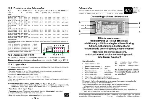
Connecting scheme future-value<br />
All future-value own:<br />
fullautomatic Li-Po cut-off circuit,<br />
additionally a Lithium single-cell monitoring,<br />
fullautomatic timing adjustment and<br />
fullautomatic switching frequency selection!<br />
Integrated blocking capacitors,<br />
anti-spark circuit avoids connecting spark,<br />
data logger function!<br />
schulze<br />
elektronik<br />
gmbh<br />
Key to illustration:<br />
1.1 - = negative brown or black<br />
1 Receiver cable, 3-lead<br />
1.2 + = positive red<br />
2 Battery connection neg. (-) . . schwarz<br />
1.3 p = pulse orange or white<br />
3 Battery connectin pos. (+) . . red<br />
4 Motor connection a . . . . . red/yellow<br />
5 Motor connection b . . . . . yellow/yellow<br />
6 Motor connection c . . . . . blue/yellow<br />
7 10-pin single cell voltage monitoring input<br />
8 5 V-SIO to communicate with a PC / Laptop computer<br />
Please note the following guidelines, which apply when you are connecting the<br />
motor and reversing its direction of rotation:<br />
1) The controller can be used with sensorless and sensor-controlled motors.<br />
(If your motor is sensor-controlled, the 5-pin connector is not used.)<br />
2) The three motor cables can be connected in any order<br />
3) To reverse the direction of rotation you have to swap over two of the three motor cables;<br />
we recommend that you swap the two outer wires.<br />
To avoid reception errors:<br />
Keep motor leads as short<br />
as possible!<br />
<strong>Schulze</strong> <strong>Elektronik</strong> <strong>GmbH</strong> • Prenzlauer Weg 6 • 64331 Weiterstadt • Fon: 06150/1306-5, Fax: 1306-99<br />
www.schulze-elektronik-gmbh.com • Germany • hotline@schulze-elektronik-gmbh.com<br />
4<br />
5<br />
6
Dear customer,<br />
Congratulations on your choice of a future speed controller, which is a micro-computer controlled<br />
unit developed and manufactured entirely in Germany, designed for brushless and sensorless<br />
3-phase rotary current motors.<br />
future controllers have the most intelligent, comprehensive software, which means that this<br />
speed controller is capable of operating virtually any brushless motor currently on the market<br />
with optimum efficiency.<br />
The ips (intelligent programming system)makes it as simple as possible to configure the controller<br />
to match any radio control system and operating mode: The transmitter stick travel settings of<br />
the wing programs is fully automatical, the operating modes for extended soft start or reverse gear<br />
are managed by simple position settings of the transmitter stick. Moreover the future-value can<br />
be configured by the future-soft.<br />
Contents<br />
Chapter Subject Page<br />
1 Warning notes, cautions . . . . . . . . . . . . . . . . . . . . . 3<br />
2 Ensuring safe, trouble free operation . . . . . . . . . . . . . . 4<br />
3 Intended applications and common highlights . . . . . . . . . 5<br />
4 Protective circuits . . . . . . . . . . . . . . . . . . . . . . . . . 6<br />
5 Monitor displays . . . . . . . . . . . . . . . . . . . . . . . . . . 7<br />
6 Installing and connecting the unit . . . . . . . . . . . . . . . . 7<br />
7 Connector systems and mounting instructions, Servos . . . . 8<br />
8 Using the controller for the first time . . . . . . . . . . . . . . 10-17<br />
8.1 ips - the intelligent programming system . . . . . . . . . . . . . . 10<br />
8.2 Symbols and terminology . . . . . . . . . . . . . . . . . . . . . . 11<br />
8.3.1 Mode setting for Wing aircraft models; brake on . . . . . . . . . . 12<br />
8.3.2 Mode setting for Wing aircraft models; geared motor, brake on . . 13<br />
8.3.3 Mode setting for Wing aircraft models; brake off . . . . . . . . . . 14<br />
8.3.4 Mode setting for Wing aircraft models; geared motor, brake off . . 15<br />
8.3.5 Mode setting for Boat models; reverse off . . . . . . . . . . . . . 16<br />
8.3.6 Mode setting for Boat models; reverse on . . . . . . . . . . . . . 17<br />
8.4 Changing the part-load switching frequency. . . . . . . . . . . . 18<br />
8.5 Changing the motor timing . . . . . . . . . . . . . . . . . . . . . 18<br />
8.6 Common about the cut off voltage . . . . . . . . . . . . . . . . . 18<br />
9 Tips . . . . . . . . . . . . . . . . . . . . . . . . . . . . . . . . . 20<br />
10 Accessories . . . . . . . . . . . . . . . . . . . . . . . . . . . . 21<br />
11 Legal matters . . . . . . . . . . . . . . . . . . . . . . . . . . . 22<br />
12 Specifications / Product overview / interfaces . . . . . . . . . 23<br />
12 Specifications<br />
12.1 Key to product summary future-value on the next page<br />
Weight: Excluding - including cables<br />
Current rating: Nominal current / maximum current: The excess current level lies above<br />
the maximum current value for each unit.<br />
The nominal current value is the continuous current at full throttle at which the future can<br />
be operated when connected to a 2 Ah battery without forced cooling. The nominal current<br />
value actually achieved may vary in either direction with different types of motor, rotational<br />
speeds and cell counts.<br />
Throttle, brake: Internal resistance of the MOSFETs, based on data sheet values (25°C).<br />
At 125°C the resistance is about 40% higher. For this reason you should always provide<br />
an effective flow of cooling air over the future to prevent it getting too hot.<br />
Pulse times: Allowed range: 0.8 ms ... 2.5 ms, cycle time: 10 ... 30 ms.<br />
Rotational speed: The rotational speed stated above is the limit value for a 2-pole motor<br />
(...P2). The following division factors apply: P4= /2; P6= /3; P8= /4; P10= /5.<br />
BEC: The stated peak current is dictated by the maximum current value of the 5V<br />
voltage regulator; it can only flow for less than 0.5 seconds, followed by a cooling-off period.<br />
The stated continous current is much lower and is determined by the maximum power<br />
dissipation of the voltage regulator and the heat dissipation of the future-PCB (4.5 W)<br />
(U = U - 5 V BEC voltage).<br />
loss battery<br />
Pay attention when connecting micro-servos: the current consumption is mostly 2...3<br />
times higher than the current of the Graupner C341 servo! The BEC System can be overload<br />
by temperature when using more than 8 Ni-cells (3 Lithium cells) and more than 3<br />
servos!<br />
Part-load-switching frequencies: 7 up to 35,2 kHz - automatically selected/adjusted.<br />
Soft-start: The soft-start feature on throttle and brake is optimized for the requirements<br />
in aircraft or boats. Beyond that the soft start can be adapted (slow down) to leightweight<br />
and fragile gears.<br />
Temperature: Overtemperature threshold is approximately 110°C.<br />
Note: If you have been using a sensor-controlled speed controller, you may find<br />
that now your motor’s maximum speed is different when you use the future. The timing of<br />
sensor-equipped motors is set for a particular rotational speed and a particular load (similar<br />
to the advance setting of an internal combustion engine’s timing), but the future automatically<br />
optimises the timing (within the pre-setted timing) for maximum efficiency under<br />
all load conditions. This means that the timing does not depend on the position of the<br />
speed sensors as dictated by the mechanical design, nor on the accuracy with which they<br />
are installed. The net result is that you may find that the maximum rotational speed of your<br />
motor is higher - combined with higher current; or lower - combined with lower current.<br />
For this reason it may prove necessary to experiment with new propeller sizes when you<br />
make the switch to a sensorless controller or you simply use the timing adjustment features<br />
of this type of future.<br />
- 2 e - - 23 e -
11 Legal matters<br />
11.1 Warranty<br />
All <strong>Schulze</strong> devices are carefully checked and tested before dispatch.<br />
If you have a complaint, send the unit back to us with a clear description of the fault.<br />
A message such as "doesn't work properly" or "software error" doesn't help us much!<br />
For all supply of warranty services our Terms of Sale and Supply are applicable (see<br />
<strong>Schulze</strong> Homepage).<br />
One further note:<br />
If a problem arises with any schulze product, send it directly to us without interfering with<br />
it in any way.<br />
Changes or extensions of the device can lead to additional costs if these impede or<br />
prevent services.<br />
Non-suitable components will be replaced or build back to the delivered condition at the<br />
owners expense without any consultation.<br />
This ensures that we can repair the unit quickly, pick up warranty faults without any<br />
dispute, and keep costs to a minimum.<br />
You can also be sure that we will fit genuine replacement parts which will work properly in<br />
your unit. Unfortunately we have had bad experience with third-party Service Centres<br />
which claim technical competence. Note also that any out-side interference with our<br />
products invalidates the warranty. Incompetent attempts at repair can cause further<br />
damage. We often find it impossible to estimate the repair cost of devices in such<br />
condition, and in certain circumstances we are then obliged to decline to repair it<br />
altogether.<br />
11.2 CE approval<br />
All <strong>Schulze</strong> devices satisfy all relevant and mandatory EC directives:<br />
These are the<br />
EMF directive 89/336/EWG: 3.May 1989 plus<br />
additional changes up to 3. January 1994<br />
The product has been tested to meet the following basic technical standards:<br />
Interference radiation: DIN EN 55014-1: 2003-09<br />
Interference susceptibility: DIN EN 55014-2: 2002-08<br />
You are the owner of a product whose design and construction fulfil the safety aims of the<br />
EC for the safe operation of devices.<br />
The approval procedure includes a test of interference radiation, i.e. of interference<br />
generated by the speed controller. This speed controller has been tested under practical<br />
conditions at maximum load current and with a large number of cells, and remains within<br />
the interference limits.<br />
A less stringent test would be, for example, to measure interference levels at a low<br />
current. In such cases the speed controller would not produce its maximum interference<br />
level.<br />
The procedure also includes also a test of interference susceptibility, i.e. the extent to<br />
which the device is vulnerable to interference from other devices. The test involves<br />
subjecting the speed controller to RF signals similar to those produced by an RC transmitter<br />
or a radio telephone.<br />
- 22 e -<br />
1 Warning notes, cautions<br />
Electric motors fitted with propellers are dangerous<br />
and require proper care for safe operation.<br />
Keep well clear of the propeller at all<br />
times when the battery pack is connected.<br />
Technical defects of an electrical or mechanical<br />
nature may result in unintended motor<br />
runs; loose parts may cause serious personal<br />
injuriy and/or property damage.<br />
The CE-certificate on the speed controller<br />
does not absolve you from taking proper care<br />
when handling the system!<br />
Speed controllers are exclusively for use in<br />
RC models. Their use in man-carrying models<br />
is prohibited.<br />
Speed controllers are not protected against<br />
reverse polarity (+ terminal and - terminal reversed).<br />
Connecting the battery pack to the<br />
motor leads of the controller will almost certainly<br />
cause irreparable damage.<br />
Electronic equipment is sensitive to humidity.<br />
Speed controllers which have got wet may<br />
not function properly even after thorough drying.<br />
You should send them back to us for<br />
cleaning and testing.<br />
Do not use speed controllers in conjunction<br />
with a power supply connected to the mains.<br />
Energy reversal can occur when the motor<br />
slows down and stops, and this may damage<br />
the power supply or cause an over-voltage<br />
condition which could damage the controller.<br />
Never disconnect the flight pack while the<br />
motor is running, as this could cause damage<br />
on a speed controller.<br />
Please take care when switching off the receiver<br />
battery: depending on the receiver you<br />
are using, it may send an incorrect throttle<br />
signal to the future at this moment, which<br />
could then cause the motor to burst into life<br />
unexpectedly.<br />
If you are using a future with BEC system:<br />
a) On no account connect a separate receiver<br />
battery or an electronic battery switch (two<br />
receiver batteries), as this may cause damage<br />
to the speed controller and could cause<br />
current to flow from the receiver battery to<br />
the motor.<br />
- 3 e -<br />
b) If you want to use a separate receiver battery<br />
cut through the + wire in the receiver cable,<br />
or pull it out of the connector if possible.<br />
However, for greater protection against motor-inducted<br />
interference it is always better to<br />
use a speed controller with an opto-coupler.<br />
Protect the speed controller from mechanical<br />
loads, vibration, dirt and contamination.<br />
Keep the cables to the motor as short as<br />
possible (max. length = 10 cm / 4”).<br />
Do not exceed the maximum stated length of<br />
cable between battery and future (max.<br />
length: 20 cm / 7...8"). The wiring inside the<br />
battery pack must also be as short as possible.<br />
Use in-line soldered “stick” packs.<br />
For the same reason, use a clamp-type amperemeter,<br />
not a series meter with shunt resistor.<br />
Never leave the flight battery connected<br />
when ...<br />
... the model is not in use and/or<br />
... the battery pack is being charged.<br />
Although some speed controllers feature a<br />
separate On/Off switch, this does not isolate<br />
it completely from the battery.<br />
Speed controllers can only function properly<br />
if they are in full working condition. The protective<br />
and monitoring circuits can also only<br />
work if the speed controller is in good operating<br />
condition.<br />
In the case of motor failure (e.g.short circuits<br />
in the windings) the over-temperature sensor<br />
in the controllers may react too slowly to prevent<br />
damage. switch the motor off immediately<br />
to prevent permanent damage to the speed<br />
controller.<br />
Note: Please remember that the monitoring<br />
circuits are unable to detect every abnormal<br />
operating condition, such as a short between<br />
the motor cables. Note also that a stalled motor<br />
will only trip the current limiter if the motor's<br />
stall current is well above the controller's<br />
peak current. For example, if you are using<br />
an 80 A controller in conjunction with a 20<br />
A motor, the current monitor will not detect an<br />
excessive current even when the motor is<br />
stalled.
2 Ensuring safe, trouble-free operation<br />
Use only compatible connectors. A 2 mm<br />
pin cannot provide reliable contact in a 2.5<br />
mm socket. The same applies with 2mm<br />
gold-contact pins and 2 mm tin-plated<br />
sockets.<br />
Please also remember that ...<br />
... the wiring of your RC-components must<br />
be checked regularly for loose wires, oxidation,<br />
or damaged insulation, especially<br />
when using a BEC system.<br />
... your receiver and the aerial must be at<br />
least 3 cm (>1") away from motor, speed<br />
controller and high-current cables. For example,<br />
the magnetic fields around the<br />
high-current cables can cause interference<br />
to the receiver.<br />
... all high-current cables must be as short<br />
as possible. Maximum length between<br />
flight pack and speed controller should<br />
never exceed 20 cm (7"), between speed<br />
controller and motor: 10 cm (4").<br />
... all high-current cables longer than 5 cm<br />
(2") must be twisted together. This applies<br />
in particular to the motor power cables,<br />
which are very powerful sources of radiated<br />
interference.<br />
... in model aircraft: half of the receiver<br />
aerial's length should be routed along the<br />
fuselage, the other half should be allowed<br />
to trail freely (take care not to tread on it).<br />
Do not attach the end of the aerial to the<br />
fin!<br />
... in model boats: half of the receiver aerial's<br />
length should be deployed inside the<br />
hull above the waterline, the other half<br />
should be threaded into a small tube<br />
mounted upright.<br />
Every time you intend to use the power<br />
system - before you turn on the receiver<br />
- make sure that ...<br />
... no one else is using the same frequency<br />
(identical channel number).<br />
... your transmitter is switched on and the<br />
throttle stick is (as a rule) in the STOP position<br />
(exceptions see Section 8).<br />
- 4 e -<br />
Carry out a range check before each flight.<br />
Ask an assistand to hold the model aircraft<br />
and set the throttle stick to the half throttle<br />
position. Collapse the transmitter aerial.<br />
Walk away from the model to the distance<br />
stated by the RC system manufacturer<br />
(this might be a distance of about 50-60 m<br />
= 200'). Make sure that you still have full<br />
control of the system at this range.<br />
As a general rule: receiver interference is<br />
more likely to occur when using a controller<br />
with BEC system, as these units do not<br />
feature an opto-coupler with its optical link.<br />
When Ni-Cd batteries approach the end of<br />
their charge, voltage falls drastically and<br />
quickly. The future detects this and reduces<br />
power to the motor automatically. This<br />
should leave sufficient energy to bring your<br />
model safely back home. However, if you<br />
use a small number of cells of high internal<br />
resistance and operate at high motor currents,<br />
the controller may reduce power before<br />
the pack is discharged. You can eliminate<br />
this problem by using low resistance<br />
straps to connect the cells, or use the direct<br />
cell-to-cell soldering technique<br />
(“sticks”) and short, heavy-gauge wire if<br />
you assemble your own batteries.<br />
Your receiver also benefits from the stability<br />
of the voltage supplied from the battery<br />
by a BEC system. If the BEC voltage is<br />
stable, the receiver is less liable to suffer<br />
interference.<br />
The CE symbol is your guarantee that the<br />
unit meets all the relevant interference<br />
emission and rejection regulations when it<br />
is in use.<br />
If you encounter problems operating the<br />
future controller, please note that many<br />
problems are due to an unsuitable combination<br />
of receiving system components, or<br />
an inadequate installation in the model.<br />
10 Accessories<br />
10.1 <strong>Schulze</strong> BalCab10-Verl<br />
Ready-made balancer cable for connecting<br />
<strong>Schulze</strong> LiPoPerfekt battery packs to<br />
the measuring inputs. 10-leads for 2 ... 4<br />
cells in series.<br />
10.2 BalCab20-Verl (without illustration).<br />
As above, but 20-leads (2...8 cells).<br />
10.3 future-soft<br />
Software similar to the „u-soft“ to configure<br />
the future-value via PC/Laptop<br />
(e.g. softstart, under voltage limits, e.t.c).<br />
In preparation.<br />
10.4 USB-adapt-uni<br />
Active adapter to connect the 5 V-SIO of<br />
the future-value with the USB interface<br />
of a PC or Laptop.<br />
10.5 USB-Kabel (without illustration)<br />
Cable to connect the USB-adapt-uni with<br />
the PC or Laptop.<br />
10.6 prog-adapt-uni<br />
Active adapter to connect the 5 V-SIO of<br />
the future-value with the RS232 interface<br />
(COMx) of a PC or Laptop.<br />
Adapter cable for Thunder-/Flight-Power<br />
batteries (pin spacing 2.0 mm)<br />
10.81 FutValAdapt-TP8 2s - 8s<br />
Adapter cable for Kokam / Robbe /<br />
Graupner batt. (pin spacing 2.54 mm)<br />
10.82 FutValAdapt-Ko6 2s - 6s<br />
10.83 FutValAdapt-Ko8 2s - 8s<br />
10.84 FutValAdapt-Ko2x4 2*2s-4s<br />
- 21 e -<br />
10.8x<br />
10.82<br />
Free<br />
download<br />
from the<br />
<strong>Schulze</strong> Homepage<br />
(10.83 similar)<br />
10.81<br />
10.84
9 Tips<br />
9.1 Rotational speeds<br />
future-value speed controllers can drive the motor - in comparison to speed controllers of other<br />
manufacturers - with slightly different rotational speed at the same supply voltage.This effect is<br />
caused by the automatically setted (and varied) timing. The resultant difference of the rotational<br />
speed can be higher or lower.<br />
9.2 Start-up problems, controller faults<br />
We have now established that the usual cause of unreliable motor start-up problems is poor<br />
contact in the connectors.<br />
Inadequate contact can result in faults due to excessive voltage, especially when the highvoltage<br />
versions of the future are used, because the high resistance of the connectors prevents<br />
the voltage being passed back into the battery at mid-range settings, and especially during<br />
braking.<br />
Examples of poor practice<br />
• Solder between the contact segments of the plug<br />
-> Remedy: solder on a brand-new plug.<br />
• Resin (electronic solder flux) under the contact segments of the plug<br />
-> Remedy: remove flux residues with meths or contact cleaner.<br />
• Over-long leads between battery and future<br />
-> Remedy: shorten to permissible length (chapter 6).<br />
• Lack of spring pressure in the contact segments<br />
-> Remedy: solder on brand-new plugs, and be sure to cool the segments when soldering!<br />
• Poor-quality connectors. Oxidised sockets (black inside), discoloured gold plating (greenish or<br />
grey).<br />
-> Remedy: use high-quality plugs and sockets from a brand-name manufacturer<br />
-> Remedy: don’t use cheap goods from the Far East<br />
-> Remedy: contact segments should be made of copper-beryllium - no mild steel contacts!<br />
9.3 Overheating motors<br />
If you are using a Graupner Carbon 70, Hacker, Kontronik BL or Simprop motor, never shorten<br />
the winding wires which project from the motor. The strands are coated with high-temperature<br />
lacquer, and it is impossible to solder through this material. To obtain a sound soldered joint you<br />
must mechanically remove the lacquer coating all round each individual strand. Any strands<br />
which are not soldered or fractured cause an increase in current flow through each remaining<br />
wire, and this in turn causes a lower efficiency and increase in motor temperature.<br />
9.4 Interferences<br />
We regognized some interference in combination with certain types of motors. These interferences<br />
occurs in combinations with different manufacturers of controllers.<br />
9.5 Multi motor operation<br />
In general terms we do not recommend operating multiple motors with a future. From some of<br />
our customers we have heard that this certainly works with some (but not all) Aveox, Hacker,<br />
Kontronik or Lehner motors, provided that the currents do not exceed the permissible maximum<br />
values for the speed controller concerned. However, we cannot guarantee that both motors will<br />
rotate over the full load range.<br />
It is never permissible to run more than one Plettenberg or Köhler motor connected to a single<br />
future: you must use a separate future for each motor. However, you can certainly power both<br />
controllers from a single drive battery.<br />
- 20 e -<br />
3 Intended applications and common highlights<br />
Common highlights<br />
All future of this series can be used for Wing-<br />
Aircraft-Models or Boat-Models. Some types<br />
include an opto-coupler which ensures minimum<br />
possible transfer of interference to your receiver.<br />
All future which includes a „W“ in the Type<br />
declaration are equipped with a boat program<br />
and own a small tube to connect the cooling<br />
water. They are splash water protected (but ist is<br />
not allowed to use them wet). The boat program<br />
includes a reverse gear.<br />
Better than 500-step resolution over the whole<br />
control range for extremely fine speed control.<br />
„Auto-arm“ function and „power on reset“.<br />
„ips“ (intelligent programming system) with no<br />
pots! The future automatically configures itself<br />
every time to the stick travel when you go airborn.<br />
During the “Power-On” process the motor acts as<br />
a loudspeaker to give you audible confirmation of<br />
the procedure.<br />
All future-value own a fully automatic timing and<br />
part load switching frequency adjustment. The<br />
motor characteristics are measured when the<br />
power battery is connected to the future-value.<br />
This helps to run the different motor types near<br />
their optimum.<br />
All future-value are equipped with connectors for<br />
the Lithium single cell voltage monitoring.<br />
The <strong>Schulze</strong> BalCab10 and <strong>Schulze</strong>-BalCab20<br />
connectors and some connectors with a pin<br />
spacing of 2.54 mm (Kokam, Robbe, Graupner)<br />
can be connected without any adapter (See<br />
connecting example in chapter 8.4).<br />
Safety hints:<br />
The future-value with BEC system are „linear“<br />
BEC systems. In comparison to the „switched“<br />
BEC systems - the linear systems have the<br />
advantage, that the receiver in the model can not<br />
be interfered by the switching frequency (because<br />
there is none) of the BEC. The use is more<br />
safe.<br />
The future-value with BEC system are galvanically<br />
coupled by the „-Akku“ (neg. battery) cable<br />
with the receivers GND. The additionally interference<br />
suppressing effect of a transmission by<br />
light (opto coupler) is not existant. Even when<br />
you use a future-value with opto coupler and an<br />
external BEC system is used then the opto coupler<br />
is bridged by the external BEC and for this<br />
reason there is no longer a positive effect.<br />
Umrechnungsfaktor: Eine Lithiumzelle entspricht etwa 3 ... 3,3 Ni-Cd oder Ni-MH Zellen<br />
- 5 e -<br />
Low voltage types with BEC<br />
fut-val-12.40e(W)<br />
For 6-12 Ni-Cd or Ni-MH cells<br />
or 2-4 Lithium cells.<br />
For motors up to 40A*; peak 55 A.<br />
5 V / 3 A BEC System; peak 4.5 A.<br />
fut-val-12.60e(W)<br />
For 6-12 Ni-Cd or Ni-MH cells<br />
or 2-4 Lithium cells.<br />
For motors up to 60A*; peak 80 A.<br />
5 V / 3 A BEC system; peak 4.5 A.<br />
Low voltage types with opto<br />
coupler<br />
fut-val-18.40o(W)<br />
For 6-18 Ni-Cd or Ni-MH cells<br />
or 2-6 Lithium cells.<br />
For motors up to 40A*; peak 55 A.<br />
The receiver pulses are coupled via an opto<br />
coupler to the controller. This means that the<br />
receiver is galvanically separated from the<br />
motor battery. For this reason you are in<br />
need of a receiver battery**.<br />
24 cells high voltage type<br />
with opto coupler<br />
fut-val-24.60o(W)<br />
For 6-24 Ni-Cd or Ni-MH cells<br />
or 2-8 Lithium cells.<br />
For motors up to 60A*; peak 80 A.<br />
The receiver pulses are coupled via an opto<br />
coupler to the controller. This means that the<br />
receiver is galvanically separated from the<br />
motor battery. For this reason you are in<br />
need of a receiver battery**.<br />
(*) The nominal current value is the continuous<br />
current at full throttle at which the<br />
future can be operated when connected to a<br />
2 Ah battery without forced cooling.<br />
(**) We recommend <strong>Schulze</strong> LiPoRxII<br />
receiver current/voltage supplies.<br />
On no account use Ni-MH batteries in the<br />
size AA or AAA. As a rule these batteries<br />
have a higher internal resistance than other<br />
sizes and Ni-MH batteries are not able to<br />
supply high currents at low temperatures.
4 Protective circuits<br />
Note: the monitor circuits are effective, but they<br />
cannot detect every possible operating condition.<br />
Temperature monitor<br />
The temperature monitor throttles down the motor<br />
and later switches off the motor. You can reset<br />
the unit using the "auto-arm" function (throttle<br />
stick to stop for about 2 sec.)<br />
If the motor windings are short-circuited the temperature<br />
monitor reacts too slowly to prevent<br />
damage. switch the motor off immediately to<br />
avoid permanent damage to the speed controller.<br />
Voltage monitor<br />
As soon as the voltage of the drive battery falls<br />
back to the under voltage threshold the motor is<br />
throttled back (more information about the threshold<br />
value see chapter 8.6).<br />
If the situation which caused the controller to<br />
throttle back continues for more than a short<br />
time, the unit switches the motor off.<br />
Of course, you can re-start the motor again<br />
briefly by moving the throttle stick back to "stop"<br />
for about 2 seconds to re-arm the system.<br />
If you use a future without BEC system you retain full<br />
control of the model until the receiver battery is flat;<br />
if you use a future with BEC system the power<br />
system and the model remain fully controllable<br />
until the last usable energy in the flight pack is<br />
exhausted. We can not predict how long you can<br />
still control your model with the residual battery<br />
charge as this depends on many parameters<br />
such as the number of cells in the pack, the cell<br />
type, actual motor current and the way you control<br />
your model. The only solution is for you to<br />
time the period yourself with the model on the<br />
ground. If the voltage monitor trips, i.e. the motor<br />
starts to throttle back without your intervention,<br />
you should stop the motor at once with the throttle<br />
stick in any case so that you have the maximum<br />
possible reserve of power.<br />
Maximum speed monitor<br />
If maximum rotational speed of the motor will<br />
exceed, future throttles down. In this state do not<br />
use longer then 1 second because some motors<br />
could over heat.<br />
Because of this: Do not run motor without airscrew,<br />
possibly the motor switches off after 2<br />
seconds.<br />
Minimum speed monitor<br />
To ensure that the controller detects the rotor<br />
position reliably, this series of future types sets a<br />
defined minimum rotational speed.<br />
This protective function can cause the motor to<br />
be reluctant to start up if its torque limit is exceeded.<br />
If this should happen, check (measure!)<br />
that the maximum permissible motor current is<br />
not exceeded. In this case a propeller one step<br />
smaller in diameter must be used.<br />
Current monitor<br />
The future controllers feature a current monitor<br />
circuit which trips when the current rises above<br />
the specified maximum value. If the motor is<br />
stalled, the motor is throttled back. This means,<br />
that a motor which draws an excessive current<br />
will never reach full-throttle, and the current may<br />
stay below the specified maximum value. If<br />
future is some seconds in current limiting mode,<br />
it will disarm itself (switching off the motor). rearming<br />
= 2 seconds “stopp”.<br />
Receiver signal monitor<br />
If the receiver signal fails, or the signal is longer<br />
or shorter than the usual range of values, the future<br />
controller reverts to hold mode for about 300<br />
milliseconds (helicopter = 1.5 s) before switching<br />
to disarmed mode.<br />
This protection function enables you to eliminate<br />
receiver interference before you actually<br />
lose your model, perhaps by modifying the installation<br />
or changing the radio control components.<br />
Reverse polarity protection<br />
The future is not protected against reverse polarity!<br />
Anti-Spark<br />
The future have feature an additional circuit<br />
which avoids the connecting spark (and for this<br />
reason the damage on the connectors) when the<br />
future is connected to the power battery.<br />
Watchdog<br />
If this circuit is tripped the speed controller stops<br />
working briefly and then reverts to normal operation.<br />
Error codes<br />
Under certain circumstances future controllers<br />
refuses to work after connection to the power<br />
battery and beeps - if possible - an error code:<br />
4 beeps:<br />
battery weak (empty or high impedance) or<br />
battery cables too long. (Remedy e.g. by adding<br />
a low ESR electrolytic capacitor near the future -<br />
see picture in chapter 6).<br />
5 beeps:<br />
motor too strong or short circuit in the windings.<br />
6 beeps:<br />
double tone beep, normal beep, double tone ...<br />
(motor defective, battery weak, future defective)<br />
- 6 e -<br />
Especially we do not measure the „+“ and „-“ battery voltage which<br />
are supplied in any case via the power cables of the future-value.<br />
The assignment of the measuring inputs is as shown below. It is not<br />
necessary that the individual cell voltages must be ascendant to<br />
the numbers in the figure below and it is also not necessary that<br />
they must be completely connected because an additional protection<br />
is existing through the total battery voltage.<br />
The single cell voltages are mesured<br />
97531 according to the assignment of a<br />
5 V-SIO<br />
....<br />
<strong>Schulze</strong> BalCab20 socket on the<br />
1 2 3 4<br />
pins 2...8. The „+“ (positive) terminal<br />
of the cells can be connected in any<br />
108642 order to the pins 2-8.<br />
- Akku<br />
BalCab 20<br />
pin 1 mark<br />
+ Akku<br />
BalCab 10<br />
Kokam<br />
5s<br />
GND - do not connect<br />
Kokam<br />
2s<br />
8.6.3 When the Lithium single voltage monitoring detects an undervoltage<br />
then the trottle reduction works as follows:<br />
If one (or more) cells reach the under voltage limit then the motor<br />
is trottled down to about 80 %. This is „the hint“ to the pilot to prepaire<br />
the landing immediately. Later the motor will be throttled<br />
down analogous to the battery voltage until it shuts off completely.<br />
8.6.4 The configuration program „future-soft“ (for PCs; in preparation)<br />
can be used to configure special cut-off characteristics in the future-value<br />
(Similary to the characteristics of the <strong>Schulze</strong> LiPoDi-<br />
MATIC). The 5 V-SIO has to be connected via an adapter (chapter<br />
10.4 - 10.6) to the PC or Laptop.<br />
- 19 e -
8.4 Selection of the part load switching frequency<br />
The optimum of the part load switching frequency is selected fully<br />
automatically from the future-value on the basis of the connected<br />
motor. These data are measured during the initialization of the future-value<br />
e.g. during the „Power-On“ melody. If the motor should<br />
be not connected at this moment then the measuements will be<br />
done later when the motor is connected.<br />
8.5 Selection of the motor timing<br />
The optimum of the motor timing is selected fully automatically<br />
from the future-value on the basis of the connected motor, the<br />
supply voltage, and the differnt loads in the momentary operating<br />
point.<br />
8.6 Selection of the under voltage cut off<br />
The normal undervoltage cutoff of the motor is fully automatically of<br />
the future-value on the basis of the measured voltage at the moment<br />
when the controller is connected to the battery<br />
8.6.1 is the power supply fallen down to 58,6 % of the connected voltage<br />
then the power of the motor will be reduced in a first step and<br />
later the motor will be completely shut off to avoid a deep discharge<br />
of of the battery.<br />
This type of undervoltage protection is proved since several years<br />
and works in like manner reliable with all Nickel-Cadmium, Nickel-<br />
Metallhydrid, Lithium-Ionen, Lithium-Polymer und Lithium-Eisenoxid<br />
batteries (so far as the batteries are fairly full).<br />
8.6.2 The future-value offers additionally the possibility to measure the<br />
single cell voltages of Lithium batteries and recognizing the<br />
„weakest“ cell, (i.e. the cell with tle lowest voltage) and react on this<br />
adequately. The standard pre-selection for Li-Po is 3.0 V per cell<br />
and for Li-FePO4 it is 2.2 V per cell.<br />
The measuring inputs are located on the front side of the futurevalue.<br />
They are wired in such a way that you can connect and utilize<br />
<strong>Schulze</strong> BalCab10 and <strong>Schulze</strong> BalCab20 sockets directly<br />
under consideration of the plug direction (pin 1). Moreover all sokkets<br />
with a pin spacing of 2,54 mm and lower cell counts fits without<br />
any adapter. (See also Chapter Accessories 10.8+).<br />
Note: The 10-pin connector is not completely wired.<br />
- 18 e -<br />
5 Monitor displays<br />
The future is not fitted with LED to indicate<br />
its operating state.<br />
However, when the unit is being configured<br />
6 Installations, connections<br />
6.1 Installing in the fuselage<br />
Velcro (hoop and loop) tape is the ideal method<br />
of mounting the controller in the fuselage. Do not<br />
pack the future in foam as this may lead to a<br />
heat build-up in the controller.<br />
6.2 Receiver connection<br />
Connect the (3-wire) receiver cable attached<br />
to the future to the receiver servo output corresponding<br />
to the throttle stick on the transmitter<br />
(or a switch if that is your preference).<br />
The future receives its control signal via this<br />
receiver socket.<br />
Check regularly especially in this case that<br />
the receiver cable is undamaged and firmly<br />
seated at the future.<br />
On no account connect a separate receiver battery<br />
or an electronic battery switch (two receiver<br />
batteries) to BEC equipped controllers, as this<br />
may cause damage to the speed controller and<br />
could cause current to flow from the receiver<br />
battery to the motor.<br />
6.3 Length of connecting cables<br />
6.3.1 Power-connection battery future<br />
Do not exceed the maximum stated length of<br />
cable between battery and future (max.<br />
length: 20 cm / 7...8”), otherwise the speed<br />
controller may be damaged. This rule still applies<br />
even if your power system features a<br />
retractable (folding) motor, or your model<br />
necessarily includes a long battery cable!!!<br />
- 7 e -<br />
different beeps are generated from the motor<br />
dependent on the set stick points as a confirmation<br />
(See chapter 8).<br />
Battery packs which are assembled in a zigzag<br />
pattern also produce ”long cable” effects.<br />
Use in-line (end-to-end) soldered packs exclusively.<br />
Hint: If you use additional capacitors<br />
soldered to the battery cables then the<br />
“Anti Spark” circuit does not have an effect<br />
any longer.<br />
It is essential to use polarized gold-platedcontact<br />
connectors - fitting any other type of<br />
connector invalidates the warranty.<br />
Carry out regular maintenance! - Ensure<br />
that all connectors are absolutely clean at all<br />
times, and that the gold plating is not damaged.<br />
Connector contacts must be a bright<br />
gold colour, and must not exhibit any discoloration<br />
or deposit (flux, dirt, liquid, e.t.c.).<br />
Examine the inside of sockets carefully;<br />
bunched-contact plugs must also be cleaned<br />
between the core and the contact leaves!<br />
Ensure that the plug contacts still have a<br />
strong spring force.<br />
Connectors which do not have a polarised<br />
insulator can be made safe (i.e. polarised) by<br />
soldering the future’s positive battery wire to a<br />
socket, and the future’s negative wire to a plug.<br />
We recommend that you choose your connectors<br />
from our selection in Section 7 - fitting any<br />
other type of connector invalidates the warranty.<br />
6.3.2 Power-connection future motor<br />
The cables to the motor should be kept as<br />
short as possible to avoid interferences to<br />
your receiver. Long cables tend to act as<br />
aerials and radiate interference; they also<br />
add unnecessary weight. Twist long cables.<br />
Carry out a range check when you set the<br />
throttle stick to the half throttle position.<br />
Cut down the existing motor cables to a<br />
length of no more than 10 cm. Do not extend<br />
the motor cables except in exceptional cases;<br />
although this generally does not harm to the<br />
future itself.<br />
Under no account is it allowed to wind ferrite<br />
cores on the motor wires!
7 Connector systems and mounting instructions; servos<br />
7.1 3.5 mm gold-contact connector system (pp35); max. load > 80A<br />
+ red plug wide sleeve narrow socket + red ( akku)<br />
battery future<br />
- black socket narrow sleeve wide plug - black ( akku)<br />
Caution: remove locating lug from battery cable. Do not remove lug from any cables<br />
attached to controllers or charge leads!<br />
Manufacturer’s information: the pp35 plug is very short, and this presents the<br />
danger that the contact spring could lose its resilience (spring force) due to excessive<br />
heat build-up during the soldering process. You can side-step the problem<br />
by keeping the temperature below 200°C as follows: either remove the contact<br />
carefully before soldering, or simply push the plug into a piece of wet finegrain<br />
sponge for soldering, or plug it in a 3.5 mm hole of a copper-block.<br />
Fit the connectors in the order shown above; the contacts are pressed in as follows:<br />
a. Place plastic sleeve vertically on table, grip end up.<br />
b. Push contact down into sleeve.<br />
c. Place 2.5mm wide screwdriver blade on top of cable solder joint inside sleeve.<br />
d. Tap screwdriver to press contact into sleeve until latch engages.<br />
7.2 CT4-4mm, CT2-2mm gold-contact connector system (rating CT4 up to 80A; CT2 to 30A)<br />
+ red sleeve wide plug socket sleeve narrow red ( akku)<br />
battery future<br />
- black sleeve narrow socket plug sleeve wide black ( akku)<br />
Fit the connectors in the order shown above; the contacts are pressed in as follows:<br />
a. Rest plastic sleeve on vice jaws with cables hanging down.<br />
b. Close vice jaws until cables are just free to move.<br />
c. Fit plug into socket and tap into sleeve until latch engages.<br />
d. Fit socket onto plug and tap into sleeve until latch engages.<br />
- 8 e -<br />
8.3.6 Mode setting for boat models with reverse gear<br />
Using the half throttle stick travel at “stick“-transmitters or<br />
for transmitters with pistol grip.<br />
(for all future-value types with „W“ at the end of the type declaration)<br />
a Receiver off (drive battery disconnected)<br />
b Set throttle stick to middle position („neutral“)<br />
c Switch transmitter on<br />
d Switch receiver on (connect drive battery)<br />
e future confirms „Power-On“,<br />
f waits about 1 second and calculates the full throttle and<br />
reverse position (learned neutral position + - 0,3 ms),<br />
g confirms neutral position with a single tone beep � and is<br />
armed!<br />
h Moving the transmitter stick towards full throttle starts the<br />
motor running forward.<br />
i Moving the transmitter stick towards full brake slows the<br />
propeller and model proportionally<br />
j If you leave the stick for longer than 1.7 seconds in the reverse<br />
position (over 75% reverse travel, i.e. less than 0.225 ms below<br />
the learned neutral position), then the motor will accelerate<br />
slowly in reverse.<br />
<strong>TXon</strong><br />
<strong>RXon</strong><br />
�����<br />
Undervoltage cutoff: 58.6% of the plug-in voltage or after a special<br />
configuration (Chapter 8.6).<br />
The learned configuration is kept in the future-value until the power<br />
battery is disconnected. A non-volatile configuration can be made<br />
via the „future-soft“ (Chapter 10.3).<br />
- 17 e -<br />
�
8.3.5 Mode setting for boats without reverse gear<br />
Using the full throttle stick travel at conventional remote control<br />
„stick“-transmitters.<br />
(for all future-value types with „W“ at the end of the type declaration)<br />
a Receiver off (drive battery disconnected)<br />
b Set throttle stick to the mechanical stop position<br />
(= „neutral“ for double stick travel)<br />
c Switch transmitter on<br />
d Switch receiver on (connect drive battery)<br />
e future confirms „Power-On“,<br />
f waits about 1 second, calculates the full throttle position<br />
(learned neutral position + 0,6 ms),<br />
g confirms neutral position with a single tone beep � and is<br />
armed!<br />
h Moving the transmitter stick towards full throttle starts the<br />
motor running forward.<br />
<strong>TXon</strong><br />
<strong>RXon</strong><br />
�����<br />
Undervoltage cutoff: 58.6% of the plug-in voltage or after a special<br />
configuration (Chapter 8.6).<br />
The learned configuration is kept in the future-value until the power<br />
battery is disconnected. A non-volatile configuration can be made<br />
via the „future-soft“ (Chapter 10.3).<br />
- 16 e -<br />
�<br />
7.3 MPX gold-contact connector system (green or red); max. load ~30A<br />
+ red heat-shrink socket plug heat-shrink + red ( akku)<br />
battery future<br />
- black heat-shrink socket plug heat-shrink -black ( akku)<br />
Fit the connectors in the order shown above; the contacts are soldered as follows:<br />
a. To center the contacts fit plug and socket together before soldering.<br />
b. Tin all 6 exposed solder terminals of plug or socket.<br />
c. Fit cable end into triangle of contacts, solder to all three solder terminals.<br />
d. Position heat-shrink sleeve and shrink over joint.<br />
7.4 2,0 / 2,5 mm gold-contact connector system; max. load ~30A<br />
+ red socket sleeve narrow sleeve wide plug + red ( akku)<br />
+ Kodierung +<br />
battery future<br />
- black socket sleeve narrow sleeve wide plug -black ( akku)<br />
Fit the connectors in the order shown above; the contacts are pressed in as follows:<br />
a. Place plastic sleeve vertically on table, grip end up.<br />
b. Push contact down into sleeve.<br />
c. Place 2.5mm wide screwdriver blade on top of cable solder joint inside sleeve.<br />
d. Tap screwdriver to press contact into sleeve until latch engages.<br />
7.5 Deans connector system; max. load ~ 50A<br />
+ red socket plug + red ( akku)<br />
battery future<br />
- black socket plug -black ( akku)<br />
- 9 e -
7.6 Suitable servos for BEC operation (selection)<br />
DYMOND D 60, D54, D47<br />
FUTABA 5102<br />
GRAUPNER C261, C341, C351, C3041, C3321<br />
HITEC HS55<br />
MEGATECH MTC FX200<br />
ROBBE FS40 #8433<br />
VOLZ Microstar, Wingstar, Zip<br />
8 Initial use<br />
8.1 ips, the intelligent programming system<br />
for configuring the future-value to suit your application<br />
In general terms: in its standard form the future works with all motors known<br />
to us, i.e. without you having to make any adjustments to it!<br />
If you have a transmitter with adjustable servo travel we recommend that you set<br />
throttle-servo to normal full travel, i.e. +/- 100%. Adjust Multiplex servo center<br />
pulse width to 1.5 ms (= -22% center or use uni-mode).<br />
The ips makes the automatic transmitter stick travel setup.<br />
The stick travel setup process is based on the previous standard procedure when<br />
the unit is first switched on, and is fully automatic:<br />
8.1.1 Under normal circumstances you simply proceed as previously: 1. Transmitter<br />
to stop, 2. Switch on receiver, 3. Connect flight pack / drive battery (future confirms<br />
this with ”Power-On” tones = flight pack / drive battery connected), then<br />
learns the Stop position and confirms this with a beep; it is then armed, 4. Hold<br />
model in launch / start position, 5. Apply full-throttle (future learns full-throttle<br />
point, confirms with brief drop in rotational speed), 6. Launch / Start model. The<br />
process configures both the brake point and the full-throttle point, so full stick<br />
travel is always available when you operate the motor, giving ultra-fine control.<br />
8.1.2 If you find the brief motor speed drop at the full-throttle setting disturbing or<br />
you don’t wish to apply full throttle at launch / start, there are alternative methods:<br />
8.1.2.1 Hold the model on the ground until the speed drop occurs and<br />
then start with half throttle or 8.1.2.2 configure the future-value to fixed stick<br />
travel points by means of the PC program future-soft.<br />
8.1.3 Hints:<br />
8.1.3.1 In the boat programs the controller only learns the neutral point; the fullthrottle<br />
position is a fixed margin from the learned neutral point.<br />
8.1.3.2 If your future beeps twice (double beep = full throttle position) when the<br />
transmitter stick is at the brake position, you must reverse the throttle channel<br />
using your transmitter’s servo reverse function. If you neglect to do this, the future<br />
will be armed (single beep) at the transmitter’s full-throttle setting, and run<br />
at full-throttle at the stop setting, which is not recommended!<br />
- 10 e -<br />
8.3.4 Mode setting without brake e.g. for sports wing aircraft<br />
with lightweight, fragile gear (extended soft start)<br />
(for all future-value types without „W“ at the end)<br />
a Receiver off (flight battery disconnected)<br />
b Set throttle stick to middle position<br />
c Switch transmitter on<br />
d Switch receiver on (connect flight battery)<br />
e future confirms „Power-On“,<br />
f waits about 1 second, confirms gear mode with<br />
three beeps ��� and remains disarmed<br />
g Move throttle stick quickly to full-throttle position and ...<br />
h waits about 1 second, confirms full throttle position with a<br />
double beep �� and remains disarmed<br />
i Move throttle stick quickly to stop position and ...<br />
... leave it there for about 1 second.<br />
j future confirms brake position with a single tone beep �<br />
and is armed!<br />
k The future is completely configured and the model can<br />
be flown.<br />
l Hold model in launch position, keep clear of danger area<br />
around propeller!<br />
m Model can be started with any trottle position you like.<br />
<strong>TXon</strong><br />
<strong>RXon</strong><br />
�����<br />
���<br />
Undervoltage cutoff: 58.6% of the plug-in voltage or after a<br />
special configuration (Chapter 8.6).<br />
The learned configuration is kept in the future-value until the power<br />
battery is disconnected. A non-volatile configuration can be made<br />
via the „future-soft“ (Chapter 10.3).<br />
- 15 e -<br />
��<br />
�
8.3.3 Mode setting without brake e.g. for<br />
sports wing aircraft models<br />
(for all future-value types without „W“ at the end of the type<br />
declaration)<br />
a Receiver off (flight battery disconnected)<br />
b Set throttle stick to full throttle position<br />
c Switch transmitter on<br />
d Switch receiver on (connect flight battery)<br />
e future confirms „Power-On“,<br />
f waits about 1 second, confirms full throttle position with a<br />
double beep �� and remains disarmed<br />
g Move throttle stick quickly to stop position and ...<br />
... leave it there for about 1 second.<br />
h future confirms brake position with a single tone beep �<br />
and is armed!<br />
i The future is completely configured and the model can be<br />
flown.<br />
j Hold model in launch position, keep clear of danger area<br />
around propeller!<br />
k Model can be started with any trottle position you like.<br />
<strong>TXon</strong><br />
<strong>RXon</strong><br />
�����<br />
Undervoltage cutoff: 58.6% of the plug-in voltage or after a<br />
special configuration (Chapter 8.6).<br />
The learned configuration is kept in the future-value until the power<br />
battery is disconnected. A non-volatile configuration can be made<br />
via the „future-soft“ (Chapter 10.3).<br />
- 14 e -<br />
��<br />
�<br />
8.1.3.3 The following pages explain exactly which type-specific setup facilities (operating<br />
modes) are available. They are sub-divided into the different applications<br />
of model aircraft and boats.<br />
8.2 Symbols and terminology<br />
Stick or throttle stick: The throttle stick on the transmitter or<br />
the trigger on a pistol type transmitter.<br />
Middle position or neutral position of a self neutralising stick<br />
(technically 1.36 ... 1.67 ms pulse width). This is the position<br />
where the motor just barely runs at a boat program.<br />
Brake position or idle position<br />
Position of the throttle stick where the motor stops or just barely<br />
runs.<br />
Full-throttle position<br />
100% voltage passed to the motor.<br />
Wait (e. g. 0.5 seconds)<br />
Audible indicators<br />
These indicators are only audible when a motor is attached, as<br />
the motor itself acts as the loudspeaker.<br />
Power-On melody (Flight-/drive battery connected)<br />
Single beep (Brake position detected/learned, future is armed)<br />
Double beep (Full throttle position detected/learned, future is<br />
not armed)<br />
Triple beep (Geared mode selected, future is not armed)<br />
Momentary interruption in running (full throttle position<br />
learned while running)<br />
- 11 e -<br />
�����<br />
�<br />
��<br />
���<br />
���
8.3.1 Mode setting with brake e.g. for<br />
wing aircraft models with direct driven folding prop<br />
or the use with rugged gear<br />
(for all future-value types without „W“ at the end of the type<br />
declaration)<br />
a Receiver off (flight battery disconnected)<br />
c Set throttle stick to brake position<br />
d Switch transmitter on<br />
e Switch receiver on (connect flight battery)<br />
f future confirms „Power-On“,<br />
g waits about 1 second, confirms brake position with a<br />
single tone beep � and is armed!<br />
h Hold model in launch position, keep clear of danger area<br />
around propeller!<br />
i Move throttle stick quickly to full-throttle position and ...<br />
... leave it there for about 1 second. Motor is already running<br />
- as with a conventional speed controller<br />
j future confirms full-throttle position by interrupting the motor<br />
run very briefly - a barely perceptible "blip"<br />
k The future is completely configured and the model can be<br />
flown<br />
<strong>TXon</strong><br />
<strong>RXon</strong><br />
�����<br />
���<br />
Undervoltage cutoff: 58.6% of the plug-in voltage or after a special<br />
configuration (Chapter 8.6).<br />
The learned configuration is kept in the future-value until the power<br />
battery is disconnected. A non-volatile configuration can be made<br />
via the „future-soft“ (Chapter 10.3).<br />
- 12 e -<br />
�<br />
8.3.2 Mode setting with brake e.g. for<br />
wing aircraft models with folding prop on a<br />
lightweight, fragile gear (extended soft start)<br />
(for all future-value types without „W“ at the end)<br />
a Receiver off (flight battery disconnected)<br />
b Set throttle stick to middle position<br />
c Switch transmitter on<br />
d Switch receiver on (connect flight battery)<br />
e future confirms „Power-On“,<br />
f waits about 1 second, confirms gear mode with three<br />
beeps ��� and remains disarmed<br />
g Set throttle stick to brake position<br />
h waits about 1 second, confirms brake position with a<br />
single tone beep � and is armed!<br />
i Hold model in launch position, keep clear of danger area<br />
around propeller!<br />
j Move throttle stick quickly to full-throttle position and ...<br />
... leave it there for about 1 second. Motor is already running<br />
- as with a conventional speed controller<br />
k future confirms full-throttle position by interrupting the motor<br />
run very briefly - a barely perceptible "blip"<br />
l The future is completely configured and the model can be<br />
flown<br />
<strong>TXon</strong><br />
<strong>RXon</strong><br />
�����<br />
���<br />
�<br />
���<br />
Undervoltage cutoff: 58.6% of the plug-in voltage or after a special<br />
configuration (Chapter 8.6).<br />
The learned configuration is kept in the future-value until the power<br />
battery is disconnected. A non-volatile configuration can be made<br />
via the „future-soft“ (Chapter 10.3).<br />
- 13 e -


