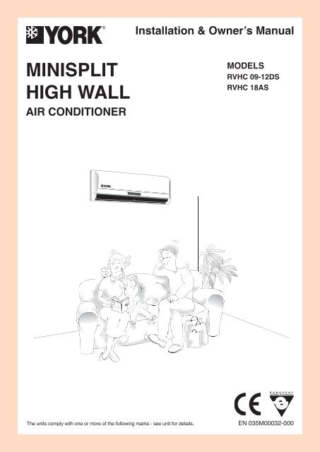
MINISPLIT HIGH WALL
MINISPLIT HIGH WALL
MINISPLIT HIGH WALL

Create successful ePaper yourself
Turn your PDF publications into a flip-book with our unique Google optimized e-Paper software.
CONTENTSSafety Precautions ................................................... 3Part Names ................................................................ 4Manual Operation ..................................................... 5How the Air Conditioner Works ............................... 5Optimal Operation .................................................... 6Preparation Before Installation ............................... 6Installation Procedure .............................................. 8Maintenance ............................................................ 14Please read this installationmanual carefully before startingthe installation. It will tell younecessary information.Operation Tips ........................................................ 15Troubleshooting Guide .......................................... 16Technical Specification .......................................... 17Declaration of Conformity ..................................... 19Quality POLICYWe will continuously strive to satisfyour customers with consistentreliability in product, service andsupport through superior quality,service culture and distinctivetechnology.SetOutdoorIndoorR410ARVHCxxDSAAAR / RVHCxxASAAARRVJCxxDS-AAR / RVJCxxAS-AARRVKCxxDS-AAR / RVKCxxAS-AARJ355-EN.indd 21/12/07 3:20:51 PM
REQUIRED TOOLS1. Screw driver 9. Manifold gauge2. Hexagonal wrench 10. Gas leak detector3. Torque wrench 11. Vacuum pump4. Spanner 12. Pipe clamp5. Reamer 13. Pipe cutter6. Hole core drill 14. Flare tool set7. Tape measure 15. Electrical circuit tester8. ThermometerEXTENDED PARTS1. Refrigarant PipeModels 07-09 12-18Liquid size 1/4 inch 1/4 inchGas size 3/8 inch 1/2 inch2. Pipe insulation material (Polyethylene foam 9 mm thick)3. Vinyl tape4. PuttySAFETY PRECAUTIONS• Please read this installation manual carefully before starting installation of the unit.• This air conditioning system contains refrigerant under pressure, rotating parts and electrical connection whichmay be dangerous and can cause injury. Installation and maintenance of this air conditioning system should onlybe carried out by trained and qualifi ed personnel.• After unpacking, please check the unit carefully for possible damage.• Before undertaking any work on the unit, make sure that the power supply has been disconnected.WARNING & CAUTIONSINSTALLATIONDo not store or unpack the unit in a wet area orexpose to rain or water.Do not install in a place where fl ammable gasmay leak.ENIt may cause the unit to short circuit and may result electricshocks or fi re.It may cause fi re.Do not conduct installation in wet area or in therain.This system is designed for domestic or residentialuse only.It is a high risk to cause the electrical shocks.If used in certain environments, such as a manufacturingworkplace, the equipment may not function efficiently.ENGLISH 3J355-EN.indd 31/12/07 3:20:51 PM
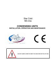
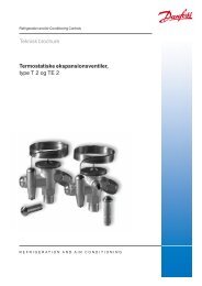
PART NAMESINDOOR UNITOUTDOOR UNITDISPLAY PANELSignal receptorAUTO TIMER DEF.FREQUENCY1 2 3 4 5■ INDOOR & OUTDOOR UNIT1 Front panel8 Remote controller signal2 Air inletreceiver3 Air fi lter9 Remote controller4 Air outlet0 Manual control button5 Horizontal air fl ow grille - Connecting pipe, drain hose6 Vertical air fl ow louver = Air inlet (side and rear)7 Display panel ~ Air outlet■ DISPLAY PANEL1 AUTO indicatorThis indicator illuminates when the air conditioner is in AUTOoperation.2 TIMER indicatorThis indicator illuminates when TIMER is set ON/OFF.3 DEFROST indicator (For Cooling & Heating models only)This indicator illuminates when the air conditioner startsdefrosting automatically or when the warm air control featureis activated in heating operation.4 TEMPERATURE indicatorA) Usually it displays the temperature settings.When change the setting temperature, this indicatorbegins to fl ash, and stops 20 seconds later.B) It displays the room temperature when the airconditioner is in FAN only operation.C) When the unit stops operation, it returns to originalfactory settings.D) Displays the malfunction code or protection code.5 FREQUENCY indicatorThis indicator appears only when the compressor is inoperation and indicates the current operating frequency.NOTEAll the pictures in this manual are for explanation purposeonly. They may be slightly different from the air conditioneryour purchased. The actual shape shall prevail.OPERATING TEMPERATUREMode Cooling Heating DryingTemperatureoperation operation operationRoom temperature 17°C-32°C 17°C-30°C 17°C-32°COutdoortemperature18°C-43°C -7°C-24°C 18°C-43°C4ENGLISHCAUTIONS1. If air conditioner is used outside of the above conditions,certain safety protection features may come into operationcause the unit to function abnormally.2. Room relative humidity less than 80%. If the air conditioneroperates in excess of this figure, the surface of the air conditionermay attract condensation. Please sets the vertical air flowlouver to its maximum angle (Vertically to the fl oor), andset <strong>HIGH</strong> fan mode.3. Optimum performance will be achieved within theseoperating temperature.J355-EN.indd 41/12/07 3:20:53 PM
OPTIMAL OPERATIONTo achieve optimal performance, please note the following:• Adjust the air fl ow direction correctly so that it is not directed on people.• Adjust the temperature to achieve the highest comfort level. Do not adjust the unit to excessive temperaturelevels.• Close doors and windows on COOL or HEAT modes, or performance may be reduced.• Use TIMER ON button on the remote controller to select a time you want to start your air conditioner.• Do not put any object near air inlet or air outlet, as the effi ciency of the air conditioner may be reduced and the airconditioner may stop running.• Clean the air fi lter periodically, otherwise cooling or heating performance may be reduced.• Do not operate unit with horizontal louver in closed position.PREPARATION BEFORE INSTALLATION• Before doing any work, check the interior power supply cord and the main breaker capacity are suffi cient and theinstallation area is suffi cient and complies with the requirements.• Check that the power supply available agrees with name plate voltage.• Electrical work, wiring and cables must be in compliance with national and local wiring codes and standard.• Do not use the extension cables. In the case extended cables are needed, use the terminal block.SELECTION OF THE LOCATION• Select a place which provides the space around the units as shown in the diagram below.INDOOR UNITOUTDOOR UNITModels 07 09 12 18A 12cm 12cm 12cm 12cmB 70cm 70cm 70cm 70cmC 12cm 12cm 12cm 12cmD 15cm 15cm 15cm 15cmModels 07 09 12 18A 30cm 30cm 30cm 30cmB 200cm 200cm 200cm 200cmC 60cm 60cm 60cm 60cmD 30cm 30cm 30cm 30cmCAUTION• Do not install in a place that cannot bear the weight of the unit.6ENGLISHJ355-EN.indd 61/12/07 3:20:56 PM
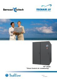
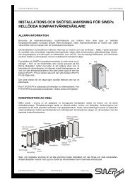
OUTDOOR UNIT PICTURESRVJC 07-12RVJC 18285750301.584331362335290125135351.2590694.5141.5560.1235530 110PARTS INSTALLATIONNumber Name of part Q’ty1 Installation plate 12 Clip anchor 83 Self-tapping screw A ST3.9X25 84ConnectingpipeassemblyLiquid side ø 6.35Gas sideø 9.53 (
OUTDOOR UNIT■ Fixing and Piping• Piping must be performed by qualifi ed personnel accordingto good refrigeration systems practices.• Piping materials and insulation materials must be ofrefrigerant quality.• Select the pipe diameters according to the size of unitand cut the pipe to design length by using pipe cutter.• Install the fl are nuts and fl are the end of the pipes.• Check that no foreign bodies are inside the piping.• Align the central of the connecting pipes and tightenthe fl are nut.• Fix piping with pipe clamps and check that any pipevibrations cannot be transmitted to the building structure.NOTES• Connect the pipe correctly.• Do not apply the excessive torque.• Use an appropriate bending tool to form curves andavoid over-tightening the refrigerant tubes.• To prevent heat loss, the two lines must be insulatedseparately.■ Maximum Piping LengthMODELSUnit size7 9 12 18(m) 10 15 18 20Refrigerant charge to be added per extra meterof piping length when more than 7.5 meters.MODELSUnit size7 9 12 18g/m 30 30 30 30■ Refrigerant piping connections(FLARE connections)To avoid alteration of unit capacities, check that pipinglengths and changes in elevation are kept to a strictminimum.Before connectiong the refrigerant lines, follow theprocedures below (if pre-charged connection lines arenot supplied):• Select copper pipe diameters according to the size ofunit to be installed.• Install the refrigeration lines, checking that no foreignbodies get inside the piping.• Install the fl are connectors and fl are the ends of thepipes.• Evacuate the piping. This operation, which should lastat least 15 minutes if there are large piping lengths andchanges in elevation, should be followed by a leak test.The suction line must have a 2% gradient up to thecompressor on horizontal sections.Where piping lengths are unusually long and include alarge number of oil traps, it may be necessary to adjustto compressor charge.10ENGLISHJ355-EN.indd 101/12/07 3:21:01 PM
■ WiringPrepare the power source for exclusive with the air conditioner.The supply voltage must comply with the rated voltage of the air conditioner: The plug socket shall be accessible afterinstallation.Remark: All the wiring must be based on the wiring nameplate which is shown on the model.CAUTIONS• Perform the wiring with suffi cient capacity. Installation places legally require a short circuit isolator to be attachedto prevent electrical shock.• Do not extend the power cable code by cutting.• Power voltage should be in the range of 90%~110% of rated voltage.• The plug of the air conditioner takes a grounding leg, and clients should use a grounding socket so that the airconditioner can be grounded effi ciently.• If the power cord is damaged, replacement should be conducted by qualifi ed technician or a serviceman.NOTERemark per EMC Directive 89/336/EECTo prevent fl icker impressions during the start of the compressor (technical process), following installation conditionsdo apply.1. The power connection for the air conditioner has to be done at the main power distribution.The distribution has to be of a low impedance, normally the required impedance reaches at a 32 A fusing point.2. No other equipment has to be connected with this power line.3. For detailed installation acceptance, please refer to your contract with the power supplier if restrictions do applyfor products like washing machines, air conditioner or electrical ovens.4. For power details of the air conditioner, refer to the rating plate of the product.5. For any question, contact your local dealer.CAUTIONS• Never modify the unit by removing any of the safety guards or by bypassing any of the safety interlock switches.• Connect the connecting cable correctly and connect the connecting cable to terminal as identifi ed with theirrespective marks.• Do not scratch the conductive core & inner insulator of power supply cables and do not deform or smash on thesurface of cables.■ Electrical ConnectionsAll electrical wiring and connections must comply with local codes and standards. Power supply cord and interconnectioncord used must not be lighter than Polychloroprene sheathed cord (245 IEC 57 or H05RN-F).Disconnecting device must have a contact separation of at least 3 mm.Models : 07-18Power supply220-240V/1Ph/50HzL N SIndoor UnitLNSOutdoor UnitFor correct installation, a proper ground connection must be made for unit.12ENGLISHJ355-EN.indd 121/12/07 3:21:03 PM
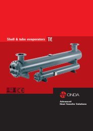
■ Wiring ConnectionModels : 07-18IndoorTerminal block of indoor unitOutdoorTerminal block of outdoor unitL N S L N S L N SCord clampTo outdoor unit7000/9000/18000Btu/h modelTo outdoor unit12000Btu/h modelTo indoor unit■ Electrical WorkModel Power Source Switch and Fuse rating Wiring size7000-12000 Btu/h18000 Btu/h220-240V ~ 50Hz220-230V ~ 60Hz220-240V ~ 50Hz220-230V ~ 60Hz25A f 1.5 mm 225A f 2.5 mm 2NOTEThe supply voltage must be consistent with the rate voltage of the air conditioner.EN■ Defrosting Operation (Available for heating only)1. Condition to start defrosting: Units will switch to defrostingmode when either of the following conditions is met.a. Unit has been running under T3 < 0ºC for 40 minutesand T3 < -3ºC for 3 minutes.b. Unit has been running at high temperature protectionmode* for 90 minutes. (*High temperature protectionmode: when coil temperature of indoor unit reaches55°C, outdoor unit will turn off external unit fan butstill keep compressor running).T3 (°C)2Starting Defrosting Mode under condition a.2. Condition to stop defrosting: Units will switch back toheating mode when either of the following conditionsis met.10-10 5 10 15 20 25 30 35 40 45 50TimeElapsed(min)a. Unit has been running at defrosting mode for 10minutes.b. T3 > 20°C-2Remark: T3 is coil temperature of outdoor units.-3-4-540 minHeating mode3 minDefrosting modeENGLISH 13J355-EN.indd 131/12/07 3:21:04 PM
MAINTENANCEHouseholdDrainCleanerNoWARNINGIt is necessary to stop the air conditioner and disconnect the powersupply before cleaning.■ Cleaning the indoor unit and remote controllerThinnerCAUTION• Use a dry cloth to wipe the indoor unit and remote controller.• A cloth dampened with cold water may be used on the indoor unit if itis very dirty.• The front panel of the indoor unit can be removed and cleaned withwater. Then wipe it with a dry cloth.• Do not use a chemically treated cloth or duster to clean the unit.• Do not use benzine, thinner, polishing powder, or similar solvents forcleaning. These may cause the plastic surface to crack or deform.Filter Handle■ Cleaning the air filterA clogged air fi lter reduces the cooling efficiency of this unit. Please cleanthe fi lter once every 2 weeks.1. Lift the indoor unit panel up to an angle until it stops with a clickingsound.2. Take hold of the handle of the air fi lter and lift it up slightly to take it outfrom the fi lter holder, then pull it downwards.3. Remove the AIR FILTER from the indoor unit.• Clean the AIR FILTER once two weeks.• Clean the AIR FILTER with a vacuum cleaner or water, then dry it upin cool place.4. Remove the Electrostatic Filter from its support frame as shown inthe Figure on the left (Not applicable to the units without electrostaticfi lter).Do not touch this Electrostatic Filter within 10 minutes after openingthe inlet grille, it may cause an electric shock.• Clean the Electrostatic Filter with mild detergent or water and dry inthe sunlight for two hours.• Before re-install the Electrostatic Filter, check whether the coronaline or support frame is damaged or not.5. Install the AIR FILTER back into position.6. Insert the upper portion of the AIR FILTER back into the unit takingcare that the left and right edges line up correctly and place fi lter intoposition.■ MaintenanceIf you plan to idle the unit for a long time, perform the following:(1) Operate the fan for about half a day to dry the inside of the unit.(2) Stop the air conditioner and disconnect power.Remove the batteries from the remote controller.(3) The outdoor unit requires periodic maintenance and cleaning. Do notattempt to do this yourself.Contact your dealer or servicer.■ Checks before operation• Check that the wiring is not broken off or disconnected.• Check that the air fi lter is installed.• Check if the air outlet or inlet is blocked after the air conditioner has notbeen used for a long time.CAUTION• Do not touch the metal parts of the unit when removing the fi lter.Injuries can occur when handling sharp metal edges.• Do not use water to clean inside the air conditioner.Exposure to water can destroy the insulation, leading to possibleelectric shock.• When cleaning the unit, fi rst make sure that the power and circuitbreaker are turned off.14ENGLISHJ355-EN.indd 141/12/07 3:21:05 PM
OPERATION TIPSThe following events may occur during normal operation.1. Protection of the air conditioner.Compressor protection• The compressor cannot restart for 3 minutes after it stops.Anti-cold air (Cooling and heating models only)• The unit is designed not to blow cold air on HEAT mode, when the indoor heat exchanger is in one of thefollowing three situations and the set temperature has not been reached.A) When heating has just starting.B) Defrosting.C) Low temperature heating.• The indoor or outdoor fan stop running when defrosting (Cooling and heating models only).Defrosting (Cooling and heating models only)• Frost may be generated on the outdoor unit during heat cycle when outdoor temperature is low and humidity ishigh resulting in lower heating effi ciency of the air conditioner.• During this condition air conditioner will stop heating operation and start defrosting automatically.• The time to defrost may vary from 4 to 10 minutes according to the outdoor temperature and the amount offrost buildup on the outdoor unit.2. A white mist coming out from the indoor unit.• A white mist may generate due to a large temperature difference between air inlet and air outlet on COOL modein an indoor environment that has a high relative humidity.• A white mist may generate due to moisture generated from defrosting process when the air conditioner restartsin HEAT mode operation after defrosting.3. Low noise of the air conditioner.• You may hear a low hissing sound when the compressor is running or has just stopped running.This sound is the sound of the refrigerant fl owing or coming to a stop.• You can also hear a low “squeak” sound when the compressor is running or has just stopped running. This is causedby heat expansion and cold contraction of the plastic parts in the unit when the temperature is changing.• A noise may be heard due to louver restoring to its original position when power is fi rst turned on.4. Dust is blown out from the indoor unit.This is a normal condition when the air conditioner has not been used for a long time or during fi rst use of theunit.EN5. A peculiar smell comes out from the indoor unit.This is caused by the indoor unit giving off smells permeated from building material, from furniture, or smoke.6. The air conditioner turns to FAN only mode from COOL or HEAT (for cooling and heating models only)mode.When indoor temperature reaches the temperature setting on air conditioner, the compressor will stop automatically,and the air conditioner turns to FAN only mode. The compressor will start again when the indoor temperature riseson COOL mode or falls on HEAT mode (for cooling and heating models only) to the set point.7. Dripping water may generate on the surface of the indoor unit when cooling in a high relatively humidity (relativehumidity higher than 80%). Adjust the horizontal louver to the maximum air outlet position and select <strong>HIGH</strong> fanspeed.8. Heating mode (For cooling and heating models only)The air conditioner draws in heat from the outdoor unit and releases it via the indoor unit during heating operation.When the outdoor temperature falls, heat drawn in by the air conditioner decreases accordingly. At the same time,heat loading of the air conditioner increases due to larger difference between indoor and outdoor temperature. If acomfortable temperature can not be achieved by the air conditioner, we suggest you use a supplementary heatingdevice.9. Auto-restart functionPower failure during operation will stop the unit completely. For the unit without Auto-restart feature, when thepower restores, the RUN indicator on the indoor unit starts fl ashing. To restart the operation, push the ON/OFFbutton on the remote controller. For the unit with Auto-restart feature, when the power restores, the unit restartsautomatically with all the previous settings preserved by the memory function.10. Lightning or a car wireless telephone operating nearby may cause the unit to malfunction.Disconnect the unit with power and then re-connect the unit with power again. Push the ON/OFF button on theremote controller to restart operation.ENGLISH 15J355-EN.indd 151/12/07 3:21:07 PM
TROUBLESHOOTING GUIDEProblem Probable cause RemedyA. The air conditioner doesnot run.B. The outdoor fan runs butthe compressor will notstart.C. There is insuffi cient heatingor cooling.D. The compressor runs continuously.E. The compressor starts butshuts down quickly.F. Clicking sound is heardfrom the air conditioner.1. Power failure.2. Fuse blown or circuit breaker open.3. Voltage is too low.4. Faulty contactor or relay.5. Electrical connections loose.6. Thermostat adjustment too low(in heating mode) or too high(in cooling mode).7. Faulty capacitor.8. Incorrect wiring, terminal loose.9. Pressure switch tripped.1. Motor winding cut or grounded.2. Faulty capacitor.1. There is a gas leak.2. Liquid and gas line insulatedtogether.3. The room was probably very hot(cool) when you started thesystem.1. Thermostat adjustment too low(in heating mode) or too high(in cooling mode).2. Faulty fan.3. Refrigerant charge too low, leak.4. Air or incondensables in refrigerantcircuit.1. Too much or too little refrigerant.2. Faulty compressor.3. Air or incondensables inrefrigerant circuit.4. Changeover valve damaged orblocked open (heat pump unit).In heating or cooling operation anyplastic parts may expand or shrink dueto a sudden temperature change in thisevent, a clicking sound may occur.1. Wait for power resume.2. Replace the fuse or reset thebreaker.3. Find the cause and fi x it.4. Replace the faulty component.5. Retighten the connection.6. Check thermostat setting.7. Find the cause then replacecapacitor.8. Check and retighten.9. Find the cause before reset.1. Check the wiring and thecompressor winding resistance.2. Find the cause then replacecapacitor.1. Remove charge, repair, evacuateand recharge.2. Insulate them separately.3. Wait while unit has enough timeto cool the room.1. Check thermostat setting.2. Check condenser air circulation.3. Find leak, repair and recharge.4. Remove charge, evacuate andrecharge.1. Remove charge, evacuate andrecharge.2. Determine the cause andreplace compressor.3. Remove charge, evacuate andrecharge.4. Replace it.In heating or cooling operation anyplastic parts may expand or shrinkdue to a sudden temperature changein this event, a clicking sound mayoccur.16ENGLISHJ355-EN.indd 161/12/07 3:21:09 PM
TECHNICAL SPECIFICATIONSTechnical Specifications : <strong>WALL</strong> TYPE (RVHC 09-12DS, 18AS) EVEREST INVERTER - 50 HzIndoorRVKCModelUnit RVKC09DS-AAA RVKC12DS-AAA RVKC18AS-AAAOutdoorRVJCUnit RVJC09DS-AAA RVJC12DS-AAA RVJC18AS-AAACooling CapacityBtu/h 9000(3500-11000) 12000(4400-14500) 18000(6500-22500)kW 2.6(1.0-3.2) 3.5(1.3-4.2) 5.3(1.9-6.6)Heating CapacityBtu/h 10000(3500-13800) 14000(4800-20500) 19000(7500-25000)kW 2.9(0.8-4.1) 4.1(1.4-6.0) 5.6(2.2-7.3)Power Supply V/Ph/Hz 220-240/1/50 220-240/1/50 220-240/1/50Power ConsumptionCooling W 810(260-1350) 1050(520-1600) 1720(850-2300)Heating W 810(330-1550) 1130(520-2050) 1790(1000-2500)COPCooling W/W 3.21 3.33 3.08Heating W/W 3.58 3.63 3.13Refrigerant TypeR-410ARefrigerant Charge g 1030 1200 1770Noise LevelIndoor UnitOutdoor UnitIndoor37 40 44dB(A)Outdoor 51 54 58Power Supply V/Ph/Hz 220-240/1/50FanAir flow (Hi/Me/Lo) m 3 /h 500/430/370 580/500/420 800/700/600Input Power W 35 44 55Running Current A 3.3(1.5-7.0) 5.1(2.7-8.5) 7.5(3.8-10.5)Height mm 250 265 292Dimension Width mm 710 790 920Depth mm 195 195 220Weight kg 7.5 9 13System Operation ControlWireless Control with LCD DisplayPower Supply V/Ph/Hz 220-240/1/50CompressorQty 1 1 1Compressor typeRotary InverterHeight mm 590 590 695Dimension Width mm 760 760 845Depth mm 285 285 335Weight kg 35 38 53PipingTypePipe SizeFlare+NutsSuction inch 3/8 1/2 1/2Liquid inch 1/4 1/4 1/4ENRemark : The above design and specifi cations are subject to change without prior notice for product improvement.ENGLISH 17J355-EN.indd 171/12/07 3:21:10 PM
TECHNICAL SPECIFICATIONSTechnical Specifications : Wall type Everest Inverter RVHC (RVKC-RVJC) R-410A 50Hz Rev.151206Set RVHC09DSAAAF RVHC12DSAAAFModelIndoor unit RVKC09DS-AAF RVKC12DS-AAFOutdoor Unit RVJC09DS-AAF RVJC012DS-AAFPower supply Ph-V-Hz 1, 220-240V~, 50Hz 1, 220-240V~, 50HzCapacity Btu/h 9,000(3,100~11,200) 12,000(3,800~14,700)CoolingInput W 660(300~1,100) 970(400~1,480)Rated current A 2.9(1.3~4.8) 4.3(1.8~6.5)Capacity Btu/h 10,000(3,300~12,300) 13,000(4,000~15,200)HeatingInput W 690(310~1,150) 950(390~1,460)Rated current A 3.0(1.4~5.0) 4.2(1.7~6.4)Moisture removal L/h 0.8 1.2Max. input consumption W 1,500 1,600Max. current A 8 8.5Starting current A 8 8.5PTC Heater (optional) W 85 85Type Rotary RotaryCapacity Btu/h 10,918 10,918Input W 855 855CompressorRated current (RLA) A 5.3 5.3Locked rotor Amp (LRA) A 8 8Protection Device Thermal protector Thermal protectorCapacitor µF No NoRefrigerant oil ml 480 480Input W 38 38Indoor fan motor Capacitor µF 1.5 1.5Speed (Hi/Med/Low) r/min 1,150/1,000/800 1,250/1,050/900a.Number of rows 2 2c.Fin spacing mm 1.3 1.3Indoor coil d.Fin type (code) hydrophilic aluminium hydrophilic aluminiume.Tube outside dia. and type mm Ø7, innergroove tube Ø7, innergroove tubef.Coil length×height×width mm (637+615)×(168+126)×(26.74+26.74) (637+615)×(168+126)×(26.74+26.74)Indoor air flow (Hi/Med/Low) m 3 /h 590/470/325 615/485/325Indoor noise level (Hi/Med/Low) dB(A) 41/35/30 43/37/30Dimension (W*H*D) mm 790*265*194 790*265*194Indoor unit Packing (W*H*D) mm 875*375*285 875*375*285Net/Gross weight Kg 8.5/10.5 9.0/11.0Input W 59 59Outdoor fan motor Capacitor µF 2.5 2.5Speed r/min 800/550 800/550a.Number of rows 2 2b.Tube pitch(a)×row pitch(b) mm 25.4x22 25.4x22Outdoor coilc.Fin spacing mm 1.4 1.4d.Fin type (code) hydrophilic aluminium hydrophilic aluminiume.Tube outside dia. and type mm Ø9.53, innergroove tube Ø9.53, innergroove tubef.Coil length×height×width mm 620×558.8×44 620×558.8×44Outdoor air flow m 3 /h 1,650/1,060 1,650/1,060Outdoor noise level dB(A) 52 54Dimension (W*H*D) mm 760*590*285 760*590*285Outdoor unit Packing (W*H*D) mm 887*655*355 887*655*355Net/Gross weight Kg 40.5/43 40.5/43Refrigerant type R-410A g 1,230 1,230Liquid side/Gas side mm Ø6.35/Ø9.53 Ø6.35/Ø12.7Refrigerant piping Max. refrigerant pipe length m 12 12Max. difference in level m 5 5Application area m 2 16-24 20-30Qty’per 20’ /40’ /40’HQ 92/184/225 92/184/225Remark : The above design and specifi cations are subject to change without prior notice for product improvement.18ENGLISHJ355-EN.indd 181/12/07 3:21:11 PM
TECHNICAL SPECIFICATIONSTechnical Specifications : High Wall RVHC09-18 (Everest Inverter R-410A MEPS) : 50Hz Rev.00Set RVHC09DSAAAF-II RVHC12DSAAAF-II RVHC18ASAAAA-IIModelIndoor unit RVKC09DS-AAF-II RVKC12DS-AAF-II RVKC18AS-AAA-IIOutdoor unit RVJC09DS-AAF-II RVJC12DS-AAF-II RVJC18AS-AAA-IIPower supply Ph-V-Hz 1, 220-240V~, 50Hz 1, 220-240V~, 50Hz 1, 220-240V~, 50HzBtu/h 8,987(3,100~11,200) 11,539(3,800~14,700) 15,958(6,500-22,500)CapacitykW 2.63(0.91~3.29) 3.38(1.11~4.31) 4.68(1.90-6.60)Coolingkcal/h 2,265(781~2,822) 2,908(958~3,704) 4,021(1,638~5,670)Input W 660(300~1,100) 970(400~1,480) 1,701(850-2,300)Rated current A 2.97(1.3~4.8) 4.26(1.8~6.5) 7.5(3.8-10.5)EER W/W 3.84 3.45 2.8Btu/h 9,723(3,300~12,300) 12,361(4,000~15,200) 16,313(7,500-25,000)CapacitykW 2.850(0.967~3.605) 3.623(1.172~4.455) 4.781(2.198-7.327)Heatingkcal/h 2,450(832~3,100) 3,115(1,008~3,830) 4,111(1,890~6,300)Input W 690(310~1,150) 950(390~1,460) 1,739(1,000-2,500)Rated current A 2.95(1.4~5.0) 4.32(1.7~6.4) 7.9(4.2-11.1)COP W/W 4.2 3.64 2.8Max. input consumption W 2,400 3,000 4,000Max. current A 12 15 18Starting current A 3.8 4.5 9.0Type Rotary Rotary RotaryInput W 680 680 1,630Rated current (RLA) A 4.7 4.7 10.95Compressor Locked rotor Amp (LRA) A 10 10 55Thermal protectorInternalCapacitor µF No No NoRefrigerant oil ml 370 370 750Input W 38 38 55Indoor fan motorCurrent A 0.17 0.17 0.25Capacitor µF 1.2 1.5 1.5Speed (Hi/Mi/Lo) r/min 1,360/1,100/880 1,300/1,000/800 1,140/1,060/980Number of rows 2 2 2Fin spacing mm 1.3 1.3 1.3Indoor coilFin typeHydrophilic aluminiumTube outside dia. mm Ø7Tube MaterialInnergroove tubeCoil length×height×width mm 538×252×26.74 637×294×26.74 806×232×26.74Indoor air flow (Hi/Mi/Lo) m 3 /h 500/430/370 580/500/420 800/700/600Indoor noise level (Hi/Mi/Lo) dB(A) 39/35/29 41/36/30 44/40/37Dimension (W*H*D) mm 790×265×194 790×265×194 920×293×224Indoor unitPacking (W*H*D) mm 875×375×285 875×375×285 1,020×320×385Net/Gross weight Kg 8.5/10.5 9.0/11.0 13/15Input W 59 59 130Outdoor fan motorCurrent A 0.27 0.27 0.6Capacitor µF 2.5 2.5 3Speed r/min 800 900 800Number of rows 1.5 2 2Fin spacing mm 1.5 1.5 1.6Outdoor coilFin typeHydrophilic aluminiumTube outside dia. mm Ø9.53Tube MaterialInnergroove tubeCoil length×height×width mm 680×550×44 680×550×44 803×635×44Outdoor air flow m 3 /h 1,700 1,900 2,500Outdoor noise level dB(A) 52 52 58Dimension (W*H*D) mm 760×590×285 760×590×285 845×695×335Outdoor unit Packing (W*H*D) mm 887×655×355 887×655×355 970×770×395Net/Gross weight Kg 40.5/43 40.5/43 53/67Refrigerant type R410A g 1,230 1,230 1,770Refrigerant piping Liquid side/Gas side mm Ø6.35/Ø9.53 Ø6.35/Ø12.7 Ø6.35/Ø12.7ENRemark : The above design and specifi cations are subject to change without prior notice for product improvement.ENGLISH 19J355-EN.indd 191/12/07 3:21:13 PM
DECLARATION OF CONFORMITYType of EquipmentBrand NameType DesignationApplication of CouncilDirective (s)DECLARATION OF CONFORMITYAir ConditionersYORKHAEA-HADA07/09/12FS, HAEB-HADB07/09/12FS, HAEC-HADC07/09/12FS, HAKA-HAJA07/09/12FS,HAKB-HAJB07/09/12FS, HAKC-HAJC07/09/12FS, HEEB-HEDB07/09/12/18/24/30FS,HEKB-HEJB07/09/12/18/21/24/30FS, HLEA-HLDA07/09/12/18/24FS, HLCA-HLHA24/28/FS,HMEA09MC/MD/ME, HMDA18MC, HMDA21MD, HMDA27ME, HMKB09MC/MD/ME/MF,HMKB12MD/MF, HMJB18MC, HMJB21MD, HMJB27ME, HMJB30MF, HRKB09AB/AG/AH,HRKB12AG, HRJB18AB, HRJB21AG, HRJB27AH, HRKA09AB, HRJA18AB,HSKB-HSJB07/09/12/18/24FS, HTEA-HTDA18/21/24/30FS, HVKA-HVJA09/12/21/24AS,HVKC-HVJC07/09/12DS, HVKC-HVJC18AS, PECA09/12FD,PECB09/12/14FS, PESA09/12FD, PESB09/12/14FS, PLCA09FC/FD, PLCB09FC/FD,PLSA09FC/FD, PLSB09FC/FDMACC-MAHC07/09/12/18/24FS, MECB-MEHB07/09/12/18/24FS, MLCA-MLHA07/09/12/18/24FS,MLCB-MLHB07/09/12/18/24FS, RACC-RAHC07/09/12/18/24/28FS, RLCB-RLHB07/09/12/18/24/28FS,RLCA-RLHA07/09/12/18/24/30FS, RTCA-RTHA/18/24/30RS/OS,EMC Directive 89/336/EEC, Low Voltage Directive 73/23/EEC and Machine Safety Directive: MSD 98/37/CEThe following harmonized standards have been applied:Standard (s)EN 60335-2-40/A1:2000EN 60335-2-40/A1:2000EN 55014-1:2000/A2:2002EN 55014-2:1997/A1:2001EN 55022:1998/A1:2000EN 61000-3-2:2000EN 61000-3-3:1995/A1:2001EN 61000-3-11:2000EN 60825EN 60335-1:1994+A11:1995+A1, A12:1996+A13, A14:1998+A15, A2:2000+A16:2001EN 60335-2-40:1997+A1:2000EN 55014-1:1993+A1:1997/A2:1999EN 55104-2:1997EN 61000-3-2:1995/A1:1998/A2:1998EN 61000-3-2:1995/A14:2000EN 61000-3-3:1995EN 60335-2-40:2003EN 50366:2003EN 60335-1:2002 +A11EN 55014-1/A2:2002EN 55104-2/A1:2201The product complies with the harmonized European safety standards and harmonized EMC standards listed above.We have internal production control system that ensures compliance between the manufacturer products and the technical documentation.The product is CE mark.We declare under our sold responsibility that the equipment follows the provisions Of the Directives stated above.Authorized Representative:CM ChoiShipping ManagerYORK International (Northern Asia) Ltd.15/F., Tower II, World Trade Square, 123 Hoi Bun Road, Kwun Tong, Kowloon, Hong KongTelephone: (852) 2331 9286 Fax: (852) 2331 9840Technical Service Division: Telephone: (852) 2331 9286 Fax: (852) 2304 0068INSTALLATION, REMOVAL AND DISPOSALThis product contains refrigerant under pressure, rotating parts, and electrical connections which may be a danger and cause injury!All work must only be carried out by competent persons using suitable protective clothing and safety precautions.Read the ManualRisk of electricshockUnit is remotely controlled andmay start without warning1. Isolate all sources of electrical supply to the unit including any control system supplies switched by the unit. Ensure that all points of electrical and gasisolation are secured in the OFF position. The supply cables and gas pipework may then be disconnected and removed. For points of connection referto unit installation instructions.2. Remove all refrigerant from each system of the unit into a suitable container using a refrigerant reclaim or recovery unit. This refrigerant may then bereused, if appropriate, or returned to the manufacturer for disposal. Under No circumstances should refrigerant be vented to atmosphere. Whereappropriate, drain the refrigerant oil from each system into a suitable container and dispose of according to local laws and regulations governing disposalof oily wastes.3. Packaged unit can generally be removed in one piece after disconnection as above. Any fi xing down bolts should be removed and then unit lifted fromposition using the points provided and equipment of adequate lifting capacity. Reference MUST be made to the unit installation instructions for unit weightand correct methods of lifting. Note that any residual or spilt refrigerant oil should be mopped up and disposed of as described above.4. After removal from position the unit parts may be disposed of according to local laws and regulations.J355-EN.indd 201/12/07 3:21:14 PM