AN/PRC-150(C) - Harris Corporation
AN/PRC-150(C) - Harris Corporation
AN/PRC-150(C) - Harris Corporation

Create successful ePaper yourself
Turn your PDF publications into a flip-book with our unique Google optimized e-Paper software.
4R/T Specifications ChartR/T SpecificationsFunctionGENERALSpecificationFrequency RangeFrequency StabilityRadio Frequency (RF) Input/Output (I/O) ImpedancePower InputReceiver SensitivityAudio OutputImage RejectionIntermediate Frequency (IF)RejectionInternally Generated SpuriousSignalsTransmitter Power OutputCarrier SuppressionUndesired Sideband RejectionTransmit IntermodulationDistortionReceiver Spurious ResponsesAudio InputDimensions (with battery box)Weight (with battery box and twoBB-590/U batteries)Single Sideband (SSB): Upper Sideband (USB) and Lower Sideband (LSB), and Amplitude ModulationEquivalent (AME) Modes: 1.6 MHz to 29.99999 megahertz, (MHz) in 100 Hz steps from the front paneland in 10 Hz steps from the REMOTE port. Frequency Modulation (FM) Modes: 20 MHz to 59.99999MHz in 100 Hz steps from the front panel and in 10 Hz steps from the REMOTE port.1.0 x 10-6 for not less than 30 days50 ohms+26 VDC nominal; normal operations from +23 to +32 VDC, +34.5 VDC Li-ION; when battery voltagereaches 21 VDC, the radio shuts down. Reduced power output by -6 dB of full power 21 VDC to 23 VDC(If power output is set -6 dB of full power.-113 dBm for 10 dB Signal + Noise + Distortion/Noise + Distortion (SINAD) ([SSB], 2.7 kHz IFBandwidth [BW] -98 dBm for 10 dB SINAD AME, 6.0 kHz BW, 30% modulation -117 dBm for 10dB SINAD (Continuous Wave [CW], 0.25 kHz BW -107 dBm for 10 dB SINAD (FM, 22 kHz, 8 kHzdeviation)≥15 mW into a 1000-ohm loadFirst Intermediate Frequency (IF): >80 dB Second IF Image: >60 dBFirst IF: >80 dB Second IF: >70 dB 1.6 to 2.4 MHz, 80 dB 2.4 to 60 MHzBelow -112 dBm on 99% of 3 kHz USB/LSB channels over 1.6 to 60 MHzHigh: 20 W Peak Envelope Power (PEP)/Average SSB; 10 W Average FM Medium: 5 W PEP/AverageSSB or FM Low: 1 W PEP/Average SSB or FM>60 dB below PEP>60 dB below PEP1.6 to 29.99999 MHz: -24 dB (3rd order or higher) 30 MHz to 59.99999 MHz: -18 dB(3rd order or higher)Down at least 55 dB when 2.5% to 30% from center frequency1.5 mV rms with <strong>150</strong>-ohm source impedance10.43 W x 13.31 D x 3.2 H in (26.5 W x 33.8 D x 8.1 H cm)17.2 lbs (7.8 kg)Note: BA-5390/U and BA-5590/U batteries are primary cells.Falcon II ® <strong>AN</strong>/<strong>PRC</strong>-<strong>150</strong>(C) Application Guide
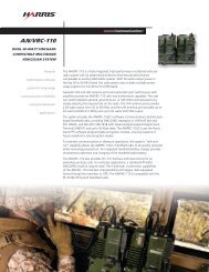
6System Interconnect DiagramsRF-5800H-V002<strong>AN</strong>/<strong>PRC</strong>-<strong>150</strong>M<strong>AN</strong>PACK RADIOAUDIO CABLE(10497-5036-01)COAXIAL CABLEASSEMBLY(10497-5015-01)H<strong>AN</strong>DSET(H-250/U)(10075-1399)RF-5833H-PA002POWER AMPLIFIERPA CONTROL CABLE(10535-0720-B17)RF-5833H-PA002POWER AMPLIFIER(REAR VIEW)10181-9823-XXX (RF-382)*or12020-1460-AXXX (RF-5382)*RF-5382WorRF-382ATO GROUNDLPF CABLEASSEMBLY10497-0363-01F<strong>AN</strong> POWERCABLETO VHF<strong>AN</strong>TENNADC POWER CABLE(10181-9826-020)TO VEHICLEALTERNATOR/BATTERYSYSTEM10181-9824-###**NOTE: PART NUMBERSVARY WITH INSTALLATION*COUPLER PURCHASEDSEPARATELYFalcon II ® <strong>AN</strong>/<strong>PRC</strong>-<strong>150</strong>(C) Application Guide
System Interconnect Diagrams9H<strong>AN</strong>DSET(H-250/U)(10075-1399)SPEAKERRF-5980-SA001RF-5800H-V006SPEAKERPOWER CABLE10535-6708-AXXX24V DC POWER SOURCE10535-0707-AXXX<strong>AN</strong>/<strong>PRC</strong>-<strong>150</strong> M<strong>AN</strong>PACK RADIOR/T TO DISTRIBUTIONP<strong>AN</strong>EL(12045-5700-A30)28 VDCVEHICULARPOWERDC POWERCABLE ASSEMBLY(10181-9826-020)RF-5211VSM-052SHOCK MOUNTN TO BNC CABLE(10369-7211-015)(REAR VIEW)RF-5382H-CU001<strong>AN</strong>TENNA COUPLERRF-5211VSM-052SHOCK MOUNT/DISTRIBUTION MODULE(REAR VIEW)COUPLER CONTROLCABLE(12020-1460-A020)(FRONT VIEW)RF-5382H-CU001<strong>AN</strong>TENNA COUPLERHF<strong>AN</strong>TENNA*COUPLER PURCHASEDSEPARATELYTOGROUNDNOTES:ENSURE THAT THE VEHICULARSHOCK MOUNTS ARE GROUNDEDPER INSTRUCTIONS GIVEN IN M<strong>AN</strong>UAL.HF <strong>AN</strong>TENNAFalcon II ® <strong>AN</strong>/<strong>PRC</strong>-<strong>150</strong>(C) Application Guide
10System Interconnect DiagramsRF-5800H-B001<strong>AN</strong>/<strong>PRC</strong>-<strong>150</strong>M<strong>AN</strong>PACK RADIOAUDIO CABLE(10497-5036-01)COAXIAL CABLEASSEMBLY(10497-5015-01)H<strong>AN</strong>DSET(H-250/U)(10075-1399)PA CONTROL CABLE(10535-0720-B17)RF-5833H-PA001POWER AMPLIFIERRF-5833H-PA001POWER AMPLIFIER(REAR VIEW)10181-9823-XXX (RF-382)*or12020-1460-AXXX (RF-5382)*RF-5382WorRF-382ATO GROUNDTO VHF<strong>AN</strong>TENNAF<strong>AN</strong> POWERCABLEDC POWER CABLE(10181-9833-004)10181-9624-###**NOTE: PART NUMBERSVARY WITH INSTALLATION*COUPLER <strong>AN</strong>D CABLESPURCHASED SEPARATELYTO GROUNDAC POWER CABLE(10181-9831-009)TO AC POWER90-300 VAC, 47-400 HzFalcon II ® <strong>AN</strong>/<strong>PRC</strong>-<strong>150</strong>(C) Application Guide
System Interconnect Diagrams11RF-5800H-B002<strong>AN</strong>/<strong>PRC</strong>-<strong>150</strong>M<strong>AN</strong>PACK RADIOAUDIO CABLE(10497-5036-01)COAXIAL CABLEASSEMBLY(10497-5015-01)H<strong>AN</strong>DSET(H-250/U)(10075-1399)PA CONTROL CABLE(10535-0720-B17)RF-5833H-PA004POWER AMPLIFIERRF-5833H-PA002POWER AMPLIFIER(REAR VIEW)10181-9823-XXX (RF-382)*or12020-1460-AXXX (RF-5382)*TOGROUNDRF-5382orRF-382F<strong>AN</strong> POWERCABLEDC POWER CABLE(10181-9833-004)TOVHF<strong>AN</strong>TENNARF-382A<strong>AN</strong>TENNA COUPLER(OPTIONAL)10181-9824-###*TO GROUNDAC POWER CABLE(10181-9831-009)TO AC POWER90-300 VAC, 47-400 Hz*NOTE: PART NUMBERSVARY WITH INSTALLATION*COUPLER PURCHASEDSEPARATELYFalcon II ® <strong>AN</strong>/<strong>PRC</strong>-<strong>150</strong>(C) Application Guide
12System Interconnect DiagramsSPEAKERRF-5980-SA001RF-5800H-B003H<strong>AN</strong>DSET(H-250/U)(10075-1399)SPEAKER CABLEASSEMBLY(10535-0707)<strong>AN</strong>/<strong>PRC</strong>-<strong>150</strong>M<strong>AN</strong>PACK RADIOTO GROUNDR/T-PACOAX CABLE(10181-9821)SPEAKER POWERCABLE ASSY(10535-0706)R/T-PACONTROL CABLE(10535-0720)RF-5834H-PA-400POWER AMPLIFIERRF-382A<strong>AN</strong>TENNA COUPLERPA TO COUPLERCONTROL CABLE(10181-9823)TO GROUNDPA TO COUPLERRF COAX CABLE(10181-9825 OR10181-9824)TO AC POWERAC POWERCABLE(10181-9831)DC POWERINTERCONNECT CABLE(10181-9834)115/230 VAC,47-400 Hz1825 WATTS TOTALDC POWERINTERCONNECT CABLE(10181-9836)TO AC POWERAC POWERCABLE(10181-9831)TO GROUND*COUPLER PURCHASEDSEPARATELYNOTE: BE SURE TO GROUND SYSTEM FROM THEGROUNDING STUD PROVIDED ON THE SYSTEM MOUNT.Falcon II ® <strong>AN</strong>/<strong>PRC</strong>-<strong>150</strong>(C) Application Guide
System Interconnect Diagrams13SPEAKERRF-5980-SA001RF-5800H-B004H<strong>AN</strong>DSET(H-250/U)(10075-1399)SPEAKER CABLEASSEMBLY(10535-0707)<strong>AN</strong>/<strong>PRC</strong>-<strong>150</strong>M<strong>AN</strong>PACKRADIOTO GROUNDR/T-PACONTROL CABLE(10535-0720)R/T-PACOAX CABLE(10181-9821)RF-382 or RF-5382SPEAKER POWERCABLE ASSY(10535-0706)RF-5832H-PAPOWER AMPLIFIERPA-COUPLERCONTROL CABLE10181-9823-XXX or12020-1460-AXXX(RF-5382)TO GROUNDPA TO COUPLERRF COAX CABLE(10181-9825 OR 10181-9824)RF-5051PS-125POWER SUPPLYPA DC POWERINTERCONNECT CABLE(10181-9833)TO ACPOWERAC POWERCABLE(10181-9831)*COUPLER <strong>AN</strong>D CABLESPURCHASED SEPARATELYTO GROUNDFalcon II ® <strong>AN</strong>/<strong>PRC</strong>-<strong>150</strong>(C) Application Guide
Vehicular Systems15<strong>150</strong>-Watt HF/VHF Vehicular AdapterThe RF-5800H-V001 includes:Product Number Product Name Qty10497-0200-01 PA Vehicular Shock Mount 1RF-5833H-PA001 <strong>150</strong>-Watt PA 110497-5020-A08 Coax Cable Assembly 110497-5036-01 Audio Cable Assembly 110181-9826-020 Power Cable Assembly 110515-0122-4200 <strong>150</strong>-Watt Installation Manual 110535-0720-B17 Control Cable Assembly (PA-RT) 17147-1167-3 Ground Strap 1RF-5800H-V001The RF-5800H-V001 provides the equipment complement necessaryto transform the transceiver into a <strong>150</strong>-watt PEP/Average HF-SSB(60-watt VHF-FM) vehicular system. The adapter facilitates rapidconversion to a manportable configuration.Color: Green.Note: The Receiver/Transmitter is not included and must beordered separately.Features»»USB, LSB, CW, AME, and FM operation from 1.6-60 MHzfrequency band»»Solid-state, broadband RF power amplifier»»Built-in loudspeaker»»Separate HF and VHF RF outputs»»Small size and weight»»Fully ruggedized per MIL-STD-810F»»Heatsink and fan for continuous keydown»»Overload protection»»Operates from 26.5 VDC»»Built-In Test (BIT)Falcon II ® <strong>AN</strong>/<strong>PRC</strong>-<strong>150</strong>(C) Application Guide
16Vehicular Systems<strong>150</strong>-Watt HF/VHF Vehicular Adapter withCollocation FilteringThe RF-5800H-V002 includes:Product Number Product Name Qty10497-0200-01 PA vehicular shock mount 1RF-5833H-PA004 <strong>150</strong>-Watt PA with RF-5245 110497-0360-02 25 MHz Low Pass Filter 110497-5020-A08 Coax Cable Assembly 110497-5036-01 Audio Cable Assembly 110181-9826-020 Power Cable Assembly 110515-0122-4200 <strong>150</strong>-Watt Installation Manual 110535-0720-B17 Control Cable Assembly (PA-RT) 17147-1167-3 Ground Strap 1RF-5800H-V002The RF-5800H-V002 provides the equipment complement necessaryto transform the transceiver to a <strong>150</strong>-watt PEP/Average HF-SSB(60-watt VHF-FM) vehicular system. The adapter includes the RF-5245 Pre/postselector and an HF low-pass filter for the attenuation ofunwanted signals in collocated applications. The adapter facilitatesthe rapid conversion to a manportable configuration.Color: Green.Note: The Receiver/Transmitter is not included and must beordered separately.Features»»USB, LSB, CW, AME, and FM operation from 1.6-60 MHzfrequency band»»Solid-state, broadband RF power amplifier»»Built-in loudspeaker»»Built-in pre/postselector provides attenuation of unwantedsignals at frequencies 10% or greater from the carrier»»Integral low-pass filter provides additional attenuation ofunwanted signals at frequencies greater than 35 MHz»»Separate HF and VHF RF outputs»»Small size and weight»»Fully ruggedized per MIL-STD-810F»»Heatsink and fan for continuous keydown»»Operates from 26.5 VDC400-Watt HF-SSB Vehicular AdapterRF-5800H-V003The RF-5800H-V003 provides the equipment complement necessaryto transform the transceiver into a 400-watt PEP/Average HF-SSBvehicular system. The adapter facilitates rapid conversion to amanportable configuration. Configuration is for HF communicationsonly and will not operate in the 30 to 60 MHz frequency band.Color: Green.Note: The Receiver/Transmitter is not included and must beordered separately.Features»»SSB, LSB, CW and AME operation in the 1.6-30 MHz HFfrequency band»»Solid-state, broadband RF power amplifier»»Small size and weight»»Fully ruggedized per MIL-STD-810F»»Overload protection»»Operates from 26.5 VDC nominal»»Built-In Test (BIT)Falcon II ® <strong>AN</strong>/<strong>PRC</strong>-<strong>150</strong>(C) Application Guide
Vehicular Systems17The RF-5800H-V003 includes:Product Number Product Name QtyRF-5834H-PA001 400-Watt Power Amplifier 110181-5074-03 PA Vehicular Shock Mount 1RF-5211VSM R/T Vehicular Shock Mount 110181-9821-020 Coax Cable Assembly 110181-9828-020 Power Cable Assembly 110515-0123-4200 400-Watt Installation Manual 110535-0720-A020 Control Cable Assembly, PA-RT 17147-1167-3 Ground Strap 1<strong>AN</strong>/VRC-104(V)3 <strong>150</strong>-WattVehicular SystemRF-5800H-V002The <strong>AN</strong>/VRC-104(V)3 provides the equipment complementnecessary to transform the transceiver to a <strong>150</strong>-watt PEP/Average HF-SSB (60-watt VHF-FM) vehicular system. The adapterincludes the RF-5245 Pre/postselector and an HF low-pass filterfor the attenuation of unwanted signals in collocated applications.The adapter facilitates the rapid conversion to a manportableconfiguration. This system includes everything needed for aHumvee installation including antenna and coupler.Features»»<strong>150</strong>-watt PEP/ Average»»1.6 to 30 MHz»»30 to 60 MHz FM Operation»»Internal ALE and 3rdGeneration ALE»»Internal High Speed Modem»»Internal Type I Encryption»»Internal Digital Voice»»26.6 VDC Operation»»See System InterconnectDiagrams for equipment listPart Number Description10181-5178-06 Mounting Kit, Humvee Ant10497-0200-01Shk Mt Assy, RF-5073 Vm, CARC Green38310535-0960-01 Ancillary Items, RF-5800H-V00110540-0900-01Ancillary Items, <strong>150</strong> Watt Vehicle Sys(20 Ft Cplr Cbl)11080-3970-01DC Switch Assy, <strong>150</strong>w,CARC Green 383RF-3120-AT360 Antenna, 35 Ft. Locking, Tilt, Hv, GreenRF-382A-15RF-382A-15, CARC GreenRF-384VM-03 Shock Mount, O.D. CARCRF-5833H-PA004 Falcon II <strong>150</strong>W PA W/Cosit & PrepostColor: Green.Note: The Receiver/Transmitter is not included and must beordered separately.Falcon II ® <strong>AN</strong>/<strong>PRC</strong>-<strong>150</strong>(C) Application Guide
18Base SystemsBase Systems125-Watt HF-SSB Base Station AdapterRF-5800H-B004The RF-5800H-B004 provides the equipment complement necessaryto transform the transceiver to a 125-watt PEP/Average HF-SSBbase station system. The adapter facilitates the rapid conversion to amanportable configuration. A U.S. power connector (NEMA5-15P) issupplied as the standard AC power connector.The RF-5800H-B004 includes:Product Number Product Name Qty10558-2000-04 Base Station Mount 1RF-5832H-PA101 Falcon II 125-Watt PA 1RF-5051-PS001 Power Supply 1RF-5980-SA001 Loudspeaker 110535-0707-A003 Speaker Audio Cable Assembly 110535-0706-A015 Speaker Power Cable Assembly 110181-9821-015 Coax Cable Assembly 110181-9833-004 DC Power Cable Assembly 110515-0124-4200 125-Watt Installation Manual 110535-0720-A015 Control Cable Assembly, PA-RT 110181-9831-009AC Power Cable (NEMA 5-15P)P/O RF-5051-PS001110400-1136-A006 Ground Strap 1Note: Configuration is for HF communications only and will notoperate in the 30 to 60 MHz frequency band.Color: Green.Note: The Receiver/Transmitter is not included and must beordered separately.Features»»USB, LSB, CW, and AME operation in the 1.6-30 MHz HFfrequency band»»Solid-state, broadband RF power amplifier»»Small size and weight»»Integrated loudspeaker»»Fully ruggedized per MIL-STD-810F»»Overload protection»»115 or 230 VAC, 47-400 Hz power operation»»Built-In Test (BIT)»»Removable Radio TrayFalcon II ® <strong>AN</strong>/<strong>PRC</strong>-<strong>150</strong>(C) Application Guide
20Base Systems<strong>150</strong>-Watt HF/VHF Base Station Adapter withCollocation FilteringRF-5800H-B002The RF-5800H-B002 provides the equipment complement necessaryto transform the transceiver to a <strong>150</strong>-watt PEP/Average HF-SSB(60-watt VHF-FM) base station system. The adapter includes the RF-5245 Pre/postselector and an HF low-pass filter for the attenuation ofunwanted signals in collocated applications. The adapter facilitatesrapid conversion to a manportable configuration.Color: Green.Note: The Receiver/Transmitter and the UK or EU Cord are notincluded and must be ordered separately.Features»»USB, LSB, CW, AME, and FM operation from 1.6-60 MHzfrequency band»»Solid-state, broadband RF power amplifier»»Built-in loudspeaker»»Built-in pre/postselector provides attenuation of unwantedsignals at frequencies 10% or greater from the carrier»»Integral low-pass filter provides additional attenuation ofunwanted signals at frequencies greater than 35 MHz»»Separate HF and VHF RF outputs»»Small size and weight»»Fully ruggedized per MIL-STD-810F»»Heatsink fan for continuous keydown»»Overload protection»»115 or 230 VAC, 47-400 Hz power operation»»Built-In Test (BIT)The RF-5800H-B002 includes:Product Number Product Name Qty10497-0850-03 Stack Bracket 1RF-5833H-PA002 <strong>150</strong>-Watt PA with RF-5245 110497-0360-02 25 MHz Low Pass Filter 110299-5051-03 Power Supply 110497-5015-01 Coax Cable Assembly 110497-5036-01 Audio Cable Assembly 110515-0122-4200 <strong>150</strong>-Watt Installation Manual 110535-0720-B17Control Cable Assembly(PA/RT)110181-9833-004 DC Power Cable Assembly 110181-9831-009AC Power Cable (NEMA 5-15P)P/O RF-5051-PS001110400-1136-A006 Ground Strap 1Falcon II ® <strong>AN</strong>/<strong>PRC</strong>-<strong>150</strong>(C) Application Guide
Base Systems21400-Watt HF-SSB Base Station AdapterFeatures»»USB, LSB, CW, and AME operation in the 1.6-30 MHz HFfrequency band»»Solid-state, broadband RF power amplifier»»Small size and weight»»Integrated loudspeaker»»Fully ruggedized per MIL-STD-810F»»Overload protection»»115 or 230 VAC, 47-400 Hz power operation»»Built-In Test (BIT)RF-5800H-B003The RF-5800H-B003 provides the equipment complement necessaryto transform the transceiver to a 400-watt PEP/Average HF-SSBbase station system. The adapter facilitates the rapid conversion to amanportable configuration.Color: Green.Note: The Receiver/Transmitter and the UK or EU Cord are notincluded and must be ordered separately.The RF-5800H-B003 includes:Product Number Product Name QtyRF-5834H-PA001 400-Watt Power Amplifier 110558-2000-03 Base Station Mount 1RF-5051-PS001 AC Power Supply 2RF-5980-SA001 Tactical Loudspeaker 110535-0707-A003 Speaker Audio Cable Assembly 110535-0706-A015 Speaker Power Cable Assembly 110181-9821-015 Coax Cable Assembly 110181-9834-004 DC Power Cable Assembly 110515-0123-4200 400-Watt Installation Manual 110535-0720-A015Control Cable Assembly (RT toPA)110400-1136-A12 Ground Strap 210400-1136-A30 Ground Strap 210400-1136-A48 Ground Strap 1Note: Configuration is for HF communications only and will notoperate in the 30 to 60 MHz frequency band.Falcon II ® <strong>AN</strong>/<strong>PRC</strong>-<strong>150</strong>(C) Application Guide
22Transportable SystemsTransportable Systems125-Watt HF-SSB Mini-Transit Case AdapterRF-5800H-TM004The RF-5800H-TM004 provides the equipment complementnecessary to transform the transceiver to a 125-watt PEP/AverageHF-SSB Mini-Transit Case system. The transit case adapterprovides the durability of a base station with the transport flexibilityand portability of a vehicular system. A clip on each corner ofthe case can be used to clamp the cases together to create aportable rack. If the cases are installed in a shelter and the systemneeds to be removed, it is easy to separate the cases from eachother. Storage of all interface cables in the cases facilitates easyequipment deployment. The adapter facilitates the rapid conversionto a manportable configuration. Note: Configuration is for HFcommunications only and will not operate in the 30 to 60 MHzfrequency band.Features»»USB, LSB, CW, and AME operation in the 1.6-30 MHz HFfrequency band»»Solid-state, broadband RF power amplifier»»Black double-ended environmentally sealed cases»»Weight: Less than 80 lbs. (~36.3 kg) per case»»Integrated loudspeaker»»Fully ruggedized per MIL-STD-810F»»Overload protection»»115 or 230 VACThe RF-5800H-TM004 includes:Product Number Product Name QtyRF-5832H-PA101 125-Watt PA 110400-0562-04 Black Mini-Transit Cases 210558-2000-04 Base Station Mount 2RF-5051-PS001 Power Supply 1RF-5980-SA001 Loudspeaker 110535-0707-A003 Speaker Audio Cable Assembly 110535-0706-A015 Speaker Power Cable Assembly 110181-9821-015 RT-PA Coax Cable Assembly 110181-9833-004 DC Power Cable Assembly 110515-0240-4200 125-Watt Installation Manual 110535-0720-A015 Control Cable Assembly PA-RT 110181-9831-009AC Power Cable(NEMA 5-15P) P/O RF-5051110400-1136-A006 Ground Strap 1Note: The Receiver/Transmitter and the UK or EU Cord are notincluded and must be ordered separately.Falcon II ® <strong>AN</strong>/<strong>PRC</strong>-<strong>150</strong>(C) Application Guide
Transportable Systems23<strong>150</strong>-Watt HF/VHF Mini-Transit Case AdapterFeatures»»USB, LSB, CW, AME, and FM operation from 1.6-60 MHz»»Solid-state, broadband RF power amplifier»»Built-in loudspeaker»»Built-in Pre/Postselector provides attenuation of unwantedsignals at frequencies 10% or greater from the carrier»»Integral low-pass filter provides additional attenuation ofunwanted signals at frequencies greater than 35 MHz»»Separate HF and VHF RF outputs»»Small size and weight»»Fully ruggedized per MIL-STD-810F»»Heatsink fan for continuous keydown»»Overload protection»»115 or 230 VAC, 47-400 Hz power operation»»Built-In Test (BIT)RF-5800H-TM001The RF-5800H-TM001 provides the equipment complementnecessary to transform the transceiver to a <strong>150</strong>-watt PEP/AverageHF-SSB/VHF-FM Mini-Transit Case system. The transit case adapterprovides the durability of a base station with the transport flexibilityand portability of a vehicular system. A clip on each corner of thecase can be used to clamp the cases together to create a portablerack. If the cases are installed in a shelter and the system needsto be removed, it is easy to separate the cases from each other.Storage of all interface cables in the cases facilitates easy equipmentdeployment. The adapter facilitates the rapid conversion to amanportable configuration.Color: Black.Note: The Receiver/Transmitter and the UK or EU Cord are notincluded and must be ordered separately.The RF-5800H-TM001 includes:Product Number Product Name QtyRF-5833H-PA001 <strong>150</strong>-Watt PA 110400-0532-04 Black Mini-Transit Cases 2RF-5051-PS001 RF-5051-001 Power Supply 110497-5015-01 Coax Cable Assembly 110497-5036-01 Audio Cable Assembly 110535-0720-B17 Control Cable Assembly (PA-RT) 110181-9833-004 DC Power Cable Assembly 110181-9831-009 AC Power Cable 110515-0122-4200 <strong>150</strong>-Watt Installation Manual 110400-1136-A006 Ground Strap 1Falcon II ® <strong>AN</strong>/<strong>PRC</strong>-<strong>150</strong>(C) Application Guide
24Transportable Systems<strong>150</strong>-Watt HF/VHF Mini-Transit Case Adapter withCollocation FilteringRF-5800H-TM002The RF-5800H-TM002 provides the equipment complementnecessary to transform the transceiver to a <strong>150</strong>-watt PEP/AverageHF-SSB/VHF-FM mini-transit case system. The adapter includesthe RF-5245 Pre/postselector and an HF low-pass filter for theattenuation of unwanted signals in collocated applications. Thetransit case adapter provides the durability of a base station withthe transport flexibility and portability of a vehicular system. A clip oneach corner of the case can be used to clamp the cases together tocreate a portable rack. If the cases are installed in a shelter and thesystem needs to be removed, it is easy to separate the cases fromeach other. Storage of all interface cables in the cases facilitateseasy equipment deployment. The adapter facilitates the rapidconversion to a manportable configuration.Note: The Receiver/Transmitter and the UK or EU Cord are notincluded and must be ordered separately.Features»»USB, LSB, CW, AME, and FM operation in the 1.6-60 MHzfrequency band»»<strong>150</strong>-watt HF/SSB 1.6-30 MHz; 60-watt VHF-FM 30-60 MHz»»Built-in pre/postselector provides attenuation of unwantedsignals in collocated applications»»Integral low-pass filter provides attenuation of unwantedsignals at frequencies greater than 25 MHz»»Solid-state, broadband RF power amplifier»»Separate HF and VHF RF outputs»»Heatsink fan for continuous keydown operation»»Black double-ended environmentally sealed cases»»Weight: Less than 80 lbs. (~36.3 kg) per case»»Integral loudspeaker»»Fully ruggedized per MIL-STD-810E»»Overload protection»»115 or 230 VAC, 47-400Hz power operationThe RF-5800H-TM002 includes:Product Number Product Name QtyRF-5833H-PA004<strong>150</strong>-Watt PA with RF-5245 Pre/Postselector110400-0562-04 Black Mini-Transit Cases 2RF-5051-PS001 Power Supply 110497-5015-01 Coax Cable Assembly 110497-5036-01 Audio Cable 110181-9833-004 DC Power Cable 110515-0122-4200 <strong>150</strong>-Watt Install Manual 110535-0720-B17 Control Cable Assembly, PA-RT 110181-9831-009 AC Power Cable 110497-0360-02 25 MHz Low-Pass Filter 110400-1136-A006 Ground Strap 1Falcon II ® <strong>AN</strong>/<strong>PRC</strong>-<strong>150</strong>(C) Application Guide
Transportable Systems25400-Watt HF-SSB Mini-Transit Case AdapterFeatures»»USB, LSB, CW, and AME operation in the 1.6-30 MHz HFfrequency band»»Solid-state, broadband RF power amplifier»»Black double-ended environmentally sealed cases»»Weight: Less than 80 lbs. (~36.3 kg) per case»»Integrated loudspeaker»»Fully ruggedized per MIL-STD-810F»»Overload protection»»115 or 230 VAC, 47-400 Hz power operation»»Built-In Test (BIT)RF-5800H-TM003The RF-5800H-TM003 provides the equipment complementnecessary to transform the transceiver to a 400-watt PEP/AverageHF-SSB mini-transit case system. The transit case adapter providesthe durability of a base station with the transport flexibility andportability of a vehicular system. A clip on each corner of the casecan be used to clamp the cases together to create a portable rack.If the cases are installed in a shelter and the system needs to beremoved, it is easy to separate the cases from each other. Storageof all interface cables in the cases facilitates easy equipmentdeployment. The adapter facilitates the conversion to a manportableconfiguration. Note: Configuration is for HF communications only andwill not operate in the 30 to 60 MHz frequency band.Note: The Receiver/Transmitter and the UK or EU Cord are notincluded and must be ordered separately.The RF-5800H-TM003 includes:Product Number Product Name QtyRF-5834H-PA001 400-Watt Power Amplifier 1RF-5072VSM Dual Shock Mount 110181-9836-002 DC Power Jumper Cable 110400-0562-04 Transit Case 110400-1136-A12 Ground Strap, (12 in; ~30.5 cm) 210400-1136-A24 Ground Strap, (24 in; ~61 cm) 4RF-5051-PS001 AC Power Supply 2RF-5074VSM Shock Mount 110181-9834-004 Transit Case 1RF-5980-SA001 Tactical Loudspeaker 110181-9804 Ground Strap 110181-9821-008 Coax Cable Assembly 110400-0422-02 Transit Case 110400-0585-01 Base Mount 410400-0586-01 Bracket Base Plate 210391-9999-01 Handset/Mic Bracket 110488-1226-01 Pouch Case 110535-0707-A002 Speaker Audio Cable Assembly 110535-0706-A008 Speaker Power Cable Assembly 110588-1017-01 Mounting Plate 110558-1018-01 Speaker Bracket 110588-1019-01 Speaker Support 110588-1020-01 Mounting Plate 110515-0123-4200 400-Watt Installation Manual 110535-0720-A008 Control Cable Assembly, PA-RT 1Falcon II ® <strong>AN</strong>/<strong>PRC</strong>-<strong>150</strong>(C) Application Guide
Antenna Coupler and Cables27Antenna CouplersHF Fast-Tune Automatic Antenna Coupler<strong>150</strong>-Watt HF Fast-Tune Antenna CouplerRF-5382H-CU001The RF-5382H automatically matches the output of transceiversand power amplifiers to a wide variety of whip, dipole, and longwireantennas over the frequency range of 1.6 to 30 MHz. The couplerfeatures BIT, overload, and lightning surge protection and isdesigned to handle <strong>150</strong> watts PEP/Average and includes a 50-ohm output connector (type N female) for applications where it isdesirable to quickly change from tuning a whip antenna to tuning a50-ohm antenna. It provides automatic switching to the 50-ohm portfor VHF (30 to 60 MHz) operation. Typical tune time is <strong>150</strong> msecafter an initial learning tune cycle of typically less than one second.When used in 125-watt and <strong>150</strong>-watt configurations, the antennacoupler requires lengths of 10181-9824 coaxial cable and 12020-1460 control cable. Standard lengths are 25, 75, <strong>150</strong>, and 250 feet(~7.6, 23, 46, 76 meters). Use the RF-5800H-V006 Vehicular Adapterfor 20-watt configurations with lengths of 10369-7211 Coaxial Cableand 12020-1460 Control Cable. The antenna coupler must beinstalled onto RF-5384-VM-01 shock mount when deployed in mobileapplications.RF-382A-15The RF-382A-15 automatically matches the output of transceiversand power amplifiers to a wide variety of whip, dipole, and longwireantennas over the frequency range of 1.6 to 30 MHz. The couplerfeatures BIT, overload, and lightning surge protection. It includes a50-ohm output connector (type N female) for applications where itis desirable to quickly change from tuning a whip antenna to tuninga 50-ohm antenna. Its tune time is 200 msec after an initial learningtune cycle of typically less than three seconds. This antenna couplerrequires lengths of 10181-9824 Coaxial Cable, and 10181-9823Control Cable. Standard lengths are 25, 75, <strong>150</strong>, and 250 feet (~7.6,23, 46, and 76 meters).Finish/Color: CARC Green 383The RF-382A-15 includes:Product Number Product Name QtyRF-382A-15 Coupler Unit 110515-0008-4300 Intermediate Maintenance Manual 110208-0009 Ground Strap 1Finish/Color: CARC Green 383The RF-5382H-CU001 includes:Product Number Product Name QtyRF-5382H-CU001 Coupler Unit 110515-0154-4300 Intermediate Maintenance Manual 112020-0003-01 Ground Strap 112020-1350-02 High Voltage Safety Shield 1Falcon II ® <strong>AN</strong>/<strong>PRC</strong>-<strong>150</strong>(C) Application Guide
28Antenna Coupler and CablesAntenna Coupler Options and AccessoriesCoax RF CableRF-5382H-CU00110181-9824-XXX (125-watt and <strong>150</strong>-wattsystems)RF-382A-1510181-9824-XXX10369-7211-XXX (20-watt systems)Control Cable 12020-1460 10181-9823-XXXSun Shield 12020-1194-01 10330-9250Safety Cover 12020-1350-02 (included with RF-5382H) 10208-0014-01Shock Mounts RF-5384-VM-01 RF-383VM-01 (tracked vehicle)RF-384VM-03 (wheeled vehicle)Mounting PlateRF-285-04Siting Kits RF-5351-AT Series RF-5351-AT SeriesTransit Case Systems RF-5382H-TM001 RF-382A-15TMAudio and Speaker CablesSpeaker Power, RF-5980/RF-585011068-0018-AXXXSpeaker power cable for connection between the RF-5980-SA001Tactical Amplified Speaker and RF-5850-PS series power supplies.Standard length is 9 feet (~2.7 meters).Specify cable length by replacing ‘AXXX’ above:A009 9 ft. (~2.7 m) A020 20 ft. (~6 m)A015 15 ft. (~4.6 m) A075 75 ft. (~23 m)Power Amplifier ControlCablesRemote and PA Control “Y” Cable10535-0730-AXThis cable allows for simultaneous operation of the radio RS-232 ASCII remote control interface and control of the HF poweramplifiers. Since both of these interfaces are present on theJ6 accessory port, this cable is in a “Y” configuration. The A1configuration provides for a 10-foot (~3-meter) separation betweenthe R/T and power amplifier and 10 feet (~3 meters) between theR/T and DTE. The A2 configuration provides for a 2-foot (~0.6-meter)separation between the R/T and power amplifier and 7 feet (~2.1meters) between the R/T and DTE. The data terminal connectionutilizes a 9-pin D-connector. Overall length is 10 feet (~3 meters).PA Control Cable10535-0720-AXXXCable that interconnects the HF R/T and various power amplifiers,including the RF-5832H-PA101, RF-5833H-PA series, and theRF-5834H-PA001. A version of this cable is included with each RF-5800H-V series vehicular adapter and RF-5800H-B series basestation adapter. It is not recommended for lengths greater than <strong>150</strong>feet (~46 meters). Standard length is 20 feet (~6 meters).Specify cable length by replacing ‘AXXX’ above:A002 2 ft. (~0.6 m) A020 20 ft. (~6 m)A004 4 ft. (~1.2 m) A024 24 ft. (~7 m)A006 6 ft. (~1.8 m) A030 30 ft. (~9 m)A008 8 ft. (~2.4 m) A040 40 ft. (~12 m)A010 10 ft. (~3 m) A050 50 ft. (~15 m)A012 12 ft. (~3.7 m) A060 60 ft. (~18.3 m)A015 15 ft. (~4.6 m)Falcon II ® <strong>AN</strong>/<strong>PRC</strong>-<strong>150</strong>(C) Application Guide
Antenna Coupler and Cables29Coupler Control CablesCoupler Control Cable, RF-5382H-CU00112020-1460-AXXXCoupler control cable for the RF-5382H-CU001 <strong>150</strong>-Watt HF Fast-Tune Antenna Coupler. Maximum recommended length is 250 feet(~76 meters).Specify cable length by replacing ‘AXXX’ above:A003 3 ft. (~0.9 m) A050 50 ft. (~15 m)A010 10 ft. (~3 m) A075 75 ft. (~23 m)A020 20 ft. (~6 m) A100 100 ft. (~30 m)A025 25 ft. (~7.6 m) A<strong>150</strong> <strong>150</strong> ft. (~46 m)A030 30 ft. (~9 m) A200 200 ft. (~60 m)A040 40 ft. (~12 m) A250 250 ft. (~76 m)Coupler Control Cable, RF-382A-1510181-9823-XXXCoupler control cable for the RF-382A-15 400-Watt HF Fast-TuneAntenna Coupler. Maximum recommended length is 250 feet (~76meters). Specify cable length by replacing ‘XXX’ above:A003 3 ft. (~0.9 m) A050 50 ft. (~15 m)A010 10 ft. (~3 m) A075 75 ft. (~23 m)A020 20 ft. (~6 m) A100 100 ft. (~30 m)A025 25 ft. (~7.6 m) A<strong>150</strong> <strong>150</strong> ft. (~46 m)A030 30 ft. (~9 m) A200 200 ft. (~60 m)A040 40 ft. (~12 m) A250 250 ft. (~76 m)Coaxial CablesCoaxial Cable, RG-213, Type N to BNC10369-7211-XXXPreassembled M17/74-RG213 coaxial cable assembly with one typeN male and one BNC male connector end. Due to losses at higherfrequencies, this cable is not recommended at lengths greater than100 feet (~30 meters) for VHF High and UHF.Specify cable length by replacing ‘XXX’ above:007 7 ft. (~2.1 m) 50 50 ft. (~15 m)09 9 ft. (~2.7 m) 075 75 ft. (~23 m)010 10 ft. (~3 m) 80 80 ft. (~24 m)015 15 ft. (~4.6 m) 090 90 ft. (~27 m)20 20 ft. (~6 m) 99 99 ft. (~30 m)25 25 ft. (~7.6 m) 130 130 ft. (~39.6 m)30 30 ft. (~9 m) <strong>150</strong> <strong>150</strong> ft. (~46 m)040 40 ft. (~12 m)Coaxial Cable, RG-213, BNC to BNC10369-7212-XXXPreassembled M17/74-RG213 coaxial cable assembly with BNCmale connectors. Due to losses at higher frequencies, this cable isnot recommended at lengths greater than 100 feet (~30 meters) forVHF High and UHF.Specify cable length by replacing ‘XXX’ above:005 5 ft. (~1.5 m) 075 75 ft. (~23 m)010 10 ft. (~3 m) 080 80 ft. (~24 m)015 15 ft. (~4.6 m) 090 90 ft. (~27 m)020 20 ft. (~6 m) 100 100 ft. (~30 m)025 25 ft. (~7.6 m) 117 117 ft. (~35.6 m)030 30 ft. (~9 m) <strong>150</strong> <strong>150</strong> ft. (~46 m)040 40 ft. (~12 m) 250 250 ft. (~76 m)050 50 ft. (~15 m)060 60 ft. (~18.3 m)Falcon II ® <strong>AN</strong>/<strong>PRC</strong>-<strong>150</strong>(C) Application Guide
30Antenna Coupler and CablesCoaxial Cable, Low Loss, Type N to Type N10513-0810-AXXXLow-loss preassembled coaxial cable, with type N male connectors,especially designed for antenna runs in an outdoor environment.The cable is designed for 20-year outdoor use, incorporating a UVresistant jacket and waterproofing compound inside the jacket. Theshielding is typically 90 dB versus 40 dB typical for single shieldedcables, making it ideal for reducing interference in multi-radioenvironments. Typical attenuation is 0.7 dB/100 feet (~30 meters) at30 MHz and 2.7 dB/100 feet (~30 meters) 450 MHz.Specify cable length by replacing ‘AXXX’ above:A006 6 ft. (~1.8 m) A100 100 ft. (~30 m)A010 10 ft. (~3 m) A<strong>150</strong> <strong>150</strong> ft. (~46 m)A025 25 ft. (~7.6 m) A200 200 ft. (~60 m)A050 50 ft. (~15 m) A250 250 ft. (~76 m)A075 75 ft. (~23 m)Coaxial Cable, Low Loss, Type N to BNC10513-0811-AXXXLow-loss preassembled coaxial cable, with one type N male andone type BNC connector, especially designed for antenna runs inan outdoor environment. The cable is designed for 20-year outdooruse, incorporating a UV resistant jacket and waterproofing compoundinside the jacket. The shielding is typically 90 dB versus 40 dB typicalfor single shielded cables, making it ideal for reducing interference inmulti-radio environments. Typical attenuation is 0.7 dB/100 feet (~30meters) at 30 MHz and 2.7 dB/100 feet (~30 meters) at 450 MHz.Specify cable length by replacing ‘AXXX’ above:A010 10 ft. (~3 m) A075 75 ft. (~23 m)A025 25 ft. (~7.6 m) A100 100 ft. (~30 m)A030 30 ft. (~9 m) A<strong>150</strong> <strong>150</strong> ft. (~46 m)A050 50 ft. (~15 m)Coaxial Cable, Low Loss, BNC to BNC10513-0812-AXXXLow-loss preassembled coaxial cable, with type BNC maleconnectors, especially designed for antenna runs in an outdoorenvironment. The cable is designed for 20-year outdoor use,incorporating a UV resistant jacket and waterproofing compoundinside the jacket. The shielding is typically 90 dB versus 40 dB typicalfor single shielded cables, making it ideal for reducing interference inmulti-radio environments. Typical attenuation is 0.7 dB/100 feet (~30meters) at 30 MHz and 2.7 dB/100 feet (~30 meters) at 450 MHz.Specify cable length by replacing ‘AXXX’ above:A010 10 ft. (~3 m) A100 100 ft. (~30 m)A025 25 ft. (~7.6 m) A<strong>150</strong> <strong>150</strong> ft. (~46 m)A030 30 ft. (~9 m) A200 200 ft. (~60 m)A050 50 ft. (~15 m) A250 250 ft. (~76 m)A085 85 ft. (~26 m)Coaxial Cable, RG-213, Type N to N10181-9824-XXXM17/74-RG213 cable with type N male connectors. Commonly usedto interconnect RF-5832H-PA101, RF-5834H-PA001, or RF-5835H-PA001 HF Power Amplifiers to the RF-382A-15 or RF-5832H-CU001antenna couplers, but can be used in other applications. Maximumrecommended length is 250 feet (~76 meters).Specify cable length by replacing ‘XXX’ above:002 2 ft. (~0.6 m) 030 30 ft. (~9 m)004 4 ft. (~1.2 m) 040 40 ft. (~12 m)005 5 ft. (~1.5 m) 050 50 ft. (~15 m)006 6 ft. (~1.8 m) 070 70 ft. (~20 m)008 8 ft. (~2.4 m) 075 75 ft. (~23 m)010 10 ft. (~3 m) 080 80 ft. (~24 m)012 12 ft. (~3.7 m) 100 100 ft. (~30 m)013 13 ft. (~4 m) 120 120 ft. (~37 m)015 15 ft. (~4.6 m) <strong>150</strong> <strong>150</strong> ft. (~46 m)016 16 ft. (~4.9 m) 165 165 ft. (~50 m)020 20 ft. (~6 m) 200 200 ft. (~60 m)025 25 ft. (~7.6 m) 250 250 ft. (~76 m)Falcon II ® <strong>AN</strong>/<strong>PRC</strong>-<strong>150</strong>(C) Application Guide
Collocation and Filtering31Collocation and FilteringDigital Pre/Postselector Option for the RF-5833H <strong>150</strong>-Watt Power AmplifierRF-5245The RF-5245 is an internal, compact solution to collocationfiltering for RF-5833H <strong>150</strong>-watt HF/VHF radio systems. Used inhigh interference or collocated environments, the pre/postselectorprovides superior radio system performance. Built-in test of thisoption is provided by the comprehensive BITE of the standard RF-5800H radio system.Features»»1.6-30 MHz frequency range»»25 dB of attenuation of unwanted signals at frequencies 10%or greater from the carrier»»Fully automatic tuning and switching with no operator controlrequired»»Ruggedized for reliable operation in extreme environments»»Rapid tune time of 20 ms or less»»Fully protected against signals up to 300 VRMS»»Embedded in the RF-5833H-PA002 <strong>150</strong>-Watt Power AmplifierThe RF-5245 includes:Product Number Product Name Qty10497-1800-01 Digital Pre/Postselector Module 110497-1802-01 Support Block 110497-1131-01 Cable Assembly, BNC to SMB 110497-1132-03 Cable Assembly, SMB to SMB 1200-Watt Low Pass Filter Kit for the RF-5832H 125-Watt Power Amplifier10497-0340-01The 10497-0340-01 low-pass filter kit is used to reduce transmitterand receiver signals from 25 MHz and above. Its ultimate stop bandis greater than -60 dB from 25 to 90 MHz.Finish/Color: CARC Green 383.The kit contains all items necessary to mount to the low-pass filter toa flat surface:Product Number Product Name Qty10497-0350-01 Low-Pass Filter, 200 watts 110497-0358-01 Ground Strap 110497-0356-01 Mounting Plate 1200-Watt Low Pass Filter Kit for the RF-5833H <strong>150</strong>-Watt Power Amplifier10497-0360-02The 10497-0360-02 low-pass filter kit is used to reduce transmitterand receiver signals from 25 MHz and above. Its ultimate stop bandis greater than -60 dB from 25 to 90 MHz. The 10497-0360-02 isincluded in the RF-5800H-V002 Vehicular Adapter, RF-5800H-B002Base Station Adapter, and the RF-5800H-TM002 Transit CaseAdapter.Finish/Color: CARC Green 383The unit contains all items necessary to attach to the RF-5833H-PA:Product Number Product Name Qty10497-0350-01 Low-Pass Filter, 200 watts 110497-0357-01 Ground Strap 110497-0363-01 Coax Cable, N to N 1Falcon II ® <strong>AN</strong>/<strong>PRC</strong>-<strong>150</strong>(C) Application Guide
32Collocation and Filtering500-Watt Low Pass Filter Kit for the RF-5834H 400-Watt Power Amplifier and the RF-5800H-V003 400-Watt Vehicular Adapter10286-0900-01The 10286-0900-01 low-pass filter kit is used to reduce transmitterand receiver signals from 25 MHz and above. Its ultimate stop bandis greater than -60 dB from 25 to 90 MHz.Digital Pre/PostselectorFinish/Color: CARC Green 383.The kit contains all items necessary to mount to the low-pass filter inthe RF-5800H-V003 Vehicular Adapter:Product Number Product Name Qty10564-1720-05 Low Pass Filter, 500 watts 110181-9825-002 Coax Cable, N to N 110400-1136-A30 Ground Strap 110286-1162-01 Bracket <strong>150</strong>0-Watt Low Pass Filter Kit for the RF-5834H 400-Watt Power Amplifier and the RF-5800H-B003 400-Watt Base Station Adapter10286-0900-02The 10286-0900-02 low-pass filter kit is used to reduce transmitterand receiver signals from 25 MHz and above. Its ultimate stop bandis greater than -60 dB from 25 to 90 MHz.Finish/Color: CARC Green 383.The kit contains all items necessary to mount to the low-pass filter inthe RF-5800H-B003 Base Station Adapter:Product Number Product Name Qty10564-1720-05 Low Pass Filter, 500W 110181-9825-001 Coax Cable, N to N 110400-1136-A09 Ground Strap 1RF-5845H-PP101The Pre/postselector provides significant attenuation of bothunwanted receive signals and spurious transmitter outputs for125-watt and 400-watt systems. The RF-5845H-PP101 isutilized with the RF-5800H-MP.Used in high-interference or collocated environments, thePre/postselector provides greater than 40 dB attenuation ofunwanted signals at frequencies 10% removed from the carrierfrequency. Built-in test (BIT) and all operational controls arefrom the transceiver front panel.Features»»1.6 to 30 MHz frequency range»»Fully automatic tuning and switching with no operator controlsrequired»»Ruggedized for reliable operation in extreme environments;MIL-STD-810D compliant»»Rapid tune time of less than 20 msec»»Fully protected against signals up to 300 volts RMSUnit price includes manual and all interconnecting cables. Use theRF-5072VSM-03 for wheeled vehicular applications, RF-5075VMfor tracked vehicular applications, or the 10299-0580 Base StationExtension when stationary.Finish/Color: CARC Green 38Falcon II ® <strong>AN</strong>/<strong>PRC</strong>-<strong>150</strong>(C) Application Guide
Siting Kits33Siting KitsDipole Antenna 20-Meter Remote Siting Kit forthe RF-5382H Antenna CouplerRF-5351-AT001The RF-5351-AT001 is a complete kit designed to allow a vehiclebasedRF-5382H Antenna Coupler to disconnect from the vehicleand be remotely located up to 20 meters (approximately 66 feet)away. The mounting plate provides the ability to connect to the strainrelief on a dipole antenna. It provides the mounting plate, extendercables on winders, ground rod, anchor stakes, and a carrying bagfor the loose parts. It does not include the vehicular shock mountassembly (RF-5384VM-01 recommended).Finish/Color: CARC Green 383Whip and Dipole Antenna 50-Meter Remote SitingKit for the RF-5382H Antenna CouplerDipole Antenna 50-Meter Remote Siting Kit forthe RF-5382H Antenna CouplerRF-5351-AT002The RF-5351-AT002 is a complete kit designed to allow a vehiclebasedRF-5382H Antenna Coupler to disconnect from the vehicleand be remotely located up to 50 meters (approximately 164 feet)away. The mounting plate provides the ability to connect to the strainrelief on a dipole antenna. It provides the mounting plate, extendercables on a reel, ground rod, anchor stakes, and a carrying bagfor the loose parts. It does not include the vehicular shock mountassembly (RF-5384VM-01 recommended).Finish/Color: CARC Green 383Whip and Dipole Antenna 20-Meter Remote SitingKit for the RF-5382H Antenna CouplerRF-5351-AT003The RF-5351-AT003 is a complete kit designed to allow a vehiclebasedRF-5382H Antenna Coupler to disconnect from the vehicleand be remotely located up to 20 meters (approximately 66 feet)away. The mounting plate provides a whip antenna base as well asthe ability to connect to the strain relief on a dipole antenna. A 32-foot (approximately 10-meter) whip antenna is included in the kit.The kit includes the mounting plate with hinged antenna base forSB-V series whip antenna, extender cables on winders, ground rod,radials, guys and stakes, anchor stakes, and a carrying bag for thewhip antenna and loose parts. It does not include the vehicular shockmount assembly (RF-5384VM-01 recommended).Finish/Color: CARC Green 383RF-5351-AT004The RF-5351-AT004 is a complete kit designed to allow a vehiclebasedRF-5382H Antenna Coupler to disconnect from the vehicleand be remotely located up to 50 meters (approximately 164 feet)away. The mounting plate provides a whip antenna base as well asthe ability to connect to the strain relief on a dipole antenna. A 32-foot (approximately 10-meter) whip antenna is included in the kit.The kit includes the mounting plate with hinged antenna base forSB-V series whip antenna, extender cables on a reel, ground rod,radials, guys and stakes, anchor stakes, and a carrying bag for thewhip antenna and loose parts. It does not include the vehicular shockmount assembly (RF-5384VM-01 recommended).Finish/Color: CARC Green 383Whip and Dipole Antenna Siting Kit for theRF-5382H and RF-382A Antenna CouplersRF-5351-AT005The RF-5351-AT005 is a siting kit designed for temporaryinstallations of dipole or whips systems utilizing the RF-5382H or RF-382A antenna couplers. The mounting plate provides a whip antennabase as well as the ability to connect to the strain relief on a dipoleantenna. The kit includes the mounting plate, ground rod, radials,guys and stakes, anchor stakes, and a carrying bag for the looseparts. It does not include extender cable assemblies.Finish/Color: CARC Green 383Falcon II ® <strong>AN</strong>/<strong>PRC</strong>-<strong>150</strong>(C) Application Guide
34Siting KitsRF-5351 Siting Kit ModelsPart RF-5351 AT001 AT002 AT003 AT004 AT005 AT006 AT011 AT012 AT013 AT014AntennaCouplerRF-5382HRF-5382HRF-382ARF-5382HRF-5382HRF-5382HRF-5382HRF-382A RF-382A RF-382A RF-382ADipoleCompatible• • • • • • • • • •WhipCompatible• • • • • •ExtensionCable Length20meters(~66feet)50meters(~164feet)20meters(~66feet)50meters(~164feet)50meters(~164feet)50meters(~164feet)20meters(~66feet)50meters(~164feet)20meters(~66feet)CableWinders• • • •CableReel• • • • •Whip AntennaBase• • • • • •32-foot(~9.8-meter)Whip AntennaControlExtensionCableRF CoaxExtensionCable50 meters(~164feet)• • • •• • • • • • • • •• • • • • • • • •GroundRadials• • • •Whip AntennaGuyAssemblies• • • • • •Bag forAccessories• • • • • •Bag forWhip andAccessories• • • •Falcon II ® <strong>AN</strong>/<strong>PRC</strong>-<strong>150</strong>(C) Application Guide
Mounting Systems35Mounting SystemsMounting Systems R/T Shock MountAdjustable Shock Mount For the rf-5800H-MPWith Batteries or Battery EliminatorRF-5211VSMThe RF-5211VSM is a short profile vehicular mount for the RF-5800H-MP manpack that is used specifically for vehicles with spaceconstraints. The RF-5800H-MP is mounted directly to the shockmount without the battery case. Power is supplied to the transceivervia a Power Amplifier Control Cable connected between the RF-5800H-MP and the external power amplifier. The transceiver canbe removed from this mount and connected to a battery case withbatteries for “Jerk-and-Run” operation.Finish/Color: BlackSecurity Locking Kit for the RF-5211VSM10372-0874-01The 10372-0874-01 attaches to the RF-5211VSM shock mount toprevent unauthorized removal of the radio transceiver from the shockmount. The 10372-0874-01 requires the use of a padlock, which isnot included.RF-5870-VM001The RF-5870-VM001 is an adjustable shock mount that mounts theRF-5800H Manpack Transceiver for use on mobile systems when theuse of the full Vehicular Adapter Kit is not required. It is adjustableto mount the manpack when used with the battery pack, RF-5850-PS001 Power Supply, or RF-5851-AD001 DC Adapter.Finish/Color: BlackSecurity Locking Kit for the RF-5870-VM001RF-5870-VM002The RF-5870-VM002 Security Lock attaches to the RF-5870-VM001 Shock Mount to prevent unauthorized removal of the radiotransceiver from the shock mount. The RF-5870-VM002 requires theuse of a padlock, which is not included.Single Shock Mount for RF-5832H 125-Watt PowerAmplifier or RF-5051-PS001 Power SupplyRF-5071VSM-03The RF-5071VSM-03 is a single shock mount for the RF-5832H-PAor the RF-5051-PS001 to provide isolation from high-impact shockand vibration in vehicular installations.Finish/Color: BlackFalcon II ® <strong>AN</strong>/<strong>PRC</strong>-<strong>150</strong>(C) Application Guide
36Mounting SystemsDual Shock Mount for two RF-5832H PowerAmplifiers, two RF-5051-PS001 Power Supplies, orRF-5845H Pre/postselectorsSingle Shock Mount for RF-5834H-PA 400-WattPower AmplifierRF-5072VSM-03The RF-5072VSM-03 is a dual shock mount for two RF-5832H-PAs or two RF-5051PS-125s.The RF-5072VSM may also be usedto mount one RF-5845H-PP Digital Pre/Postselector.The unitprovides isolation from high-impact shock and vibration in vehicularinstallations.Finish/Color: BlackRF-5074VSM-03The single shock mount provides isolation from high-impact shockand vibration in vehicular installations.Finish/Color: BlackShock Mount for RF-5382H Antenna CouplerSystem Shock Mount for RF-5833H <strong>150</strong>-WattPower AmplifierRF-5073VSMSystem shock mount for RF-5833H-PA.Finish/Color: CARC Green 383RF-5384VM-01This quick-release shock mount for the RF-5382H Antenna Coupleris designed to provide isolation from the high-impact shock andvibration encountered in wheeled and tracked vehicles. The shockmount incorporates a quick release feature that allows rapidrelocation of the RF-5382H between the vehicle and the RF-5351series of siting kits.Finish/Color: BlackSecurity Locking Kit for the <strong>150</strong>-Watt System10497-0870-01The 10497-0870-01 is a locking kit containing locking mechanismsfor securing the RF-5800H to the RF-5833H-PA Power Amplifier anda mechanism to lock the RF-5833H-PA to the RF-5073VSM shockmount. It prevents unauthorized removal of the radio transceiver fromthe shock mount. Requires the use of two padlocks, which are notincluded.Finish/Color: BlackFalcon II ® <strong>AN</strong>/<strong>PRC</strong>-<strong>150</strong>(C) Application Guide
Mounting Systems37Shock Mount for RF-382A-15 Antenna Couplerfor Tracked VehiclesRF-383VM-01This quick release shock mount for the RF-382A-15 AntennaCoupler is designed to provide isolation from the shock and vibrationof tracked vehicles such as MB Tanks, APCs, and SPGs. Theshock mount incorporates a quick release feature that allows rapidinterchangeability between the vehicle and the RF-5351 series ofsiting kits. Must be mounted horizontally.Finish/Color: CARC Green 383Shock Mount for RF-382A-15 Antenna Couplerfor Wheeled VehiclesRF-384VM-03This quick release shock mount for the RF-382A-15 Antenna Coupleris designed to provide isolation from the high-impact shock andvibration encountered in wheeled vehicles such as military Humvees.The shock mount incorporates a quick release feature that allowsrapid relocation of the RF-382 between the vehicle and the RF-5351series of siting kits.Finish/Color: CARC Green 383Falcon II ® <strong>AN</strong>/<strong>PRC</strong>-<strong>150</strong>(C) Application Guide
38Power SupplyAC/DC Power SupplyAC/DC Power SupplyAC/DC Power SupplyRF-5051-PS001 (Green), RF-5051-PS005 (Tan)RF-5054-PS001 (Green), RF-5054-PS005 (Tan)The RF-5051-PS001 is a high performance, regulated, switchingpower supply that provides +28 VDC at up to 30 amps. It is intendedfor use with the Falcon II/Falcon III series systems in base station,shipboard or transportable configurations. The unit featuresadvanced output capabilities and will automatically recover frommany error conditions once the fault has been corrected. Two RF-5051-PS001 units may be connected in parallel as an RF-5054-PS001, using a DC/DC Jumper Cable Assembly, to provide power for400-watt Falcon series systems. The RF-5054-PS001 provides +28volt DC at up to 60 amps.Finish/Color: Powder Coat Green 383Features»»High Reliability»»Configurations for 50, 125 and 400-watt systems»»Ruggedized packaging»»Automatic self fault recoveryAncillary Kit, AC/DC Power Supply12045-4005-01The 12045-4005-01 Ancillary Kit is for use with the RF-5051-PS001and RF-5054-PS001 AC/DC power supplies and includes:Product NumberProduct NameAC Power Cable, US NEMA10181-9831-0095-15P supplied as standard12045-4006-A12AC Ground Cable Assembly10515-0153-4100 Operator CardRF-5055PSThe RF-5055PS AC/DC power supply provides a regulated 26.4 voltsDC at 18 amps in a low-profile package for use with the RF-5833H-PA <strong>150</strong>-watt power amplifiers in tactical installations with duty cyclesup to 20%. When used with the RF-5056PS DC/DC converter, theRF-5055 is designed to supply power to the auxiliary input of theRF-5056PS to conserve vehicular battery life when AC power isavailable. A 9-foot (~3-meter) AC power cable is included. The RF-5055PS may be mounted on the RF-5071VSM-03 Shock Mount foruse in the most severe environments. The unit price includes a 9-foot(~3-meter) AC power cable.Finish/Color: Green 383Features»»Input automatically accepts 115 or 230 VAC, 47 to 63 Hzinput»»Compact size»»Ruggedized construction; MIL-STD-810F»»Submersible»»16 amp continuous output at 25 degrees Celsius ambient(77 degrees Fahrenheit)»»12 amp continuous output at 70 degrees Celsius ambient(158 degrees Fahrenheit)A U.S. power connector (NEMA 5-15P) is supplied as the standardAC power connector. European connector (CEE 7) and UK/Irelandconnector (BS 1363) are available at no additional charge if specifiedat time of order.AC and dc cables for the Power SupplyProduct Number10181-9814-00910181-9809-00910181-9831-XXX10181-9836-XXX*10181-9834-XXX^Product NameAC Power Cable, 9 feet (~2.7 m)EU (CEE 7)AC Power Cable, 9 feet (~2.7 m)UK/Ireland (BS1363)AC Input Power Cable AssemblyDC/DC Jumper CableDC Power Cable*10181-9836 should be used for RF-5054-PS001 Configurations^10181-9834 should be used for RF-5051-PS001 ConfigurationsFalcon II ® <strong>AN</strong>/<strong>PRC</strong>-<strong>150</strong>(C) Application Guide
Power Supply39Power Supply AC/DC InputAdapter, DC PowerRF-5850-PS001The RF-5850-PS001 Power Supply may be used in place of a widebody Falcon II battery box to provide operation of the manpacktransceiver from 85 to 270 VAC, 47 to 440 Hz, or 9 to 36 VDC. Thepower supply contains a battery to permit radio operation for shorttime (less than one hour) periods without external prime power. Thebattery is recharged when external prime power is reapplied. Foruse with RF-5800H, RF-5800M, <strong>AN</strong>/<strong>PRC</strong>-117F(C), <strong>AN</strong>/<strong>PRC</strong>-<strong>150</strong>(C)and RF-6010 manpack transceivers. The resulting system may bemounted for mobile operation using the RF-5870-VM001 shockmount and optional RF-5870-VM002 security lock.Color: Green 383The RF-5850-PS001 includes:Product NumberProduct Name10513-5850-01 Power Supply10513-0515-A16-foot (~2-meter) AC power cable10513-0516-A16-foot (~2-meter) DC power cablewith alligator clipsZ52-0003-006Universal AC plug adapter10515-0304-4100 Instruction manualRF-5851-AD001The RF-5851-AD001 Adapter provides DC voltage limiting andfiltering to permit operation of several models of Falcon II radiotransceivers directly from 22 to 32 VDC vehicle power when use ofthe full vehicular adapter kit is not required. It is designed to meetMIL-STD-1275 for vehicular power. The Adapter mounts directly tothe rear of the transceiver in place of the standard battery box andcan be used with the RF-5800H, RF-5800M, <strong>AN</strong>/<strong>PRC</strong>-117F(C), <strong>AN</strong>/<strong>PRC</strong>-<strong>150</strong>(C) and RF-6010 manpack transceivers. The resulting radiosystem may be used with the RF-5870-VM001 shock mount andoptional RF-5870-VM002 security lock to provide vehicular mounting.Order power cable, 12027-0205-A020 (20 feet; ~6 meters),separately.Finish/Color: Green 383Falcon II ® <strong>AN</strong>/<strong>PRC</strong>-<strong>150</strong>(C) Application Guide
40Power SupplyPower Supply AC/DC InputDC/DC Power Supply12/24 Volt DC/DC ConverterRF-5910-PS003The RF-5910-PS003 Power Supply may be used in place of a widebody Falcon II battery box to provide operation of the manpacktransceiver from 95 to 270 VAC at 47 to 440 Hz or 11 to 36 VDC.The power supply contains a Li Ion battery (BB-2590) to permitshort term operation (nominal capacity, 6.2 amp. hours) of the radiowithout external power. The battery is recharged when the externalpower is applied. The RF-5910-PS003 is for use with the RF-5800H, RF-5800M, <strong>AN</strong>/<strong>PRC</strong>-117F(C), <strong>AN</strong>/<strong>PRC</strong>-<strong>150</strong>(C) and RF-6010transceivers. The resulting system may be mounted on a RF-5870-VM001 shock mount for mobile operation.Color: Green 383The unit includes:Product NumberProduct Name10513-0600-01Power Supply w/Lithium IonBattery10513-0604-A16-foot (~2-meter) DC power cablewith alligator clips10513-0604-A16-foot (~2-meter) AC power cablewith US NEMA 5-15P plugZ52-0003-006Universal AC plug adapter10515-0301-4100 Instruction manualRF-5056PSThe RF-5056PS DC/DC converter provides a regulated 26.5 volts at20 amps peak when supplied with 12, 24, or 28 volts from a vehicleDC system. It permits operation of the RF-5833H-PA <strong>150</strong>-watt poweramplifiers in tactical installations with duty cycles up to 20%. ThisDC/DC converter will also accept an auxiliary input from the RF-5055PS AC/DC power supply. While power is present at the auxiliaryinput, the DC/DC converter shuts its regulator down to conservevehicular battery life. The DC/DC converter’s low-profile designallows mounting under the RF-5032PA-125E or RF-5832H-PA001Power Amplifiers and RF-5056PS and sharing the same shock tray.The RF-5056PS may be mounted on the RF-5071VSM-03 ShockMount for use in the most severe environments. No mating cablesor connectors are included. A 15-foot (~4.6-meter) DC power cableassembly, 10373-0030, is included. Finish/Color: Green 383Features»»Output capable of sustained voice and multi-tone dataoperation and intermittent FSK for <strong>150</strong>-watt HF systems andcontinuous duty for 10 or 50 watt VHF systems»»Input automatically accepts DC input from 12, 24, 28 VDCsystems»»Compact size»»Ruggedized construction; MIL-STD-810E»»Submersible»»16 amp outputFalcon II ® <strong>AN</strong>/<strong>PRC</strong>-<strong>150</strong>(C) Application Guide
Power Supply41DC/DC ConverterRF-5061-PS001The RF-5061-PS001 is a 12 VDC to 28 VDC DC/DC converterintended for use in 12 VDC vehicles. The RF-5061-PS001 is capableof providing 30 amps at 28 VDC, making it compatible with theFalcon II family of products. The RF-5061-PS001 is qualified fortactical environments and does not require shock tray mounting. Theunit includes an ancillary kit and 11081-5009-01 DC input cable. ADC output cable must be ordered separately.Color: BlackFeatures»»30 amp output»»Ruggedized construction for tactical environments»»Compact size»»Immersion tolerantThe ancillary kit includes:Product NumberProduct Name7147-1167-3 Ground strapMiscellaneousMounting Hardware10515-0288-4100 Instruction ManualFalcon II ® <strong>AN</strong>/<strong>PRC</strong>-<strong>150</strong>(C) Application Guide
42Remote ContolsRemote ControlsShort-Distance Remoting Kit12027-0050-075This kit provides remote control of the RF-5800H-MP, RF-5800M-MP, RF-5800V-MP, <strong>AN</strong>/<strong>PRC</strong>-117(C) and <strong>AN</strong>/<strong>PRC</strong>-<strong>150</strong>(C) families ofmanpack radios and of the vehicular and base station systems usingthese manpacks as Receivers-Transmitters (RTs). The Remoting Kitis capable of operating to a distance of 75 feet (~23 meters) from theRT. It provides control of all radio functions that can be controlled bythe radio Keyboard/Display Unit (KDU) as well as providing key lineand audio interconnect, and audio level control. Note that selectionof clear text, cipher text, zeroizes, and other functions related toencryption must be selected from the RT front panel and cannot beremotely controlled. There is no encryption at the remoting kit and allaudio and/or data to and from the kit is RED audio.The KDU provided with the radio may be unplugged and remotedby the cable provided in the kit. A separate KDU is not provided.Standard handsets, microphones, or headsets using standardU-329/U connectors may be connected to one of the two six-pinaudio connectors on the remote amplifier speaker. The remotespeaker may be used or its volume may be turned down and thehandset used.The kit requires 24 VDC to operate. The power cable suppliedincludes a standard military four-pin power connector on the powerend which may be connected to a vehicle power bus, RF-5051 powersupply, or similar source of DC power, or may be cut off to providepigtail leads to the power source. See separate description of the10181-5180-01 Amplifier Speaker.OptionsSystems and UnitsUNIVERSAL Remote Control SystemRF-7800R-RCThe RF-7800R-RC Remote Control provides full remote controlcapability for the <strong>AN</strong>/<strong>PRC</strong>-117F(C) and <strong>AN</strong>/<strong>PRC</strong>-<strong>150</strong>(C) Falcon IIradios, plus Falcon III capabilities to support the <strong>AN</strong>/<strong>PRC</strong>-117Gand <strong>AN</strong>/<strong>PRC</strong>-152 radios. The package includes two remote controlunits whose modular design allow either unit to function as theLocal Control Unit (LCU) or the Remote Control Unit (RCU). Allradio functions controlled by the Keypad Display Unit (KDU) can becontrolled by the RF-7800R, including Automatic Link Establishment(ALE), frequency hopping and modem selections. The systemprovides TX/RX, data and control legacy functions using field wire,but also adds fiber optic and Ethernet capabilities. An external mediaconverter is required for fiber and is not included.The RF-7800R includes:Product Name2 Remote Control Units(same on both ends)2 Battery Boxes1 H-250 HandsetRadio specific cablesOperator CardProduct NumberProduct Name10181-5180-01 Amplifier Speaker10511-0704-<strong>150</strong> Cable, KDU Extension10535-0706-A075Cable, Speaker Power10535-0707-A075Speaker Cable, AudioOrdering Options:Product NumberRF-7800R-RC001(includes cable)RF-7800R-RC002(includes cable and KDU)RF-7800R-RC003(includes cable and KDUProduct NameFalcon II Manpack<strong>AN</strong>/<strong>PRC</strong>-152<strong>AN</strong>/<strong>PRC</strong>-117GHeight: 3.2 in. (8.1 cm)Depth: 8.9 in. (22.6 cm)Width: 7.8 in. (19.8 cm)Weight: ~ 3.5 pounds (1.6 kg), Remote Control without KDUFalcon II ® <strong>AN</strong>/<strong>PRC</strong>-<strong>150</strong>(C) Application Guide
Remote Contols43Local Control UnitRemote Control System with High-SpeedInterface (HSI)RF-7800R-RC502The RF-7800R-RC502 Local Remote Unit (LCU) is included with theRF-7800R series of remote control systems. The LCU is placed onthe radio in place of the Keypad/Display Unit (KDU) and is poweredfrom the radio.Finish: CARC Green 383.Remote Control UnitRF-7800R-RC503The RF-7800R-RC503 Remote Control Unit (RCU) is includedwith the RF-7800R series of remote control systems. The Keypad/Display Unit (KDU) from the radio is placed on the RCU, which ispowered from a single manpack battery or battery eliminator. TheKDU/Remote Control Unit combination is connected via a requiredlength of field wire (up to 3.5 km, ~ 2.2 miles) to the Radio/LCUcombination.Finish: CARC Green 383.RF-7800RThe RF-7800R-RC511 Remote Control Systems with high-speedinterface provides full remote control capability for the Falcon IIfamily of manpack radios. It provides remote transmit and receivesaudio, data, and control, up to a distance of 3.5 km (~2.2 miles) usingstandard field wire or RS-449 digital interface. Radios supported areRF-5800H-MP, RF-5800V-MP, and RF-5800M-MP.The RF-7800R-RC511 consists of a Remote Control Unit (RCU) anda Local Control Unit (LCU) and two High-Speed Interfaces. The LCUis placed on the radio in place of the KDU and is powered from theradio. The HSI is connected to the LCU with the data cable provided.The KDU from the radio is placed on the Remote Control Unit (RCU),which is powered from a single manpack battery or battery eliminator.The second HSI is then connected to the RCU with the data cableprovided. The HSI is intended to interface to a COTS transmissionmedium (F/O or modem) via a simplified RS-422/V.36 protocol on aRS-449 37-pin D connector.Finish: CARC Green 383. HSI Color: Black.The RF-7800R includes:Product NumberProduct Name12028-3000-01 High-speed interface kit10075-1399Lightweight Handset - H-250(Modified)12028-0700-A18Interconnecting Cable fromthe LCU to the radio10515-0305-4200 Operation Manual10515-0296-4100 Operator Card, RCU10515-0296-4101 Operator Card, LCU12028-0026-01 Carrying BagFalcon II ® <strong>AN</strong>/<strong>PRC</strong>-<strong>150</strong>(C) Application Guide
44AccessoriesAccessoriesKDU Gimbaled MountRF-5940-MT001The RF-5940-MT001 KDU Gimbaled Mount is used for remotemounting of the Keypad Display Unit (KDU) from the FalconII Manpack radios. The mount can be used in vehicles or on adesktop and can be easily repositioned by loosening a thumbscrew,reorienting the KDU, and retightening the thumbscrew. The KDU iseasily unlatched from the radio and latched to the Gimbaled Mountfor installation. It is just as easily reattached to the radio for “jerk-andrun”operation. The Gimbaled Mount can be used with the 10511-0704-012 six-foot (approximately 1.8 meter) KDU Extension Cable.It can also be used with the 75-foot (approximately 23 meter) 12027-0050-075 short distance remoting kit, which includes cables anda remote amplifier speaker with handset connections and volumecontrol, to form a complete remote control position. Three 10 x 32 x0.75 inch (approximately 25 x 81 x 2-centimeter) hex mounting bolts,with washers and locking nuts, and five black cable ties are includedto facilitate installation. KDU and cables not included.Color: BlackFalcon II ® <strong>AN</strong>/<strong>PRC</strong>-<strong>150</strong>(C) Application Guide
Accessories45Battery OverviewBA-5390/U BA-5590/U BB-390B/U BB-590/U BB-2590/U 12041-2100Nominal Capacity (Ah) 11.1 7.5 4.9 2.2 6.2 4.7Chemistry Li-MNO2 Lithium NiMH NiCd Li Ion Li IonType Disposable Disposable Rechargeable Rechargeable Rechargeable RechargeableWeight pounds (kg) 2.3 (1) 2.3 (1) 3.8 (1.8) 3.4 (1.5) 3.1 (1.4) 0.9 (0.4)Size Manpack Manpack Manpack Manpack Manpack HandheldBatteries and Battery Charger CompatIbilityBB-390B/U BB-590/U BB-2590/U 12041-2100Ruggedized ChargerRF-5058-CH002 • • •RF-5058-CH006 • • •Tactical ChargerRF-5902-CH008 • • • •Solar ChargerRF-5900-CH001 • •RF-5903-CH001RF-5904-CH001•VehicularRF-5852-CH001Hand CrankRF-5901-CH001 • • •••Note: BA-5390/U and BA-5590/U batteries are primary cells.Falcon II ® <strong>AN</strong>/<strong>PRC</strong>-<strong>150</strong>(C) Application Guide
46AccessoriesNOTE: The following diagrams are for comparison purposes only. They show typical transmit range capabilities for each antenna assuming thatappropriate power levels and transmit frequencies are selected.Typical HF Manpack Antenna RangesGroundwaveSkywave\0-80 km NVIS 0-500 km Med. Range 500-2000 km Long Range 2000-10,000 km10372-0245-01 “OE-505”RF-1940/41 in “L” configurationRF-1941 Dipole10372-0240-02RF-1940 DipoleRF-1940/41 in sloping configurationRF-1944 (no coupler needed)Typical HF Vehicular Antenna RangesGroundwaveSkywave0-80 km NVIS 0-500 km Med. Range 500-2000 km Long Range 2000-10,000 kmSB-V16FSB-V35FSB-V35FSB-V16/35 tilted with tilt whipadapter on RF-1980-AT003spring baseRF-1936V-10, RF-1938AT-10RF-1942-AT001 Antenna KitTypical HF Transportable Antenna RangesGroundwaveSkywave0-80 km NVIS 0-500 km Med. Range 500-2000 km Long Range 2000-10,000 kmRF-1937RF-1937SB-V16 (B/C)SB-V35 (B/C)RF-1936/38 withMonopole Conversion KitRF-1950-AT001SB-V35FSB-V16/35 tilted with tilt whipRF-1912 in Dipole configurationRF-1912 in MonopoleconfigurationRF-1912in Monopole configurationSpecial Order LPA AntennasFalcon II ® <strong>AN</strong>/<strong>PRC</strong>-<strong>150</strong>(C) Application Guide
Accessories47HF Manpack AntennasPortable HF Dipole AntennaOE-505 Manpack HF/VHF Whip Antenna Kit10372-0245-01This antenna kit is a standard lightweight, collapsible whip antennakit for the RF-5800H-MP radio. The 10372-0245-01 is capable of20-watt operation from 2 to 60 MHz and is utilized for groundwavecommunications. The antenna is automatically tuned by the radio’sinternal coupler. Color: GreenThe kit is supplied with the RF-5800H-MP radio and includes:»»Collapsible whip antenna»»Flexible base»»Base adapter»»Antenna bagRF-1940-AT001The RF-1940-AT001 is a lightweight, durable portable dipole antennacapable of 400-watt maximum operation from 3 to 30 MHz. It isutilized for NVIS communications and can be configured for otherrequirements. The antenna is stored on self-contained flat spoolsthat form an integral part of the antenna. During operation, the spoolis unwound to the appropriate frequency marker and deployed; theunused portion of wire remains on the spool. Each spool containsthrowing weights for connection to trees, buildings, or masts. TheRF-1940-AT001 can be directly connected to the RF-5800H-MP radiousing the built-in antenna coupler or connected to an external antennacoupler for ALE operation. The RF-1940-AT001 can be configured asa dipole, sloping dipole, or a sloping vee. The antenna bag has clippoints to attach to a military rucksack.The antenna includes:»»Heavy-duty carrying bag»»33-ft. (~10-m) RG-58 coaxial cable with BNC male connectors»»BNC to type N adapter»»Instruction CardDeployed size: <strong>150</strong> ft. (~46 m)Transport size: 6.0 W x 12 H x 3 D in.(~15 x 30 x 8 cm)Weight:5 lbs. (~2 kg)Color:green with black windersAccessoriesTechnical manualProduct NumberProduct Name10515-004-4200 Instruction ManualFalcon II ® <strong>AN</strong>/<strong>PRC</strong>-<strong>150</strong>(C) Application Guide
48AccessoriesPortable HF Dipole Antenna20-Watt Manportable Broadband Inverted VeeAntennaRF-1941The RF-1941 is a lightweight, durable portable dipole antenna. Theantenna is capable of 400 watt maximum operation from 2 to 30 MHz.It is utilized for NVIS communications and can be configured for othercommunications. It is stored on self-contained flat spools that form anintegral part of the antenna. During operation, the spool is unwoundto the appropriate frequency marker and deployed; the unusedportion of wire remains on the spool. Each spool contains throwingweights for connection to trees, buildings or masts. The RF-1941 canbe directly connected to the RF-5800H-MP radio using the built-inantenna coupler or connected to an external antenna coupler for ALEoperation. The RF-1941 can be configured as a dipole, sloping dipole,or a sloping vee. The antenna bag has clip points to attach to a militaryrucksack.The antenna includes:»»Heavy-duty carrying bag»»33-ft. (~10-m) RG-58 coaxial cable with BNC male connectors»»BNC to type N adapter»»Instruction ManualRF-1944-AT020The RF-1944-AT020 antenna is a lightweight, manportable broadbanddipole antenna that provides radiation patterns ideal for HF skywavecommunications from zero to 500 miles (~800 km). Used for up to 20watts, the RF-1944-AT020 supports a rugged, yet simple design thatallows quick installation into its primary inverted vee configuration. Theantenna does not include a mast.The RF-1944-AT020 includes:»»Balun»»Dipole radiating elements (2)»»Terminating loads (2)»»Ground stakes (2)»»Coaxial cable with male BNC connectors for direct balunattachment»»Weighted throwing line»»Carrying bag»»Instruction CardDeployed max size: 250 ft. (~76 m)Transport size: 6.0 W x 12 H x 3 D in.(~15 x 30 x 8 cm)Weight:5 lbs. (~2 kg)Color:Green with black windersAccessoriesTechnical manualProduct NumberProduct Name10515-0040-4200 Instruction ManualDeployed length: 164 ft. (~59.9 m)Transport size: 12 W x 7 H x 3 D in.(~30 x 20 x 8 cm)Weight:4 lbs. (~2 kg)Color:greenAccessoriesTechnical manualProduct NumberProduct Name10515-6390 Instruction CardFalcon II ® <strong>AN</strong>/<strong>PRC</strong>-<strong>150</strong>(C) Application Guide
Accessories49HF Vehicular AntennasFlange Base 16-Foot HF Whip AntennaFeed-Through Base 16-Foot HF Whip AntennaSB-V16BThe SB-V16B is a self-supporting, fiberglass whip antenna thatis easily assembled and raised. The antenna is capable of 1 kWmaximum operation from 2 to 30 MHz. It provides an omni-directional,low angle radiation pattern for groundwave propagation. This antennarequires the use of an antenna coupler. The antenna sections areconstructed by embedding the RF conductor in a sheath of wovenfiberglass that produces an exceptionally tough, but flexible, antenna.For vehicular applications, it mounts directly to the RF-292-01Universal Antenna Mount via a 2-inch (~5-centimeter) hole adapterplate, included with the RF-292-01 (must be ordered separately).The antenna consists of:»»Feed-through base»»Tapered 4-ft. (~1-m) sections, extendable to 16 ft. (~4.8 m)»»Mounting hardware»»Instruction manualSB-V16CThe SB-V16C is an easily-assembled, self-supporting fiberglass whipantenna designed for stationary applications. The antenna is capableof 1 kW maximum operation from 2 to 30 MHz. It provides an omnidirectional,low angle radiation pattern for groundwave propagation.The antenna sections are constructed by embedding the RF conductorin a sheath of woven fiberglass that produces an exceptionally tough,but flexible, whip antenna. An antenna coupler is required.The antenna consists of:»»Flange base»»Four tapered 4-ft. (~1-m) sections, extendable to 16 ft. (~4.8 m)»»Mounting hardware»»Instruction manualDeployed size: 16 ft. (~4.8 m)Weight:9 lbs. (~4 kg)Color:greenAccessoriesDeployed size: 16 ft. (~4.8 m)Weight:5 lbs. (~2 kg)Color:greenTechnical manualProduct NumberProduct Name100-0010 Instruction ManualAccessoriesTechnical manualProduct Number100-5016-XXProduct NameInstruction ManualFalcon II ® <strong>AN</strong>/<strong>PRC</strong>-<strong>150</strong>(C) Application Guide
50AccessoriesSpring Base 16-Foot HF Whip AntennaSelf-Supporting 16-Foot HF Whip AntennaSB-V16FThe SB-V16F is a self-supporting, fiberglass whip antenna thatis easily assembled and raised. The antenna is capable of 1 kWmaximum operation from 2 to 30 MHz. It provides an omni-directional,low angle radiation pattern for groundwave propagation. An antennacoupler is required. The antenna sections are constructed byembedding the RF conductor in a sheath of woven fiberglass thatproduces an exceptionally tough, but flexible, antenna. The SB-V16-Fmounts directly to a NATO standard 4.5-inch (~11-centimeter) boltcircle (mount must be ordered separately).The antenna consists of:»»Spring base»»Four tapered 4-ft. (~1-m) sections, extendable to 16 ft. (~4.8 m)»»Mounting hardware»»Instruction manualSB-V16TThe SB-V16T is a coated metal whip antenna capable of 400-wattmaximum operation from 2 to 30 MHz. It provides an omnidirectional,low angle radiation pattern for groundwave propagation. This antennarequires the use of an antenna coupler. The SB-V16T can be affixed toan RF-292-01 Universal Antenna Mount (must be ordered separately),via a 2-inch (~5-centimeter) hole adapter plate included with the RF-292-01. The SB-V16T antenna may not be used with any of the RF-1980-AT001 series tilt whip adapters.The antenna consists of:»»Feed-through base»»Five 3-ft. (~0.9-m) metallic sections, extendable to 16 ft. (~4.8m)»»Mounting hardware for attachment to RF-292-01 UniversalAntenna Mount»»Instruction manualDeployed size: 16 ft. (~4.8 m)Weight:14 lbs. (~6.4 kg)Color:greenDeployed size:Weight:Color:Accessories16 ft. (~4.8 meters)5 lbs. (~2 kg)greenAccessoriesTechnical manualProduct NumberProduct Name100-0010 Instruction ManualTechnical manualProduct NumberProduct Name10251-0045 Instruction ManualFalcon II ® <strong>AN</strong>/<strong>PRC</strong>-<strong>150</strong>(C) Application Guide
Accessories51Spring Base 16-Foot HF Tilt Whip AntennaºRF-1980F-AT003 CARC GreenRF-1980F-AT004 CARC TanThe RF-1980-AT003 is a self-supporting, fiberglass whip antennathat is easily assembled. The antenna is capable of 1 kW maximumoperation from 2 to 30 MHz. It provides an omnidirectional, low-angleradiation pattern for groundwave communication or can be tilted overfor skywave communication. This antenna requires the use of anantenna coupler.The RF-1980F-AT003 antenna sections are constructed by embeddingthe RF conductor in a sheath of woven fiberglass that produces anexceptionally tough, but flexible, antenna. The tilt adapter mechanismallows the antenna to tilt at 0 degrees (vertical), 50 degrees, 70degrees, and 90 degrees (horizontal). This unique capabilityallows a groundwave whip to tilt over and become ideal for NVIScommunications on the move. The RF-1980F-AT003 bolts directly toa NATO standard 4.5-inch (~11-centimeter) bolt circle. Antenna mountmust be ordered separately.Deployed size: 16 ft. (~4.8 m)Weight:25 lbs. (~11kg)AccessoriesTechnical manualProduct NumberProduct Name100-0010 Instruction ManualThe antenna consists of:»»Spring base»»Tilt whip adapter»»Four tapered 4-ft. (~1.2-m) sections, extendable to 16 ft. (~5 m)»»Instruction manualFalcon II ® <strong>AN</strong>/<strong>PRC</strong>-<strong>150</strong>(C) Application Guide
52AccessoriesFeed-Through Base 32-Foot HF Whip AntennaFlange Base 32-Foot HF Whip AntennaSB-V35BThe SB-V35B is a self-supporting fiberglass whip antenna that iscapable of 1 kW maximum operation from 2 to 30 MHz. It providesan omnidirectional, low-angle radiation pattern for groundwave andskywave propagation. This antenna requires the use of an antennacoupler. The antenna sections are constructed by embedding theRF conductor in a sheath of woven fiberglass that produces anexceptionally tough, but flexible, antenna. For vehicular applications,the SB-V35B mounts directly to the RF-292-01 Universal AntennaMount (must be ordered separately) only, via a 2-inch (~5-centimeter)hole adapter plate included with the RF-292-01.The antenna consists of:»»Feed-through base»»Four straight 4-ft. (~1-m) sections, extendable to 32.5 ft.(~9.91 m)»»Four tapered 4-ft. (~1-m) sections, extendable to 32.5 ft.(~9.91 m)»»Mounting hardware»»Instruction manualSB-V35CThe SB-V35C is a self-supporting, fiberglass whip antenna that isdesigned for stationary applications. The antenna is capable of1 kW maximum operation from 2 to 30 MHz. The antenna providesan omnidirectional, low-angle radiation pattern for groundwave andskywave propagation. This antenna requires the use of an antennacoupler. The antenna sections are constructed by embedding theRF conductor in a sheath of woven fiberglass that produces anexceptionally tough, but flexible, antenna. The SB-V35C may beguyed.The antenna consists of:»»Flange base»»Four straight 4-ft. (~1-m) sections, extendable to 32.5 ft.(~9.91 m)»»Four tapered 4-ft. (~1-m) sections, extendable to 32.5 ft.(~9.91 m)»»Mounting hardware»»Instruction manualDeployed size: 32 ft. (~9.7 m)Weight:11 lbs. (~3.4 kg)Color:greenAccessoriesTechnical manualProduct NumberProduct Name100-0010 Instruction ManualDeployed size: 32 ft. (~9.8 m)Weight:15 lbs. (~6.8 kg)Color:greenAccessoriesTechnical manualProduct NumberProduct Name100-0010 Instruction ManualFalcon II ® <strong>AN</strong>/<strong>PRC</strong>-<strong>150</strong>(C) Application Guide
Accessories53Locking Spring Base 32-Foot HF Whip AntennaShipboard Flange Base 35-Foot HF Whip AntennaSB-V35SThe SB-V35S is a heavy-duty fiberglass whip antenna intended forshipboard or stationary use. The antenna is capable of 5 kW maximumoperation from 2 to 30 MHz or 1 kW maximum operation from 1.6 to2.0 MHz. It provides an omnidirectional, low angle radiation patternfor groundwave and skywave propagation. This antenna requires theuse of an antenna coupler. The SB-V35S mounting flange uses fourbolts around a 6-inch (~15-centimeter) bolt circle. The SB-V35S is notcompatible with the RF-1980-AT001 series of tilt whip adapters.The antenna consists of:SB-V35FThe SB-V35F is a self-supporting, fiberglass whip antenna witha locking spring base. The antenna is capable of 1 kW maximumoperation from 2 to 30 MHz. It provides an omnidirectional, low-angleradiation pattern for groundwave and skywave propagation. Thisantenna requires the use of an antenna coupler. The spring basepermits the flexible spring to be locked in either a rigid vertical position(stationary operations) or left in a flexible mode (mobile or NVISoperations). The antenna sections are constructed by embeddingthe RF conductor in a sheath of woven fiberglass that produces anexceptionally tough, but flexible, antenna. The SB-V35F mountsdirectly to a NATO standard 4.5-inch (11-centimeter) bolt circle.Antenna mount must be ordered separately.The antenna consists of:»»Flange base»»Two sections, extendable to 35 ft. (~11 m)»»Instruction manualDeployed size: 35 ft. (~11 m)Weight:65 lbs. (~30 kg)Color:navy GrayAccessoriesTechnical manualProduct NumberProduct Name100-0012 Instruction Manual»»Spring base»»Four straight 4-ft. (~1-m) sections, extendable to 32.5 ft.(~9.91 m)»»Four tapered 4-ft. (~1-m) sections, extendable to 32.5 ft.(~9.91 m)»»Mounting hardwareDeployed size:Weight:Color:32 ft. (~9.91m)20 lbs. (~9 kg)greenFalcon II ® <strong>AN</strong>/<strong>PRC</strong>-<strong>150</strong>(C) Application Guide
54AccessoriesShipboard Flange Base 24-Foot HF Whip AntennaRF-1930CHDThe RF-1930CHD is a heavy-duty fiberglass whip antenna intendedfor shipboard or stationary use. The antenna is capable of 1 kWmaximum operation from 2 to 30 MHz. The antenna provides anomnidirectional, low-angle radiation pattern for groundwave andskywave propagation. This antenna requires the use of an antennacoupler. The RF-1930CHD mounting flange uses four bolts around a5-inch (13-centimeter) bolt circle. The RF-1930CHD is not compatiblewith the RF-1980-AT001 series of tilt whip adapters.The antenna consists of:»»Feed-through base»»Two sections, extendable to 24 ft. (7 m)»»Instruction manualused in conjunction with the SB-V16B, SB-V16C, SB-V16F,SB-V35B, SB-V35C, or SB-V35F whip antenna mounting bases toprovide improved operation when the vehicle is in a fixed, temporarylocation. This antenna can also be used with the RF-5351 seriessiting kits. The RF-1936V-10 requires an antenna coupler and is notcompatible with the SB-V16T, SB-V35S or RF-1930CHD bases. AnHF whip base is not included.The antenna consists of:»»NVIS antenna adapter»»Tie-down stake kit»»Sledge hammer»»Antenna manual»»Instruction manualDeployed size: 24 ft. (~7.3 m)Weight:8 lbs. (~4 kg)Color:WhiteAccessoriesTechnical manualProduct NumberProduct Name100-0018 Instruction ManualPortable Vehicle Mounted HF Crossed DipoleAntennaDeployed size:Transport size:Weight:61 L x 61 W x 15 H ft.(~18 x 18 x 4.6 m)7-in. diameter x 26 in.(~20-cm diameter x 65 cm)15 lbs. (~6.8 kg)AccessoriesTechnical manualProduct NumberProduct Name10251-0007 Instruction ManualRF-1936V-10 CARC GreenRF-1936V-20 CARC TanRF-1936V-30 GreenThe RF-1936V-10 is a portable, vehicle-mounted, rapid-deploymentcrossed dipole antenna. It is designed for NVIS communications up to420 miles (~680 km) and is capable of 400-watt maximum operationfrom 2 to 30 MHz. This 12-pound (~5.5-kg) antenna is easy to carryand can be raised by two people in five minutes. The RF-1936V-10 isFalcon II ® <strong>AN</strong>/<strong>PRC</strong>-<strong>150</strong>(C) Application Guide
Accessories55HF Vehicular Antenna KitRF-1942-AT001The RF-1942-AT001 HF antenna kit includes all accessories neededfor quick deployment of mobile and stationary configurations. Theantenna is capable of 1 kW maximum operation from 2 to 30 MHzand requires use of an antenna coupler.The RF-1942-AT001 is a combination of antennas that can beconfigured into:»»32-foot whip for exceptionally efficient groundwave and lowangleskywave»»16-foot tilt whip for on-the-move NVIS communications»»Inverted vee for enhanced skywave performanceThe antenna is stowed in a canvas bag for transportability. TheRF-1942-AT001 mounts to a standard NATO 4.5-inch (~11-centimeter)bolt circle pattern. The RF-292-01 Universal Antenna Mount (must beordered separately) can be used to mount the antenna to a verticalsurface.The RF-1942-AT001 includes:»»Whip sections»»Locking Spring Base»»Stakes (3)»»Antenna Tie-down»»Dipole Kit»»Guy Assembly»»Tilt whip adapter»»Canvas bag»»Instruction manualDeployed size: (Inverted vee) 72 W x 16.4 H ft.(~22 x 4.99 m)Weight:37 lbs. (~17 kg)Color:green antenna, black dipole elementsAccessoriesTechnical manualProduct NumberProduct Name10251-0051 Instruction ManualFalcon II ® <strong>AN</strong>/<strong>PRC</strong>-<strong>150</strong>(C) Application Guide
56AccessoriesHF Transportable AntennasHF Fan Dipole Antenna With Sectional MastHF Fan Dipole Antenna Radiating ElementRF-1912E-AT001The RF-1912E-AT001 is a fan dipole antenna radiating elementcapable of 1 kW maximum operation from 1.6 to 30 MHz. The RF-1912E-AT001 has been optimized for both NVIS communicationsbetween 1.6 and 10 MHz and medium-range skywave out to 746 miles(~1200 km) for 10 to 30 MHz. The element length and height aboveground have been designed to optimize take-off-angle for HF skywavepropagation. The antenna can also be configured as a top-loadedmonopole for short-range groundwave and long-range skywave. Itachieves near 100% radiation efficiency because it does not containany resistive loads. Broadband operation requires an antenna coupler.Antenna mast is not included.The RF-1912E-AT001 includes:»»Radiating elements»»24 ft. (~7.3 m) of vertical feedline»»100 ft. (~30 m) of rope for attaching to mast»»Instruction manualRF-1912T-AT002 (with green storage bags)RF-1912T-AT001 (with tan storage bags)The RF-1912T-AT00X is a transportable fan dipole antenna withlightweight mast sections that includes all the components needed totransport and temporarily install the antenna. The antenna is capableof 1 kW maximum operation from 1.6 to 30 MHz, and has beenoptimized for both NVIS communications between 1.6 and 10 MHz andmedium-range skywave out to 746 miles (~1200 km) for 10 to 30 MHz.The element length and height above ground have been designedto optimize take-off-angle for HF skywave propagation. The antennacan also be configured as a top-loaded monopole for short-rangegroundwave and long-range skywave. It achieves near 100% radiationefficiency because it does not contain any resistive loads. Broadbandoperation requires an antenna coupler.The RF-1912T-AT00X includes all materials for transportableconstruction:»»Aluminum masts (2)»»Guy assemblies»»Halyards»»Ground stakes»»Pre-constructed radiating element assembly»»Vertical feedline»»Transportable storage bags (2)Deployed size:Transport size:Weight:Color:105 L x 26 W x 30 H ft. (~32 x 7.9 x 9 m) typicalactual width and height are determined bycustomer-provided mast system.18.0 L x 8 W x 4 H in. (~206 x 20 x 10 cm)7 lbs. (~3 kg)radiating element is blackAccessoriesTechnical manualProduct Number10515-0120-7200Product NameVideo Tutorial for HF DipoleAntennas Instruction manualDeployed size: 105 L x 26 W x 30 H ft. (~32 x 7.9 x 9 m)Transport size: 81 L x 11 W x 7 H in. (~206 x 28 x 20 cm) and23 L x 14 W x 12 H in. (~58 x 35 x 30 cm)(two bags)Weight:135 lbs. (~61.4 kg)Color:radiating element is black.Falcon II ® <strong>AN</strong>/<strong>PRC</strong>-<strong>150</strong>(C) Application Guide
Accessories57AccessoriesSpares kitProduct NumberProduct Name6906-3117-01 Spare Parts KitTechnical manualProduct Number10515-0120-7200Product NameVideo Tutorial for HF DipoleAntennasHF F<strong>AN</strong> DIPOLE <strong>AN</strong>TENNA WITH TELESCOPING MASTSThe RF-1912T-AT101 antenna includes:»»30-ft. (~9-m) fiberglass telescoping masts (2)»»Guy assemblies»»Halyards»»Ground stakes»»Pre-constructed radiating element assembly»»Vertical feedline»»Transportable storage bags»»Instruction manualDeployed size:Transport size:Weight:Color:30-ft. L x 3.3-in. diameter base (~9 m x 8.4 cm)Bag 1: 23 L x 14 W x 12 H in. (~58 x 36 x 30 cm)(in 3 bags)Bag 2: 79 L x 8 W x 8 H in. (~2m x 20 x 20 cm)Bag 3: 79 L x 8 W x 8 H in. (~2m x 20 x 20 cm)100 lbs. (~50 kg)radiating element is black, masts are greenSpares kitProduct NumberProduct Name6906-3117-01 Spare Parts KitRF-1912T-AT101 (with tan storage bags)RF-1912T-AT102 (with green storage bags)The RF-1912T-AT101 is a transportable fan dipole antenna withtelescoping mast that includes all the components needed to transportand temporarily install the antenna. The antenna is capable of 1 kWmaximum operation from 1.6 to 30 MHz and has been optimized forboth NVIS communications between 1.6 and 10 MHz and mediumrangeskywave out to 1200 km for 10 to 30 MHz. The element lengthand height above ground has been designed to optimize take-off-anglefor HF skywave propagation. It can also be configured as a top-loadedmonopole for short-range groundwave and long-range skywave. Theantenna achieves near 100% radiation efficiency because it does notcontain any resistive loads. Broadband operation requires an antennacoupler.Technical manualsProduct NumberProduct Name10515-0120-7200Video Tutorial for HF DipoleAntennas10515-0665-4100 Instruction ManualFalcon II ® <strong>AN</strong>/<strong>PRC</strong>-<strong>150</strong>(C) Application Guide
58AccessoriesPortable HF Crossed Dipole AntennaDeployed size: 61 L x 61 W x 15 H ft. (~19 x 19 x 5 m)Transport size: 7-in. diameter x 26 in. (~20-cm diameter x 66 cm)Weight:15 lbs. (~6.8 kg)RF-1936P-10 CARC GreenRF-1936P-20 CARC TanRF-1936P-30 GreenThe RF-1936P-10 is a manportable, rapid-deployment crossed dipoleantenna designed for NVIS communications up to 420 miles (~680km) and is capable of 400-watt maximum operation from 2 to 30 MHz.This antenna is easy to carry and can be assembled by two people infive minutes. The RF-1936P-10 is designed for free-standing operationwhen set up on the ground or on flat surfaces. The antenna requires anantenna coupler.The RF-1936P-10 includes:AccessoriesTechnical manualsProduct NumberProduct NameVideo Tutorial for RF-1936/193810251-0007-7200HF Transportable Cross DipoleAntenna10251-0007 Instruction Manual»»Antenna base»»NVIS antenna»»Ground rod»»Ground strap»»Stakes»»Sledge hammer»»Instruction manualFalcon II ® <strong>AN</strong>/<strong>PRC</strong>-<strong>150</strong>(C) Application Guide
Accessories59Transportable HF Ground Stake Antenna KitExtended Height HF Crossed Dipole AntennaRF-1937The RF-1937 is a transportable, vertically-raised, ground stakeantenna designed around the SB series whip antennas. The antenna iscapable of 1 kW maximum operation from 2 to 30 MHz and is intendedfor use for groundwave or long distance skywave communications.It can be set up with whip heights between 16 feet (~5 meters) and32 feet (~10 meters), and requires the use of antenna coupler. TheRF-1937 is designed for ground-level mounting. The base mount isinstalled on a base stake driven into the ground. One man can easilycarry this antenna.The kit contains:»»Guy rope assembly»»Ground radials on wheels (4)»»Canvas carrying bag»»Instruction manualRF-1938AT-10 CARC GreenRF-1938AT-30 GreenThe RF-1938AT-10 is a manportable, rapid-deployment crossed dipoleantenna designed for NVIS communications up to 420 miles (~680km). The antenna is capable of 400 watts maximum operation from 2to 30 MHz. The RF-1938AT-10 has an extended height of 29 feet (~8.7meters) to provide up to 10 dB of additional NVIS antenna gain at lowoperating frequencies (2 to 4 MHz) as compared to smaller crosseddipoles. The RF-1938AT-10 can be used both portable and vehicularapplications. It requires the use of an antenna coupler.The RF-1938AT-10 includes:»»Antenna base»»NVIS antenna adapter»»Ground rod»»Ground strap»»Stakes»»Sledge hammer»»Instruction manualDeployed size: 70 W x 32 H ft. (~20 x 10 m)Transport size: 6 L x 6 W x 54 H in. (~15 x 15 x 140 cm)Weight:10 lbs. (~5 kg)Color:greenAccessoriesTechnical manualsProduct NumberProduct Name10515-0261-7200Video Tutorial for RF-1937 HFGround Stake Antenna10251-0033 Instruction ManualDeployed size: 61 L x 61 W x 28 H ft. (~19 x 19 x 9 m)Transport size: 7 in. diameter x 26 in. (~20 x 66 cm) (two bags)Weight:27 lbs. (~12 kg)Technical manualsProduct NumberProduct NameVideo Tutorial for RF-1936/193810515-0007-7200HF Transportable Cross DipoleAntenna10251-0007 Instruction ManualFalcon II ® <strong>AN</strong>/<strong>PRC</strong>-<strong>150</strong>(C) Application Guide
60Accessories<strong>150</strong>-Watt Transportable HF Broadband InvertedVee AntennaDeployed size: 164 ft. (~49.9 m)Transport size: 12 L x 20 W x 3 H in. (~30 x 50 x 8 cm)Weight:(RF-1944-AT<strong>150</strong>): 11 lbs. (~4.9 kg)(RF-1944-AT151): 14 lbs (~6.3 kg)Color:greenAccessoriesTechnical manualProduct NumberProduct Name10515-0177-4200 Instruction ManualRF-1944-AT<strong>150</strong>RF-1944-AT151 (with sledge hammer)The RF-1944-AT<strong>150</strong> and RF-1944-AT151 are low-profile, lightweight,tactical broadband dipole antennas for operation in an inverted veeconfiguration. The antennas are capable of <strong>150</strong> watts maximumoperation from 1.6 to 30 MHz and is utilized for NVIS communications.The RF-1944-AT<strong>150</strong> and RF-1944-AT151 antennas provideinstantaneous bandwidth performance over the entire frequency rangeby properly terminating the dipole ends. This bandwidth makes the RF-1944-AT<strong>150</strong> and RF-1944-AT151 antennas an excellent choice whenoperating with frequency-agile waveforms because an antenna coupleris not required. Antenna masts are not included.The RF-1944-AT<strong>150</strong> includes:»»Balun»»Dipole elements»»Termination resistors»»33-ft. (~10-m) coaxial cable»»Halyard»»Ground stakes»»Canvas bag»»Instruction manualThe RF-1944-AT151 includes:»»All of the above, plus a sledge hammer400-Watt Transportable HF Broadband InvertedVee AntennaRF-1944-AT400The RF-1944-AT400 is a low-profile, lightweight, tactical broadbanddipole antenna for operation in an inverted vee configuration. Theantenna is capable of 400 watt maximum operation from 1.6 to 30MHz and is utilized for NVIS communications. The RF-1944-AT400antenna provides instantaneous bandwidth performance over theentire frequency range by properly terminating the dipole ends. Thisbandwidth makes the RF-1944-AT400 antenna an excellent choicewhen operating with frequency-agile waveforms because an antennacoupler is not required. Antenna mast is not included.The RF-1944-AT<strong>150</strong> includes:»»Balun»»Dipole elements»»Termination resistors»»33-ft. (~10-m) coaxial cable»»Halyard»»Canvas bag»»Instruction manualDeployed size: 164 ft. (~49.9 m)Transport size: 12 L x 20 W x 3 H in. (~30 x 50 x 8 cm)Weight:13 lbs. (~5.9 kg)Color:greenAccessoriesTechnical manualProduct NumberProduct Name10515-0177-4200 Instruction ManualFalcon II ® <strong>AN</strong>/<strong>PRC</strong>-<strong>150</strong>(C) Application Guide
Accessories61HF Long-Wire Antenna KitSB-A<strong>150</strong>The SB-A<strong>150</strong> includes all materials required to construct a <strong>150</strong>-foot(~46-meter) long-wire antenna. The antenna is capable of 1 kWmaximum operation from 1.6 to 30 MHz. The antenna is intended to beused for groundwave or long-distance skywave communications andcan be cut to a specific frequency for single channel operation or usedwith an antenna coupler for broadband operation.The SB-A<strong>150</strong> kit includes:»»Ground rod»»Insulators»»Wire»»Nylon braided support rope»»Instruction sheetDeployed size: Up to <strong>150</strong> ft. (~46 m)Transport size: 6 ft. (~2 m) ground rod with wire spoolWeight:5 lbs. (~2 kg)Color:copperAccessoriesTechnical manualProduct NumberPM-0070Product NameInstruction SheetFalcon II ® <strong>AN</strong>/<strong>PRC</strong>-<strong>150</strong>(C) Application Guide
62AccessoriesHF Fixed Installation AntennasFixed HF Fan Dipole AntennaDeployed size: 105 L x 26 W x 30 H ft. (~32 x 7.9 x 9.1 m)Weight:428 lbs. (~194 kg)Color:BlackRF-1912B-AT001The RF-1912B-AT001 is a fixed-installation fan dipole antenna thatincludes all the components needed to transport and permanentlyinstall the antenna. The antenna is capable of 1 kW maximumoperation from1.6 to 30 MHz and has been optimized for both NVIScommunications between 1.6 and 10 MHz and medium-range skywaveout to 746 miles (~1200 km) for 10 to 30 MHz. The element length andheight above ground has been designed to optimize take-off-angle forHF skywave propagation. It can also be configured as a top-loadedmonopole for short-range groundwave and long-range skywave. Theantenna achieves near 100% radiation efficiency because it does notcontain any resistive loads. Broadband operation requires an antennacoupler.The RF-1912B-AT002 includes:»»Masts (2)»»Guy assemblies»»Halyards»»Guy anchors»»Pre-constructed radiating element assembly»»Vertical feedline»»Antenna coupler base plate»»Installation kit»»Spare parts kitAccessoriesSpares kitProduct NumberProduct Name6906-3120-01 Spare Parts KitRoof-Mounted Inverted Vee HF Dipole AntennaRF-1950-AT001The RF-1950-AT001 is a roof-mounted inverted vee dipole antennadesigned to be installed without penetrating the roof. The antenna iscapable of 1 kW maximum operation from 2 to 30 MHz. TheRF-1950-AT001 has been optimized for both NVIS communicationsfrom 1.6 to 10 MHz and medium-range skywave out to 746 miles(~1200 km) for 10 to 30 MHz. It incorporates galvanized steel basesand a fiberglass mast to support the antenna elements. One platformholds the fiberglass mast and four small platforms support the guysand elements. The large platform allows direct bolting of the requiredRF-382A-15 or RF-2601 antenna couplers.The RF-1950-AT001 includes:»»Mast sections»»Guy assembly»»Roof mount»»Mast support frame with guy»»Instruction manualDeployed size: 50 L x 33 W x 26 H ft. (~15 x 10 x 7.9 m)Transport size: 83.5 L x 21.5 W x 17.25 H in. (~212 x 55 x 44 cm)Weight:Color:AccessoriesTechnical manual580 lbs. (~260 kg) with shipping crategreenProduct NumberProduct Name12006-1050-01 Instruction ManualFalcon II ® <strong>AN</strong>/<strong>PRC</strong>-<strong>150</strong>(C) Application Guide
RF CommunicationsGovernmentBroadcastWireless TransmissionNetwork SolutionsCommunications solutions for today and beyond.<strong>Harris</strong> RF Communications is a leading supplier of secure voice and data communications products, systems, and networksto military, government, and commercial organizations worldwide. <strong>Harris</strong> <strong>Corporation</strong> is an international communications andinformation technology company serving government and commercial markets in more than <strong>150</strong> countries. Headquartered inMelbourne, Florida, the company has annual revenue of almost $5 billion and 16,000 employees — including nearly 7,000engineers and scientists. <strong>Harris</strong> is dedicated to developing best-in-class assured communications ® products, systems, andservices. Additional information about <strong>Harris</strong> <strong>Corporation</strong> is available at www.harris.com.RF Communications | 1680 University Ave. | Rochester, NY USA 14610 | 585.244.5830 | www.harris.comGet quotes real-time at e<strong>Harris</strong>. Order parts online at: https://premier.harris.com/rfcommsalesThese item(s)/technical data have been reviewed in accordance with the international traffic in arms regulations, 22 CFR 120 – 130, and the export administration regulations, 15 CFR 730 – 774, and determined by the exportcontrol department to be rated EAR99. General prohibitions apply. “HAIPE” and the “HAIPE” design are trademarks of the National Security Agency, an agency of the United States Government and used with permission.Other trademarks and tradenames are the property of their respective companies. SecNet 54 ® is a registered trademark of <strong>Harris</strong> <strong>Corporation</strong>. The SecNet 54 family of products can only be procured, installed and operatedby U.S. Government departments or agencies and their contractors who have a COMSEC account through the NSA. Specifications subject to change without notice. Copyright © 2009 <strong>Harris</strong> <strong>Corporation</strong> 09/09 AP-3005