IQ422 Data Sheet - Trend
IQ422 Data Sheet - Trend
IQ422 Data Sheet - Trend
You also want an ePaper? Increase the reach of your titles
YUMPU automatically turns print PDFs into web optimized ePapers that Google loves.
<strong>IQ422</strong><strong>Data</strong> <strong>Sheet</strong>Standard Communications (continued)Current Loop Lan (/LAN only)The current loop Lan connection is only available on the /LANoption. It option enables the <strong>IQ422</strong> to join a current loop Lan.The strategy configuration file (but not backdrop files) may bedownloaded to the <strong>IQ422</strong> from SET across the current loop Lan.It can communicate with other controllers using Inter-ControllerCommunications (IC Comms - peer to peer communicationsover the current loop Lan).USB PortThe USB port is used as the controller’s engineering port. A PCrunning SET may be connected to an <strong>IQ422</strong> by using its USBport. When connected in this way SET can communicate acrossthe entire <strong>Trend</strong> network. The connection allows the strategyconfiguration file (but not backdrop files) to be downloaded tothe <strong>IQ422</strong> from SET.BACnet Communications (/BAC only)The <strong>IQ422</strong>/BAC controller is designed to be a BACnetApplication Specific Controller. BACnet is an open protocol thatenables the products of a number of different manufacturersof building automation and control equipment to communicatewith each other. It supports communication with the <strong>IQ422</strong>using BACnet over IP (Ethernet) including:▪▪▪▪▪▪Access to parameters over BACnet.BACnet Alarms - <strong>IQ422</strong>/BAC is able to send alarmsusing BACnet protocol.BACnet IC Comms - <strong>IQ422</strong>/BAC controllers supportBACnet IC comms. This enables it to send IC Commsto a BACnet device using BACnet protocol.A full specification of the objects, properties, and BIBBS (BACnetInteroperability Building Blocks) supported by the <strong>IQ422</strong>are given in the IQ4 Protocol Implementation ConformanceStatement (TP201248). The mapping of the BACnet propertiesto the <strong>Trend</strong> parameters is covered in the IQ4 ConfigurationManual (TE201263).NetworkingIn order to connect to the <strong>Trend</strong> network the <strong>IQ422</strong> will create itsown internal Lan which includes a node for its own controller, aCNC for its local RS232 supervisor port (sCNC1 - if supervisorport address is set non-zero), 3 virtual CNCs (vCNCs), and avirtual INC (vINC - address 126).Supervisor/Tool<strong>IQ422</strong>vINCTCP/IPAvCNC1vCNC2 vCNC3Alarms byTCP/IPBTCP/IPWeb BrowserSupervisor/ToolCRS232SETDIQ4controlCNC sCNC1 sCNC2There can also be an additional sCNC (sCNC2) for the USBlocal engineering port.USBA PC running SET is able to use the <strong>IQ422</strong>’s local engineeringport (USB) to communicate with the entire <strong>Trend</strong> system towhich the <strong>IQ422</strong> is connected. If the USB port address in the<strong>IQ422</strong> is set to 0 (default), a supervisory CNC (sCNC2) ataddress 125 is dynamically created for the period of the SETsession. When the PC is removed the sCNC times out and nolonger exists on the network. If the sCNC address is configuredto be non-zero, the sCNC2 remains on the network map whenthe SET PC is removed.With the current loop Lan option fitted and the Lan enabled theLan must be intact for the Lan communications to operate; if theLan is not connected, a loop back connector (which connectsTX+ to RX+, TX- to RX-) should be fitted.When the <strong>IQ422</strong> joins an Ethernet Lan, the controller with thelowest IP address assumes the INC functionality, and vINCsin other controllers disappear. The vINC does not exist on acurrent loop Lan.IC Comms: IQ4s may communicate with each other and IQ3,IQeco, and earlier IQ (and IQL) controllers using Inter ControllerCommunications (peer to peer communications). This will use<strong>Trend</strong> Lan/node addressing (not direct IP addressing).Alarm Delivery: Alarms can be delivered to the local supervisorport or to a supervisor making a permanent connection tothe virtual CNC by normal IQ system comms. Alarms can bedelivered to supervisors making temporary connections to thevirtual CNC using TCP/IP by setting the supervisor’s IP addressand port number in the alarm destination module (i.e. IP alarms).Alarms may also be sent by email.Note that network alarms are sent to any connected port(e.g. to supervisors connected to local supervisor port, localengineering port, or supervisor connected to virtual CNC).System ConfigurationThe <strong>IQ422</strong> can operate in a number of system configurations.These are described in detail in the IQ4 Configuration Manual(TE201263).Ethernet Routers: The <strong>IQ422</strong> can construct an internetworkacross a router.Note that <strong>IQ422</strong> to <strong>IQ422</strong> networking communications will notoperate across a firewall (i.e. virtual networks cannot be builtacross firewalls).EINC, 3xtend/EINC L: The <strong>IQ422</strong> can be used with EINC or3xtend/EINC L. These both enable the <strong>Trend</strong> network to beextended from Ethernet over the <strong>Trend</strong> current loop Lan (seediagram above). The 3xtend/EINC L also allows its extensionover <strong>Trend</strong> Lan on LONWORKS (i.e communication with IQLs).The 3xtend/EINC L (and not EINC) can operate in an automaticIP addressing environment (e.g with DHCP) - see below.IQ3/BINC: The IQ3/BINC can extend the <strong>Trend</strong> network overMS/TP BACnet to enable the <strong>IQ422</strong> to communicate withIQecos.TMN: The <strong>IQ422</strong> can use a TMN for PSTN, ISDN or GSMtelephone services. The TMN should be connected to a <strong>Trend</strong>current loop internetwork (or internetwork section). However,this will only give normal IQ System Communications (i.e. textcommunications), it cannot provide web pages.Automatic IP Addressing Mode: The <strong>IQ422</strong> is able to operatein a system where the IP addresses are automatically allocatedby a DHCP (Dynamic Host Configuration Protocol) server (i.e.the IP addresses are not fixed).4 <strong>IQ422</strong> Controller TA201260 Issue 1, 04-Feb-2013
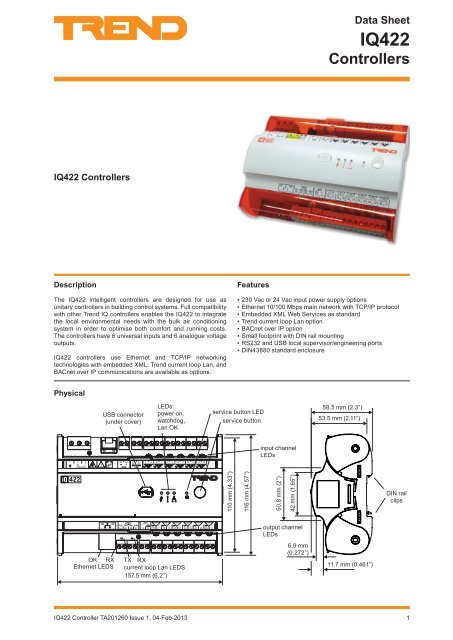
<strong>Data</strong> <strong>Sheet</strong><strong>IQ422</strong>HardwareBox: The controller box is DIN rail mounting. It has sprung DINrail clips enabling it to be clipped on and unclipped from theDIN rail. The /230 version must be installed inside an enclosurerated to at least IP20 or equivalent. The /24VAC version shouldbe installed in an enclosure or outside normal reach (e.g. in aplenum).The units have a plastic housing with rotating clear polycarbonatecovers for the top and bottom terminal rows. The current loopLan LEDs (TX, RX) can be viewed through one cover. TheEthernet LEDs (RX, OK) are fitted into the end of the Ethernetconnector. The input/output LEDs have light pipes so they canbe seen adjacent to the appropriate terminal label.The USB connector in centre of the cover is protected by aretained flexible plastic plug. The cover is pierced with holes toexpose the power, watchdog and service button LEDs, and theservice button is fitted alongside.The unit may be mounted vertically in a panel,or vertically sideon, but not vertically upside down nor flat on its base.Input PowerThe <strong>IQ422</strong> has both 230 Vac and 24 Vac input power options./230: This option requires 230 Vac ±10%, 50/60 Hz. The <strong>IQ422</strong>input power earth (ground) terminal is isolated from the inputpower neutral, and must be separately earthed (grounded)locally; this ground terminal is internally connected to the <strong>IQ422</strong>electronics earth (ground).The 230 V supply must include a dedicated 5 A fuse complyingwith BS1362 and a suitably rated switch in close proximity andbe clearly marked as the disconnecting device for the unit. A5 A circuit breaker with high breaking capacity may be used asan alternative.The 24 V supply must include a suitably rated switch in closeproximity and be clearly marked as the disconnecting devicefor the unit.Fused PrimaryPanel/enclosure ground.<strong>IQ422</strong> 24 Vac powerinput terminals24 VacUL Listed,Class 2, 24 VactransformerThe local earth terminal (1) must be earthed (grounded) at thecontroller.If one side of the transformer secondary is earthed, then thisMUST be connected to the controller’s 0 V terminal (2).Current Loop LanThe current loop Lan is an optional feature (<strong>IQ422</strong>/LAN). Thecurrent loop Lan is enabled as prime network in the IQ LANnetwork module, otherwise Ethernet is the prime network.Address/Baud rate: The address on the Lan is soft-configuredin the Address module to be unique on the Lan. The addressand Lan number are set up in the factory on a rolling basis, soin a batch of <strong>IQ422</strong>’s, each will have a different default address(printed on the unit’s label).ENL5 ABy default the baud rate is auto-detected in the range 1k2, 4k8,9k6, 19k2, 38k4 (where 4k8 = 4.8 kilobaud). Automatic baudrate detection (autobaud) may be disabled, in which case thebaud rate must be soft configured to be the same as the rest ofthe Lan. Autobaud should be disabled if:The Lan consists of all IQ4s, and this <strong>IQ422</strong> is set to bethe baud rate master; it must have its baud rate fixed bysetting it manually.1 2 3N L230VAC/24VAC: This option requires 24 Vac ±10%, 50/60 Hz. The24 Vac uses an half wave rectifier internal power supply unit.Multiple controllers with half wave power supplies may bepowered from a single grounded transformer but the supplypolarity must be maintained across all units supplied from thesame transformer.The <strong>IQ422</strong> has problems detecting the baud rateindicated by the Lan OK green LED flashing for longerthan 30 s.Network terminals: The network terminals facilitate connectionof 2 wire cables.Example 2 wire wiringRRTTEarth (ground)panel/enclosure ground.X<strong>IQ422</strong> Controller TA201260 Issue 1, 04-Feb-20135
<strong>Data</strong> <strong>Sheet</strong><strong>IQ422</strong>BackupOutputs LEDs: (yellow - 6 off) Each output channelhas an LED whose light intensity increases with outputvoltage.A supercap is used to maintain the real time clock (time anddate). In the event of power failure this will support the clock for8 days (typically).Note operation at elevated temperature or high humidity levelswill reduce the lifetime of the supercap. Extended operation inthese conditions may permanently reduce the capacity of thiscomponent and result in a reduction in the number of days thatthe controller can successfully backup the time and date.The data (firmware, strategy, parameters) is stored in flashmemory which is non-volatile in the case of power failure.Changes to the address module are stored immediately.Changes are generally stored around midnight, in additionstructural changes (e.g. module interconnections) are stored15 s after the last change, and critical data changes (e.gstrategy values), are stored on power failure or other similarfault condition .Auxiliary Supply OutputThe auxiliary supply out can be used to supply I/O devices e.g.sensors. It provides 20 Vdc ±10%.On the /230 version, 120 mA is available shared between thetop edge terminals, 70, 71 ( 24V ), and another 120 mA from thebottom edge terminal 72, each edge being independently fused.On the /24VAC version 240 mA is available shared between allthree terminals, 70, 71, 72 ( 24V ) which are jointly fused. Reducemaximum current to 200 mA above 40 °C. The combinedcurrent from the auxiliary supply outputs, Wallbus (not currentlyavailable), RS232, and analogue outputs is 240 mA. Exceedingthis current may cause the auxiliary supply output voltage to fallout of specification.The return is through terminal 73 and other ‘C’ terminals; forexample the AUX supply terminal 72 current can return throughterminal 73 as shown in the diagram below.Example wiringThe tools (e.g. SET Live Adjustment. IQTool) will send thearchive instruction after the parameter changes.Inputs and OutputsThe <strong>IQ422</strong> has 6 universal analogue inputs and 6 analogue (0 to10 V) outputs with 3 off 24 Vdc auxiliary supply output terminals:20 VdcAnalogue Outputs6 channels (OUT7 to OUT12)0 to 10 Vdc at up to 20 mA; reduce to 18 mA maximum above+40 °C (+104 °F). Note for combined supply see the limitation inthe ‘Auxiliary Supply Output’ on page 7.Terminals and Example wiringUniversal Inputs6 channels (IN1 to IN6)Load0 to 10 Vensure correct polarityThe universal input channels can either be voltage input (0 to10 V), thermistor input (0 to 200 kohm), digital input (volt freecontact/open collector), or a current input (0 to 20 mA).The input type is set automatically by strategy configuration(rather than having to also set hardware links) and this willswitch in the required resistors using switches A, B, and C.These switches are set appropriately by connecting the channelin the strategy to a digital input module or a sensor module (thesensor type defines the switch settings).3.3Vpanel/enclosure ground2.2kLoadn+20 VdcConnect the analogue output return to the C terminal (e.g.terminal 17) not to an input common. If screened cable is usedthe screen must be connected to the panel/enclosure groundand unterminated at far end. The above diagram shows wiringfor OUT7.C10k100kInput12046k4A B C0VThe switches are automatically selected as shown in the tablebelow:Input type Switch A Switch B Switch CCurrent ON ON offVoltage off ON ONThermistor off off offDigital off off off<strong>IQ422</strong> Controller TA201260 Issue 1, 04-Feb-20137
<strong>IQ422</strong><strong>Data</strong> <strong>Sheet</strong>Thermistor input (0 to 200 kohm): Can be used for athermistor or a potentiometer. The thermistor bridge resistor is12 kohm with a bridge supply 3.3 V.Example wiringpanel/enclosure groundExample wiringExternally poweredLoop poweredexternal power supplyensure correct polarityPanel/enclosureground.If screened cable is used the screen must be connected to thepanel/enclosure ground and unterminated at far end.Voltage input: Provides a 0 to 10 Vdc input. Note that the inputresistance of the <strong>IQ422</strong> analogue voltage input configuration is9.4 kohm as opposed to 208 kohm in the equivalent IQ3 inputso that the scaling for a potential divider input will be different;the selection is facilitated by SET.Example wiringVensure correct polaritypanel/enclosure ground(20 Vdc)24VAUXIf screened cable is used the screen must be connected to thepanel/enclosure ground and unterminated at far end.A loop powered sensor can be connected to the AuxiliarySupply Output.SensorsTB/TS Series: The TB/TS provides a wall mounting thermistorspace sensor that can be connected to an <strong>IQ422</strong> input. TheTB/TS/K also provides setpoint adjustment as a potentiometerinput. The TB/TS/KO has the TB/TS/K features plus anoccupation override push button. The TB/TS/KOF is similar tothe TB/TS/KO but also has fan speed control. The TB/TS/KOSFis similar to the TB/TS/KOF but also has additional occupationstatus LEDs. The TB/TS/KOS is similar to the TB/TS/KO butalso has occupation status LEDs.DisplaysThe <strong>IQ422</strong> controller can be used with IQView, IQView4,IQView8, SDUxcite, and RD-IQ displays.If screened cable is used the screen must be connected to thepanel/enclosure ground and unterminated at far end.Digital input: Can be used for a volt free contact, or for anopen collector. For digital inputs no sensor type is selected soall three switches (A, B, C) are de-energised as required fordigital input signal conditioning.Example wiringvolt free contactopen collectorensure correctpolarityIQView8: The IQView8 is a touch screen network display. Inaddition to showing all the normal strategy items, it can accessdirectories, timezones, and alarms, and users can be set upwith configurable access rights. Schematic displays providethe ability to view, change and graph data from colour graphicspages. (These pages are created in the 963 supervisor andexported to the IQView8). Alarms can be sent directly to theIQView8. It can be connected to network by Ethernet, <strong>Trend</strong>Current loop Lan, or by RS232. The Ethernet connection caneither be by the IQView8’s own virtual CNC or by an externalvCNC (e.g. the <strong>IQ422</strong>’s). The RS232 connection enables theIQView8 to communicate either only with that <strong>IQ422</strong> (if localsupervisor port address is zero), or with the network (if localsupervisor port address is non-zero). It has standard 4 wideterminals to connect to a <strong>Trend</strong> current loop▪▪▪▪The volt free contact has a nominal wetting current of270 µA. The input is on when the contact is closed.There is no polarity.The open collector or open drain (FET) must be able tosink 270 µA. When the transistor or FET conducts, thedigital input will be on. Polarity must be observed.IQView4: The IQView4 is a touch screen colour display panel.It can access inputs, outputs, alarms, and plots, and allowsknobs, switches, timezones, and time to be adjusted. Users canbe set up with configurable access rights. It connects to the<strong>IQ422</strong> by its RS232 port, and it can only communicate with that<strong>IQ422</strong>.SDU-xcite: The SDU-xcite is a wall mounting 4 line display. Inaddition to showing all the normal strategy items, it can accessdirectory modules and the <strong>IQ422</strong>’s alarm log. It connects to the<strong>IQ422</strong> by its RS232 port, and it can communicate only with that<strong>IQ422</strong>.RD-IQ: The RD-IQ is a wall mounting temperature sensor and3 digit display. It has the following variants:Current input: Supports 0 to 20 mA. May be either looppowered or external powered; the type is selected by connectingthe sensor to different terminals as shown.RD-IQ/K: Room display with local temperature sensorand setpoint controlRD-IQ/KOS: As RD/K plus occupation override andoccupation status display.8 <strong>IQ422</strong> Controller TA201260 Issue 1, 04-Feb-2013
<strong>Data</strong> <strong>Sheet</strong><strong>IQ422</strong>RD-IQ/KOSF: As RD-IQ/KOS plus fan speed control.It connects to the <strong>IQ422</strong> by its RS232 port, and it cancommunicate only with that <strong>IQ422</strong>. By default it accesses thefollowing fixed strategy items (although these can be changed):Local temperature S9Setpoint K1Occupation status K6Fan speed status K7FirmwareThe firmware in the <strong>IQ422</strong> CPU board and baseboard can beupgraded over <strong>Trend</strong> current loop Lan or Ethernet (Ethernetrecommended for speed).StrategyThe <strong>IQ422</strong>’s strategy modules are based on the traditionalIQ paradigm with minor changes to increase capability andefficiency. The strategy file (.IQ4) is created and downloadedusing SET.SET facilitates strategy creation by providing an indexed libraryof pre-configured strategy blocks or custom solutions (entirecontroller strategies); these may be viewed, printed, or editedto suit the user. Once the strategy is complete it can be testedprior to download by using the SET controller simulator mode.The strategy file and the other configuration file (backdrop)can be downloaded or uploaded across Ethernet (FTP), Onlythe strategy file (and not back drop files) can be downloadedover <strong>Trend</strong> current loop Lan (<strong>IQ422</strong>/LAN only - at baud rates9k6 or greater), RS232 local supervisor port, and USB localengineering port. Note that Lan, RS232, and USB port upload/downloads will be slower than for Ethernet.An Ethernet download requires the PC running SET to beconnected to Ethernet, and to communicate with the <strong>IQ422</strong>using the <strong>IQ422</strong>’s IP address (SET will actually obtain the IPaddress from the <strong>IQ422</strong> using the IQ System Lan number anddevice addresses). Downloads using the other interfaces areperformed over the <strong>Trend</strong> network (using CNCs).As explained in the Hardware section, the <strong>IQ422</strong> can berestored to defaults by pressing the Service Button (e.g. torecover from a lost PIN when the user hasn’t recourse to <strong>Trend</strong>Technical Support). This will clear down strategy files. It willrestore the following strategy data to defaults (Lan number,outstation address, IP addressing mode, IP address, subnetmask, UDP port, identifier, Router 1, remote <strong>Trend</strong> devices,vCNC). It clears all user modules (passwords, PINs etc), alarmlogs, and plots. Backdrop files are unchanged and time and dateleft at their current settings. After the reset the <strong>IQ422</strong> should bere-configured from scratch and the strategy downloaded.The <strong>IQ422</strong>’s web server provides pages (HTML) which enablelimited configuration from a web browser; most moduleparameters may be viewed and adjusted, but the strategystructure (module interconnections, adding or deleting amodule) cannot be modified from a web browser.AddressingThe <strong>Trend</strong> device Address is set up in the factory on a rollingbasis in the range 11 to 119. The Lan number is set to 20 bydefault.If the <strong>IQ422</strong> has an Ethernet connection the Ethernet addressingparameters should be set up. Each <strong>IQ422</strong> has a unique MAC(Media Access Control) address allocated to its Ethernet node.IP Tool enables the <strong>IQ422</strong>’s address settings (IP address andother Ethernet parameters, Lan number and device address),and virtual CNCs to be set up.For IQ4s on a <strong>Trend</strong> current loop Lan without an Ethernetconnection, IQTool can be used for addressing. If the currentloop Lan contains other controllers (e.g. IQ3s, IQ2s) then IQToolcan discover these automatically, but the IQ4s should be addedto the grid by entering the serial numbers; IQTool can then readdressthe IQ4s if required.If the current loop Lan consists exclusively of IQ4’s, IQToolcan be used to automatically discover them, and resolve theaddresses. Alternatively they can be discovered manuallyeither by pressing their service buttons, or by using a barcodescanner to scan their barcodes on either of the labels.The Lan number should be set up using the SET Device View.Strategy ModulesIn the <strong>IQ422</strong> the number of each type of module may beadjusted to match the requirements of the application as longas the memory capacity of the controller is not exceeded. The<strong>IQ422</strong> has an absolute limit of 4000 modules of which 600 maybe sequenced.Each type of module has memory requirement in brIQs as listedbelow; SET also limits the number of modules as shown in thecolumn below.Module brIQs SET maximumAddress 24 1 (fixed) §Digital Input 28 1000Alarm 14 (8)DestinationAlarm Group 9 500Alarm Route 9 500Alarm Log‡ 0 1 (fixed) (up to 300 alarms) §Analog Node 16 510Digital Byte 16 1012Digital Input# 28 1000Directory 13 500Display 19 500Driver# 57 500Function# 19 500IC Comms# 19 250Knob 13 1000Logic# 19 500Loop 55 500Network 0 §NTD 30 †††Option 0 §OSS 34 500Page 4 500Plot 12 500 ††Program 0 1 (fixed) §Schedule 21 500Sensor# 76 1000Sensor type 12 99Sequence 106† 1 (fixed) (600 steps) §Switch 10 1000Time 38 1 (fixed)Time Zone* 566 100User 12 500Virtual CNC 9 1 §Notes:# For these modules the actual size (numbers of brIQs) varieswith module type. The largest size is shown here.* The time zone brIQ count allows for an average of 20exceptions.<strong>IQ422</strong> Controller TA201260 Issue 1, 04-Feb-20139
<strong>IQ422</strong><strong>Data</strong> <strong>Sheet</strong>§ These modules are always in the <strong>IQ422</strong> (not optional), butthe number of Network modules (1 - Ethernet, 2 - IQ Lan,3 - BACnet IP, BACnet Application etc), and Option modules(BACnet etc) depends on the <strong>IQ422</strong>’s option build.† The sequence table takes 106 brIQs; the table includes 300steps.†† The maximum number of records for a plot is 1000 (5000 logpoints), but maximum total records varies with the type of plotsused as explained above. The maximum number of plots whichcan occur in 1 s is 100 so there could be 100 off 1 s plots (butno others). This is calculated on the average plots service in 1s, so a 1 minute plot would contribute a 1/60. For example 90off 1s, +360 off 1 min would give 90+6= plots/s on average. Theperiodic and triggered plots must also be counted and it’s up tothe engineer to make his best estimate.†††The number of NTDs in the <strong>IQ422</strong> is only limited by theavailable brIQs‡The alarm log can record up to 300 alarms after which the nextalarm will overwrite the first alarm (FIFO). They can be viewedon the <strong>IQ422</strong> web pages (up to 6 pages of 50 alarms)The available capacity is measured in brIQs. The total availablecapacity in an <strong>IQ422</strong> is 16,000 brIQs with 1000,000 log pointsof plot memory.For synchronised plots each plot record requires 5 log points,so the <strong>IQ422</strong> can have up to 200,000 synchronised plotrecords. For triggered or periodic plots, each record requires10 log points, so the <strong>IQ422</strong> can have up to 100,000 triggered orperiodic plot records.SET imposes the limit of 4000 modules. The <strong>IQ422</strong> limits thenumber of destination modules to 8 as shown in the table. Alarmlog, Network, Option, and Program modules have zero brIQs.In SET, as the modules are created, a tally is kept of the brIQsused and the amount available to be used; an indication of thiscan be viewed. If the limit is exceeded, then SET will prohibit thecreation of further modules.It is possible to create modules which are not numericallysequential so module lists can be non-continuous (e.g. L1, L2,L5, L7...).IC CommunicationsThe IQ4s may communicate with each other and IQ2, IQ3, IQeco,and IQL controllers using inter controller communications (peerto peer communications) using <strong>Trend</strong> Lan/node addressing.The <strong>IQ422</strong>/BAC is also able to communicate with BACnetdevices using IC Comms; the ‘Protocol’ parameter specifieseither <strong>Trend</strong> or BACnet protocol. The remote controller in theBACnet IC Comms module specifies a Non-<strong>Trend</strong> Device(NTD)module which is set up with BACnet device’s BACnet addressinformation. The table specifies the types of IC Comms withwhich the <strong>IQ422</strong> will operate.ICCommsTypeToIQ2Initiated inIQ4 or IQ3 IQeco IQ2ToIQecoToIQ3/4ToBACnetToIQ4ToIQ4<strong>Data</strong> From †Yes §Yes †Yes †Yes †Yes *YesAnalogue<strong>Data</strong> From †Yes ††Yes †#Yes No †Yes *#YesDigitalByte<strong>Data</strong> From †Yes ŦYes †#Yes †Yes †Yes *#YesDigital Bit<strong>Data</strong> To Yes §Yes Yes †Yes §Yes YesAnalogue<strong>Data</strong> To *Yes ††Yes *Yes ††Yes No YesDigitalByteICCommsTypeToIQ2Initiated inIQ4 or IQ3 IQeco IQ2ToIQecoToIQ3/4ToBACnetToIQ4ToIQ4<strong>Data</strong> To Yes ŦYes Yes †Yes ŦYes YesDigital BitGlobal To Yes §Yes Yes †Yes §Yes YesAnalogueGlobal *Yes ††Yes *Yes ††Yes No YesTo DigitalByteGlobal To Yes ŦYes Yes †Yes ŦYes YesDigital BitMinimum Yes §Yes *Yes No No *YesMaximum Yes §Yes *Yes No No *YesSum Yes §Yes *Yes No No *YesAverage Yes §Yes *Yes No No *Yes*Only available on v1.2 or greater firmware.†Only available on v2.0 or greater firmware.§Only if item is a knob or sensorŦOnly if item is a switch or digital input.#Although the IQ3/4 will respond to these requests, the digitalbyte module in the IQ3/IQ4 cannot be set up by the strategy.However, Digital Bit <strong>Data</strong> From IC Comms using switch ordigital input status as the parameter value being transferredworks fine.†† Requires IQeco v2.0 or greater.Note that IC Comms with IQ1v3 controllers are similar tothose with IQ2 controllers except the <strong>IQ422</strong> can only receivemessages (i.e. <strong>Data</strong> To from IQ1), not send them. However, ICComms with IQ1v4.1 or greater controllers can be considered tobe the same as those with IQ2 controllers.The receipt of IC Comms by an analogue node or digital bit/byte is implemented by creating analogue node or digital bytemodules during the strategy creation process on SET.IdentificationThe <strong>IQ422</strong> will identify itself as an IQ4 to w comms.AlarmsThe <strong>IQ422</strong> will generate Network, General, and Item alarms.Network alarms are generated by the <strong>Trend</strong> Network nodes,General alarms are generated when the <strong>IQ422</strong> detects aproblem within its own hardware or program, and Item alarmsare generated by the strategy, and are normally due to a faultyplant condition.Network alarms are sent to supervisors or tools connected tothe RS232 local supervisor port, USB local engineering port, orto the controller’s vCNCNetwork, General, and Item alarms can either be sent in text,coded, or attribute format, and can be sent either to a designated<strong>Trend</strong> Lan address, to an IP address, as an email, r to a BACnetdevice (IQ4/BAC only). They are also stored locally in the AlarmLog. Only sensor, digital input, digital driver readback, and plotalarms can be sent to a BACnet device.For coded alarms the protocol limits the item number to 255maximum. For text alarms the maximum item label length is20 characters (although the 963 can be setup to use labelspreviously learnt).Sending an Email alarm requires the Email Server Address tobe set up in the address module. The Email Server Address canbe set up as an IP address, an internet domain name, or a hostname; the internet domain name or host name require a DNSserver address or a WINS server address respectively to be setup in the network module so that the name can be resolved.10 <strong>IQ422</strong> Controller TA201260 Issue 1, 04-Feb-2013
<strong>Data</strong> <strong>Sheet</strong><strong>IQ422</strong>TimemasterThe <strong>IQ422</strong> can act as a Timemaster but doesn’t have a batterybackedreal time clock to support it in case of power failure.However, the supercap will support the clock for 8 days (typical)in the case of power failure.PlotsThe <strong>IQ422</strong>’s plot modules can plot any connectable moduleoutput (analogue or digital). There are three types of plotmodule: synchronised, triggered, and periodic. Although allthree types are BACnet interoperable, only periodic plots canbe compliant with the BACnet standard. All plot modules cangenerate a buffer ready alarm when the number of recordsequals the notification threshold.LanguageThe user can specify which language the <strong>IQ422</strong> uses for thedisplay of web pages and for transmitted alarms. The languagefiles are embedded in the controller. In the controller the Addressmodule has a language parameter which will be set by defaultto the default language, but can be changed to any one of theother available language files or English (e.g. change to Englishby setting the language parameter to ‘english’ on the addressmodule web page). The <strong>IQ422</strong> can use languages which require8 bit code (i.e. special or accented characters) and can alsooperate with right to left languages (e.g. Chinese, Arabic).Web PagesInformation from an <strong>IQ422</strong> controller can easily be accessedusing a Web browser over any TCP/IP network (e.g. a companyIntranet). All that is required is the IP address or host name ofthe controller, and a valid user name and password (if users areset up in the controller). Once connection to the controller hasbeen made, it is possible to view and adjust occupation times,view the alarm history, and view/adjust/graph individual moduleparameters.Web pages may also be accessed by mobile smart phones andtablets (see Compatibility section below for details of compatibleweb browsers).Module parameters may be monitored and changed using webpages but module creation, deletion, and linking can only bedone using SET.The <strong>IQ422</strong> is provided with a standard set of web pages whichcovers all accessible modules.Graphical display pages (GraphIQs) which are configured using<strong>IQ422</strong>’s display and directory modules, can also be accessed.They can be shown over backdrop files which are separatelydownloaded.For further details of web pages see the IQ4 ConfigurationReference Manual (TA201263), the IQ4 Web User Guide,(TC201256), and the Graphical Display Pages Editor Manual,(TE200629).Field MaintenanceThe <strong>IQ422</strong> Controllers require virtually no routine maintenance.The unit should be cleaned with a cloth moistened with water inorder to avoid buildup of dust or other contaminents. Disconnectpower before carrying out any cleaning.WARNING: Contains no serviceable parts.Opening the unit exposes hazardous voltagesDISPOSALCOSHH (Control of Substances Hazardous to Health -UK Government Regulations 2002) ASSESSMENT FORDISPOSAL OF <strong>IQ422</strong> Controllers.RECYCLING .All plastic and metal parts are recyclable. The printed circuitboard may be sent to any PCB recovery contractor to recoversome of the components for any metals such as gold and silver.WEEE Directive:At the end of their useful life the packaging, andproduct should be disposed of by a suitablerecycling centre.Do not dispose of with normal household waste.Do not burn.CompatibilityBrowsers: This device has been successfully tested withInternet Explorer 8 and with the default browser on the followingdevices:iPhone, v5.1 (9B176), MC603ZA,iPad, v5.1 (9B176), MC979HN,HTC One X, v4.03 (Android),Karbonn tablet, v4.03 (Android), SmartTab2.It should work with all modern browsers, smart phones, andtablets (with JavaScript enabled) available at the date of releaseof this product.Owing to the rapidly changing nature of web devices, newdevices and browsers will become available after the release ofthis product. If you would like to check the compatibility of <strong>IQ422</strong>with your device, please connect to: iq4demo.trendcontrols.com. Log in with username: mobile and password: trendSupervisors and Displays: 963 v3.5 or greater, 916, IQView,IQView4, IQView8, RD-IQ, SDU-xcite.Note that the NDP is not compatible with <strong>IQ422</strong>; it will notrecognise an <strong>IQ422</strong> connected to its network.Utility software: SET v6.8 or greaterIC Comms: IQeco, IQ3, IQ2, IQL, and IQ1 (v3 onwards).Controllers: IQ3/IQ4 directly and IQ1, IQ2, IQL by way of3xtend/EINC L. <strong>IQ422</strong>/LAN communicates with IQ2, IQ1directly. IQeco by way of IQ3/BINC.Strategies: IQ1, IQ2, IQ3 can be imported into SET, convertedinto IQ4 strategies, and then downloaded into an <strong>IQ422</strong>. If thestrategy file accesses I/O channels beyond those available inthe <strong>IQ422</strong> the strategy will be rejected.Ethernet Nodes: 3xtend/EINC L, NXIP, or EINC. NXIP or EINCmust not be used in an automatic IP addressing environment.<strong>IQ422</strong> Controller TA201260 Issue 1, 04-Feb-201311
<strong>IQ422</strong><strong>Data</strong> <strong>Sheet</strong>Compatibility (continued)BACnet Devices: IQ4/BAC only. Being tested as a BACnet Application Specific Controller (B-ASC). Compatibility defined in IQ4Product Implementation Conformance Statement (TP201248). All references to BACnet compatibility in <strong>Trend</strong> documentation arereliant on successful certification (not yet achieved).InstallationThe <strong>IQ422</strong> is installed on a DIN rail by using the DIN rail clip. The /230 version must be installed inside an enclosure rated to atleast IP20 or equivalent. The /24VAC version should be installed in an enclosure or outside normal reach (e.g. in a plenum). Theinstallation procedure involves:Mounting the controller in positionConnecting power, do not power upConnecting Ethernet if requiredConnecting RS232 if required for supervisor/tool/display.Connecting USB if required for toolConnecting IQ system Lan (IQ4/LAN only)Terminating the I/O channels, leave unconnectedPowering upSetting up IP address parameters (if Ethernet used)Setting up Lan number and Device address,Checking networkConfiguring the strategyTesting strategy using controller simulation in SETDownloading strategy and other configuration filesCheck BACnet communications (IQ4/BAC only)Connecting inputs and checking operationConnecting outputs and checking operationA full description of installing the unit is given in the <strong>IQ422</strong> Installation Instructions - Mounting (TG201264) and <strong>IQ422</strong> InstallationInstructions - Configuration (TG201265).12 <strong>IQ422</strong> Controller TA201260 Issue 1, 04-Feb-2013
<strong>Data</strong> <strong>Sheet</strong><strong>IQ422</strong>cONNECTIONSThis section provides an overview of the location of the connectors and the types of connections that can be made. For detailedinformation abut each connection see the appropriate section of this data sheet.RS232 Local Supervisor Port (RJ11)For connection of supervisor, tool or display)RJ11 to 9 way ’D type’ female cableCABLE/EJ101442 for PC connectionIQ(RJ11)PC (9 way Dtype female)Universal Inputs (IN1, to IN6)Voltage input (0 to 10V), current input (0 to 20 mA),thermistor input (0 to 200 kohms, or digital inputRJ11 to RJ11RD/SDU-IQ2COMMSCABLE/nM (n=3, 3m; n=10, 10m)for RD-IQ, SDU-xcite, IQView4 connectionCABLE/EJ105650 for IQView8 connectionIQ(RJ11)Display(RJ11)Input Power Connector24 Vac24 VacN L230VAC!USB Local Engineering Port(Micro B USB)For connection of SETIQ (MicroB USB)Standard USB cablePC230 VacE N LAuxiliary Supply OutputAnalogue Outputs (OUT7 to OUT8)1 2 3N L230VACEthernet PortFor connection of Ethernetnetwork or directly to PC(crossover adaptor not required)20 VdcLoadIQ(RJ45)Ethernetnetwork/PC(RJ45)Current Loop Lan (/LAN only)Cat 5e twisted pairRT<strong>IQ422</strong> Controller TA201260 Issue 1, 04-Feb-201313
<strong>IQ422</strong><strong>Data</strong> <strong>Sheet</strong>order codes<strong>IQ422</strong> Basic Order Code Structure<strong>IQ422</strong>/[LAN]/[BAC]/[Power][LAN] Blank No <strong>Trend</strong> current loop LanLAN <strong>Trend</strong> current loop Lan option fitted[BAC] Blank No BACnet protocolBAC BACnet over IP protocol capability option included[Power] 230 230 Vac input power supply24VAC 24 Vac input power supplyNote that XML web services are standard supply in the <strong>IQ422</strong>.Available Order Codes<strong>IQ422</strong>/12/230<strong>IQ422</strong>/12/BAC/230<strong>IQ422</strong>/12/LAN/230<strong>IQ422</strong>/12/LAN/BAC/230<strong>IQ422</strong>/12/24VAC<strong>IQ422</strong>/12/BAC/24VAC<strong>IQ422</strong>/12/LAN/24VAC<strong>IQ422</strong>/12/LAN/BAC/24VAC:<strong>IQ422</strong> with 230 Vac supply with Ethernet:<strong>IQ422</strong> with 230 Vac supply with Ethernet and BACnet over IP:<strong>IQ422</strong> with 230 Vac supply with <strong>Trend</strong> current loop Lan and Ethernet:<strong>IQ422</strong> with 230 Vac supply with <strong>Trend</strong> current loop Lan, Ethernet, and BACnet over IP:<strong>IQ422</strong> with 24 Vac supply with Ethernet:<strong>IQ422</strong> with 24 Vac supply with Ethernet and BACnet over IP:<strong>IQ422</strong> with 24 Vac supply with <strong>Trend</strong> current loop Lan and Ethernet:<strong>IQ422</strong> with 24 Vac supply with <strong>Trend</strong> current loop Lan, Ethernet, and BACnet over IPAccessoriesCABLE/EJ101442:Adaptor cable to connect PC to <strong>IQ422</strong> RS232 local supervisor portRD/SDU-IQ2COMMSCABLE/3M :3 m, 3 yds 10” cable to connect RD-IQ, SDU-xcite, IQView4 to <strong>IQ422</strong> RS232 localsupervisor port (supplied with IQView4)RD/SDU-IQ2COMMSCABLE/10M :10 m, 11 yds cable to connect RD-IQ, SDU-xcite, IQView4 to <strong>IQ422</strong> local supervisor portCABLE/EJ105650RJ11 plug to RJ11 plug with crossover to connect IQview8 to <strong>IQ422</strong> RS232 local supervisorport connectorTP/1/1/22/HF/200:200 m of screened single twisted pair 0.34 mm 2 (22AWG) (Belden equivalent 8761NH), foruse on current loop Lan (IQ4/LAN version), input/output channel wiring (not USA).TP/2/2/22/HF/200:200 m of screened twin twisted pair 0.34 mm 2 (22AWG) (Belden equivalent 8723NH), foruse on current loop Lan (IQ4/LAN version) (not USA).14 <strong>IQ422</strong> Controller TA201260 Issue 1, 04-Feb-2013
<strong>Data</strong> <strong>Sheet</strong><strong>IQ422</strong>SpecificationsElectricalInput power supply voltage/230 :230 Vac ±10% 50/60 Hz at up to 42 VA/24VAC:24 Vac ±10% 50/60 Hz at up to 38 VAFusing:No replaceable fuses required.Power failure protection :All strategy and data in nonvolatilememory. Supercap maintains real timeclock for up to 8 days (typical).Clock accuracy :10 s per month (typical).Cycle time :Sequence table 1s.Ethernet :Main bus, 10BASE-T, 100BASE-T(IEEE 802.3). Supports TCP/IP, FTP.<strong>IQ422</strong> supports auto MDI/MDI-X whicheliminates need for crossover adaptorDistance :100 m, 109 ydsVirtual CNC address :vCNC address to be configured instrategy.RS232 Local Supervisor PortTransmission :RS232, EIA/TIA/232E, V28 supportsIQ System commsDistance :15 m, 16 ydsBaud rate :9k6.Address:Selectable by software, 116 nodesaddressable (1, 4 to 119 excluding2,3,10) set to be unique on Lan.Supply Output :/230, 21 Vdc ±5% at 60 mA maximum/24VAC, unregulated supply will varywith input supply voltage and controllerloading between 17 to 35 Vdc at 60 mAmaximum.Note for combined supply see thelimitation in the ‘Auxiliary SupplyOutput’ on page 7.USB Local Engineering Port:Micro B connector. USB 2.0. Supports480 Mbits/s (Hi-Speed). Maximum cablelength 5 mCurrent Loop Lan (/LAN only)Transmission :20 mA two wire current loop, optoisolated,polarity independent receiver,balanced transmitterDistance :Dependent on cable type, see tablebelow.CableBelden 9182Belden 9207<strong>Trend</strong> TP/1/1/22/HF/200(Belden 8761)<strong>Trend</strong>TP/2/2/22/HF/200(Belden 8723)Baud Rate1k2 4k8 9k6 19k2 38k41000 m (1090 yds)1000 m(1090 yds)700 m(765yds)500 m(545yds)700 m(765yds)500 m(545yds)350 m(380yds)250 m(270yds)500 m(545yds)350 m(380yds)250 m(270yds)125 m(135yds)No. ofWires2Baud rate :Auto-detected in range 1k2, 4k8, 9k6,19k2, 38k4 - set to be same as othernodes on Lan.Address:The <strong>IQ422</strong> address on Lan is set bysoftware. Set to be unique on network;116 nodes addressable (1 to 119excluding addresses 2,3, and 10224Inputs/OutputsSignal Cable :Universal inputs, and analoguevoltage outputs; TP/1/1/22/HF/200recommended (Belden 8761)Universal inputs :6 universal input channels IN1 to IN6.Can be set by software to voltageinput (0 to 10 V), current input (0 to 20mA), thermistor input (0 to 200 kohm),or digital input (volt free contact/opencollector).Voltage input :12 bit resolution. Minimum 60 dB seriesmode rejection at input power supplyfrequency. 0 to 10 V, input resistance9.4 kohm, accuracy 50 mV equivalentto ±0.5% of span.Current input :12 bit resolution (4096 steps - effective).Minimum 60 dB series mode rejectionat input power supply frequency. 0to 20 mA, input resistance 120 ohm,accuracy 0.5% of span (i.e. 100 μA).Can connect either loop powered orexternal powered sensors. Supplyto loop powered sensors by AuxiliarySupply Output.Thermistor input :(potentiometer, thermistor, fan speedcontrol). 0 to 200 kohm 12 bit resolution.Minimum 60 dB series mode rejectionat input power supply frequency.Thermistor bridge resistor 12.2 kohm,accuracy ±0.5% typical at 25 °C (1kohm to 100 kohm). Bridge supply3.3 V.Digital input :(volt free contact, open collector (ordrain)). Count rate 30 Hz (minimumpulse width of 16.6 ms). 3.3 V supplythrough 12 kohm.Volt free contact input :Wetting current = 270 µAnominal. (ON = closed contact.)Open collector (or drain) input :Must be able to sink270 µA . Must be earthed (grounded) tosame earth (ground) as <strong>IQ422</strong>. Polaritydependent. (ON = transistor/FETAnalogue Outputsconducts.):6 analogue output channels OUT7 toOUT12. 11 bit resolution (2048 steps).0 to 10 Vdc at up to 20 mA, reduce to18 mA maximum above +40 °C (+104°F). Accuracy ±0.5% of span. Note forcombined supply see the limitation inthe ‘Auxiliary Supply Output’ on page 7.Auxiliary Supply Output:20 Vdc ±10%. Return through terminal73 and other ‘C’ terminals./230 120 mA maximum shared betweenterminals 70, 71, plus 120 mA maximumfrom terminal 72/24VAC240 mA maximum shared between allthree terminals, 70, 71, 72. Reducemaximum current to 200 mA above40 °C. Note for combined supply seethe limitation in the ‘Auxiliary SupplyOutput’ on page 7.IndicatorsPower ( ) :Green LEDWatchdog ( ) :Red LEDLan OK ( ) :Green LEDService Button ( ) :Yellow LEDRX:Yellow LEDTX:Yellow LEDOK:Green LEDRX:Yellow LEDIN1 to IN6 :Yellow LEDOUT7 to OUT12 :Yellow LED<strong>IQ422</strong> Controller TA201260 Issue 1, 04-Feb-201315
<strong>IQ422</strong><strong>Data</strong> <strong>Sheet</strong>MechanicalDimensions:116 mm (4.57”) x 157.5 mm (6.2”) x58.5 mm (2.3”).MaterialMain body :PCABS FRTerminal covers :Translucent PC FRWeight :/24VAC:366 gm (0.8 lb)/230 :402 gm (0.88 lb)ConnectorsPower:2 part connectors with rising cageclamp screw terminals for 0.5 to 2.5mm 2 cross section area (20 to 14 AWG)I/Ocable.:2 part connectors with rising cageclamp screw terminals for 0.5 to 2.5mm 2 cross section area (20 to 14 AWG)cable.Current loop Lan :2 part connectors with rising cageclamp screw terminals for 0.5 to 2.5mm 2 cross section area (20 to 14 AWG)cable.Supervisor port :RJ11 (FCC68).Ethernet:RJ45 connector.USB :Micro B connector. USB 2.0.EnvironmentalEMC:EN61326-1:2006Immunity :Table 2 - for equipment intended foruse in industrial locationsEmissions :Class BSafety:EN61010-1:2010CB Certification Scheme :TBAAmbient limitsStorage:-25 °C (-13 °F) to +60 °C (+140 °F)Operating :-25 °C (-13 °F) to +55 °C (+131 °F).Humidity :0 to 90 %RH non-condensingAltitude :


