GX2355S - Standard Horizon
GX2355S - Standard Horizon
GX2355S - Standard Horizon

You also want an ePaper? Increase the reach of your titles
YUMPU automatically turns print PDFs into web optimized ePapers that Google loves.
ON-LINE WARRANTY REGISTRATIONPlease visit www.standardhorizon.com to register the SPECTRUM+Marine VHF. It should be noted that visiting the Web site from time totime may be beneficial to you, as new products are released they willappear on the STANDARD HORIZON Web site.PRODUCT SUPPORT INQUIRIESIf you have any questions or comments regarding the use of theSPECTRUM+, you can visit the STANDARD HORIZON Web site tosend an E-Mail or contact the Product Support team at 562/404-2700M-F 7:00-5:00PST.FCC RADIO LICENSE INFORMATION<strong>Standard</strong> <strong>Horizon</strong> radios comply with the Federal Communication Commission (FCC)requirements that regulate the Maritime Radio Service.STATION LICENSEAn FCC ship station license is no longer required for any vessel traveling in U.S. waterswhich uses a VHF marine radio, RADAR or EPIRB, and which is not required to carry radioequipment. However, any vessel required to carry a marine radio on an international voyage,carrying a HF single side band radiotelephone or marine satellite terminal is required tocarry a license. FCC license forms, including applications for ship (506) and land stationlicenses can be downloaded via the Internet at www.fcc.gov/forms. To obtain a form fromthe FCC, call (888) 225-5322.RADIO CALL SIGNCurrently the FCC does not require recreational boaters to have a Ship Radio StationLicense. The USCG recommends the boats registration number and the state to be used.CANADIAN SHIP STATION LICENSINGYou may need a license when traveling in Canada. If you do need a license contacttheir nearest field office or regional office or write:Industry CanadaRadio Regulatory BranchAttn: DOSP300 Slater StreetOttawa, OntarioCanada, KIA 0C8<strong>GX2355S</strong> Owner’s Manual page 1
FCC NOTICENOTICEUnauthorized changes or modifications to this equipment may voidcompliance with FCC Rules. Any change or modification must beapproved in writing by STANDARD HORIZON.NOTICEThis equipment has been tested and found to comply with the limits fora Class B digital device, pursuant to Part 15 of the FCC Rules. Theselimits are designed to provide reasonable protection against harmfulinterference in a residential installation. This equipment generates,uses and can radiate radio frequency energy and, if not installed andused in accordance with the instructions, may cause harmfulinterference to radio communications. However, there is no guaranteethat interference will not occur in a particular installation. If thisequipment does cause harmful interference to radio or televisionreception, which can be determined by turning the equipment off andon, the user is encouraged to try to correct the interference by one ormore of the following measures:— Reorient or relocate the receiving antenna.— Increase the separation between the equipment and receiver.— Connect the equipment into an outlet on a circuit different fromthat to which the receiver is connected.— Consult the dealer or an experienced radio/TV technician for help.page 2 Owner’s Manual <strong>GX2355S</strong>
1 GENERAL INFORMATION1.1 INTRODUCTIONThe STANDARD HORIZON <strong>GX2355S</strong> is a VHF/FM transceiver designedfor use in the frequency range of 156.025 to 163.275 MHz. The <strong>GX2355S</strong>requires 13.8V for operation and has a switchable RF output power of 1watt or 25 watts.The transceiver is capable of RTCM SC101 DSC (Digital Selective Calling)operation and intercom operation with the use of an optional RAM mic(CMP23 remote-control speaker/microphone with display).The transceiver operates on all currently-allocated marine channels whichare switchable for use with either USA, International, or Canadianregulations. It has an emergency channel 16 which can be immediatelyselected from any channel by pressing the red 16/9 key. NOAA Weatherchannels can also be accessed immediately by pressing the WX key withchannel selection.Other features of the transceiver include: scanning, priority scanning,public address (PA) mode, submersible noise-canceling speaker mic, highand low voltage warning, and GPS repeatability.1.2 FCC/ INDUSTRY CANADA INFORMATIONThe following data pertaining to the transceiver is necessary to fill out thelicense application.Type Acceptance ................................................................... FCC Part 80Output Power .......................................... 1 Watt (low) and 25 Watts (high)Emission..................................................................... 16K0F3E, 16K0G3EFrequency Range................................................ 156.025 to 163.275 MHzFCC Type Number ............................................................... K66GX2350SIndustry Canada Type Approval .......................................... 511822205AV<strong>GX2355S</strong> Owner’s Manual page 3
2 ACCESSORIES2.1 PACKING LISTWhen the package containing the transceiver is first opened, please checkit for the following contents:• <strong>GX2355S</strong> SPECTRUM + Transceiver (White/Black)• CMP351W/CMP351B (White/Black Microphone attached to thetransceiver) and hanger kit• Mounting Bracket and attaching hardware• Spare Fuse (6 A, 250 V )• Owner’s Manual• Quick-Reference Card• Accessory Cable• Power Cord• Dust Cover2.2 OPTIONSCMB16 ...................................................................... Flush-Mount BracketCMP23 ................. Remote-Access Microphone (RAM Mic, Black / White)CAW23 ............................................ 10-foot Extension Cable for RAM MicCVS2500 .......................................................................... Voice Scrambler101S ...................................................................... Mini Extension Speaker201S ................................................................... White Extension Speaker201SZ............................................ White Flush Mount Extension Speaker201SBK .............................................................. Black Extension Speaker201SBKZ ........................................ Black Flush Mount Extension Speaker220SW ...........................................................4.5" Round Hailer / PA Horn240SW ............................................. 5" X 8" Rectangular Hailer / PA Hornpage 4 Owner’s Manual <strong>GX2355S</strong>
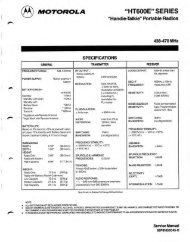
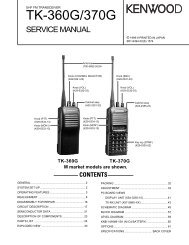
3 CONTROLS AND INDICATORSNOTEThis section defines each control of the transceiver. See Figure 1 forlocation of controls. For detailed operating instructions refer to chapter4 of this manual.3.1 CONTROLS AND CONNECTIONSq POWER SWITCH/VOLUME CONTROLTurns the transceiver on and off as well as adjusts the audio volume. Toturn the transceiver on press and hold this knob until the LCD turns on.To turn it off, press and hold this knob until the LCD turns off. When thepower is turned on, the transceiver is set to the last selected channel.Secondary UseWhen the transceiver is turned on while the SCAN and WX keys are helddown, the internal microprocessor is reset. This clears the memory and alluser-programmed settings, such as scan memory, priority scanassignments, and A/B channel assignments. This condition is known asthe default condition, the same as when shipped from the factory. For alist of these defaults, see the section on Resetting the Transceiver’sMicroprocessor.NOTEResetting the microprocessor will not erase DSC MMSI and DirectoryCall Waiting information.w SQUELCH CONTROL (SQL)Sets the point at which random noise on the channel does not activatethe audio circuits but a received signal does. This point is called thesquelch threshold. Further adjustment of the squelch control willdegrade reception of wanted transmissions.e KEY PAD16/9 KeyImmediately recalls channel 16 from any channel location. Holdingdown this key recalls channel 9. Pressing the 16/9 key again reverts tothe previous selected working channel.Secondary usePlease see secondary use for the WX and MEM key.<strong>GX2355S</strong> Owner’s Manual page 5
PULL OPEN16 9VOL / PWRqw xUICSPECTRUM+ICA/B H/L PA/FOG NAVrPA VOLSCANMEMCALLSETMENUDISTRESSSQLwteiyou!2!016/9!3!1Figure 1. Controls and Connectorspage 6 Owner’s Manual <strong>GX2355S</strong>
WX KeyImmediately recalls the previously selected NOAA weather channelfrom any channel location.Secondary use1. Holding down the 16/9 key while pressing the WX key changes themode from USA to International or Canadian.NOTEIf position is displayed, this icon will be hidden.2. Holding down the WX and SCAN key while turning the power on resetsthe microprocessor and erases scan channels from memory. This clearsthe memory and establishes the factory-set defaults. For a list of thesedefaults, see the section on Resetting the Transceiver’s Microprocessor.SCAN Key1. Starts and stops scanning of programmed channels.2. If held while the UP or DOWN keys on the mic case are pressed orChannel Selector knob on radio is turned, the radio will show thechannels in scan memory. This function will not work if the unit is scanning.NOTEThere is only one priority channel. However, it can be assigned to achannel other than WX and CH70. The priority channel is marked withP-CH on the LCD.MEM KeyMemorizes the selected channel into the transceivers scan memory forscanning. When pressed again, it DELETES the channel from the scanmemory.Secondary useThe MEM key is also used to select a priority channel.1. Select the desired channel.2. Press and hold the MEM key until the display shows P-CH.NOTEIf position is displayed, this icon will be hidden.DISTRESS KeyTo send the distress call see section 6.2, (Sending a Distress Call).PA/FOG keyAvailable to operate the PA function or the FOG HORN function<strong>GX2355S</strong> Owner’s Manual page 7
A/B KeyImmediately recalls two user assigned channels from any channel.CALL/SET KeyThe CALL/SET key functions as the enter key.Secondary usePress the CALL/SET key to access the DSC OPERATION menu. Thefollowing DSC functions can be accessed from the DSC OPERATIONmenu; INDIVIDUAL, GROUP, ALL SHIPS, TELEPHONE, STANDBY,CALL WAIT, POS REQUEST and POS SEND.Press and hold the CALL/SET key to access the SETUP menu. Thefollowing functions can be accessed in the SETUP menu; LAMP ADJUST,CONTRAST, CH NAME, INDIV DIR, TELEPHONE MEMORY ID, POSREPLY, SCRAMBLER, KEY BEEP, INDIV RING, TIME SET, USERMMSI, GROUP MMSI, DSC SCAN.H/L KeyToggles between high and low power. When the H/L key is pressedwhile the transceiver is on channel 13 or 67, the power will temporarilyswitch from LO to HI power until the PTT is released. The H/L key doesnot function on transmit inhibited and low power only channels.NAV / IC Key1. Pressing this key, when connected to the GPS receiver, the LCDdisplays position data, Date, Time, SOG (Speed Over Ground) andCOG (Course Over Ground) from the GPS.2. Press and hold down this key, when the optional RAM Mic isconnected. Intercom operation will operate between radio and RAMMic.r CHANNEL SELECTOR KNOBRotary knob used to select channels and, to choose the item selectionof different functions (DSC operation, PA/FOG operation and etc.). TheCH key on the microphone can also be used to select them.Secondary UseWhile holding down the SCAN Key and turning the Channel Selectorknob, you can confirm memory channels for scanning.t RAM MIC CONNECTORConnects the Remote Access Microphone (RAM MIC). Refer to“section 8.0, (RAM MIC OPERATION).page 8 Owner’s Manual <strong>GX2355S</strong>
y ACCESSORY CONNECTION CABLEConnects the radio to a GPS, external PA horn, and an externalspeaker.u DC INPUT CABLEConnects the radio to a DC power supply of 13.8Vi ANTENNA JACKConnects an antenna to the transceiver. Use a marine VHF antennawith an impedance of 50 ohms.o PTT (Push-To-Talk) SWITCHKeys the transmitter when the transceiver is in radio mode. If thetransceiver is in the intercom operation mode, it activates themicrophone for the intercom.!0CLEAR VOICE NOISE-CANCELING SPEAKER MICTransmits the voice message with reduction of background noise.!1UP and DOWN KEYSThe UP and DOWN on the mic function the same as the ChannelSelector knob on the front panel of the transceiver.!216/9 KeyPressing the 16/9 key Immediately recalls channel 16 from anylocation. Press and hold the 16/9 key to recall channel 9. Pressing the16/9 key again reverts the radio to the previous select channel.!3MICROPHONE SPEAKERThe same audio heard through internal radio speaker as heard throughmicrophone speaker.<strong>GX2355S</strong> Owner’s Manual page 9
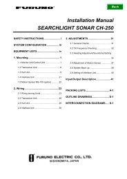
16/9APU L OPEN4 INSTALLATION4.1 LOCATION1. The radio can be mounted at any angle. Choose a mountinglocation that:• is far enough from any compass to avoid any deviation in compassreading due to the speaker magnet• provides accessibility to the front panel controls• allows connection to a power source and an antenna• has nearby space for installation of a microphone hanger• the antenna must be mounted at least 3 feet from radio4.2 ELECTRICAL CONNECTIONSCAUTIONReverse polarity connections will damage the radio!Connect the power cord and antenna to the radio. Antenna and PowerSupply connections are as follows (see Figure 2):AntennaOptional SpeakerWater proofDeck OutletFuseAccessory cableVOL/PWRRedBlack16/9WXHI USAA/B H/L PA/FOG NAVSCAN MEMCALLSPECTRUM+/SETDISTRE SSQLPower SourceFigure 2. General InstallationGPS Navigation Receiver1. Mount the antenna at least 3 feet away from the radio. At the rear ofthe radio, connect the antenna cable. It must have a PL259connector. RG-8/U coaxial cable must be used if the antenna is 25feet or more from the radio. RG58 cable can be used for distancesless than 25 feet.GPS Chart 150page 10 Owner’s Manual <strong>GX2355S</strong>
2. Connect the red power wire to a 13.8 VDC ± 20% power source.Connect the black power wire to a negative ground.3. If an optional remote extension speaker is to be used, refer tosection 4.3 for connections.4. It is advisable to have a Certified Marine Technician check thepower output and the standing wave ratio of the antenna afterinstallation.4.3 ACCESSORY CABLE4.3.1 Cable pin number and signalPin number Signal1 External speaker (+)42 External speaker (–)5 3 3 PA (+)4 NMEA IN (+)6 8 25 PA (–)7 16 NMEA IN (–)7 NMEA OUT (–)8 NMEA OUT (+)NMEA 0183 Version (1.5 to 2.3 ) Input Sentences:GLL – Geographic Position–Longitude/LatitudeRMC – Recommended Minimum Specific GNSS DataNMEA 0183 Version (2.3) Output Sentences:DSC – Digital Selective Calling InformationDSE – Expanded Digital Selective Calling InformationWhen connecting the external speaker or GPS navigation receiver, strip offabout 1 inch (2 cm) of the specified wire’s insulation.NOTENever short wires. This may lead to malfunctions.To <strong>GX2355S</strong>White: External speaker (+)Yellow: External speaker (–)Blue: NMEA IN (+) of GPS navigation receiverGreen: NMEA IN (–) of GPS navigation receiverBrown: NMEA OUT (–) to <strong>Standard</strong> <strong>Horizon</strong> GPS ∗ 1Gray: NMEA OUT (+) to <strong>Standard</strong> <strong>Horizon</strong> GPS ∗ 1Black: PA (–)Red: PA (+)To external speaker, PA speaker and GPS receiver∗1: Connecting these wires to <strong>Standard</strong> <strong>Horizon</strong> GPS to show a DSC PositionRequest, Position Send or Distress Call on the display of the GPS.<strong>GX2355S</strong> Owner’s Manual page 11
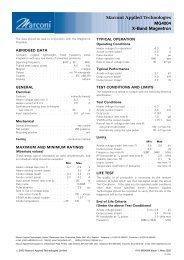
4.4 CMB16 FLUSH MOUNT INSTALLATION1. Make a rectangular template for the flush mount measuring 2-1/8" Hx 5-3/4" W.2. Use the template to mark the location where the rectangular hole isto be cut. Confirm the space behind the dash or panel is deepenough to accommodate the transceiver (at least 6 inches deep).There should be at least 1/2 inch between the transceiver’s heatsinkand any wiring, cables or structures.3. Cut out the rectangular hole and insert the transceiver.4. Fasten the brackets to the sides of the transceiver with the lockwasher nut combination, so that the mounting screw base faces themounting surface (see Figure 3).5. Turn the adjusting screw to adjust the tension so that thetransceiver is tight against the mounting surface.Bracketadjusting screwLock-washer nut combinationFigure 3. CMB16 Flush Mount Installationpage 12 Owner’s Manual <strong>GX2355S</strong>
5 BASIC OPERATION5.1 RECEPTION1. After the transceiver has been installed, ensure that the powersupply and antenna are properly connected.2. Press and hold the VOL/PWR knob until the radio turns on.3. Turn the SQL knob fully counterclockwise. This state is known as“squelch off”.4. Turn up the volume until noise or audio from the speaker is at acomfortable level.5. Turn the SQL knob clockwise until the random noise disappears.This state is known as the “squelch threshold.”6. Press the UP or DOWN key to select the desired channel. Refer tothe channel chart (section 11 CHANNEL ASSIGNMENTS) foravailable channels.7. When a message is received, adjust the volume to the desiredlistening level. The “BUSY” indicator in the LCD is displayedindicating that the channel is being used.5.2 TRANSMISSION1. Perform steps 1 through 6 of RECEPTION.2. Before transmitting, monitor the channel to ensure it is clear. THISIS AN FCC REQUIREMENT!3. Press the PTT (push-to-talk) switch. The TX indicator on the LCD isdisplayed.4. Speak slowly and clearly into the microphone.5. When the transmission is finished, release the PTT switch.NOTEThis is a noise-canceling microphone. The oval slot on the top front ofmicrophone should be positioned within 1 inch (2 cm) from the mouthfor optimum performance.6. Refer to the section 9 OPERATING PRACTICES for standardtransceiver operating procedures.<strong>GX2355S</strong> Owner’s Manual page 13
5.3 TRANSMIT TIME - OUT TIMER (TOT)When the PTT switch on the microphone is held down, transmit time islimited to 5 minutes. This prevents unintentional transmissions. About 10seconds before automatic transmitter shutdown, a warning beep will beheard from the speaker(s). The transceiver will automatically go to receivemode, even if the PTT switch is continually held down. Before transmittingagain, the PTT switch must first be released and then pressed again.5.4 SIMPLEX/DUPLEX CHANNEL USERefer to the channel chart (section 11 CHANNEL ASSIGNMENTS) forinstructions on use of simplex and duplex channels.NOTEAll channels are factory-programmed in accordance with FCC (USA),Industry Canada (Canada), and International regulations. Mode ofoperation cannot be altered from simplex to duplex or vice-versa.5.5 USA, CANADA, AND INTERNATIONAL MODE1. To change the modes, hold the 16/9 key and press the WX key. Themode changes from USA to International to Canadian with eachpress of the WX key.2. USA will be displayed on the LCD for USA mode, INTL will bedisplayed for International mode, and CAN will be displayed forCanadian mode.3. Refer to the channel chart (section 11 CHANNEL ASSIGNMENTS)for allocated channels in each mode.page 14 Owner’s Manual <strong>GX2355S</strong>
5.6 NOAA WEATHER CHANNELS1. To receive a NOAA weather channel, press the WX key from anychannel. The transceiver will go to the last selected weatherchannel.2. Turn the Channel Selector knob on the radio or on the microphoneto select a different NOAA weather channel.3. To exit from the NOAA weather channels, press the WX key. Thetransceiver returns to the channel it was on prior to a weatherchannel.5.7 NOAA WEATHER ALERTIn the event of extreme weather disturbances, such as storms andhurricanes, the NOAA (National Oceanic and Atmospheric Administration)sends a weather alert accompanied by a 1050 Hz tone and subsequentweather report on one of the NOAA weather channels. The transceiver iscapable of receiving this alert if the following is performed:1. Program NOAA weather channels into the transceiver’s memory forscanning. Follow the same procedure as for regular channels underSection 5.8.2. Press the SCAN key once to start memory scanning or hold downthe SCAN key during memory scanning to start priority scanning.3. The programmed NOAA weather channels will be scanned alongwith the regular-programmed channels. However, scanning will notstop on a normal weather broadcast unless a NOAA alert isreceived.4. When an alert is received on a NOAA weather channel, scanningwill stop and the transceiver will emit a loud beep to alert the user ofa NOAA broadcast.5. Press the WX key to stop the alert tone and receive the weatherreport.NOTEIf the WX key is not pressed the alert tone will be emitted for 5 minutesand then the weather report will be received.<strong>GX2355S</strong> Owner’s Manual page 15
5.8 MEMORY SCANNING (M-SCAN)NOTE• During scanning, the dot matrix area of the LCD will show M-SCAN orP-SCAN depending on the scan mode selected.• The channel numbers programmed will cycle on the LCD.• If position is displayed this icon will be hidden.1. Adjust the SQL knob until background noise disappears.2. Select a desired channel to be scanned using the ChannelSelector knob. Press the MEM key, MEM will appear on the LCDwhich indicates the channel has been programmed into thetransceivers memory.3. Repeat step 2 for all the desired channels to be scanned.4. To DELETE a channel from the transceiver’s memory, press theMEM key, MEM will disappear in the LCD.5. To start scanning, press the SCAN key. Scanning will proceed fromthe lowest to the highest programmed channel number and will stopon a channel when a transmission is received.6. The channel number will blink during reception.BUSY HI USAM–SCANVTSA7. To stop scanning, press the SCAN, 16/9, WX, or PTT key.5.9 PRIORITY SCANNING (P-SCAN)1. Any channel can be set as the priority channel, other than weatherchannels and channel 70. To set the priority channel, select thedesired channel. Press and hold down the MEM key until P-CH isshown on the display.MEM HI USAP–SCAN CH16A2. To select priority scanning, hold down theSCAN key until P-SCAN appears on the LCDduring memory scanning. Scanning will proceedbetween the memorized channels and thepriority channel. The priority channel will bescanned after each programmed channel.MEM CH. P-CH. CH. 70 MEM CH. P-CH. CH. 70(When DSC scaningis available)(When DSC scaningis available)page 16 Owner’s Manual <strong>GX2355S</strong>
BUSY HI USAT/W CH16VTSA3. The scanning will be performed while receivingthe MEM CH (memorized channel).4. To stop scanning, press the SCAN, 16/9, WX, or PTT key.NOTETriple watch (T/W) means the radio is watching CH70 for DSC Calls.Dual watch (D/W) means the radio is not watching CH70 for DSC Calls.5.10 CHANNEL A /B INSTANT CALLTwo calling channels (used by an organization or a favorite channel)can be preset. But USA channels 9 and 16, and WX channels shouldnot be assigned as A or B channels because they are readily availablewith the 16/9 and WX keys. If the A/B key is pressed and no channel Aor B has been assigned, the alert signal will be present.5.10.1 Storing new channel A/B1. Press and hold down the A/B key and rotate the Channel Selectorknob to select the desired channel.2. Release the A/B key to store a desired channel as channel A/B.3. Repeat steps to program second channel A/B.5.10.2 Changing the stored channel A/B1. Press the A/B key for memorized channel to appear.2. Press and hold down the A/B key and rotate the Channel Selectorknob to select the desired channel.3. Release the A/B key to store a desired channel as channel A/B.NOTEThe stored channels will delete in microprocessor resetting mode only.5.10.3 Operating the channel A/BPressing the A/B key more than once toggles between channel A,channel B and the channel that was received on.5.11.PA/FOG OPERATIONPA HAIL mode:PA HAIL mode allows the transceiver to be used as a power hailer when anoptional 4 ohm hailer speaker is installed. The Hail mode has a listen-backfeature which provides two way communication through the hailer speaker.<strong>GX2355S</strong> Owner’s Manual page 17
FOG HORN mode:Automatic signaling is transmitted through the PA speaker.5.11.1 Operating the PA HAIL modePUBLICADDRESSVOLUME1. Press the PA/FOG key.Toggle between the PA HAIL and FOG HORNmode by pressing the PA/FOG key.2. Press the PTT switch to speak through the hail speaker.Rotate the Channel Selector knob to control the AF output level.The AF output level can be set from 0 to 20 watts.3. To exit the PA HAIL mode, press the 16/9, WX or CALL SET key.5.11.2 Operating the FOG HORN modeOperator can select from FOG 1, FOG 2, FOG 3, FOG 4, HORN, SIREN,AGROUND, or ANCHOR.FOG 1: POWER BOAT UNDERWAYFOG 2: POWER BOAT STOPPEDFOG 3: SAIL BOAT, FISH VESSEL, TOW VESSELFOG 4: VESSEL UNDER TOW>FOG1FOG2FOG3FOG4AA1. Press the PA/FOG key on PA HAIL mode.Toggle between the PA HAIL and FOG HORNmodes by pressing the PA/FOG key.FOG2FOG3FOG4>SIRENA2. Turn the Channel Selector knob to select thefunction.3. Press the CALL/SET key to operate the FOG HORN mode.Horn – When PTT is pressed, emits HORN SOUND from the PA speaker.Siren – When PTT is pressed, emits SIREN SOUND from the PA speaker.SIRENVOLUMEA4. On the SIREN and FOG HORN modes, pressthe PTT switch to activate the tone through thePA speaker.Turn the Channel Selector knob to control theAF output level. The AF output level can be setfrom 0 to 20 watts.5. To exit the FOG HORN mode, press the 16/9, WX or CALL SETkey.page 18 Owner’s Manual <strong>GX2355S</strong>
5.12 NAVIGATION INDICATIONThe transceiver has the ability to display the time, SOG and COG date, aswell as the vessel’s position (LAT/LON), if connected to a GPS receiver.JUN15 8:45P15 KT 160T35 . 55. 000'N138 . 28. 000'WHI USAINVALIDNO POSTIONDATAAA1. Press the NAV key to display positioninformation.If the GPS receiver receives no signal, thedisplay will be as shown in the illustration on theleft.2. To hide the position information, press the NAVkey.NOTE• The TIME OFFSET should be set to local time in the DSC/RADIOsetup mode when the radio is connected to the GPS navigationreceiver. To adjust TIME OFFSET to your local time, refer to section7.11 TIME OFFSET.5.13 VOICE SCRAMBLERIf privacy of communications is desired, a CVS2500 voice scrambler (VS)can be installed in the transceiver. Contact your Dealer to have a CVS2500installed. Refer to the section 7.8 of DSC/RADIO SET UP mode to programthe voice scrambler.5.13.1 Operation with voice scrambler1. Turn on the transceiver.HI USAVS 3COMMERCIALHI USACOMMERCIALHI USAVS OFFCOMMERCIALAAA2. Select a channel that was programmed forscrambler mode. (Example: the voice scramblercode is set 3.)If a channel is not set for the voice scrambler,the display will be as shown in the illustration onthe left.If a voice scrambler is canceled temporarily inthe SETUP menu, the display will be as shownin the illustration on the left.3. Monitor the channel before transmitting.4. Transmit the voice message. The signal sentwill be scrambled.<strong>GX2355S</strong> Owner’s Manual page 19
5.14 RESETTING THE TRANSCEIVER’S MICROPROCESSORResetting the microprocessor restores the initial, factory suppliedconditions in the transceiver. These are called the default conditions.To reset the microprocessor, first turn the transceiver off. Then whilepressing the WX and SCAN keys, turn the transceiver on. The defaultconditions are:• No channels in the SCAN memory.• Channel 16 will be selected when the transceiver is turned on.• WX channel 01 will be recalled when the WX key is pressed.• Key beep will be on.• No channels will be stored in the A/B memory.NOTEResetting the microprocessor will not erase DSC MMSI and DirectoryCall Waiting information.page 20 Owner’s Manual <strong>GX2355S</strong>
6 DIGITAL SELECTIVE CALLING6.1 GENERAL6.1.1 Digital Selective Calling (DSC)Digital Selective Calling is a semi-automated method of establishing aradio call, it has been designated by the International MaritimeOrganization (IMO) as an international standard for establishing VHF, MFand HF radio calls. It had also been designated part of the Global MaritimeDistress and Safety System (GMDSS). It is planed that DSC will eventuallyreplace aural watches on distress frequencies and will be used toannounce routine and urgent maritime safety information broadcasts.This new service will allow mariners to instantly send a distress call withGPS position (when connected to the transceiver) to the USA Coast Guardand other vessels within range of the transmission. DSC will also allowmariners to initiate or receive distress, urgency, safety and routine calls toor from another vessels equipped with a DSC transceiver.6.1.2 Maritime Mobile Service Identity (MMSI)What is an MMSI?An MMSI is a nine digit number used on Marine Transceiver capable ofusing Digital Selective Calling (DSC). This number is used like a telephonenumber to selectively call other vessels. Refer to section 7.7 (USER MMSIINPUT).How can I obtain a MMSI assignment?Contact your dealer or <strong>Standard</strong> <strong>Horizon</strong> for details.WARNINGThis radio is designed to generate a digital maritime distress andsafety call to facilitate search and rescue. To be effective as a safetydevice, this equipment must be used only within communication rangeof a shore-based VHF marine channel 70 distress and safety watchsystem. The range of signal may vary but under normal conditionsshould be approximately 20 nautical miles.<strong>GX2355S</strong> Owner’s Manual page 21
6.2 SENDING A DISTRESS CALLThe distress call automatically includes the vessel’s DSC MMSI and Lat/Lon position. Refer to section 7.12, USER MMSI INPUT. The vessel’sposition can be sent only if the transceiver is properly connected to anoperating GPS receiver.6.2.1 Sending a Distress Call Automatically>DISTRESSNATURE OFEXIT1.Lift the red spring loaded DISTRESS coverand press the DISTRESS key. The distressmenu will appear on the LCD.NOTEIf GPS is connected skip steps 2 and 3 and go directly to step 4.(When No GPS is connectedor INVALID is displayed, LCDshows below figure.)DISTRESS>SENDMANUALEXITAA2. Press the DISTRESS or CALL/SET key untilthe distress sending menu appear.When a GPS is connected and INVALID is notdisplayed, LCD will show step 4.3. Turn the Channel Selector knob to selectSEND.When you select MANUAL, refer to 6.2.2Sending a Distress Call Manually.PRESS ANDHOLD 3 SECONDFOR TRANSMITTX HI USADISTRESSWAITINGA4. Press and hold the DISTRESS or CALL/SETkey for 3 seconds or more. Holding time willappear on the LCD.5. When the distress signal is sent, the dot-matrixarea of the LCD will be as shown in theillustration on the left.After the message has been sent, the DistressAlarm will sound.6. The transceiver “shadow-watches” for atransmission between CH16 and CH70 until anacknowledgment signal is received. “DISTRESS”and “WAITING” will appear on the LCD.7. If no acknowledgment is received, the distress call is repeated in 4minute intervals until an acknowledgment is received.page 22 Owner’s Manual <strong>GX2355S</strong>
(When DISTRESS signal hasbeen sent and it will be sentagain, LCD shows below figure.)DISTRESSNATURE OF>CANCELEXITDISTRESSID987654321RECEIVED ACKAA8. To cancel a Distress Call, press the 16/9 key,turn the Channel Selector knob to selectCANCEL. Then, press the CALL/SET key orturn off the radio.9. When a distress acknowledgment is received, adistress alarm sounds and channel 16 isautomatically selected.LCD shows ID and the answering type.RECEIVED ACK: acknowledgment signal is received.RECEIVED RLY: relay signal is received fromother vessel or coast station.10. To cancel the alarm, press any key.NOTEWhen a GPS receiver with NMEA output is connected, the vessel’sposition is automatically transmitted with the distress call.6.2.2 Sending a Distress Call and Manually Inputting a Position1. Perform steps 1 through 2 of 6.2.1 Sending aDistress Call Automatically.DISTRESSSEND>MANUALEXITDISTRESSUTC0 . 0:0000' N0 . 00' WAA2. Turn the Channel Selector knob to selectMANUAL and press the CALL/SET key.3. Turn the Channel Selector knob to select thedesired numeral and press the CALL/SET key.UTC (Universal Time Coordinates also known asGMT) area is entered for a time. The time can beentered through 0:00 - 23:59. “– . – –' N” area isentered the north latitude. The north latitude canbe entered through 0 . 00 - 90 . 00. “– . – –' W” areais entered the west longitude. The westlongitude can be entered through 0 . 00' - 180 . 00.4. Press and hold the DISTRESS key for 3 seconds or more. Holdingtime will appear on the LCD.5. Perform steps 5 through 10 of 6.2.1 Sending a Distress CallAutomatically.<strong>GX2355S</strong> Owner’s Manual page 23
6.3 SENDING A DISTRESS CALL WITH NATUREOF DISTRESSThe NATURE OF on type of distress call can be selected and transmitted.The distress call automatically includes the vessels DSC MMSI and Lat/Lon position. The vessels position will be sent only if the transceiver isproperly connected to an operating GPS receiver.>DISTRESSNATURE OFCANCELEXITDISTRESS>NATURE OFCANCELEXIT>FIREFLOODINGCOLLISIONGROUNDINGAAA1. Lift the red spring loaded DISTRESS cover andpress the red DISTRESS key. The distress callmenu will appear.2. Turn the Channel Selector knob or press theUP or DOWN key on the microphone to selectthe nature of distress ( NATURE OF).3. Press the CALL/SET key.The dot-matrix area of LCD will be as shown inthe illustration on the left.4. Turn the Channel Selector knob or press the UP or DOWN key onmicrophone to select the NATURE OF DISTRESS. To send aDISTRESS CALL with NATURE OF DISTRESS, press and holdCALL/SET key until the distress signal is sent.FIREWAITING5. After a message has been sent, the transceiver“DSC SCAN” between CH16 and CH70 until anacknowledgment is received. (Example: Fire issent.)6. If no acknowledgment is received, the distress call is repeated in 4minute intervals until an acknowledgment is received.To cancel this, turn power OFF then ON again.7. When a distress acknowledgment is received, emergency alarmsounds and channel 16 is automatically selected.8. To cancel the alarm, press any key.page 24 Owner’s Manual <strong>GX2355S</strong>
6.4 SENDING AN INDIVIDUAL CALLThis feature allows the user to contact another user vessel DSC and toautomatically switch the receiving DSC radio to a desired working channel.This feature is similar to calling a vessel on CH16 and requesting to go toanother channel. To send an individual call, see section 7.5 INDIVIDUALDIRECTORY SETUP. The individual call function allows you to transmit aDSC signal to a specific party only, prompting communication on a voicechannel.CCGHI USAA1. Select the traffic channel for voice communication.>INDIVIDUALGROUPALL SHIPSTELEPHONE>TOMMIKEBOBDICKAA2. Press the CALL/SET key.The DSC CALLING menu will appear.3. Turn the Channel Selector knob to selectINDIVIDUAL.(To cancel, select EXIT with the ChannelSelector knob or press the 16/9 key.)4. Press the CALL/SET key.The transceiver will beep, and the individualdirectory will appear.TOMMIKE>BOBDICKINDIVIDUALBOBWAITINGNO REPLYBOB>SENDEXITCCGHI USAAAA5. Turn the Channel Selector knob to select theindividual you want to contact.6. Press the CALL/SET key to transmit theindividual DSC signal.7. After INDIVIDUAL CALL is transmitted, thetransceiver will wait 8 seconds for theacknowledgment. If the reply signal is notreceived, the transceiver will transmit again.8. After the second INDIVIDUAL CALL istransmitted, if the reply signal is not received,the dot matrix area of the LCD will display“>SEND” to prompt the user to send the callagain or exit the mode.9. When an individual call acknowledgment “ableto comply” is received, the established channelis automatically selected and an alarm sounds.<strong>GX2355S</strong> Owner’s Manual page 25
UNATTENDEDBOB>SENDEXITA10. When an individual call acknowledgment with“unable to comply” is received, the establishedchannel is automatically selected.11. To cancel, select EXIT using the Channel Selector knob and pressthe CALL/SET key.This procedure can be also canceled as follows;Press the CALL/SET key or 16/9 key.6.5 SENDING A GROUP CALLThis feature allows the user to contact a group of specific vessels usingDSC and to automatically switch to a desired channel. This feature allowsyou to transmit a DSC signal with group MMSI that has been set accordingto section 7.13 Group MMSI INPUT.CCGHI USAA1. Select the desired channel to use Group Call forvoice communications.>INDIVIDUALGROUPALL SHIPSTELEPHONEINDIVIDUAL>GROUPALL SHIPSTELEPHONEGROUP>SENDEXITTX HI USAWAITINGCCGHI USAAAAAA2. Press the CALL/SET key. The DSC CALLINGmenu will appear.3. Turn the Channel Selector knob to select GROUP.To cancel, select EXIT with the ChannelSelector knob or press 16/9 key.4. Press the CALL/SET key.5. Turn the Channel Selector knob to select SEND.To cancel, select EXIT with the ChannelSelector knob or press 16/9 key.6. Press the CALL/SET key.When the Group Call signal is sent, the dotmatrixarea of the LCD will be as shown in theillustration on the left.7. After the GROUP CALL is transmitted, all theradios in the group will switch to the designatedchannel.page 26 Owner’s Manual <strong>GX2355S</strong>
6.6 SENDING AN ALL SHIPS CALLThe All Ships Call function allows contact to be established with othervessel stations without having their ID in the individual calling directory.Also, priority for the call can be designated as Urgency, Safety or Routine.URGENCY Call: This type of call is used when a vessel may not truly be indistress, but have a potential problem that may lead to a distress situation.SAFETY Call: Used to transmit boating safety information to other vessels.This message usually contains information about an overdue boat, debris inthe water. Loss of a navigation aid or an important meteorological message.CCGHI USA>INDIVIDUALGROUPALL SHIPSTELEPHONEAA1. Select the traffic channel (for voicecommunication).2. Press the CALL/SET key. The DSC CALLINGmenu will appear.INDIVIDUALGROUP>ALL SHIPSTELEPHONE>URGENCYSAFETYROUTINEEXIT>URGENCYSAFETYROUTINEEXITTX HI USAWAITINGHI USADISTRESSAAAA3. Turn the Channel Selector knob to select ALLSHIPS.4. Press the CALL/SET key.To cancel this, turn the Channel Selector knobto select EXIT.5. Turn the Channel Selector knob to select thenature of call (URGENCY, SAFETY or ROUTINE).6. Press the CALL/SET key to transmit theselected type of ALL SHIPS DSC call. WhenROUTINE is selected, the signal is transmittedthen the transceiver will wait on the channelselected in step 1.7. After the ALL SHIPS CALL is transmitted, thetransceiver will wait on CH16 except ROUTINE.<strong>GX2355S</strong> Owner’s Manual page 27
6.7 MariTEL DSC TELEPHONE CALLDSC telephone function allows the user to transmit and receive DSCtelephone calls automatically from ship to a shore based telephone (MariTel)coast station, or from a shore based telephone to your vessel. TheSpectrum+ has a telephone directory similar to a cellular phone. Phonenumbers have to be preprogrammed into to the memory of the radio beforethis function will operate properly. See section 7.6 Telephone ID setup.6.7.1 Sending a Ship to Shore Call>INDIVIDUALGROUPALL SHIPSTELEPHONEINDIVIDUALGROUPALL SHIPS>TELEPHONETOM>MIKEBOBDICKAAA1. Press the CALL/SET key.The DSC CALLING menu will appear.2. Turn the Channel Selector knob to selectTELEPHONE.3. Press the CALL/SET key.4. Turn the Channel Selector knob to selecttelephone name you want to contact.TX HI USATELEPHONEMIKETX HI USAMIKEWAITINGHI USATELEPHONEMIKE>END CALLTX HI USATELEPHONEMIKETELEPHONECALL FINISHEDELPSD TIME00 : 03 : 25TELEPHONECALL FINISHEDELPSD TIME-- : -- : --5. Press the CALL/SET key.When the Telephone call signal is sent, the dotmatrixarea of the LCD will be as shown in theillustration on the left.6. When the transceiver receives the telephonecall starting signal, the channel is switched totelephone call channel and the alarm will sound.If you receive no acknowledgment signal, referto 6.7.3 Resend Telephone Call Signal. If youreceive Busy signal, refer to 6.7.4 ResendTelephone Call When Receive Busy Signal.7. To end Telephone Call, press the CALL/SETkey.8. When the transceiver has received the telephonecall ending signal, the transceiver is switched tothe previous channel and the elapsed time will beshown as the illustration on the left.If no elapsed time data is received, “– – : – – : – –”will be shown.page 28 Owner’s Manual <strong>GX2355S</strong>
6.7.2 Receiving a Shore to Ship CallAfter a DSC Telephone call from a shore station has been received the radiowill automatically be switched to the MariTel Marine operator channel.HI USATELEPHONE>END CALLTELEPHONECALL FINISHEDELPSD TIME00 : 03 : 25TELEPHONECALL FINISHEDELPSD TIME-- : -- : --1. When the transceiver receives the telephone callstarting signal from the shore, the alarm will sound.2. To take the incoming call, press the PTT andstart talking to the person.3. To end the call, press the CALL/SET key.4. When the transceiver has received thetelephone call ending signal, the transceiver isswitched to the previous channel and theelapsed time will be shown as the illustration onthe left. If no elapsed time data is received "- - : -- :- - " will be shown.6.7.3 Resend Telephone Call SignalWhen you send starting or ending telephone call signal to the coast stationand you receive no acknowledgment signal from coast station during 8seconds or more, Resending menu will appear. You can resend thetelephone call with this menu.NO REPLYMIKE>SENDEXITA1. You receive no acknowledgment signal fromcoast station, the dot-matrix area of the LCD willbe as shown in the illustration on the left.2. Turn the Channel Selector knob to select SEND.To exit the Telephone Call mode, turn the Channel Selector knobto select EXIT and press the CALL/SET key.6.7.4 Resend Telephone Call When Receive Busy SignalWhen you send starting telephone call signal to the coast station and youreceive Busy signal from coast station, a menu will appear. You canresend the telephone call with this menu.UNATTENDEDMIKE>SENDEXITA1. You receive busy signal from coast station, thedot-matrix area of the LCD will be as shown inthe illustration on the left.2. Turn the Channel Selector knob to select SEND.To exit the telephone call, turn the Channel Selector knob to selectEXIT and press the CALL/SET key.<strong>GX2355S</strong> Owner’s Manual page 29
6.8 DSC STANDBYThe DSC Standby function allows the transceiver to reply to DSC calls withthe UNATTENDED message and logs the calls in the call waiting directory(This feature is similar to an answering machine). When set to the DSCStandby mode, voice traffic may still be monitored on the selected channel.>INDIVIDUALGROUPALL SHIPSTELEPHONEA1. Press the CALL/SET key.The DSC CALLING menu will appear.GROUPALL SHIPSTELEPHONE>STANDBYHI USADSC STANDBYUNATTENDEDAA2. Turn the Channel Selector knob to select theSTANDBY mode.3. Press the CALL/SET key.4. When an individual DSC call is received, the radio will respond withthe UNATTENDED message if an operator cannot answer the call.The DSC call will be logged into the radio’s call waiting directory.5. To cancel this, press the 16/9 key.NOTEThis function is available as following;DSC SCAN is turned on, or the current channel is set CH70 if DSCSCAN is turned off.6.9 CALL WAITING DIRECTORYThe DSC Call Waiting directory logs 10 received distress calls, and logs 20individual calls that are received and not answered within 5 minutes or whilethe radio is set on the DSC Standby function. Calls will be logged while busywith other communications as long as the transmitter is not keyed at the timeof the call. If the call is answered within 5 minutes the call will not be logged.When a call is logged, a message will appear on the LCD.NOTEWhen a DISTRESS CALL is received, this call will be logged on thedistress call waiting directory.page 30 Owner’s Manual <strong>GX2355S</strong>
6.9.1 Operation of Distress Call Waiting>INDIVIDUALGROUPALL SHIPSTELEPHONEA1. Press the CALL/SET key.The DSC CALLING menu will appear.ALL SHIPSTELEPHONESTANDBY>CALL WAITA2. Turn the Channel Selector knob to select CALLWAIT.CALL WAIT>DISTRESSINDIVIDUALEXITA3. Press the CALL/SET key.CALL WAIT>DISTRESSINDIVIDUALEXITA4. Turn the Channel Selector knob to selectDISTRESS.JUN15 8:45PID98765432135 . 55.000'N138 . 28.000'WA5. Press the CALL/SET key to display the log datawhich was received last.6. Turn the Channel Selector knob to select another logged call7. To exit from Distress Call Waiting, press the CALL/SET key andselect EXIT.6.9.2 Operation of Individual Call Waiting>INDIVIDUALGROUPALL SHIPSTELEPHONEALL SHIPSTELEPHONESTANDBY>CALL WAITCALL WAIT>DISTRESSINDIVIDUALEXITCALL WAITDISTRESS>INDIVIDUALEXITAAAA1. Press the CALL/SET key.The DSC CALLING menu will appear.2. Turn the Channel Selector knob to select CALLWAIT.3. Press the CALL/SET key.4. Turn the Channel Selector knob to selectINDIVIDUAL.5. Press the CALL/SET key to enter the individuallog.<strong>GX2355S</strong> Owner’s Manual page 31
NAME1NAME2NAME3NAME4A6. Turn the Channel Selector knob to select thename.JUN15 8:45PID987654321>SENDEXITA7. Press the CALL/SET key to display the loggedcall.8. Press the CALL/SET key to resend the INDIVIDUAL CALL.9. To exit from Individual Call Waiting, select EXIT and press theCALL/SET key.10. Turn the Channel Selector knob to select another logged call or toselect EXIT.11. Press the CALL/SET key to access next logged call or EXIT.6.10 POSITION REQUESTThe position request mode may be used to show the position of anothervessel that has a DSC radio with this feature. The other vessel must havean operating GPS receiver connected to its DSC transceiver and must nothave its transceiver set to deny position requests. (Refer the section 7.5 toenter information into the individual directory)>INDIVIDUALGROUPALL SHIPSTELEPHONEA1. Select a traffic channel, then press the CALL/SET key. Then the DSC CALLING menu willappear in the display.TELEPHONESTANDBYCALL WAIT>POS REQUEST>TOMMIKEBOBDICKTOMMIKE>BOBDICKAAA2. Turn the Channel Selector knob or press theUP/DOWN keys on the microphone to select thePOS REQUEST.3. Press CALL/SET key to show the Positionrequest directory. This directory uses theINDIVIDUAL Directory information.4. Turn the Channel Selector knob or press the UP/DOWN keys on the microphone to select a name.TX HI USABOB5. Press the CALL/SET key to transmit theposition request DSC call.page 32 Owner’s Manual <strong>GX2355S</strong>
6. After a DSC position request is transmitted, the transceiver remainson channel 70 until position data is received.POS REQUESTBOB35 . 55.000'N138 . 28.000'WNO REPLYBOB>SENDEXITPOS REQUESTBOBNO POSITIONDATAAAA7. The transceiver received position data from avessel.8. If the transceiver does not receive a reply, theLCD will display “>SEND” to prompt the user tosend the call again or exit the mode.9. If the transceiver received no position data, theLCD will show “NO POSITION DATA”.10. When the transceiver receives the requested position, thetransceiver outputs a NMEA DSC sentence which may be used by a<strong>Standard</strong> <strong>Horizon</strong> GPS chart plotter to show the vessels position.6.11 POSITION SENDThe position send mode may be used to send your position to another radiowith this feature. Your vessel must have an operating GPS receiverconnected to its SPECTRUM+ to send the position and must not have itstransceiver set to deny position send.JUN15 7:00P15KT 160T35 .138 . 88.000'N20.000'W>INDIVIDUALGROUPALL SHIPSTELEPHONESTANDBYCALL WAITPOS REQUEST>POS SEND>TOMMIKEBOBDICKAAAAWhen other vessel receives your position, thetransceiver outputs a NMEA DSC sentencewhich may be used by a <strong>Standard</strong> <strong>Horizon</strong> GPSchart plotter to show your position.1. Select a traffic channel, then press the CALL/SET key. Then the DSC CALLING menu willappear in the display.2. Turn the Channel Selector knob or press theUP/DOWN keys on the microphone to select thePOS SEND.3. Press the CALL/SET key to select the Positionsend directory. This directory uses theINDIVIDUAL Directory information.<strong>GX2355S</strong> Owner’s Manual page 33
TOMMIKE>BOBDICKTX HI USABOBA4. Turn the Channel Selector knob to select aname.5. Press the CALL/SET key to transmit yourposition DSC call.POS SENDMIKE>SENDEXITA6. After your position DSC is transmitted, theresend menu will appear.When you send your position DSC again, selectSEND and press the CALL/SET key.When you exit the mode, select EXIT and pressthe CALL/SET key.7. The transceiver returns to radio mode.6.12 RECEIVING DSC CALLSSeveral types of DSC transmissions can be received. The required actiondepends on the particular DSC type as outlined in the following examples.NOTEIf the radio is receiving on a working channel or transmitting on aworking channel, DSC calls will not be received.6.12.1 Receiving a distress callDISTRESSID36691111135 . 55.000'N138 . 28.000'WDISTRESSID366911111NO POSITIONDATA1. A distress call is received. An emergency alarmsounds.Then channel 16 is automatically selected.2. Press any key to stop the alarm.3. If the received distress data does not include theposition data, the LCD will show the display onthe left.NOTEYou must continue monitoring channel 16 as a coast station mayrequire assistance in any rescue attempt.page 34 Owner’s Manual <strong>GX2355S</strong>
6.12.2 Receiving a distress relay callDISTRESSID36691111135 . 55.000'N138 . 28.000'W1. A distress relay call is received. An emergencyalarm sounds.Then channel 16 is automatically selected.2. Press any key to stop the alarm.NOTEYou must continue monitoring channel 16 as a coast station mayrequire assistance in any rescue attempt.6.12.3 Receiving an all ships callALL SHIPSID366911111JUN15 7:00P2. Press any key to stop the alarm.1. An all ships call is received. An emergencyalarm sounds.Then channel 16 is automatically selected.3. Monitor channel 16 or traffic channel until the URGENCYcommunication is completed.6.12.4 Receiving a geographical area callGEOGRAPHICALID366911111JUN15 7:00P2. Press any key to stop the alarm.1. A geographical call is received. An emergencyalarm sounds (different from DISTRESS). Thenthe requested channel from the other ship isautomatically selected.3. Monitor the traffic channel for an announcement from the calling ship.NOTEThis feature is only available when a GPS receiver is connected.<strong>GX2355S</strong> Owner’s Manual page 35
6.12.5 Receiving an individual callWhen receiving an individual call, an acknowledgment must be sent backto the calling station.INDIVIDUALBOBJUN15 4:00P1. An individual call is received. An individual callalarm sounds. Then the radio automaticallyswitches to the requested channel.2. Press any key to stop the alarm.3. Press the PTT on the mic and talk to the calling ship.6.12.6. Receiving a position requestWhen a position request call is received from another vessel, a callingalarm will sound and POS REQUEST will show in the LCD. Operationand transceiver function differs depending on the SET UP POSREPLAY mode setting.Automatically reply:POS REQUESTJIMJUN15 7:00PA1. When a position request call is received, acalling alarm sounds 4 times. Then requestedposition coordinates are transmittedautomatically.2. To exit from position request display, press any key.Manually reply:POS REQUESTJIM>REPLYEXITA1. When a position request call is received, theLCD will be as shown in the illustration on theleft.POS REQUESTJIM>REPLYEXITA2. A calling alarm sounds 4 times. Then select typeof reply function REPLY or EXIT by using theChannel Selector knob.3. When REPLY is selected, press the CALL/SET key. And therequested position coordinates will be transmitted.4. To exit from position request display, press any key.page 36 Owner’s Manual <strong>GX2355S</strong>
7. DSC / RADIO SETUP MODE7.1 SETUP>LAMP ADJUSTCONTRASTCH NAMEINDIV DIRA1. Press and hold down the CALL/SET key untilthe SETUP menu appears.2. To select the items, turn the Channel Selectorknob.NOTEThe Optional RAM MIC CMP23 cannot change theSETUP menu. The SETUP menu is displayed in the LCDof the CMP23 as shown in the illustration on the right.7.2 LAMP ADJUSTING>LAMP ADJUSTCONTRASTCH NAMEINDIV DIR>HILOOFFHILO>OFF1. Select LAMP ADJUST in the SETUP menu withthe Channel Selector knob.2. Press the CALL/SET key.The lamp adjusting menu will appear.3. Turn the Channel Selector knob to select thedesired level.When OFF is selected, the lamp is extinguished.When HI is selected, the lamp is brightest.4. Press the CALL/SET key to store the selected level.The LCD will return to the SETUP menu.7.3 LCD CONTRASTLANP ADJUST>CONTRASTCH NAMEINDIV DIRCONTRAST1AAAAA1. Select CONTRAST in the SETUP menu with theChannel Selector knob.2. Press the CALL/SET key.The contrast setting menu will appear. Thecontrast level can be set from 1 to 7.<strong>GX2355S</strong> Owner’s Manual page 37
CONTRAST5A3. Turn the Channel Selector knob to select thedesired level. (Example: 5 is selected)The contrast is stronger as the selected level increases.4. Press the CALL/SET key to store the selected level.The LCD will return to the SETUP menu.7.4 CH NAMING1. To select USA, INT or CANADA, press and hold the 16/9 key andpress WX key.LAMP ADJUSTCONTRAST>CH NAMEINDIV DIRCH NAME USAPORT OPRCH NAME USAPORT OPRCH NAME USAVERTEXA2. Select CH NAME in the SETUP menu (pressand hold the CALL/SET key) with the ChannelSelector knob.3. Press the CALL/SET key.4. Turn the Channel Selector knob to select thechannel to be named and press the CALL/SETkey.5. Turn the Channel Selector knob scroll throughthe alphabet and 0 - 9.6. Press the CALL/SET key to enter the desiredletter and move the cursor one space to theright. Repeat procedure until the name iscomplete. The name can consist of up to twelvecharacters, if you do not use all twelve characterpress the CALL/SET key to move to the nextspace. If you clear the previous letter, press theH/L key.7. To enter the name, press the CALL/SET key for 1 second or more.CH NAME USA>NEXTEXIT8. If you want to enter the name of anotherchannel, select NEXT and press the CALL/SETkey. Repeat steps 2 through 6.To return the Setup menu, select the EXIT andpress the CALL/SET key.page 38 Owner’s Manual <strong>GX2355S</strong>
7.5 INDIVIDUAL DIRECTORY SETUP (DSC)LAMP ADJUSTCONTRASTCH NAME>INDIV DIRA1. Press and hold the CALL/SET key until theSETUP menu is displayed.2. Select INDIV DIR by using the ChannelSelector knob.NAMEMMSI––––––––NAMEMMSI––––––––NAME–MMSI––––––––3. Press the CALL/SET key to enter the individualdirectory.4. Turn the Channel Selector knob to display thenext address number.(Example: The address number 01 - 04 havebeen stored in the illustration on the left.)The address number can be set from 01 to 30.5. Press the CALL/SET key to store the addressnumber.6. Turn the Channel Selector knob scroll throughthe alphabet and 0 - 9.NAMEBMMSI––––––––NAMEB OMMSI––––––––7. Press the CALL/SET key to enter the desiredletter and move the cursor one space to theright. Repeat procedure until the name iscomplete. The name can consist of up to elevencharacters, if you do not use all elevencharacters press the CALL/SET key to move tothe next space. This method can also be usedto enter a blank space in the name. To clear theprevious letter, press the H/L key.8. After the eleventh letter or space has been entered, press theCALL/SET key to advance to the MMSI (Maritime Mobile ServiceIdentity Number) number entry.9. Turn the Channel Selector knob to scroll through numbers, 0-9. Toenter the desired number and move one space to the right press theCALL/SET key. Repeat procedure until all nine space of MMSInumber are entered.<strong>GX2355S</strong> Owner’s Manual page 39
BOBMMSI>NEXTEXIT10. After entering the MMSI number press and holdthe CALL/SET key until the screen prompts youto select NEXT or EXIT.11. To enter another individual address select NEXT with the ChannelSelector knob and press the CALL/SET key. Repeat steps 4 through 10.12. To exit the individual directory setup, select EXIT with the ChannelSelector knob and press the CALL/SET key.NOTESelecting NEXT or EXIT will automatically save the name and MMSInumber into memory.7.6 DSC TELEPHONE DIRECTORY ID INPUTCONTRASTCH NAMEINDIV DIR>TELEPHONEA1. Press and hold the CALL/SET key until theSETUP menu is displayed.2. Select TELEPHONE with the Channel Selectorknob and press the CALL/SET key.NAMETELEPHONE#NAME-TELEPHONE#NAMEVERTEX2TELEPHONE#3. Select the desired memory address with theChannel Selector knob and press the CALL/SET key.4. To enter the letter of the name, turn the ChannelSelector knob, scroll through the alphabet and 0- 9 and press the CALL/SET key. Repeatprocedure until the name is complete. The namecan consist of up to eleven characters.5. A cursor will be moved to the telephone number sectionwhen the name is entered up to eleven characters.NAMEVERTEX2TELEPHONE#-NAMEVERTEX2TELEPHONE#←0312345678906. To enter the telephone number, turn the ChannelSelector knob scroll through the 0 - 9 and pressthe CALL/SET key. Repeat procedure until thetelephone number is complete. The telephonenumber can consist of up to 16 digits.The display will show up to 12 digits, when youenter 13 digits or more, the arrow symbol willappear. Press and hold the CALL/SET key tostore the telephone number.page 40 Owner’s Manual <strong>GX2355S</strong>
7. Press and hold the CALL/SET key until CoastMMSI is displayed.TELEPHONE#031234567890COAST MMSI-8. To enter the Coast MMSI, turn the ChannelSelector knob scroll through the 0 - 9 and pressthe CALL/SET key. Repeat procedure until theCoast MMSI is complete. The Coast MMSI canconsist of up to nine digits.9. To store Coast MMSI, press the CALL/SET keyfor 1 second or more.VERTEX2031234567890>NEXTEXIT10. To enter another Telephone Memory ID, selectNEXT and press the CALL/SET key. Repeatsteps 3 through 8. Up to 30 Telephone IDnumbers can be entered.To return the Setup menu, select EXIT andpress the CALL/SET key.NOTERefer to the section 9.3 MAKING TELEPHONE CALLS.7.7 POSITION REQUEST REPLY TYPE1. Press and hold the CALL/SET key until the SETUP menu is displayed.CH NAMEINDIV DIRTELEPHONE>POS REPLY>AUTOMANUALAA2. Select POS REPLY in the SETUP menu withthe Channel Selector knob.3. Press the CALL/SET key.The position request reply type menu willappear.4. Press the Channel Selector knob to select AUTO or MANUAL.In AUTO mode, after a DSC POS Request is received the radio willautomatically transmit your vessels position. In MANUAL mode, thedisplay of the SPECTRUM+ will show who is requesting the position.To send your position, you will have to press the CALL/SET key.5. Press the CALL/SET key to store a selected reply type.The LCD display will return to the SETUP menu.<strong>GX2355S</strong> Owner’s Manual page 41
7.8 VOICE SCRAMBLER1. Press and hold the CALL/SET key until the SETUP menu isdisplayed.INDIV DIRTELEPHONEPOS REPLY>SCRAMBLERA2. Select SCRAMBLER in the SETUP menu withthe Channel Selector knob.>CODECHANNELONOFFA3. Press the CALL/SET key.The scrambler setup menu will appear.4. Select CODE in the SCRAMBLER SETUP menu and press theCALL/SET key.CODE5. Turn the Channel Selector knob to change the0scrambler code.AThe scrambler code can be set from 0 to 3.6. Press the CALL/SET key to store the selected code.The LCD will return the SCRAMBLER SETUP menu.CODE>CHANNELONOFFUSACHANNELAA7. Select CHANNEL in the SCRAMBLER SET UPmenu and press the CALL/SET key.8. Turn the Channel Selector knob to change thescrambled channel.MEM USACHANNELA9. Press the CALL/SET key to store the selected channel.Repeat steps 8 and 9 to set other channels.10. Press and hold down the CALL/SET key to exitfrom the channel select menu.The LCD will return to the SCRAMBLERSETUP menu.CODE>CHANNELONOFFA11. Select ON to use the scrambler operation andpress the CALL/SET key.The LCD will return to the SETUP menu.NOTEThis menu will not appear unless a CVS2500 is installed.page 42 Owner’s Manual <strong>GX2355S</strong>
7.9 KEY BEEP (ON OR OFF)1. Press and hold the CALL/SET key until the SETUP menu isdisplayed.TELEPHONEPOS REPLYSCRAMBLER>KEY BEEP>ONOFFAA2. Select KEY BEEP in the SETUP menu with theChannel Selector knob.3. Press the CALL/SET key.The KEY BEEP setting menu will appear.4. Turn the Channel Selector knob to select ON or OFF.5. Press the CALL/SET key to set the key beep condition.The LCD will return to the SETUP menu.NOTEEmergency alarm and beeps for DSC operation cannot be turned OFF.7.10 INDIVIDUAL RING1. Press and hold the CALL/SET key until the SETUP menu isdisplayed.POS REPLYSCRAMBLERKEY BEEP>INDIV RINGA2. Select INDIV RING in the SETUP menu with theChannel Selector knob.>DEFAULT5 RINGS10 RINGS15 RINGS A3. Press the CALL/SET key.The INDIVIDUAL RING setting menu willappear.4. Turn the Channel Selector knob to select the ringing time for anINDIVIDUAL CALL. DEFAULT setting rings for 3 minutescontinuously.5. Press the CALL/SET key to store the INDIV RING.The LCD will return to the SETUP menu.<strong>GX2355S</strong> Owner’s Manual page 43
7.11 TIME OFFSETSets the time difference between local time and UTC. Time is displayedwhen position (LAT/LON) is displayed by pressing the NAV key.1. Press and hold the CALL/SET key until the SETUP menu isdisplayed.SCRAMBLERKEY BEEPINDIV RING>TIME SETA2. Select TIME SET in the SETUP menu with theChannel Selector knob.TIME SET0 : 00TIME SET– 8 : 00AA3. Press the CALL/SET key.The time offset menu appears.4. Turn the Channel Selector knob to select timeoffset from UTC.See Figure 4 to find your offset time from UTC.If 0:00 is assigned, the time is the same as UTC(Universal Time Coordinated or GMTGreenwich Mean Time)5. Press the CALL/SET key to store the time offset.The LCD will return to the SETUP menu.+2+6+3+5+7+7+9+30+30+30-12 -11 -10 -9-8-7-6-5-4-3-2-10 +1 +2 +3 +4 +5 +6 +7 +8 +9 +10 +11 +12UTC/GMTFigure 4. Offset time tablepage 44 Owner’s Manual <strong>GX2355S</strong>
7.12 USER MMSI INPUT1. Press and hold the CALL/SET key until the SETUP menu isdisplayed.KEY BEEPINDIV RINGTIME SET>USER MMSIUSER MMSI––––––––USER MMSI0 –––––––AAA2. Select the USER MMSI in the SETUP menuwith the Channel Selector knob.3. Press the CALL/SET key.The USER MMSI menu will appear, and the firstspace will blink.4. Turn the Channel Selector knob to set thenumber (0 to 9 ).USER MMSI0 –––––––USER MMSI012345678AA5. Press the CALL/SET key to store the setnumber.The blinking number is stored, and the nextspace will blink. To delete previous letter, pressthe H/L key.6. Repeat steps 3 and 4 to set your MMSI.7. When the last number of your MMSI is in place, press the CALL/SET key to store your MMSI.NOTEUser MMSI can be input only twice. If the user tries toinput MMSI more than twice, the radio will show thedisplay on the right. If the user needs to change theMMSI more than twice, the transceiver will have to besent to Factory Service. Refer to the section 10.2FACTORY SERVICE.ERROR TOOMANY ENTRIESPRESSCALL/SET KEYA<strong>GX2355S</strong> Owner’s Manual page 45
7.13 GROUP MMSI INPUT1. Press and hold the CALL/SET key until the SETUP menu isdisplayed.INDIV RINGTIME SETUSER MMSI>GROUP MMSIA2. Select the GROUP MMSI in the SETUP menuwith the Channel Selector knob.GROUP MMSI––––––––GROUP MMSI0 –––––––GROUP MMSI0 –––––––GROUP MMSI012345678AAAA3. Press the CALL/SET key.The GROUP MMSI menu will appear, and thefirst space will blink.4. Turn the Channel Selector knob to set thenumber (0 to 9 ).5. Press the CALL/SET key to store the setnumber.The blinking number is stored, and the nextspace will blink.6. Repeat steps 3 and 4 to set your GROUP MMSI.7. When the last number of your MMSI is in place, press and holddown the CALL/SET key to store your MMSI.page 46 Owner’s Manual <strong>GX2355S</strong>
7.14 DSC SCANNINGThe radios software has been updated to improve DSC Channel 70SCANNING:1. When a DSC call is received the radio will only show Channel 70 onthe display if the call was directed to the radios MMSI or if it is aDistress or All ships DSC call.2. Selection to turn ON or OFF the DSC SCAN function.When the radio is shipped from the factory it is programmed so CH70 (theDSC channel) is scanned at all times. A selection has been added to theSETUP MENU in the radio to disable the DSC SCAN. However, turning offDSC SCAN will disable the radio from receiving DSC calls i.e.: IndividualCall, All Ships Call, Distress Call and Position Requests. If you want to useany of the functions the selection should be left ON.TO CHANGE DSC SCAN METHOD:1. Press and hold the CALL/SET key to enter into the SETUP mode.USER MMSIGROUP MMSI>DSC SCANEXIT>ONOFFAA2. Select DSC SCAN using the Channel Selectorknob.3. Press the CALL/SET key. The DSC SCANsetting menu will appear.4. Turn the Channel Selector knob to select ON or OFF.5. To store the selection, press the CALL/SET key. The LCD willreturn to the SETUP menu.<strong>GX2355S</strong> Owner’s Manual page 47
8 RAM MIC OPERATIONIf the optional RAM Mic (CMP23) is connected to the remote microphoneconnector on the transceiver’s rear panel, then the transceiver can use theremote control operation except for a few functions. The RAM Mic has amaximum range of 50 feet (15 m) with the use of two 10-foot extensioncables (CAW23). The intercom operation can be used between the RAMMic and the transceiver.8.1 RAM MIC CONTROLS AND CONNECTIONSPOWER SWITCH (PWR)Turns the transceiver on and off.Press and hold down the PWR key until the LCD turns on. To turn thetransceiver off with the RAM Mic, press and hold the PWR key until theLCD turns off.SQUELCH KEY (SQL)Activates the squelch adjusting mode.Press this key to activate the squelch adjusting mode. Press the orkey to adjust the squelch.Sets the point at which random noise on the channel does not activate theaudio circuits but a received signal does. This point is called the “squelchthreshold”. Further adjustment of the squelch control by pressing thekey will degrade the reception of wanted transmissions.When the SQL key is pressed and held down for 1 second or more, thesquelch is turned off.VOLUME KEY (VOL)Activates the volume adjusting mode.Press this key to activate the volume adjusting mode. Press the orkey to adjust the volume.PTT (Push-To-Talk) SWITCHActivates transmission.16/9 KEYImmediately recalls channel 16 from any channel location. Press and hold the16/9 key to recall channel 9. Recalls the previous channel when the 16/9 keyis pressed again. When holding down the 16/9 key while pressing the WX key,the mode toggles between USA, International and Canadian.page 48 Owner’s Manual <strong>GX2355S</strong>
MIC16/9 WX SCAN A/BLAMPICH/LCALLSQL VOL PWRFigure 5. CMP23 RAM MicA/B KeyImmediately recalls two user assigned channels from any channel.IC KeyActivates the intercom mode between the RAM Mic and the transceiver.Refer to section 8.3, INTERCOM OPERATION.WX KeyImmediately recalls a weather channel from any channel location. Recallsthe previous channel when the WX key is pressed again.Secondary useWhen holding down the 16/9 key while pressing the WX key, the modetoggles between USA, International and Canadian.SCAN Key1. Starts and stops scanning of programmed channels.2. If held while the UP or DOWN key is pressed, the radio will show thechannels in scan memory. This function will not work if the unit is scanning.Secondary usePress the MEM key to add the selected channel to the transceiver’s scanmemory, MEM will appear on the LCD to indicate that the channel hasbeen entered into scan memory. To delete the channel from scan memory,press the MEM key until the MEM disappears from the LCD.NOTEIf the transceiver is in the M-SCAN mode, then the RAM Mic is in SCmode. If the transceiver is in P-SCAN mode, then the RAM Mic is inPS mode.<strong>GX2355S</strong> Owner’s Manual page 49
DOWN KEY ( )Selects the desired channel and adjusts the volume and squelch levels.Each press decreases the channel number, volume level and squelchlevel. When held down, the channels or levels decrease continuously.UP KEY ( )Selects the desired channel and adjusts the volume and squelch levels.Each press increases the channel number, volume level, and squelchlevel. When held down, the channels or levels increase continuously.Secondary useWhen holding down the 16/9 key while pressing the UP key, changes thebrightness (3 levels) of the LCD back light.H/L KEYToggles between high and low power. When the H/L key is pressed whilethe transceiver is on Canadian channel 13, USA channel 13 or 67, thepower will temporarily switch from LO to HI power until the PTT switch ispressed. The H/L key does not function on transmit-inhibited and lowpower-only channels.8.2 INDICATORSTX BUSY USA I NTLCANS DMEMHA LSQL VOLChannel DisplayDisplays the operating channel in both transmission and reception mode.A IndicatorA simplex channel in USA or Canadian mode whose counterpart in theInternational mode is a duplex channel.TX/ BUSY Indicator“TX” is displayed in transmitting mode. “BUSY” is displayed in receivingmode.USA/ INTL/ CAN IndicatorThe mode of operation. “USA” indicates USA mode. “INTL” indicatesInternational mode and “CAN” indicates Canadian mode.WX IndicatorA weather channel.page 50 Owner’s Manual <strong>GX2355S</strong>
16/9PU L OPEN<strong>Horizon</strong>MICRAM mic16/9 WX SCAN A/BLAMPICH/LCALLSUBMERSIBLEMEM IndicatorThe channel is in the transceiver’s scan memory.H/L Indicator“H” is high power. “L” is low power. Blank is a reception only channel.SQL/VOL Indicator“SQL” is squelch adjusting mode. “VOL” is volume adjusting mode.8.3 INTERCOM OPERATION16/9WXA/B H/L PA/FOG NAVSCAN MEMCALLSPECTRUM+/SETDISTRE SEXTERNALSPEAKERNOTE:If the RAM Mic is connected tothe transceiver, the externalspeaker volume is controlledby the RAM Mic. If the RAMMic is not connected to thetransceiver, the externalspeaker volume is controlledby the radio.RAM MicFigure 6. Intercom operationVOL/PWRSQL8.3.1 Communication1. Press the IC key while in radio mode, the mode is then changed toINTERCOM mode. If the IC key is pressed again the mode willrevert to radio mode.2. “IC” is displayed on both the transceiver and the RAM Mic when theintercom operation is activated.3. Press the PTT switch. The “TX” indicator is displayed.NOTEA warning beep is emitted when the RAM Mic PTT switch is pressedwhile the transceiver microphone’s PTT switch is pressed.4. Speak slowly and clearly into the microphone, hold the microphoneabout 1/2 inch away from your mouth.5. When finished, release the PTT switch.8.3.2 Calling1. Hold down the IC key in the intercom operation for 1 second ormore. A calling beep is emitted twice from the transceiver speaker.<strong>GX2355S</strong> Owner’s Manual page 51
9 OPERATING PRACTICES9.1 EMERGENCY (CHANNEL 16 USE)Channel 16 is known as the Hail and Distress Channel. An emergencymay be defined as a threat to life or property. In such instances, be surethe transceiver is on and set to CHANNEL 16. Then use the followingprocedure:1. Press the microphone push-to-talk switch and say “Mayday, Mayday, Mayday.This is , , ” (your vessel's name).2. Then repeat once: “Mayday, ,” (your vessel’s name).3. Now report your position in latitude/longitude, or by giving a true or magneticbearing (state which) to a well-known landmark such as a navigation aid orgeographic feature such as an island or harbor entry.4. Explain the nature of your distress (sinking, collision, aground, fire, heartattack, life-threatening injury, etc.).5. State the kind of assistance your desire (pumps, medical aid, etc.).6. Report the number of persons aboard and condition of any injured.7. Estimate the present seaworthiness and condition of your vessel.8. Give your vessel's description: length, design (power or sail), color and otherdistinguishing marks. The total transmission should not exceed 1 minute.9. End the message by saying “OVER”. Release the microphone button andlisten.10. If there is no answer, repeat the above procedure. If there is still no response,try another channel.9.2 CALLING ANOTHER VESSEL (CHANNEL 16 OR 9)Channel 16 may be used for initial contact (hailing) with another vessel.However, its most important use is for emergency messages. This channelmust be monitored at all times except when actually using another channel.It is monitored by the U.S. and Canadian Coast Guards and by othervessels. Use of channel 16 for hailing must be limited to initial contactonly. Calling should not exceed 30 seconds, but may be repeated 3 timesat 2-minute intervals. In areas of heavy radio traffic, congestion on channel16 resulting from its use as a hailing channel can be reduced significantly inU.S. waters by using channel 9 as the initial contact (hailing) channel fornon-emergency communications. Here, also, calling time should notexceed 30 seconds but may be repeated 3 times at 2-minute intervals.page 52 Owner’s Manual <strong>GX2355S</strong>
Prior to making contact with another vessel, refer to the channel charts inthis manual, and select an appropriate channel for communications afterinitial contact. For example, Channels 68 and 69 of the U.S. VHF Chartsare some of the channels available to non-commercial (recreational)boaters. Monitor your desired channel in advance to make sure you will notbe interrupting other traffic, and then go back to either channel 16 or 9 foryour initial contact.When the hailing channel (16 or 9) is clear, state the name of the othervessel you wish to call and then “this is” followed by the name of yourvessel and your Station License (Call Sign). When the other vessel returnsyour call, immediately request another channel by saying “go to”, thenumber of the other channel, and "over." Then switch to the new channel.When the new channel is not busy, call the other vessel.After a transmission, say “over”, and release the microphone's push-totalk(PTT) switch. When all communication with the other vessel iscompleted, end the last transmission by stating your Call Sign and the word“out”. Note that it is not necessary to state your Call Sign with eachtransmission, only at the beginning and end of the contact.Remember to return to Channel 16 when not using another channel. Someradios automatically monitor Channel 16 even when set to other channelsor when scanning; see your Owner's Manual.9.3 MAKING TELEPHONE CALLSTo make a radiotelephone call, use a channel designated for this purpose,The fastest way to learn which channels are used for radiotelephone trafficis to ask at a local marina. Channels available for such traffic aredesignated Public Correspondence channels on the channel charts inthis manual. Some examples for USA use are Channels 24, 25, 26, 27, 28,84, 85, 86, and 87. Call the marine operator and identify yourself by yourvessel's name, The marine operator will then ask you how you will pay forthe call (telephone credit card, collect, etc.) and then link your radiotransmission to the telephone lines.The marine telephone company managing the VHF channel you are usingmay charge a link-up fee in addition to the cost of the call.<strong>GX2355S</strong> Owner’s Manual page 53
9.4 OPERATING ON CHANNELS 13 AND 67Channel 13 is used at docks and bridges and by vessels maneuvering inport. Messages on this channel must concern navigation only, such asmeeting and passing in restricted waters.Channel 67 is used for navigational traffic between vessels.By regulation, power is normally limited to 1 Watt on these channels. Yourradio is programmed to automatically reduce power to this limit on thesechannels. However, in certain situations it may be necessary to temporarilyuse a higher power. See page 8 (H/L key) for means to temporarily overridethe low-power limit on these two channels.9.5 PROHIBITED COMMUNICATIONSThe FCC prohibits the following communications:n False distress or emergency messages:n Messages to "any boat" except in emergencies and radio tests;n Messages to or from a vessel on land;n Transmission while on land;n Obscene, indecent, or profane language (potential fine of $10,000).9.6 NOAA WEATHER ALERT TESTINGIn the event of a major storm or other appreciable weather conditionrequiring vessels at sea or other bodies of water to be notified, the NOAA(National Oceanographic and Atmospheric Administration) broadcasts a1050 Hz tone that some marine VHF radios can detect. (Refer to Section5.7 “NOAA WEATHER ALERT” on how to use this feature.) This tone,when detected, will produce a loud beep from the radio speaker to signalthat a weather alert is being broadcast.In order to test this system, the NOAA broadcasts the 1050 Hz tone everyWednesday, sometime between 11 AM and 1 PM. Any marine VHF radiothat can detect the weather alert tone, may use this test to verify that thisfeature is functioning properly,page 54 Owner’s Manual <strong>GX2355S</strong>
9.7 DIGITAL SELECTIVE CALLING (DSC)Digital Selective Calling is a semi-automated method of establishing a radio call, ithas been designated by the International Maritime Organization (IMO) as aninternational standard for establishing VHF, MF and HF radio calls. It has also beendesignated part of the Global Maritime Distress and Safety System (GMDSS) and itis planned that DSC will eventually replace aural watches on distress frequenciesand will be used to announce routine and urgent maritime safety informationbroadcasts.This new service will allow mariners to instantly send a distress call with GPS position(when connected to the transceiver) to the US Coast Guard and other vessels withinrange of the transmission. DSC will also allow mariners to initiate or receive distress,urgency, safety and routine calls to or from another vessel equipped with a DSCtransceiver.9.7.1 USCG DSC WatchThe USCG has plans to upgrade its VHF National Distress System (expected by2005), so at the time of printing only larger vessels that are required to carry VHFDSC radios will be able to hear your distress transmission9.8 MARITIME MOBILE SERVICE IDENTITY (MMSI)9.8.1 What is a MMSI?A MMSI is a nine digit number used on Marine Transceivers capable of using DigitalSelective Calling (DSC). This number is used like a telephone number to selectivelycall other vessels.9.9 USING DIGITAL SELECTIVE CALLING FEATURES9.9.1 Distress CallTransmits a DSC Distress message to all radios equipped to receive a DSC Distresscall. Some <strong>Standard</strong> <strong>Horizon</strong> radios may be connected to a GPS to also transmit theLatitude, Longitude of the vessel.9.9.2 Individual CallThis feature allows the user to contact another vessel capable of using DSC andautomatically switch the radio to a desired working channel. This feature is similar tocalling a desired vessel on CH16 and requesting them to go to another channel.<strong>GX2355S</strong> Owner’s Manual page 55
9.9.3 Group CallThis feature allows the user to contact a group or vessels capable of using DSC toautomatically switch the radios to a desired working channel for voice communication.9.9.4 Urgency CallThis call should be used when a vessel may not be truly in distress, but have apotential problem that might lead to a distress situation.9.9.5 Safety CallUsed to transmit boating safety information to other vessels. This message usuallycontains information about an overdue boat, a derelict afloat, loss of a navigation aidor an important meteorological message.9.9.6 Position requestUsed to poll another vessel position via DSC and show it on the LCD of the radio.9.9.7 Telephone CallUsed to automatically place a telephone call through a shore based telephonecompany. (In the U.S. market contact maritel at 1866 - marinet for subscription details)9.10 ADDITIONAL DIGITAL SELECTIVE CALLINGINFORMATIONFor additional information the USCG has an excellent site that should be visited atwww.navcen.uscg.mil/marcoms/gmdss/dsc.html9.11 ABOUT VHF RADIOThe radio frequencies used in the VHF marine band lie between 156 and 158 MHzwith some shore stations available between 161 and 163 MHz. The marine VHFband provides communications over distances that are essentially “line of sight” (VHFsignals do not travel well through objects such as buildings, hills or trees). Actualtransmission range depends much more on antenna type, gain and height than onthe power output of the transmitter. On a fixed mount 25W radio transmission expecteddistances can be greater than 15 miles, for a portable 5W radio transmission theexpected distance can be greater than 5 miles in “line of sight”.page 56 Owner’s Manual <strong>GX2355S</strong>
9.12 SELECTING AN ANTENNAMarine antennas are made to radiate signals equally in all horizontal directions, butnot straight up. The objective of a marine antenna is to enhance the signal toward thehorizon. The degree to which this is accomplished is called the antenna’s gain. It ismeasured in decibels (dB) and is one of the major factors in choosing an antenna. Interms of effective radiated power (ERP), antennas are rated on the basis of howmuch gain they have over a theoretical antenna with zero gain. A 3 foot, 3dB gainantenna represents twice as much gain over the imaginary antenna. The length ofthe antenna you choose, however, must also be related to the size of your boat.Typically a 3 foot 3dB gain stainless steel whip is used on a sailboat mast. The longer8 foot 6dB fiberglass whip is primarily used on power boats that require the additionalgain.9.13 COAXIAL CABLEVHF antennas are connected to the transceiver by means of a coaxial cable – ashielded transmission line. Coaxial cable is specified by it’s diameter and construction.For runs less than 20 feet, RG-58/U, about 1/4 inch in diameter is a good choice. Forruns over 20 feet but less than 50 feet, the larger RG-8 or RG-213/U should be usedfor cable runs over 50 feet RG-8 should be used. For installation of the connectoronto the coaxial cable refer to the figure below.1/16''Adapter3/4''1 1/8''3/4''1/8''3/8''5/8''To get your coax cable through a fitting and into your boat's interior, you may haveto cut off the end plug and reattach it later. You can do this if you follow the directionsthat come with the connector. Be sure to make good soldered connections.<strong>GX2355S</strong> Owner’s Manual page 57
10 MAINTENANCEThe inherent quality of the solid-state components used in this transceiverwill provide many years of continuous use. Taking the followingprecautions will prevent damage to the transceiver.* Never key the microphone unless an antenna or suitable dummy load isconnected to the transceiver.* Ensure that the supply voltage to the transceiver does not exceed 16VDC or fall below 11 VDC.In the unlikely event of serious problems, please contact your Dealer orour repair facility. Address and phone numbers for this facility, as well aswarranty information, are contained in the section 12 WARRANTY.10.1 REPLACEMENT PARTSOccasionally an owner needs a replacement mounting bracket or knob.These can be ordered from our Parts Department by writing or calling:Marine Division of Vertex <strong>Standard</strong>US Headquarters17210 Edwards Rd., Cerritos, CA 90703Commonly requested parts, and their part numbers are listed below.Microphone, White (CMP351W) ................................ MP51000400Microphone, Black (CMP351B) .................................. MP51000410RAM Microphone Connector Cover ........................... 389B053010Mounting Bracket, White ............................................ 444X160030Mounting Bracket, Black ............................................ 444X160130Mounting Bracket Knob, White .................................. 444X154030Mounting Bracket Knob, Black ................................... 444X154130Volume Control Knob ................................................. 443X154500Squelch Control Knob ................................................ 443X154500Accessory Cable ........................................................ ZD00600090Power Cord ................................................................ ZC01300010Mic Hanger, White...................................................... 277X155020Mic Hanger, Black ...................................................... 277X155120Dust Cover ................................................................. 03AX053010page 58 Owner’s Manual <strong>GX2355S</strong>
10.2 FACTORY SERVICEIn the unlikely event that the radio fails to perform or needs servicing,please contact the following:<strong>Standard</strong> <strong>Horizon</strong> Factory Service115 North Wright Brothers DriveSalt Lake City, UT 84116-2838Telephone (800) 366-4566Fax No. (801) 359-4122An “RA” Return Authorization number is not necessary to send a product infor service. Include a brief note describing the problem along with yourname, return address, phone number, and proof of purchase.<strong>GX2355S</strong> Owner’s Manual page 59
10.3 TROUBLESHOOTING CHARTSYMPTOMTROUBLESHOOTING CHARTPROBABLECAUSEREMEDYTransceiver fails topower up.Transceiver blows fusewhen connected topower supply.Popping or whining noisefrom the speaker whileengine runs.Sound is not emitted fromthe external speaker.Receiving stations reportlow transmit power, evenwith transceiver set to HIpower.No DC voltage to thetransceiver, or blownfuse.Reversed power wires.Engine noise.External cableAntenna.Press and hold the Power switch/Volume control knob until thetransceiver turns on.Check the power cable for DC voltage,or replace the fuse (6A 250V).Make sure the red wire is connected tothe positive battery post and the blackwire is connected to the negative. Ifthe fuse still blows, contact yourDealer.Reroute the DC power cables awayfrom the engine. Add noisesuppressor on power cable. Changeto resistive spark plug wires and/oradd an alternator whine filter.Check the polarity of the connectedexternal cable.Have the antenna checked or test thetransceiver with another antenna. Ifthe problem persists, contact yourDealer for servicing.“HI BATTERY” or “LOWBATTERY” is displayedwhen the power is turnedon.LO USAHI BATTERYThe power supplyvoltage is too high ortoo low.Confirm that the connected powersupply voltage is not 24 volts or lowerthan 9 volts. Confirm that thegenerator has not malfunctioned.AYour position is notdisplayed.HI USAINVALIDNO POSTIONDATAJUN15 8:45PINVALID35 . 55.000'N138 . 28.000'WAAExternal cable.Setting of the GPSnavigation receiver.Check the polarity of the connectedexternal cable.Some GPS use the battery ground linefor NMEA connection.Check the output signal format of theGPS navigation receiver. This radiorequires NMEA0183 format with GLLsentence as an output signal.If the GPS has a baud rate setting makesure to select 4800 and parity to NONEpage 60 Owner’s Manual <strong>GX2355S</strong>
10.4 CONNECTION OF GPS WITH NMEA OUTPUTManufacturer / Model Wires SPECTRUM+STANDARD HORIZON Green Brown/GreenCP150, CP160 and CP170C Blue GrayBrownBlueFuruno GP30, 36 White BlueBlueGreenFuruno GP1650, 1850 White BlueBlackGreenGarmin Fixed Mounts Blue BlueBlack (ground)GreenGarmin Portables Brown BlueBlack (ground)GreenJRC GPS500 Yellow BlueGreenGreenJRC 100 SERIES Green BlueBlackGreenJRC 200 SERIES White BlueBlackGreenLowrance Fixed Mount White BlueBlack (ground)GreenLowrance Portable Orange BlueBlack (ground)GreenMagellan Fixed Mount Gray BlueBlack (ground)GreenMagellan Portable Orange BlueBlack (ground)GreenNorthstar Yellow BlueBlack (ground)GreenRaytheon 420 Yellow BlueBrownGreenRaytheon 520 / 620 Blue BlueBrownGreenRaytheon RL SERIES White BlueBrownGreenSimrad White BlueBrownGreenSitex Neptune, Nautilus Gray BlueBrownGreenAdditional Information:• The GPS must have the NMEA Output turned on and set to 4800 Baud in thesetup menu. If there is a selection for parity select none.• For further information on interfacing /setting up your GPS. Please contact themanufacturer of the GPS receiver.If you have further inquires, please feel free to contact us at:Phone: (800) 767-2450Fax: (562) 926-2497Web site: standardhorizon.comEmail: marinetech@vxstdusa.com<strong>GX2355S</strong> Owner’s Manual page 61
11. CHANNEL ASSIGNMENTSTables on the following columns list the VHF Marine Channel assignments forU.S.A., Canada and International use. Below are listed some data about the charts.1. VTS. Where indicated, these channels are part of the U.S. CoastGuard’s Vessel Traffic System.2. Alpha channel numbers, that is, channel numbers followed by the letterA (such as Channel 07A) are simplex channels on the U.S.A. or Canadianchannel assignments whose counterparts in the International assignmentsare duplex channels. International channels do not use “alpha” numbers.If you call the Coast Guard on Channel 16, they will sometimes ask you to“go to channel 22 Alpha.” This is a channel assigned to U.S.A, andCanadian Coast Guards for handling distress and other calls. If your radiois set for International operation you will go to Channel 22 instead of 22A,and will not be able to communicate with the Coast Guard. To use Channel22A, your radio must be set for USA or Canada operation, usually by a U/I/C (USA/International/Canada) control or combination of controls.Channel 22 (without an “A”) is an International duplex channel for portoperations. Some radios indicate an “A” adjacent to the alpha channels onthe display; on others “alpha” is not indicated but the proper channel isselected based on the U/I/C setting.3. Bridge-to-Bridge channels (for example, Channel 13) are for use bybridge operators on intercoastal waterways and rivers. It is also used bymarine vessels in the vicinity of these bridges for navigation and forcommunicating with the bridge operators. Note that a limit of 1 Watt isspecified for these channels. See page 51 for additional information.4. The S/D column on the chart indicates either S (simplex) or D (duplex).Simplex means transmitting and receiving on the same frequency. Onlyone party at a time can talk, unlike a telephone. Be sure to say “over” andrelease your microphone push-to-talk switch at the end of eachtransmission. Duplex operation involves the use of one frequency fortransmitting and a separate frequency for receiving. On channels specifiedas duplex on the charts, correct mode of operation is establishedautomatically by your radio when you select a channel; you cannot changethe mode. And you still must release the push-to-talk switch after eachtransmission in order to listen to the radio.5. Channels normally used by recreational boaters are those that includethe term “non-commercial” in the Channel Use column of the chart. Someof these are shared with other users and some are used only in certaingeographic regions. The Marine Radio – Telephone User’s Handbookidentifies shared channels in details.6. Marine vessels equipped with VHF radios are required to monitorChannel 16.page 62 Owner’s Manual <strong>GX2355S</strong>
VHF MARINE CHANNEL CHARTCH U C I S/D TX RX CHANNEL USE01 X X D 156.050 160.650 Public Correspondence (Marine Operator)01A X S 156.050 Port Operation and Commercial. VTS in selected areas02 X X D 156.100 160.700 Public Correspondence (Marine Operator)03 X X D 156.150 160.750 Public Correspondence (Marine Operator)03A X S 156.150 US Government only, Coast Guard04 X D 156.200 160.800 Public Correspondence (Marine Operator), Port operation, shipmovement04A X S 156.200 Pacific coast: Coast Guard, East Coast: Commercial fishing05A X X S 156.250 Port operation. VTS in Seattle.05 X D 156.250 160.850 Public Correspondence (Marine Operator), Port operation, shipmovement06 X X X S 156.300 Inter-ship Safety07 X D 156.350 160.950 Public Correspondence (Marine Operator), Port operation, shipmovement07A X X S 156.350 Commercial08 X X X S 156.400 Commercial (Inter-ship only)09 X X X S 156.450 Boater Calling channel, Commercial & Non-commercial(Recreational)10 X X X S 156.500 Commercial11 X X X S 156.550 Commercial. VTS in selected areas.12 X X X S 156.600 Port operation. VTS in selected areas.13 X X X S 156.650 Inter-ship Navigation Safety (Bridge-to-bridge)14 X X X S 156.700 Port operation. VTS in selected areas.15 X S --- 156.750 Environmental (Receive only)15 X X S 156.750 Commercial, non-commercial, ship movement (1W)16 X X X S 156.800 International Distress, Safety and Calling.17 X X X S 156.850 State Controlled (1 W)18 X D 156.900 161.500 Port operation, ship movement18A X X S 156.900 Commercial19 X D 156.950 161.550 Port operation, ship movement19A X S 156.950 US: Commercial19A X S 156.950 Coast Guard20 X X D 157.000 161.600 Canadian Coast Guard Only, International: port operations andshipment20 X D 157.000 161.600 Canadian Coast Guard Only, International: port operations andshipment (1 W)20A X S 157.000 Port Operation21 X D 157.050 161.650 Port operation, ship movement21A X X S 157.050 U.S. Government Only, Canadian Coast Guard22 X D 157.100 161.700 Port operation, ship movement22A X X S 157.100 US and Canadian Coast Guard Liaison and Maritime SafetyInformation Broadcasts announced on channel 1623 X X D 157.150 161.750 Public Correspondence (Marine Operator)23A X S 157.150 U.S. Government Only24 X X X D 157.200 161.800 Public Correspondence (Marine Operator)25 X X X D 157.250 161.850 Public Correspondence (Marine Operator)26 X X X D 157.300 161.900 Public Correspondence (Marine Operator)27 X X X D 157.350 161.950 Public Correspondence (Marine Operator)28 X X X D 157.400 162.000 Public Correspondence (Marine Operator)<strong>GX2355S</strong> Owner’s Manual page 63
VHF MARINE CHANNEL CHARTCH U C I S/D TX RX CHANNEL USE60 X X D 156.025 160.625 Public Correspondence (Marine Operator)61 X D 156.075 160.675 Public Correspondence (Marine Operator), Port operation, shipmovement61A X X S 156.075 U.S. Government Only, Canadian Coast Guard-PacificCoast, Commercial Fishing-East Coast62 X D 156.125 160.725 Public Correspondence (Marine Operator), Port operation, shipmovement62A X S 156.125 Pacific Coast: Coast Guard; East Coast: commercial fishing only63 X D 156.175 160.775 Public Correspondence (Marine Operator), Port operation, shipmovement63A X S 156.175 Port Operation and Commercial. VTS in selected areas.64 X X D 156.225 160.825 Public Correspondence (Marine Operator), Port operation, shipmovement64A X X S 156.225 U.S. Government Only, Canadian Commercial Fishing65 X D 156.275 160.875 Public Correspondence (Marine Operator), Port operation, shipmovement65A X X S 156.275 Port Operations66 X D 156.325 160.925 Public Correspondence (Marine Operator), Port operation, shipmovement66A X S 156.325 Port Operations66A X S 156.325 Port Operations (1W)67 X X X S 156.375 US: Commercial. Used for Bridge-to-bridge communications in lowerMississippi River. Inter-ship only, Canada: Commercial fishing, S&R68 X X X S 156.425 Non-commercial (Recreational)69 X X X S 156.475 US: Non-commercial (Recreational), Canada: Commercialfishing only. International: Port operations and Ship movement70 X X X S 156.525 Digital selective calling (voice communications not allowed)71 X X X S 156.575 US, Canada: Non-commercial (Recreational),International: Portoperations and Ship movement72 X X X S 156.625 Non-commercial (Inter-ship only)73 X X X S 156.675 US: Port Operations, Canada: Commercial fishing only,International: Inter-ship, Port operations and Ship movement74 X X X S 156.725 US: Port Operations, Canada: Commercial fishing only,International: Inter-ship, Port operations and Ship movement77 X X S 156.875 Port Operations (inter-ship only) (1 W)77 X S 156.875 Port Operations (inter-ship only)78 X D 156.925 161.525 Public Correspondence (Marine Operator), Port operation, shipmovement78A X X S 156.925 Non-commercial(Recreational)79 X D 156.975 161.575 Port operation and Ship movement79A X X S 156.975 Commercial80 X D 157.025 161.625 Port operation, ship movement80A X X S 157.025 Commercial81 X D 157.075 161.675 Port operation, ship movement81A X X S 157.075 U.S. Government Only – Environmental protection operations.82 X D 157.125 161.725 Public Correspondence (Marine Operator), Port operation, shipmovement82A X X S 157.125 U.S. Government Only, Canadian Coast Guard Only83 X D 157.175 161.775 Canadian Coast Guard Only83A X X S 157.175 U.S. Government Only, Canadian Coast Guard Only83 X D 157.175 161.775 Public Correspondence (Marine Operator)84 X X X D 157.225 161.825 Public correspondence (Marine Operator)85 X X X D 157.275 161.875 Public correspondence (Marine Operator)page 64 Owner’s Manual <strong>GX2355S</strong>
VHF MARINE CHANNEL CHARTCH U C I S/D TX RX CHANNEL USE86 X X X D 157.325 161.925 Public correspondence (Marine Operator)87 X X X D 157.375 161.975 Public correspondence (Marine Operator)88 X X X D 157.425 162.025 Public correspondence (ship-to-coast)88A X S 157.425 Commercial, Inter-ship OnlyWX01 X X X D --- 162.550 Weather (receive only)WX02 X X X D --- 162.400 Weather (receive only)WX03 X X X D --- 162.475 Weather (receive only)WX04 X X X D --- 162.425 Weather (receive only)WX05 X X X D --- 162.450 Weather (receive only)WX06 X X X D --- 162.500 Weather (receive only)WX07 X X X D --- 162.525 Weather (receive only)WX08 X X X D --- 161.650 Weather (receive only)WX09 X X X D --- 161.775 Weather (receive only)WX10 X X X D --- 163.275 Weather (receive only)The BOLD channels above are not for use by the general public in US water, unlessproper authorization is given.<strong>GX2355S</strong> Owner’s Manual page 65
12. WARRANTYMarine Products Limited WarrantySTANDARD HORIZON (a division of VERTEX STANDARD) warrants, tothe original purchaser only, each new Marine Communications Product("Product") manufactured and/or supplied by STANDARD HORIZONagainst defects in materials and workmanship under normal use and servicefor a period of time from the date of purchase as follows:Fixed Mount and Portable Transceivers1 year - if purchased before 01/01/913 years - if purchased between 01/01/91 and 01/01/943 years Waterproof - if purchased after 01/01/94Loud hailers1 year - if purchased before 01/01/913 years - if purchased after 01/01/91Associated Chargers1 year - if purchased before 01/01/913 years - if purchased after 01/01/91Associated Batteries - 18 months. Note: Batteries will be deemed deflective onlyif storage capacity drops below 80% of rated capacity or if leakage develops.Associated Accessories- 1 year. Includes: Microphones/Handsets, ExternalSpeakers, Antennas, Carrying Accessories, Power Supplies, and Signaling Boards.To receive warranty service, the purchaser must deliver the Product,transportation and insurance prepaid, to STANDARD HORIZON (a division ofVERTEX STANDARD )., 115 North Wright Brothers Dr, Salt Lake City, Utah84116-2838, phone number 800-366-4566. Include proof of purchaseindicating model. serial number, and date of purchase. STANDARDHORIZON will return the Product to the purchaser freight prepaid. Productspurchased prior to January 1, 1991 will bear the STANDARD HORIZONwarranty terms in effect prior to that date.In the event of a defect, malfunction or failure of the Product during the warrantyperiod, STANDARD HORIZON's liability for any breach of contract or anybreach of express or implied warranties in connection with the sale of Productsshall be limited solely to repair or replacement, at its option, of the Product orpart(s) therein which, upon examination by STANDARD HORIZON, appear tobe defective or not up to factory specifications. STANDARD HORIZON may, atits option, repair or replace parts or subassemblies with new or reconditionedparts and subassemblies. Parts thus repaired or replaced are warranted for thebalance of the original applicable warranty.page 66 Owner’s Manual <strong>GX2355S</strong>
STANDARD HORIZON will not warrant installation, maintenance orservice of the Products. In all instances, STANDARD HORIZON's liabilityfor damages shall not exceed the purchase price of the defective Product.This warranty only extends to Products sold within the 50 States of theUnited States of America and the District of Columbia.STANDARD HORIZON will pay all labor to repair the product andreplacement parts charges incurred in providing the warranty serviceexcept where purchaser abuse or other qualifying exceptions exist. Thepurchaser must pay any transportation expenses incurred in returning theProduct to STANDARD HORIZON for service.This limited warranty does not extend to any Product which has beensubjected to misuse, neglect, accident, incorrect wiring by anyone other thanSTANDARD HORIZON, improper installation, or subjected to use in violationof instructions furnished by STANDARD HORIZON, nor does this warrantyextend to Products on which the serial number has been removed, defaced,or changed. STANDARD HORIZON cannot be responsible in any way forancillary equipment not furnished by STANDARD HORIZON which isattached to or used in connection with STANDARD HORIZON’s Products, orfor the operation of the Product with any ancillary equipment, and all suchequipment is expressly excluded from this warranty. STANDARD HORIZONdisclaims liability for range, coverage, or operation of the Product andancillary equipment as a whole under this warranty. STANDARD HORIZONreserves the right to make changes or improvements in Products, duringsubsequent production, without incurring the obligation to install suchchanges or improvements on previously manufactured Products.The implied warranties which the law imposes on the sale of this Product areexpressly LIMITED, in duration, to the time period specified above. STANDARDHORIZON shall not be liable under any circumstances for consequential damagesresulting from the use and operation of this Product, or from the breach of thisLIMITED WARRANTY, any implied warranties, or any contract with STANDARDHORIZON. IN CONNECTION WITH THE SALE OF ITS PRODUCTS,STANDARD HORIZON MAKES NO WARRANTIES, EXPRESS OR IMPLIED ASTO THE MERCHANTABILITY OR FITNESS FOR A PARTICULAR PURPOSEOR OTHERWISE, EXCEPT AS EXPRESSLY SET FORTH HEREIN.Some states do not allow the exclusion or limitation of incidental orconsequential damages, or limitation on how long an implied warrantylasts, so the above limitations or exclusions may not apply. This warrantygives specific legal rights, and there may be other rights which may varyfrom state to state.ONLY PRODUCTS SOLD ON OR AFTER JANUARY 1, 1991 ARECOVERED UNDER THE TERMS OF THIS LIMITED WARRANTY.<strong>GX2355S</strong> Owner’s Manual page 67
ON-LINE WARRANTY REGISTRATIONTHANK YOU for buying STANDARD HORIZON (a division of Vertex<strong>Standard</strong>) products! We are confident your new radio will serve your needsfor many years!Please visit www.standardhorizon.com to register the SPECTRUM+Marine VHF. It should be noted that visiting the Web site from time to timemay be beneficial to you, as new products are released they will appear onthe STANDARD HORIZON Web site. Also a statement regarding productsupport should be added to the manual.Product Support InquiriesIf you have any questions or comments regarding the use of theSPECTRUM+, you can visit the STANDARD HORIZON Web site to send anE-Mail or contact the Product Support team at 562/404-2700 M-F 7:00-5:00PST.In addition to the warranty, STANDARD HORIZON includes a lifetime “flatrate” program to provide service after the warranty period has expired. Ifyou wish to obtain the flat rate price for out-of-warranty repair, you mustinclude the information on the Owner’s Record with the unit when youreturn it to your Dealer or to STANDARD HORIZON.Lifetime Flat Rate Service Program: For the original Owner only, for thelifetime of the unit, STANDARD HORIZON will repair the unit to originalspecifications.Note: The flat rate amount is payable by the Owner only if STANDARDHORIZON or the STANDARD HORIZON Dealer determines that a repair isneeded. After the repair, a 90-day warranty will be in effect from the date ofreturn of the unit to the Owner.This service program is not available for equipment which has failed as aresult of neglect, accident, breakage, misuse, improper installation ormodification, or water damage. (depending on the product)Model Serial NumberPurchase Date Dealerpage 68 Owner’s Manual <strong>GX2355S</strong>
13 SPECIFICATIONSPerformance specifications are nominal, unless otherwise indicated, andare subject to change without notice.13.1 GENERALChannels ........................................... All USA, International and CanadianInput Voltage .................................................................... 13.8 VDC ± 20%Current DrainStandby ........................................................................................ 0.5AReceive ........................................................................................ 1.5ATransmit .................................................................. 6A (Hi); 1.7A (Lo)Dimensions ................................................. 3-1/8" H x 6-7/8" W x 7-1/4" D(80 H x 176 W x 185 D mm)Flush-Mount Dimensions .................................. 2" H x 5-5/8" W x 5-1/4" D(51 H x 143 W x 133 D mm)Weight ............................................................................ 2.73 Lb. (1.24 kg)13.2 TRANSMITTERFrequency Range................................................ 156.025 to 157.425 MHzRF Output.................................................................... 25 W (Hi); 1 W (Lo)Conducted Spurious Emissions .............................. 80 dB (Hi); 60 dB (Lo)Audio Response ..................... within +1/-3 of a 6 dB/octave pre-emphasischaracteristic at 300 to 3000 HzAudio Distortion .................................................................................... 5 %Modulation................................................... 16K0G3E, for DSC 16K0G2BFrequency Stability (-20° to +50°C) ......................................... ± 0.0005%FM Hum and Noise ........................................................................... 50 dB13.3 RECEIVERFrequency Range................................................ 156.050 to 163.275 MHzSensitivity:20 dB Quieting......................................................................... 0.35 µV12 dB SINAD ........................................................................... 0.25 µVSquelch Sensitivity (Threshold)...................................................... 0.13 µVModulation Acceptance Bandwidth ............................................. ± 7.5 kHz<strong>GX2355S</strong> Owner’s Manual page 69
Selectivity:Spurious and Image Rejection ................................................. - 75 dBIntermodulation and Rejection at 12 dB SINAD ....................... - 75 dBAudio Output ........................................................................................ 4 WAudio Response .......................................... within + 2/–8 of a 6 dB/octavede-emphasis characteristic at 300 to 3000 HzFrequency Stability (-20° to +50°C) ......................................... ± 0.0005 %Channel Spacing ............................................................................. 25 kHz13.4 DSCDSC Format .......................................................................... RTCMSC101NMEA 0183 Input ...................................................................... GLL, RMCNMEA 0183 Output ................................................................... DSC, DSEpage 70 Owner’s Manual <strong>GX2355S</strong>
Marine Division of Vertex <strong>Standard</strong>US Headquarters17210 Edwards Rd., Cerritos, CA 90703Phone 562/404-2700Fax 800/552/6813Email marinetech@vxstd.comwww.vxstd.comPrinted in China03/200203AX851010 E Y 2 8 1 N 1 0 0