DIN 42612 Complete Catalog 01 - HARTING USA
DIN 42612 Complete Catalog 01 - HARTING USA
DIN 42612 Complete Catalog 01 - HARTING USA
- No tags were found...

You also want an ePaper? Increase the reach of your titles
YUMPU automatically turns print PDFs into web optimized ePapers that Google loves.
TerminationTypeSolderterminationReflowsoldering(SMC)Solder lugconnectionPress-inconnectionCrimpconnectionWire wrapconnectionIDCconnectionFastonconnectionCage clampconnection<strong>DIN</strong> Signal<strong>DIN</strong> PowerB2B3BC2C3CPage <strong>01</strong>.11 Page <strong>01</strong>.11Pages <strong>01</strong>.12 f Pages <strong>01</strong>.12 f Pages <strong>01</strong>.12 f Pages <strong>01</strong>.12 f Page <strong>01</strong>.15 Pages <strong>01</strong>.12 f Page <strong>01</strong>.14Page <strong>01</strong>.16 Page <strong>01</strong>.16Page <strong>01</strong>.17 Page <strong>01</strong>.17 Page <strong>01</strong>.17 Page <strong>01</strong>.17Page <strong>01</strong>.18 Page <strong>01</strong>.18Page <strong>01</strong>.19 Page <strong>01</strong>.19 Page <strong>01</strong>.19Pages <strong>01</strong>.20 fPages <strong>01</strong>.20 fPages <strong>01</strong>.22 f Pages <strong>01</strong>.22 f Page <strong>01</strong>.25 Page <strong>01</strong>.24 Page <strong>01</strong>.27 Page <strong>01</strong>.25 Page <strong>01</strong>.26Pages <strong>01</strong>.28 fPages <strong>01</strong>.28 fPages <strong>01</strong>.30 f Pages <strong>01</strong>.30 f Pages <strong>01</strong>.30 f Pages <strong>01</strong>.30 f Page <strong>01</strong>.27 Pages <strong>01</strong>.30 fPages <strong>01</strong>.32 fPages <strong>01</strong>.32 fPages <strong>01</strong>.34 f Pages <strong>01</strong>.34 f Pages <strong>01</strong>.34 fMPage <strong>01</strong>.41Page <strong>01</strong>.42 Page <strong>01</strong>.42M-flat Page <strong>01</strong>.43 Page <strong>01</strong>.43M invers Pages <strong>01</strong>.44 f Pages <strong>01</strong>.44 f Pages <strong>01</strong>.44 fRPages <strong>01</strong>.46 f Pages <strong>01</strong>.46 f Pages <strong>01</strong>.46 f Pages <strong>01</strong>.46 fPage <strong>01</strong>.49 Page <strong>01</strong>.49R (HE 11)Page <strong>01</strong>.50 Page <strong>01</strong>.50Page <strong>01</strong>.51RM Page <strong>01</strong>.48QPage <strong>01</strong>.52 Page <strong>01</strong>.52 Page <strong>01</strong>.52Page <strong>01</strong>.562QPage <strong>01</strong>.53 Page <strong>01</strong>.53 Page <strong>01</strong>.53Page <strong>01</strong>.562RPages <strong>01</strong>.54 f Pages <strong>01</strong>.54 f Pages <strong>01</strong>.54 f Pages <strong>01</strong>.54 fPage <strong>01</strong>.56Page 02.11 Page 02.11Page 02.14 Pages 02.12 f Page 02.15Page 03.11DPagesPages 03.12 f Page 03.1203.14, 03.23Page 03.12Page 03.15EPagesPage 03.18 Page 03.18 Page 03.1803.17, 03.23Page 03.18I Page 03.16Page 03.27 Page 03.27F Pages03.32, 03.34 fPage 03.33 Page 03.34 Page 03.31 Page 03.33U Page 03.30I Page 03.28 Page 03.29 Page 03.28F9Page 03.37Page 03.37FMPage 03.38 Page 03.38Page 03.39 Page 03.39 Page 03.392F Page 03.42U Page 03.41I Page 03.40HPage 04.11 Page 04.11Page 04.13 Page 04.12 Page 04.14H 3Page 04.15Page 04.15MH 24 + 7Page 04.22 Page 04.22Page 04.23 Page 04.23 Page 04.23MH 21 + 5Page 04.24Page 04.25male female Interface connector
<strong>HARTING</strong> WORLDWIDETransforming customer wishesinto concrete solutionsThe <strong>HARTING</strong> Technology Group is skilled in the fields of electrical, electronic and optical connection,transmission and networking, as well as in manufacturing, mechatronics and software creation.The Group uses these skills to develop customized solutions and products such as connectors for energy anddata transmission applications including, for example, mechanical engineering, rail technology, wind energyplants, factory automation and the telecommunications sector. In addition, <strong>HARTING</strong> also produces electromagneticcomponents for the automobile industry and offers solutions in the field of Enclosures and ShopSystems.The <strong>HARTING</strong> Group currently comprises 28 subsidiary companies and worldwide distributors employing a totalof more than 3,000 staff.
<strong>HARTING</strong> Subsidiary company<strong>HARTING</strong> RepresentativesALWAYS at hand, wherever our customers may be.Increasing industrialization is creating growing marketscharacterized by widely diverging demands and requirements. Thesearch for perfection, increasingly efficient processes and reliabletechnologies is a common factor in all sectors across the globe.<strong>HARTING</strong> is providing these technologies – in Europe, America andAsia. The <strong>HARTING</strong> professionals at our international subsidiariesengage in close, partnership based interaction with our customers,right from the very early product development phases, in order torealize customer demands and requirements in the best possiblemanner.Our people on location form the interface to the centrallycoordinated development and production departments. In thisway, our customers can rely on consistently high, superior productquality – worldwide.we aspire to top performance.Connectors ensure functionality. As core elements of electricaland optical wiring, connection and infrastructure technologies,they are essential in enabling the modular construction ofdevices, machines and systems across a very wide range ofindustrial applications. Their reliability is a crucial factorguaranteeing smooth functioning in the manufacturing area,in telecommunications, applications in medical technology –in fact, connectors are at work in virtually every conceivableapplication area. Thanks to the consistent further development ofour technologies, customers enjoy investment security and benefitfrom durable, long term functionality.our claim: pusHing performance.<strong>HARTING</strong> provides more than optimally attuned components. Inorder to serve our customers with the best possible solutions,<strong>HARTING</strong> is able to contribute a great deal more and play a closelyintegrative role in the value creation process.From ready assembled cables through to control racks or ready-togocontrol desks: Our aim is to generate the maximum benefits forour customers – without compromise!QuaLity creates reliability – and warrants trust.The <strong>HARTING</strong> brand stands for superior quality and reliability– worldwide. The standards we set are the result of consistent,stringent quality management that is subject to regularcertifications and audits.EN ISO 90<strong>01</strong>, the EU Eco-Audit and ISO 140<strong>01</strong>:2004 are keyelements here. We take a proactive stance to new requirements,which is why <strong>HARTING</strong> ranks among the first companiesworldwide to have obtained the new IRIS quality certificatefor rail vehicles.
THE <strong>HARTING</strong> TECHNOLOGY GROUPHarting tecHnoLogy creates added value forcustomers.Technologies by <strong>HARTING</strong> are at work worldwide. <strong>HARTING</strong>’spresence stands for smoothly functioning systems, poweredby intelligent connectors, smart infrastructure solutions andmature network systems. In the course of many years of close,trust-based cooperation with its customers, the <strong>HARTING</strong>Technology Group has advanced to one of the worldwide leadingspecialists for connector technology. Extending beyond thebasic functionalities demanded, we offer individual customersspecific and innovative solutions. These tailored solutionsdeliver sustained effects, provide investment security and enablecustomers to achieve strong added value.OPTING FOR <strong>HARTING</strong> OPENS UP AN INNOVATIVE,COMPLEX WORLD OF CONCEPTS AND IDEAS.In order to develop connectivity and network solutions servingan exceptionally wide range of connectorapplications and task scopes ina professional and costoptimized manner,<strong>HARTING</strong>not onlyMachineryTelecomTransportationAssembly linesBackplanes3D MicropackagesPCBTechnologiesProductionTechnologiesMetal TreatmentTechnologiesIndustrial ConnectorsEmbedded Computing SystemsEnergycommands the full array of conventional tools and basictechnologies. Over and beyond these capabilities, <strong>HARTING</strong> isconstantly harnessing and refining its broad base of knowledgeand experience to create new solutions that ensure continuity atthe same time. In securing this know-how lead, <strong>HARTING</strong> drawson a wealth of sources from both in-house research and the worldof applications alike.Salient examples of these sources of innovative knowledgeinclude microstructure technologies, 3D design and constructiontechnology, as well as high temperature or ultrahigh frequencyapplications that are finding use in telecommunications orautomation networks, in the automotive industry, or in industrialsensor and actuator applications, RFID and wireless technologies,in addition to packaging and housing made of plastics, aluminumor stainless steel.Harting solutions extend across tecHnoLogyboundaries.Drawing on the comprehensiveresources of the group’stechnology pool,<strong>HARTING</strong>devisesAdvanced ToolsSimulationInterconnectTechnologiesMechatronicMicro StructureTechnologiesActuator SystemsAutomationVending SystemsInformationTechnologiesNetworkTechnologiesProfessional BroadcastCable AssembliesIndustrial DevicesMedical
practical solutions for its customers. Whether this involvesindustrial networks for manufacturing automation, orhybrid interface solutions for wireless telecommunicationinfrastructures, 3D circuit carriers with microstructures, or cableassemblies for high-temperature applications in the automotiveindustry - <strong>HARTING</strong> technologies offer far more than components,and represent mature, comprehensive solutions attuned toindividual customer requirements and wishes. The rangecovers ready-to-use cable configurations, completely assembledbackplanes and board system carriers, as well as fully wired andtested control panels.In order to ensure the future proof design of RF- and EMCcompatibleinterface solutions, the central <strong>HARTING</strong> laboratory(certified to EN 450<strong>01</strong>) provides simulation tools, as well asexperimental, testing and diagnostics facilities all the waythrough to scanning electron microscopes. In the selection ofmaterials and processes, lifecycle and environmental aspectsplay a key role, in addition to product and process capabilityconsiderations.The key focus is on applications in every solution approach. In thiscontext, uncompromising, superior quality is our hallmark. Everynew solution found will invariably flow back into the <strong>HARTING</strong>technology pool, thereby enriching our resources. And every newsolution we go on to create will draw on this wealth of resourcesin order to optimize each and every individual solution. In thisway, <strong>HARTING</strong> is synergy in action.Harting KNOWLEDGE IS PRACTICAL KNOW-howGENERATING SYNERGY EFFECTS.<strong>HARTING</strong> commands decades of experience with regard to theapplications conditions of connectors in telecommunications,computer and network technologies and medical technologies, aswell as industrial automation technologies, such as the mechanicalengineering and plant engineering areas, in addition to the powergeneration industry or the transportation sector. <strong>HARTING</strong> ishighly conversant with the specific application areas in all ofthese technology fields.
News in this <strong>Catalog</strong>ueRailway specific productswith NFF classification: F1 and I2The <strong>HARTING</strong> <strong>DIN</strong> Power and <strong>DIN</strong> Signal portfolio looksback on a highly successful track record in the railwayengineering industry. Now, <strong>HARTING</strong> offers <strong>DIN</strong> 41 612connectors in compliance with the highest classificationaccording to NFF 16-1<strong>01</strong> with smoke index F1 andflammability class I2.For details see page 00.17.New SMC (Surface Mount Compatible)series of the <strong>DIN</strong> 41 612 product rangeThe voltage transfer capability of the new SMC (SurfaceMount Compatible) series of <strong>HARTING</strong>’s <strong>DIN</strong> 41 612product range has now been tripled. These impressiveperformance gains were achieved due to the use of specialplastics featuring higher CTI values. These new plasticscomply with the Group II (400 < CTI-value < 600), while thestandard plastics are classified as Group IIIa or IIIb (100
Directory chapter 00Printed Board Connectors – general informationPageCreepage and clearance distances, CTI . . . . . . . . . . . . . . . . . . . . . . . . . . . . . . 00.04GeneralinformationSpecifications, assembly instructions . . . . . . . . . . . . . . . . . . . . . . . . . . . . . . . . 00.06System description . . . . . . . . . . . . . . . . . . . . . . . . . . . . . . . . . . . . . . . . . . . . . . 00.08Male and female connectors with pcb fixings . . . . . . . . . . . . . . . . . . . . . . . . . . 00.12Coding systems . . . . . . . . . . . . . . . . . . . . . . . . . . . . . . . . . . . . . . . . . . . . . . . . . 00.14NFF classification . . . . . . . . . . . . . . . . . . . . . . . . . . . . . . . . . . . . . . . . . . . . . . . 00.17Terminations . . . . . . . . . . . . . . . . . . . . . . . . . . . . . . . . . . . . . . . . . . . . . . . . . . . 00.1800 .03
Creepage and clearance distances, CTIGeneralinformationExtract <strong>DIN</strong> VDE <strong>01</strong>10-04.97 *)This standard is a technical adaptation of IEC Report 664/664A andspecifies, in general, the minimum insulation distances for equipment.It can be used by committees to protect persons and property in thebest possible way from the effects of electrical voltages or currents(e.g. fire hazard) or from functional failure of the equipment by providingadequate dimensioning of clearances and creepage distancesin equipment.ClearanceThe clearance is defined as shortest distance through the air betweentwo conductive elements.ClearanceRated impulse withstand voltageIn allocation of the equipment to an installation category, the followingfactors shall be taken into account:● Overvoltages which can enter the equipment from outside acrossthe terminals.● Overvoltages generated in the equipment itself and occurring at theterminals.The following parameters apply to:Installation category IEquipment is intended for use only in appliances or installation parts,in which no overvoltages can occur.Equipment in this installation category in normally operated atextra low voltage.To identify the clearance distance● Define the installation category● Define the degree of pollution expected● Select the rated impulse withstand voltage from table 00.<strong>01</strong>● Select the minimum required clearance from table 00.02Exemplary calculationWhat voltage can be used, if the clearance, the installation categoryand the degree of pollution are known:ClearanceInstallationcategoryDegreeof pollutionVoltagephase-to-earth1.2 mm II 2 150 V3.0 mm II 2 600 V4.5 mm II 2 600 VInstallation category IIEquipment is intended for use in installations or parts of installations,in which lightning overvoltages need not be considered. Overvoltagescaused by switching must be taken into account.This includes for example domestic appliances.CreepageThe creepage is defined as shortest distance on the surface of aninsulating material between two conductive elements.Installation category IIIEquipment is intended for use in installations or parts of installations,in which lightning overvoltages need not be considered, but which aresubject to particular requirements with regard to the safety and availabilityof the equipment and its supply systems.This includes equipment for fixed installation such as protectivedevices, relays, switches and sockets.Installation category IVEquipment is intended for use in installations or parts of installations,in which lightning overvoltages must be taken into account.This includes equipment for connection to overhead lines suchas omnidirectional control receivers and meters.For circuits or parts of circuits inside the equipment, clearances maybe dimensioned directly for the expected overvoltages. If the expectedovervoltages are not impulse voltages but DC or AC voltages, themax imum value of these voltages shall be determined as the ratedim pulse withstand voltage for clearances both for homogeneous andinhomogeneous field.To identify the creepage distance● Define the installation categoryCreepage● Define the degree of pollution expected● From the nominal voltage and the type of supply system select therated voltage from table 00.03 a/b● From the rated voltage and degree of pollution select the minimumcreepage and CTI group of the connector required in table 00.04For the dimensioning of the creepage distance the tracking formationof the insulating material has to be considered. If not indicated contrary,the CTI value of the insulating material is
Creepage and clearance distances, CTIExemplary calculationWhat voltage can be used, if the creepage, the installation categoryand the degree of pollution are known:Creepage 1.2 mm 3.0 mm 8.0 mmInstallationcategoryII II IIDegree of polution 2 2 2CTI-Value < 400 > 400 < 400 > 400 < 400 > 400Isolation group III a/b II III a/b II III a/b IIRated voltage 50 V 160 V 250V 400 V 800 V 1,000 VNominal voltageof supply system50 V 150 V 220 V 380 V 720 V 1,000 VHow to identify the maximum voltage1. Define the installation category2. Define the degree of pollution expected3. Select the rated impulse withstand voltage in kV from table 00.024. Select the voltage phase to earth derived from rated system voltagesfrom table 00.<strong>01</strong>5. Select the rated voltage from table 00.046. Define the number of phases and whether table 00.03 aor table 00.03 b is relevant for the application7. Select the nominal voltage of supply system from table 00.03 aor 00.03 b8. Select the lower voltage from point 4 and 7Table 00.<strong>01</strong>Voltages phase-to-earth Rated impulse withstand voltages in kV for installation categoryderived from rated system voltages (Voltage form: 1.2/50 µs according to <strong>DIN</strong> IEC 60 060-1)up to U r.m.s. and U – I II III IV50 0.33 0.50 0.80 1.5100 0.50 0.80 1.50 2.5150 0.80 1.50 2.50 4.0300 1.50 2.50 4.00 6.0600 2.50 4.00 6.00 8.<strong>01</strong>000 4.00 6.00 8.00 12.0Table 00.02Minimum clearances in mm up to 2000 m above sea levelRated impulse1)Case ACase Bwithstand (Inhomogeneous field 3) ) (Homogeneous field 2) )voltage in kVPollution degreePollution degree1 2 1 20.33 0.<strong>01</strong> 0.<strong>01</strong>0.50 0.04 0.2 0.04 0.20.80 0.10 0.1<strong>01</strong>.50 0.50 0.5 0.30 0.32.50 1.50 1.5 0.60 0.64.00 3,00 3,0 1.20 1.26.00 5.50 5.5 2,00 2,08.00 8,00 8,0 3,00 3,<strong>01</strong>) For higher altitudes see table 2b from <strong>DIN</strong> VDE <strong>01</strong>10 for multiplying factors.2) Verification by an impulse voltage test is required if the clearance is less than the value specified for case A.3) Point to plane.Table 00.03 a. Single phase, three or two wire ACor DC systemsNominalvoltageof supplysystem 1)Rated voltage in VPhase-tophasePhase-toearthAll systems(betweenconduc tors ofdifferent polarityU r.m.s. or U –in Vfor U – )U r.m.s. or U –12.5 12.5 –2425,5 –2530 32,5 –4248 50,5 –50 2)60 63,5 –60/30 63,5 32100 2) 100,5 –11<strong>01</strong>2<strong>01</strong>25,5 –150 2) 160,5 –220 250,5 –220/110240/120250,5 125300 2) 320,5 –440/220 500,5 250600 2) 630,5 –480/960 1000,5 50<strong>01</strong>000 2) 1000,5 –Table 00.03 b. Three phase, four or three wireAC systemsNominalvoltageof supplysystem 1)U r.m.s.Rated voltage in VPhaseto-Phase-to-earthphaseAllsystemsU r.m.s. or U – in V U r.m.s. U r.m.s. U r.m.s.60 63 32 6311<strong>01</strong>20 125 80 125127150 2) 160 – 160208 200 125 200220230 250 160 250240300 2) 320 – 320380400 400 250 400415440 500 250 500480500500 320 500575 630 400 630600 2) 630 – 630660690630 400 630720830800 500 800960 1000 630 100<strong>01</strong>000 2) 1000 – 1000Generalinformation1) This voltage can be the same as the rated voltage of the equipment.2) These values correspond to the values of table 00.<strong>01</strong>.In countries where both star and delta, earthed and unearthed supply systems are used the values for deltasystems only should by used. Systems earthed across impedances are treated as unearthed systems.Table 00.04Rated voltage (V)U~ r.m.s. or U_12.5 25 32 50 63 80 100 125 160 200 250 320 400 500 630 800 1000Minimum creepage distance (mm)Degree of pollution 1:CTI group II + III a/b 0.09 0.125 0.14 0.18 0.2 0.22 0.25 0.28 0.32 0.42 0.56 0.75 1 1.3 1.8 2.4 3.2Degree of pollution 2:CTI group III a/b 0.42 0.5 0.53 1.2 1.25 1.3 1.4 1.5 1.6 2 2.5 3.2 4 5 6.3 8 10CTI group II 0.42 0.5 0.53 0.85 0.9 0.95 1 1.05 1.1 1.4 1.8 2.2 2.8 3.5 4.5 5.6 7.100 .05
Specifications, assembly instructionsGeneralinformationPerformance level 3 as per IEC 60 603-250 mating cycles then visual inspection.No gas test.No functional impairment.Part No. explanation 09 . . . . . 7 . . .Performance level 2 as per IEC 60 603-2400 mating cycles.200 mating cycles then 4 days gas test using 10 ppm SO 2 .Measurement of contact resistance.200 mating cycles then visual inspection. No abrasion of thecontact finish through to the base material.No functional impairment.Part No. explanation 09 . . . . . 6 . . .Performance level 1 as per IEC 60 603-2500 mating cycles.250 mating cycles then 10 days gas test using 10 ppm SO 2 .Measurement of contact resistance.250 mating cycles then visual inspection. No abrasion of thecontact finish through to the base material.No functional impairment.Soldering the male connectors into pcb´sMale connectors should be protected when being soldered in a dip,flow or film soldering baths. Otherwise, they might become contaminatedas a result of soldering operations or deformed as a result ofoverheating.➀ For prototypes and short runs protect the connectors with anindus trial adhesive tape, e.g. Tesaband 4331 (www.tesa.de).Cover the underside of the connector moulding and the adjacentparts of the pcb as well as the open sides of the connector. This willprevent heat and gases of the soldering apparatus from damagingthe connector. About 140 + 5 mm of the tape should suffice.➁ For large series a jig is recommended. Its protective cover witha fast action mechanical locking device shields the connectorsfrom gas and heat generated by the sol dering apparatus. As anadditional protection a foil can be used for cov ering the parts thatshould not be soldered.➂ For prototypes and short runs the protection described underpoint ➀ can be replaced by a solder protection cap. This cap canbe ordered under the part no. 09 02 000 9935.Part No. explanation 09 . . . . . 2 . . .Performance level 2 as per IEC 61 076-4-113250 mating cycles.125 mating cycles then 4 days gas test using 10 ppm SO 2 .Measurement of contact resistance.125 mating cycles then visual inspection. No abrasion of thecontact finish through to the base material.No functional impairment.Part No. explanation 02 . . . . . 2 . . .➀ + ➂Adhesive tape orprotection capPerformance level 1 as per IEC 61 076-4-113500 mating cycles.250 mating cycles then 10 days gas test using 10 ppm SO 2 .Measurement of contact resistance.250 mating cycles then visual inspection. No abrasion of thecontact finish through to the base material.No functional impairment.Part No. explanation 02 . . . . . 1 . . .Intermediate foilOther plating finishes available on request.Mating conditionsTo ensure reliable connections and prevent unnecessary damage,please refer to the application data diagrams.These recommendations are set out in IEC 60 603-2.The connectors should not be coupled and decoupled under electricalload.➁00 .06
Specifications, assembly instructionsDesign of connectors● Standard fixing arrangement● Standard positions for pcb´s and connectors provide a modularsystem in the card frame and a standard front panel system.● Standard wiring matrix on the connection side for female connectorsbuilt up on a 2.54 mm (0.1" centres) grid. (This facilitates automaticwiring).● Printed circuit boards with standard dimensions 100 x 160resp. 233.4 x 160 mm as set out in <strong>DIN</strong> EN 60 297-3 standard sizes3 U and 6 U.GeneralinformationContact spacingMounting holeBuilding up card frame systemsIn the basic frame unit according to <strong>DIN</strong> EN 60 297-3 pcb’s areinsert ed from the front and make contact with the connectors fittedto the back. This basic arrangement gives the following advantages:● When using conventional connectors on the back of the card frames,space is left above, below and in the middle along the hor izontalline of the frame which can be used to fit extra connectors for crossconnection or making plug connections by means of flying leadconnectors.● Using the <strong>HARTING</strong> system one can also connect flying leadconnectors onto the front of the frame or even onto the inside of theback of the frame. This means that external equipment can easilybe monitored, controlled or tested from the card frame itself.TypeB Q C R D E har-bus 64MountinglevelComplementary componentsAll connectors can be supplied with a complete range of accessories.These can be fitted above or below the wiring plane on the back ofthe card frame or on the front of the card frame. These connectorsand accessories provide a complete connector system suitable forcommonly used wiring techniques.● The flying lead connector consists of a connector with crimp orsolder contacts and a shell housing. The flying lead connector islatch ed or retained in position using screw fixings and is compatiblewith a corresponding male connector and interface connectors Iand U.● Fixing brackets prohibit the withdrawal of the pcb when a flying leadconnector is used on the front side of the card frame.● The interface connector I has blade contacts on the plug side andsolder pins, wrap posts or crimp terminals on the termination side.It replaces the female connector type F fitted into the frame andallows interfacing to the internal wiring with the help of the flyinglead connector on the back of the card frame unit.● On the one plane the interface connector U has male contacts thatare compatible with the flying lead connector. On the other planeit has wrap posts for interfacing to the internal wiring of the cardframe. It can be mounted on the back of the card frame aboveor below other connectors arranged upright. Its wrap posts followthe same pitch as other connectors therefore allowing automatedwiring. By using the U connector with the flying lead connectorplug-in connections between the card frame and the peripheralequipment/ out lying stations are made easy.g = 12.4 -14.2f = 3.55g = 12.4 -14.2f = 3.55TypeF H MHType FInterface connector UMountinglevelType FDistributorType FInterface connector I00 .07
System descriptionTypeB, Q C, RDGeneralinformationWiring side(Rear side)Input access fromthe front side via afemale connectorInput accessvia a female connectorInput access fromthe front side via afemale connectorPiggyback connectorPin shroudSoldering technique for a flexible wiringSoldering technique for pcbPress-in technique for pcbCrimp connectionsWrapped connectionsposts 0.6 x 0.6 mm1,0 x 1,0 mm0.6 x 0.6 mm 0.6 x 0.6 mm1 x 1 mmMiddlesectionpcb100 x 160 mmY Y YFront side00 .081) Screw fixing (cheesehead screw M 2.5 x 16 + nut) 09 02 000 99092) 2 x screw fixing(cylindric screw M 2.5 x 25 <strong>DIN</strong> EN ISO 1207 + nut M 2.5 <strong>DIN</strong> EN ISO 4032)3) Fixing brackets for latching and screw fixing4) Screw length depends on the pcb thicknessf = female connectorm = male connectorR = right handL = left hand
System descriptionEHInput access fromthe front side via afemale connectorInput access via afemale connectorPiggyback connectorInput access fromthe front side via afemale connectorGeneralinformation02 05 000 000xI element1 x 1 mmY09 06 048 052109 06 048 0522Y =CombinationsMultiplefixingFixing bracket cfor male connectorsSinglefixingI elementU elementHousing C latchable latch and screwfixing (M 2.5 x 16)latch and screwfixingHousing G screw fixing screw fixing00 .09
System descriptionTypeFGeneralinformationWiring side(Rear side)Input access via a female connectorOutput from the front side via a male connectorPiggybackconnectorPiggybackconnectorSoldering techniquefor a flexible wiringSoldering technique for pcbPress-in technique for pcbI elementCrimp connectionsI elementWrapped connectionsposts 1 x 1 mmI elementMiddlesectionpcb100 x 160 mmFront side09 06 048 052109 06 048 052200 .10
System descriptionF F, H, MH 24 + 7 MH 24 + 7Input acess fromthe wiring side via afemale connectorInput access fromthe front side via afemale connectorIaCombinationsFixing bracket afor male connectorsMultiple Singlefixing fixingFixing bracket bfor male connectorsMultiple Singlefixing fixingGeneralinformationHousing AHousing BHousing D15Housing D20latch (M 2.5 x 12)and screw fixinglatchablelatch (M 2.5 x 20)and screw fixinglatch (M 2.5 x 20)and screw fixingscrew fixingHousing G(...9930)Comb. O(...9968)(...9930)Comb. L(...9968)screw fixinglatch (M 2.5 x 20)and screw fixingscrew fixinglatch (M 2.5 x 20)and screw fixingscrew fixingI elementIbCombinationsFixing bracket bfor female connectorsMultiple fixingI elementU elementU elementHousing AHousing BHousing D15Housing G(...9930)Comb. O(...9968)latchablelatchable(M 2.5x22) latch and (M 2.5x16)screw fixing(M 2.5x26) latch and (M 2.5x20)screw fixinglatchablescrew fixinglatchable(M 2.5x26) screw fixing (M 2.5x20)Comb. Mlatchable09 06 9<strong>01</strong> 992509 06 900 999609 06 800 994409 06 9<strong>01</strong> 992409 06 900 999709 06 800 9943IIHousing B/D 15II aII b09 06 048 0503 2x 09 06 000 9913 and/or 2x 09 06 000 992609 06 048 050409 06 048 05051x09 06 000 9913{ 09 06 000 99191x09 06 000 9913{ 09 06 000 9919and/or 2xand/or 2x09 06 000 992609 06 000 992609 06 048 0515 – – and 2x 09 06 000 9926Comb. O + L2x2x09 06 000 993009 06 000 9968and 2x–09 06 000 9926–Comb. M 2x 09 06 000 9930 – –09 06 848 0550D20 metal09 06 848 0551D20 metal HF09 06 048 052109 06 048 05221) Fixing brackets for latch and screw fixing2) Screw M 2.5 x 22 belongs to supply of I elements, nutM 2.5 <strong>DIN</strong> EN ISO 4 036 does not belong to scope ofsupply3) Screw fixing (cheesehead screwM 2.5 x 20 + nut) 09 06 000 99264) Screw fixing (cheesehead screwM 2.5 x 16 + nut) 09 02 000 99095) Cheesehead screw (M 2.5 x 26) 09 06 000 9955, nutM 2.5 <strong>DIN</strong> EN ISO 4 036 does not belong to scope ofsupply6) Screw M 2.5 x 20 belongs to the junction element,hexagonal nut M 2.5 <strong>DIN</strong> EN ISO 4 036 does not belongto scope of supplyFollowing items don’t belong to scope of supply7) Screw M 2.5 x 12 and nut M 2.5 <strong>DIN</strong> EN ISO 4 0368) Screw M 2.5 x 89) Screw M 2.5 x 8 and nut M 2.5 <strong>DIN</strong> EN 4 03210) Screw M 2.5 x 25 and nut M 2.5 <strong>DIN</strong> EN 4 032f = female connectorm = male connectorR = right handL = left hand00 .11
Male and female connectors with pcb fixingsThe automated insertion of components intopcb's is increasing.To meet this market demand, <strong>HARTING</strong> hasdeveloped connectors which can be assembledand fixed to the pcb in one process.To fix the connectors <strong>HARTING</strong> offers snap-inclips as well as kinked pins.GeneralinformationSnap-in clipsIn the soldering process, all component terminationsincluding the snap-in clips are solderedand therefore mechanically secured. This providesmechanical protection for the solderedcontacts during mating and unmating of theconnector.Mouldings with snap-in clips offer the followingadvantages:● Cost reduction when compared with thescrew or rivet assembly methods due to thesoldering of the clip along with other componentsin one process.● The orientation of the clip after soldering inthe plated through hole provides mechanicalprotection against the tensile forces arisingfrom the mating and unmating of the connector.It is possible to supply the majority of maleand female connectors with solder terminationwith snap-in clips (existing articles seeproduct pages).For pcb thickness1.6 ± 0.2 mmØ = 2.8 + 0.1 mmMounting force40 - 60 NFor pcb thickness1.6 - 4.0 mmØ = 2.8 + 0.1 mmSnap-in clip00 .12
Male and female connectors with pcb fixingsKinked pinsBefore and during soldering, the connectorsare fixed onto the pcb with four kinked contactslocated in the rows a and c, e.g. the positionsa1, c1, a32 and c32 for a fully loaded connector.Connectors with kinked pins are a reliable alternativefor female connectors with straightterminations because no additional elementslike screws, rivets or clips are necessary.Connectors see chapter <strong>01</strong>, type C.GeneralinformationCross section of a connector with kinkedcontacts assembled to a pcbDimensionof the plated through hole [mm]Mounting force [N]Retention force [N]before soldering0.94 55 351.09 11 7Typical measurements for a pcb of 2.4 mm thickness.00 .13
<strong>DIN</strong> 41 612 · Coding systemsGeneralinformationIdentification Part No. Drawing Dimensions in mmCoding systemwithout contact lossMale andfemaleconnectorsTo avoid accidental and incorrect mating of adjacent connectors a coding systemis required.This coding system is an integral part of both male and femaleconnectors. A comb with 12 coding pins, which is supplied under a single partnumber, allows over 900 coding variations. The pins are to be locked into the maleand female connectors.The connectors with the integrated coding facility are supplied for types B, C, Dand E and are available for all variants.Please contact us.TypesB, C, D and Esee product pagesoron requestCoding pins12 pinson a comb09 02 000 9928Mounting exampleTypeB C D D E E00 .14
<strong>DIN</strong> 41 612 · Coding systemsIdentification Part No. Drawing Dimensions in mmCoding systemwithout contact losswith code pinCode pin09 06 000 9950With the aid of the marked indents between the contact rows of the male connectora hole has to be drilled at the desired position (also see drawing). The code pincan then be inserted into the corresponding cavity of the female connector bymeans of the insertion tool.This coding system is available only for the types D, E, F and interface connectors I.MetalGeneralinformationInsertion tool09 99 000 <strong>01</strong>03Mounting exampleCode pinCode pinTypes D, EType Fshroud codingType FCode key09 06 0<strong>01</strong> 9919Insert the code key into one of the keyways of the female connector as shown inthe drawing. Break out the corresponding area of the male shroud.Connectors coded this way can only be applied in a minimum rack spacing of20.32 mm.Type FCode keyshroud codingTypes H, MH 24 + 7Code key09 06 0<strong>01</strong> 9918Type HType MHCode keyTool for breaking outthe coding area of themale shroud09 99 000 024200 .15
<strong>DIN</strong> 41 612 · Coding systemsGeneralinformationIdentification Part No. Drawing Dimensions in mmCoding systemwithout contact lossflange codingType MH 21 + 5Code keysfor male connectorscolour redbluegreenorangecolour redbluegreenorange09 06 0<strong>01</strong> 995009 06 0<strong>01</strong> 995109 06 0<strong>01</strong> 995209 06 0<strong>01</strong> 9953for female connectors09 06 0<strong>01</strong> 996009 06 0<strong>01</strong> 996109 06 0<strong>01</strong> 996209 06 0<strong>01</strong> 9963can be mountedwith a screwdriver(max. width 3 mm)Coding systemwith contact lossCode pin for typesB, 2B, 3B,C, 2C, 3C,M, M-flat,Q, 2Q,R, R (HE 11), 2R,har-bus 6409 02 000 99<strong>01</strong>To avoid accidental and incorrect mating of adjacent connectors a coding systemis required. The coding is achieved by means of a code pin which is inserted intothe selected chamber of the female connector (the contact cavity must be filledwith a female contact!).The opposite male contact must be removed with the help of the speciallydesigned tool.PlasticRemoval toolformale contacts09 99 000 <strong>01</strong>33Code pin for typesD, E, F, FM, 2F, MH09 04 000 9908Removal toolformale contacts09 99 000 0038Plastic00 .16
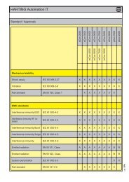
Railway specific products with NFF Classification: F1 and I2In addition to the standard demands of connectors, as definedin IEC 60 603-2, for example, market and application specificdemands and requirements are gaining increasing significance.In the railway engineering area the demands made on reliabilityand safety are particularly high, in order to ensure utmostpassenger safety in all instances. Especially in the case of routesinvolving a high share of tunnels that only offer limited escaperoute possibilities in the event of fire, the technical demands madeon the materials employed are very stringent.The matrix from NFF 16-102 shows how the combination of bothcharacteristics results in a classification. This matrix is definedby the contractor in each project put up for bidding. The matrixis geared to the type of train and course of the route, wherebyspecial attention is given to the number of tunnels. By complyingwith the high classifications I2 and F1, the designated standardssupplementing connectors according to IEC 60 603-2 can beused in all four defined groups and for all railway applications.According to NFF 16-102 the standard <strong>DIN</strong> connectors (I3, F3) areonly permissible for Group 1.GeneralinformationIn addition to the fire load, and/or the flammability of a material,the so-called smoke gas density is a key characteristic, which isdetermined based on the opacity and toxicity of the smoke gasemissions. The risk posed by the two characteristics can notbe defined in relationship to each other, which means that bothminimal inflammability as well as minimal smoke gas density mustbe fulfilled. Materials that meet both requirements are very rareand in many instances it is only possible to fully meet one of thetwo criteria.The French NFF 16-1<strong>01</strong> railway standard defines theserequirements precisely and presents a structure of applicationgroups by way of a matrix.NFF 16-1<strong>01</strong> classifies non-metallic materials used in rail vehiclesin terms of fire behavior, opacity and toxicity of smoke gasemissions in the event that the materials should burn.In order to enable the classification with regard to the deploymentof connectors, the following values must be applied:1. Fire behavior classClassification:I0 for I.O. ≥ 70 and no inflammation at 960 °CI1 for I.O. 45 - 69 and no inflammation at 960 °CI2 for I.O. 32 - 44 and no inflammation at 850 °CI3 for I.O. 28 - 31 and no afterburning at 850 °CI4 for I.O. ≥ 20NC not classifiedNote: The values are derived from specified test methodsdetermining the oxygen value (I.O.) and testing inflammability byway of a filament.2. Smoke development classificationClassification:F0 for I.F. ≤ 5F1 for I.F. 6 - 20F2 for I.F. 21 - 40F3 for I.F. 41 - 80F4 for I.F. 81 - 120F5 for I.F. > 120Diagram: Classification from NFF 16-102, April 1992The <strong>HARTING</strong> <strong>DIN</strong> Power and <strong>DIN</strong> Signal-Portfolio looks backon a highly successful track record in the railroad engineeringindustry. Typical application areas include – among many others- control, steering, monitoring components and modules on boardtrains, as well as signal technology components or the powersupply of electronic components.The extended range of connectors complying with the highestclassification according to NFF 16-1<strong>01</strong> and 16-102 considerablyreduce our customers’ development times: as the selectedconnectors are suitable for every stipulated hazard or risk class,they are ideal for realizing product platforms, and therefore finduse in every conceivable rail vehicle or railroad engineeringproject. This dispenses with the need for complex, product specificdevelopment work, at least in terms of selecting passive PCBinterfaces, while the technical approval process is streamlinedconsiderably.In order to facilitate rapid identification the additional, railwayspecific articles are designated accordingly on the product pages.Note: The values of the smoke index (I.F.) are derived fromspecified test methods by determining opacity (specific opticaldensity, opacity values), toxicity (critical gas concentration of CO,CO 2 , HCl, HBr, HCN, HF, SO 2 in smoke).00 .17
TerminationsGeneralinformationTHT soldering technologyProven over decades, standard soldering technologiesdeliver maximum stability and process reliability. Thesoldering pins of the connectors are inserted into thethrough-plated PCB holes and can then be solderedsimultaneously with other components in a wave solderingprocess.THT soldering technologySMC soldering technologyThe connector is inserted into through-plated PCB holessimilar to standard component assembly for processingwith SMC (Surface Mount Compatible) solderingtechnology. Insertion of these SMT components canbe automated by means of Pick & Place assembly inpreparation for a reflow soldering process together withthe surface-mounted component.This connection technology is characterized by highmechanical strength and is facilitated by a design that isspecially adapted to the reflow soldering process (hightemperaturematerials).SMC soldering technologyPress-in technologyThis solder-free connection technology is based on pressinmounting of a pin in a throughplated PCB hole. Theimplementation of a state-of-the-art, flexible press-fit zoneallows for the compensation of tolerances of PCB holesand meets high electrical and mechanical requirementsfor properties such as low press-in forces and high holdingforces.Press-in technology supports unlimited cost efficientprocessing, especially of pins with selective gold platingfor backplane bus systems.00 .18Press-in technologyYou will find more detailed information on the following pages.Wire wrap terminalsThis solder-free connection technology is based on a wire,which is wrapped with several turns onto a rectangularpost. When wires are correctly wrapped the connectionperforms with low resistance, mechanical strengthand high reliability, unaffected by normal climatic ortemperature change.
TerminationsCrimp terminalsGas-proof and the miniaturized contact technology aresynonymous with crimp technology. The flexible conductoris inserted into the crimp contact and is retained bycontrolled deformation. This technology is similar to a coldwelding process and provides maximum aging resistanceand mechanical resistance to shock and vibration. Crimpmachines facilitate the efficient, streamlined production ofsystem cable assemblies, and crimp technology can alsobe deployed for field assemblies using the correspondinghand crimp tools. The technical requirements for crimptechnology are standardized in IEC 60 352-2.Crimp terminalGeneralinformationIDC insulation displacement terminalsIDC (insulation displacement contact) technology facilitatesthe simple and safe termination of solid and flexibleconductors. With IDC technology, a blade cuts through thewire insulation and produces an elastic termination in asingle pass. This gas-proof connection provides maximumsafety even for the lowest currents and voltages. Technicalrequirements for IDC technology are standardized inIEC 60 352-3.Solder lug terminalsThe solder lug termination is the optimized solutionfor production of small lot sizes and prototypes. Evenwithout any special tooling a big variety of cables can beterminated to the cable connectors. The stripped wireis soldered individually by hand to the solder lug. Thistermination should however only be manufactured byexperienced specialists.IDC insulation displacement terminalsFaston blades terminalsThe faston blade termination is used for free wiring.Benefits are the high current carrying capacity (up to 15 A)and the easy possibility for variations.Cage clamp terminalsThe cage clamp terminal technology is used to terminateflexible and solid conductors by means of spring force.After the spring has been opened by an actuator element,the stripped conductor is simply inserted into the contactchamber. This connection technology requires minimumoperating expense and is characterized by its highfunctional safety. The springloaded connection also allowsthe termination of more than one wire per contact andexcels with high vibration and shock resistance.Cage clamp terminalsYou will find more detailed information on the following pages.00 .19
TerminationsGeneralinformationTHT soldering technologyThe term "soldering" is defined in <strong>DIN</strong> 8505:"Soldering is a method of connecting metallic materialsusing an additional melting metal, if necessary with the assistanceof a flux and/or protective gas. The melting temperatureof the solder must lie beneath the minimum meltingtemperature of the base metals being connected. Thesebase metals shall be tinned without melting themselves."Soft solders commonly used on electronic equipment are to<strong>DIN</strong> 1707-100. Todays lead free solders have a melting rangebetween 217 °C and 227 °C depending on the composition of thealloy. For soldering metallic materials the flux is defined in <strong>DIN</strong>EN 29 454-1. Tests are explained in <strong>DIN</strong> 8526. For soldering maleconnectors into printed circuit boards, see recommendations forsoldering on page 00.06.The components are positioned using pick-and-place machines.These automatic assembly machines differ according to whetherthe components are small, lightweight or bulky. Connectors areconsidered bulky (odd form) because of their comparatively heavyweight and large volume which makes them more difficult to grip.Furthermore, machines for odd form components must havehigher insertion power to fit the components into pcb holes, whichare filled with solder paste. As a rule, modern SMC productionlines are equipped with both types of machine, therefore the"Pin in Hole Intrusive Reflow" process generally entails no extrainvestment costs for the user.Conventional assembly process:SMC soldering technologyThe continuing trend towards miniaturisation hasrevolutionised the assembly of electronic components. For thepast 15 years, most components have been secured directlyto the pcb surface by means of Surface Mount Technology(SMT). By dispensing with drilled holes on the pcb, a spacesaving of up to 70 percent is achieved.1. Application of solder paste2. Positioning the components3. Positioning odd form components4. Reflow soldering5. Pressing in or partially dip soldering theconnector at the board edge6. Quality inspectionFig. 1:SMT board with connector for"Pin in Hole Intrusive Reflow" assembly“Pin in Hole Intrusive Reflow” assembly:1. Application of solder paste2. Positioning the components3. Positioning odd form components4. Reflow soldering5. Pressing in or partially dip soldering theconnector at the board edge6. Quality inspectionToday, typical components such as resistors, ICs, capacitors, andconnectors with straight terminal pins are almost exclusively fittedusing SMD (Surface Mount Device) technology in mass production.In contrast, angled SMD connectors at the edge of the board havenot been successful because of tolerance problems (co-planarity)and stresses during mating. Modified solder connectors forassembly with "Pin in Hole Intrusive Reflow" process offer a bettersolution. These can be mounted at low cost, utilising existing SMDproduction lines.00 .20“Pin in Hole Intrusive Reflow”In this process, the connector is inserted into plated through holesin a comparable way to conventional component mounting. Allother components can be assembled on the pcb surface.Fig. 2:Pick-and-place machine forodd form components(Courtesy of JOT Automation GmbH)
TerminationsSolder requirementsRequirements for the solder connectionApplication of solder pasteBefore the components are assembled, solder paste must beapplied to all the solder pads (for connecting surface-mountcomponents) and the plated through contacts (pcb holes for "Pinin Hole Intrusive Reflow" insertion). Usually a screen printingprocess is used for this purpose. A squeegee moves acrossthe pcb, which is masked with screens and presses the solderpaste into all unmasked areas. To ensure that the plated throughholes are completely filled, significantly more solder paste mustbe applied than traditional solder pads on the pcb surface. Therequired quantity can be set exactly via several parameters.As an alternative to screen printing, the solder paste can beapplied by means of a dispenser. A high- precision robot movesthe dispenser to all required positions on the pcb. The dispensingmethod is particularly suitable for small pcb’s or applicationswhich demand high precision and flexibility in dispensingvolumes.There are numerous scientific studies dealing with calculation ofthe required quantity of solder paste. These studies use variousparameters, e.g. the shrinking factor of the paste during solderingor the thickness of the screens used for masking the pcb. Sincesuch calculation methods are complicated to apply, the followingrule of thumb has proved valuable in practice:V Paste = 2(V H – V P )in which:V Paste= Required volume of solder pasteGeneralinformationV HV P= Volume of the plated through hole= Volume of the connector terminationin the holeComment: the multiplier “2” compensates for solder pasteshrinkage during soldering. For this purpose, it wasassumed that 50 % of the paste consists of the actualsolder, the other 50 % being soldering aids.At the beginning of a new production batch, the processparameters, such as quantity of solder paste and solderingtemperature, can be set by interpreting simple cross-sectionsof the soldered connection. A reliable measure for achievingoptimum parameters is the quantity of solder required to fill thehole. In soldered connections of high quality, the holes are filledto between 75 % and 100 %.Volume of solder pasteConnectorterminationpcbFig. 3: Dispenser in operationFig. 4: Plated through hole with connector termination00 .21
TerminationsRequirements for SMC connectors<strong>HARTING</strong> SMC technologyGeneralinformationSMC (Surface Mount Compatible) connectors have to withstandtemperatures of up to 240 °C in the reflow oven for 10 to 15 seconds.Therefore, the moulding must be made from a dimensionallystable plastic which expands at the same rate as the pcbmaterial when subjected to heat.The length of the connector contacts should be such that theyprotrude by no more than 1.5 millimetres after insertion to the pcb.Each contact collects solder on its tip as it penetrates the solderpaste in the hole. So if the contact was too long, this solder wouldno longer be able to reflow back into the plated through hole bycapillary action during the soldering process, therefore the qualityof the soldered connection would suffer as a result.<strong>HARTING</strong> offers its customers a complete system concept for integratingSMC technology into existing production lines. We manufacturea wide range of SMC connectors (3 and 5 row) in compliancewith IEC 60603-2, D-Sub connectors in compliance withIEC 60807 and connectors from the har-mik® series with contactspacing of 1.27 millimetres. In addition, <strong>HARTING</strong> supports themarket with packaging and processing concepts, which have beendeveloped in collaboration with renowned manufacturers of SMCsoldering and assembly plants.You will find more detailed information in our SMC catalogue,as well as in our hard metric connectors catalogue.Connector design must permit both automatic assembly withpick-and-place machines and manual positioning for test and preproductionbatches. It is also important for the packaging of theconnectors to be suitable for automated assembly. Experienceshows that deep-drawn film and reel packaging fed into the pickand-placemachines with the aid of a conveyor system is particularlysuitable.Advantages of the “Pin in Hole IntrusiveReflow” process:• Partial dip soldering or press fitting is nolonger required• <strong>Complete</strong> compatibility with Surface MountTechnology• <strong>Complete</strong> integration into the automatedassembly process• Reduced floor space in the production plant• As a rule, no additional investment costs00 .22Fig. 5: <strong>HARTING</strong> connector mounted in a tape readyfor placement using an odd form assembly station.
TerminationsPress-in technologySolderless termination for connectors has proven to be reliable fordecades. Today the use of press-in connectors encompasses allfields of electrical and electronical applications.GeneralinformationPressing of electrical components, mainly connectors, is characterisedthrough the matching of the connector pin and the platedthrough hole of the pcb. Whereas the desired electrical characteristicscan be attained relatively independant from the design of thepress-in zone, the mechanical characteristics of the press-in zoneare crucial for the reliable assembly of connectors where pcb'shave different surfaces.bus board withpress-in connectorsAlthough the scope of requirements at the press-in process isgenerally defined in time-tested specifications, the novel press-inzones should offer an optimal handling and a reliable termination.Essentially, this is guaranteed through the design of the press-inzone and the meticulous observance of tolerances. <strong>HARTING</strong> hasbeen using FEM simulations for the calculation and optimisation ofpress-in zones for a long period of time. This expertise allows us tosimulate various pcb configurations very accurate.Benefits of the press-in technology● Thermal shocks associated with the soldering process and therisk of the board malfunction are avoided.● No need for the subsequent cleaning of the assembled pcb’s● Additional wrap connections are made possible by usingconnectors with long pins● Unlimited and efficient processing of partially gold-plated pinsfor rear I/O - manual soldering is no longer necessary!FEM simulationof the needle eyepress-in zone00 .23
TerminationsPress-in technologyPhase 1GeneralinformationThe processing of press-in connectors can be divided into 3 phases,containing both mechanical and metallurgical operations:1. Centering and placing of the termination pinsPress die(Flat rock)The centering of connectors before pressing is important inorder to prevent damage to the pcb and the termination pins.Centering can be omitted when connectors are pressed usinga flat rock die.<strong>HARTING</strong> offers insert blocks for male connectors to makethe centering of connectors unnecessary.Insert blockConnectorMultilayerpcb2. Pressing in the pinsPhase 2In the press-in process the insertion force is continuouslytransformed into compression force. The resulting frictionfrees the contacting bars of insulating films. Superfluousplating (tin) is transferred within the plated through hole. Agas-tight connection of fresh non-oxidised metal surfaces isobtained.3. Obtaining the final positionThe press-in operation should be terminated as soon asthe connector obtains its final position on the pcb to avoidunnecessary compressive stress. The press-in machinesof <strong>HARTING</strong> feature automatic termination of the pressinoperation independant of pcb thickness and surfaceproperties.Phase 3The entire dynamic press-in process is characterised throughchanges of the press-in force that can be statistically evaluated.<strong>HARTING</strong> records the changes of force with the help of specialsoftware. This is an important step towards permanent processcontrol and documented manufacturing data.00 .24The -zone is based on the industry renowned needle eyetechnology. Its special design allows for compensation of tolerancesof pcb surface properties (eg. superfluous tin plating). The excessivematerial is displaced within the plated through hole, whereby a gastightand corrosion resistant electrical connection is assured.
TerminationsRecommended configuration of platedthrough holesDue to the high deformation resistance and resilience ofcontacts, they can be easily and repeatedly removed in case ofrepairs without impairment to their functioning.is extremely versatile and offers a reliable electricalcontact, therefore it is especially well suited for applications withthese surfaces.Please contact us for detailed test reports.GeneralinformationIn addition to the hot-air-level (HAL) other pcb surfaces aregetting more important. Due to their different properties, such asmechanical strength and coefficient of friction we recommend thefollowing configuration of pcb through holes.Tin-lead plated Hole-Ø 1.15 ±0.025 mmPCB Cu min. 25 µm(HAL) Sn max. 15 µmacc. EN 60 352-5 Plated hole-Ø 0.94-1.09 mmChemical Hole-Ø 1.15 ±0.025 mmtin-plated PCB Cu min. 25 µmSn min. 0.8 µmPlated hole-Ø 1.00-1.10 mmAu / Ni plated PCB Hole-Ø 1.15 ±0.025 mmCu min. 25 µmNi 3-7 µmAu 0.05-0.12 µmPlated hole-Ø 1.00-1.10 mmSilver plated PCB Hole-Ø 1.15 ±0.025 mmCu min. 25 µmAg 0.1-0.3 µmPlated hole-Ø 1.00-1.10 mmOSP Hole-Ø 1.15 ±0.025 mmcopper plated PCB Cu min. 25 µmPlated hole-Ø 1.00-1.10 mmPCB board thickness: ≥ 1.6 mmSn (HAL)chem. SnAuAgpure CuPdSketch:press-in zonein plated through holeHole-ØDiameterplated through hole1.09 mm(max.)M 29:1Diameterplated through hole0.99-1.00 mm(nominal)M 29:1Diameterplated through hole0.92-0.94 mm(min.)M 29:1IIIIIIIM 58:1IM 58:1IM 58:1IIIIIIM 58:1M 58:1M 58:1CuIIICross section of a pcb 2.4 mm thick with various hole diameterspcb holesfor press-inprocess in acc.to EN 60 352-5e. g. SnPlated hole-Ø00 .25
TerminationsCrimp terminalsGeneralinformationA perfect crimp connection is gastight and therefore corrosion free. It isequivalent to a cold weld of the connected parts. For this reason, majorfeatures in achieving high quality crimp connections are the design ofthe crimping areas of the contact and of course the crimping tool it self.Wires to be connected must be carefully matched to the correct sizeof crimp contacts. If these basic requirements are met, users will beassured of highly reliable connections with a low contact resistanceand a high resistance against corrosion.Crimp cross-sectionThe economical and technical advantages are:● Constant contact resistance as a result of an unvariable crimpconnection quality● Corrosion free connections as a result of cold weld action● Preparation of harnessing with crimp contacts already fitted● More economic cable connectionRequirements for crimp connections are set out in <strong>DIN</strong> IEC 60 352-2.Pull out force of stranded wireThe main criterion by which to judge the quality of a crimp connectionis the retention force achieved by the wire conductor in the terminalsection of the contact. <strong>DIN</strong> IEC 60 352, part 2, defines the extractionforce in relation to the cross-section of the conductor. When fitted using<strong>HARTING</strong> crimping tools and subject to their utilization in an approvedmanner, our crimp connectors comply with the required extractionforces.Tensile strength of crimped connectionsConductor cross-sectionTensile strengthmm² AWG N0.05 30 60.08 28 110.12 26 150.14 180.22 24 280.25 320.32 22 400.5 20 600.75 850.82 18 9<strong>01</strong>.0 1081.3 16 1351.5 1502.1 14 2002.5 2303.3 12 2754.0 3105.3 10 3556.0 3608.4 8 37<strong>01</strong>0.0 380Extract from <strong>DIN</strong> IEC 60 352-2, Amend. 2, table IVCrimping toolsCrimping tools (hand operated or automatic) are carefully designed toguarantee a symmetrical deformation of the crimping area of thecontact and the wire through the high pressure forming parts of thetool. The locator automatically engages the crimp contact and the wireat the correct point in the tool. The wire insulation can also be includedas a secondary feature of some crimp contacts to care for additionalmechanical strength.Wire gauge (mm²)The ratchet in the tool performs 2 functions:Locator➀ It prevents insertion of the crimp into the tool for crimping beforethe jaws are fully open➁ It prevents the tool from being opened before the crimping actionis completed00 .26A quality crimp connection can be achieved with this crimping system.The adjacent sketches show important features of the <strong>HARTING</strong> handcrimping tool.The <strong>HARTING</strong> automatic crimping tool uses bandoliered contacts.The machine strips insulation from the wire and then crimps the contact.Both the crimping area and the insulation support are independentlyadjustable to facilitate the use of any wire type with dimensions withinthe stated crimp capacity.
TerminationsWire wrap terminalsThis technique permits high wiring density and takes over where othertechniques would take up too much real estate. As a result of thisprocess, there is a great time saving factor and cost per connection isrelatively low when large numbers of connections are to be made.When wires are correctly wrapped onto a precision manufacturedrectangular post produced to the recommended specifications, onecan state the following:GeneralinformationA low resistance, mechanically strong and highly reliable connectionis made which is unaffected by normal climatic or temperaturechanges.Production of wrapped connections and associated material are de finedin <strong>DIN</strong> EN 60 352-1.Standard wrapWrapping techniquesStandard wrapOnly the non-insulated part of the wire is wrapped around thepost. This means that the size of the wrapped connection iskept to the very minimum.Modified wrapThe top part of the wrapped connection is made using thecable conductor as stated above but an extra turn is made atthe bottom. For this turn insulation is also wrapped around thepost to give a great mechanical strength to the joint and alsoto provide insulation between adjacent posts.Valid forstandard wrapDimensionof wire wrappost [mm]Lengthof wire wrappost [mm]Wire diameter [mm]0.25 0.32 0.40 0.50 0.65 0.80 1.00max. allowed wire Ø incl. wire insulation [mm]0.70 0.90 1.17 1.27 1.32 1.50 1.78min. necessary turns per wrapconnection (for non-insulated wire)7 7 6 5 4 4 4possible wrap connectionsper wrap post0.6 x 0.6 13 6 5 4 4 4 3 20.6 x 0.6 17 8 6 6 5 5 4 31 x 1 20 10 7 7 6 6 5 41 x 1 22 11 8 7 7 6 5 4Table 00.05Wrapping toolsTo produce quality wrapped connections one must use a specialwrapping tool, which can be pneumatic, electric or hand operated.Such tools have interchangeable wrapping heads and sleeves to suitthe particular size of the wrap post being used.The choice of accessories for these wrapping tools depends from thewrapping technique, the size of the wrap post itself and the conductorand insulation diameters of the wire.The adjacent tables show the maximum amount of wrapped connectionsthat can be placed on the wire wrap post (in acc. to IEC 60352-1).Modified wrapValid formodified wrapDimensionof wire wrappost [mm]Table 00.06Lengthof wire wrappost [mm]Wire diameter [mm]0.25 0.32 0.40 0.50 0.65 0.80 1,00max. allowed wire Ø incl. wire insulation [mm]0.70 0.90 1.17 1.27 1.32 1.50 1.78min. necessary turns per wrapconnection (for non-insulated wire)7 7 6 5 4 4 4possible wrap connectionsper wrap post0.6 x 0.6 13 4 3 2 2 2 2 10.6 x 0.6 17 5 4 3 3 3 2 21 x 1 20 6 4 4 3 3 3 21 x 1 22 6 5 4 4 4 3 200 .27
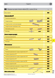
Directory chapter <strong>01</strong> – <strong>DIN</strong> Signal (up to 2 A)Types B, 2B, 3B, C, 2C, 3C, M, M invers, Q, 2Q, R, 2RPageTechnical characteristics . . . . . . . . . . . . . . . . . . . . . . . . . . . . . . . . . . . . . . . . . . <strong>01</strong>.10Type B connectors . . . . . . . . . . . . . . . . . . . . <strong>01</strong>.11Type 2B connectors . . . . . . . . . . . . . . . . . . . <strong>01</strong>.16<strong>DIN</strong> Signalup to 2 AType 3B connectors . . . . . . . . . . . . . . . . . . . <strong>01</strong>.18Type C connectors . . . . . . . . . . . . . . . . . . . . <strong>01</strong>.20Type 2C connectors . . . . . . . . . . . . . . . . . . . <strong>01</strong>.27Type 3C connectors . . . . . . . . . . . . . . . . . . . <strong>01</strong>.32Special contacts type M . . . . . . . . . . . . . . . . <strong>01</strong>.36Type M connectors . . . . . . . . . . . . . . . . . . . <strong>01</strong>.41Type M-flat connectors . . . . . . . . . . . . . . . . <strong>01</strong>.43Type M invers connectors . . . . . . . . . . . . . . <strong>01</strong>.44Type R, RM, R (HE 11) connectors . . . . . . . <strong>01</strong>.46Type Q, 2Q and 2R connectors . . . . . . . . . . <strong>01</strong>.52Pin shroud, adapter . . . . . . . . . . . . . . . . . . . . . . . . . <strong>01</strong>.57Application examples . . . . . . . . . . . . . . . . . . . . . . . . . . . . . . . . . . . . . . . . . . . . . <strong>01</strong>.60<strong>01</strong> .<strong>01</strong>
Technical characteristicsTypes B, 2B, 3B, C, 2C, 3C, M, M invers,Q, 2Q, R, R (HE 11), 2R<strong>DIN</strong> Signalup to 2 ANumber of contacts 16-96Contact spacing (mm) 2.54Working current2 A max.see current carrying1 A with insulation displacementcapacity chart40 A max. type MClearance³ 1.2 mmCreepage³ 1.2 mmWorking voltageThe working voltage also depends according to the safety regulationson the clearance and creepage of the equipmentdimensions of the pcb itself, Explanations see chapter 00and the associated wiringTest voltage U r.m.s.Contact resistanceInsulation resistance1 kV£ 15 mW for wire wrap and solderconnection£ 20 mW including crimp connection³ 10 12 W for standard articles³ 10 11 W for special NFF articles (withpart-no. ending 222)Temperature range – 55 °C … + 125 °CThe higher temperature limit – 40 °C … + 105 °Cincludes the local ambient for press-in connectorand heating effects of thecontacts under loadDuring reflow soldering max. + 240 °C for 15 sfor SMC connectorsDegree of protection for crimp terminal IP 20according to <strong>DIN</strong> 40 050Electrical terminationMale and female connectorSolder pins for pcb connectionsØ 1.0 ± 0.1 mmaccording to IEC 60 326-3wrap posts 0.6 x 0.6 mmdiagonal 0.79-0.86 mmCrimp terminal 0.09-0.5 mm²Insulation displacementconnection AWG 28/7Compliant press-interminationsPCB thickness³ 1.6 mmRecommended PCB holes for See recommendation page 00.25press-in technology in acc. to EN 60 352-5Current carrying capacityThe current carrying capacity is limited by maximum temperature ofmaterials for inserts and contacts including terminals. The currentcapacity curve is valid for continuous, non interrupted current loadedcontacts of connectors when simultaneous power on all contacts isgiven, without exceeding the maximum temperature.Control and test procedures according to <strong>DIN</strong> IEC 60 512Working currentAmbient temperaturePin shroud for female connectorswith 0.6 x 0.6 mm pinsA secure interfacing system for signals from the rear of 19” racksto connectors with wrap posts 0.6 x 0.6 mm is possible with theuse of a pin shroud.The pin shroud protects the wrap posts on the rear side of the rackand can be screwed to the printed circuit board.After assembly the rear ends of the wire wrap posts become themating areas of the type C resp. type 2C male connector.This system can now accept:● female connectors type C● female connectors type 2C● female connectors type R● female connectors type 2R<strong>01</strong> .10Insertion and withdrawal force 16way £ 15 N20way £ 20 N30way £ 30 N32way £ 30 N48way £ 45 N64way £ 60 N96way £ 90 NMaterialsMouldingsContactsContact surfaceContact zoneThermoplastic resin,glass-fibre filled, UL 94-V0Copper alloySelectively plated according toperformance level 1)1)Explanation performance levels see chapter 00Mating conditions see chapter 00The locking levers provide security for the mated connectors. Fastand simple disconnection is possible (see application examples,pages <strong>01</strong>.60 ff.Fitting and removing crimp contactssee technical characteristics chapter 02
<strong>DIN</strong> 41 612 · Type BNumber of contacts64, 32Male connectorsNumber ContactIdentification of contacts arrangementMale connectorwith angledsolder pins64Part No. Performance levels according to IEC 60 603-2. Explanation chapter 003 2 109 02 164 7921 09 02 164 6921 09 02 164 292109 02 164 6921 222 f)b) 09 02 364 6921 b)c) 09 02 664 6921 c)<strong>DIN</strong> Signalup to 2 A32 09 02 132 7921 09 02 132 6921 09 02 132 2921c) 09 02 632 6921 c)32 09 02 132 7931 09 02 132 6931 09 02 132 2931b)09 02 332 6931 b)62 + 2 ▲ 09 02 164 6951SMC64 09 02 164 7919 d) 09 02 164 6919 d)Male connectorwith straightsolder pins64 09 02 164 7922 09 02 164 6922 09 02 164 292232 09 02 132 7922 09 02 132 692232 09 02 132 693262 + 2 ▲ 09 02 164 6952 09 02 164 2952SMC64 09 02 164 6920 d)DimensionsAngledsolder pinsStraightsolder pinsBoard drillingsMounting sideCross section of solderterminations▲Male connectors with 2 leading contacts [(0.8 mm) pos. a1 anda32]. Lagging pins row b on request.Other contact arrangements on requestb)Connectors with snap-in clips see chapter 00Cross area (A) of contacts row a, b:A = 0.29 - 0.33 mm²Dimensions in mmc)Connectors with coding see chapter 00d) CTI > 400f) Railway classification NFF 16-1<strong>01</strong>, Smoke index: F1,Flammability class: I2<strong>01</strong> .11
<strong>DIN</strong> 41 612 · Type BNumber of contacts64Female connectors<strong>DIN</strong> Signalup to 2 AIdentificationFemale connectorwith solder pins2.9 mmNumber Contactof contacts arrangementPart No. Performance levels according to IEC 60 603-2. Explanation chapter 003 2 109 02 264 6824 09 02 264 282464 b) 09 02 464 6824 b)c) 09 02 764 6824 c)SMC64 09 02 264 6841 d)Female connectorwith solder pins4.5 mm6409 02 264 6825 09 02 264 282509 02 264 6825 222 f)09 02 464 6825 b)09 02 764 6825 c)Female connectorwith solder pins13 mmSMC64 09 02 264 6829 d)64 09 02 264 6421Female connectorwith press-in pins4.5 mm64Performance level 3on request09 02 264 6850 09 02 264 285009 02 264 6850 222 f)Female connectorwith press-in pinswithout flange5.3 mmFemale connectorwith press-in pins13.2 mm64 09 02 264 687064 09 02 264 6861 a)Female connectorwith wrap posts 1)13 mm64 09 02 264 6821<strong>01</strong> .12Female connectorwith solder lugs5.2 mm1) To be used only for wire wrap terminationa) Wrap posts selectively gold plated (performance level 3)b) Connectors with snap-in clips see chapter 00c) Connectors with coding see chapter 0064 09 02 264 6823d)CTI > 400f) Railway classification NFF 16-1<strong>01</strong>, Smoke index: F1,Flammability class: I2Other contact arrangements on request
<strong>DIN</strong> 41 612 · Type BNumber of contacts64Female connectorsIdentification Drawing Dimensions in mmDimensionsrow2,9 - 0,58,1 - 0,2a2.94.5134.55.313.2135.2Solder pinsPress-in pinsWrap postsSolder lugs<strong>DIN</strong> Signalup to 2 ApositionPanel cut outBoard drillingsMounting sideall holesYpositionrowYSolder 1 ± 0.1Press-insee recommendationpage 00.25Identification strips for female connectors with wrap posts 09 02 000 9939Cross section ofsolder terminationsQPa P Q A2.9 0.75 –0.05 0.30 ±0.<strong>01</strong> 0.20 - 0.23 mm²4.5 0.75 –0.05 0.30 ±0.<strong>01</strong> 0.20 - 0.23 mm²13 0.60 –0.02 0.60 –0.02 0.33 - 0.38 mm²Cross area (A) of contacts<strong>01</strong> .13
<strong>DIN</strong> 41 612 · Type BNumber of contacts64Female connectors<strong>DIN</strong> Signalup to 2 ANumberIdentification of contacts Part No. Drawing Dimensions in mmFemale connectorfor insulationdisplacementCable 1Performance level 2 1)64 09 02 264 6828Performance level 3 1)09 02 264 7828Cable 1 to contact 1 bContact arrangementCable 1View from termination sideStrain relief (metal)09 03 000 9940Panel cut outFlat cableAWG 28/7grey2)Termination areaspacing = 508 mmgreygreycolour codedtwisted pair 2)Round flat cable 3)withscreening30.48 m100.00 m30.48 m30.48 m30.48 m100.00 m64 09 18 064 70<strong>01</strong>64 09 18 064 700464 09 18 064 700564 09 18 064 700664 09 18 064 700764 09 18 064 7<strong>01</strong>0Important: alwaysstore reels verticallyWire (tinned)CuGauge AWG 28/7 0.089 mm²Insulation material as per UL style PVCEdge mark onfirst conductorAWG 28/73)Termination areaspacing = 100 mmgrey<strong>01</strong> .14withoutscreeningBench pressBase plateCable cutterSpare partsBladeCutting plate30.48 m100.00 m64 09 18 064 700864 09 18 064 7<strong>01</strong>109 99 000 <strong>01</strong>1409 99 000 <strong>01</strong>5009 99 000 <strong>01</strong>1609 99 000 <strong>01</strong>7909 99 000 <strong>01</strong>80Further components and accessories for insulation displacement see interface catalogue, chapter 4<strong>01</strong>)acc. to IEC 60 603-2
<strong>DIN</strong> 41 612 · complementary type 2BNumber of contacts32, 16Male connectors<strong>DIN</strong> Signalup to 2 AIdentificationMale connectorwith angledsolder pinsNumber Contactof contacts arrangementPart No. Performance levels according to IEC 60 603-2. Explanation chapter 003 2 109 22 132 7921 09 22 132 6921 09 22 132 292132 09 22 132 6921 222 f)b) 09 22 332 6921 b)SMC3209 22 132 6919 d)b) 09 22 332 6919 b)d)16 09 22 116 692116 09 22 116 7931 09 22 116 693130 + 2 ▲ 09 22 132 6951Male connectorwith straightsolder pinsSMC32 09 22 132 7922 09 22 132 6922 09 22 132 292232 09 22 132 6920 d)DimensionsrowpositionAngledsolder pinsStraightsolder pinsBoard drillingsMounting sideall holespositionCross section ofsolder terminationsrowCross area (A) of contactsrow a, b: A = 0.29 - 0.33 mm²<strong>01</strong> .16▲Male connectors with 2 leading contacts [(0.8 mm) pos. a1 anda16]. Lagging pins row b on request.b)Connectors with snap-in clips see chapter 00d)CTI > 400f) Railway classification NFF 16-1<strong>01</strong>, Smoke index: F1,Flammability class: I2Other contact arrangements on requestDimensions in mm
<strong>DIN</strong> 41 612 · complementary type 2BNumber of contacts32Female connectorsIdentificationFemale connectorwith solder pins2.9 mmSMC4.5 mm13 mmFemale connectorwith wrap posts 1)13 mmFemale connectorwith press-in pins4.5 mmDimensionsSMCNumber Contactof contacts arrangement32Part No. Performance levels according to IEC 60 603-2. Explanation chapter 003 2 109 22 232 6824b)09 22 432 6824 b)32 09 22 232 6841 d)09 22 232 682532 09 22 232 6825 222 f)b) 09 22 432 6825 b)32 09 22 232 6829 d)Performance level 332on request09 22 232 642132 09 22 232 682132 09 22 232 6850Performance level 1on request<strong>DIN</strong> Signalup to 2 A8,1 - 0,22,9 - 0,5rowpositiona2.94.513134.5Solder pinsWrap postsPress-in pinsBoard drillingsMounting sideall holesYpositionYSolder 1 ± 0.1Press-insee recommendationpage 00.25rowCross sectionof solder terminationssee page <strong>01</strong>.131)To be used only for wire wrap terminationb)Connectors with snap-in clips see chapter 00d)CTI > 400f) Railway classification NFF 16-1<strong>01</strong>, Smoke index: F1,Flammability class: I2Other contact arrangements on requestDimensions in mm<strong>01</strong> .17
<strong>DIN</strong> 41 612 · complementary type 3BNumber of contacts20Male connectors<strong>DIN</strong> Signalup to 2 AIdentificationMale connectorwith angledsolder pinswith fixing flangeNumber Contactof contacts arrangementPart No. Performance levels according to IEC 60 603-2.3 2 120 09 24 120 6921with fixing flange, SMCwithout fixing flange20 09 24 120 6919 d)Performance level 3on request20 09 24 120 6571Performance level 1on requestwithout fixing flange, SMC20 09 24 120 6579 d)Dimensionswith fixing flangewithout fixing flangerowmounting hole center linepositionBoard drillingsMounting sideall holespositionCross section ofsolder terminationsrowCross area (A) of contactsrow a, b: A = 0.29 - 0.33 mm²<strong>01</strong> .18d) CTI > 400Dimensions in mm
<strong>DIN</strong> 41 612 · complementary type 3BNumber of contacts20Female connectorsIdentificationFemale connectorwith solder pins 2.9 mmwith fixing flangewith fixing flange, SMCwithout fixing flange, SMCNumber Contactof contacts arrangementPart No. Performance levels according to IEC 60 603-2.3 2 120 09 24 220 682420 09 24 220 6841 d)20 09 24 220 6414 d)<strong>DIN</strong> Signalup to 2 AFemale connectorwith solder pins 4.5 mmwith fixing flangeFemale connector withpress-in pins 4.5 mmwith fixing flangewithout fixing flangePerformance level 3on request20 09 24 220 682520 09 24 220 685020 09 24 220 6870Performance level 1on requestDimensionswith fixing flangewithout fixing flangerowpositiona2.94.54.5solder pinspress-in pinsBoard drillingsMounting sideall holesYpositionYSolder 1 ± 0.1seePress-in recommendationpage 00.25Cross section ofsolder terminationsd) CTI > 400rowCross area (A) of contactsrow a, b, c: A = 0.20 - 0.23 mm²Dimensions in mm<strong>01</strong> .19
<strong>DIN</strong> 41 612 · Type CNumber of contacts96, 64, 32Male connectors<strong>DIN</strong> Signalup to 2 AIdentificationMale connectorwith angledsolder pinsNumber Contactof contacts arrangementPart No. Performance levels according to IEC 60 603-2. Explanation chapter 003 2 109 03 196 7921 09 03 196 6921 09 03 196 292109 03 196 6921 222 f) 09 03 196 2921 222 f)96 b) 09 03 396 7921 b) b) 09 03 396 6921 b) b) 09 03 396 2921 b)c) 09 03 696 6921 c) c) 09 03 696 2921 c)09 03 696 6921 222 c)f)SMC09 03 196 6919 d) 09 03 196 2919 d)96 09 03 396 6919 b)d) 09 03 396 2919 b)d)09 03 696 6919 c)d)6409 03 164 7921 09 03 164 6921 09 03 164 292109 03 164 6921 222 f) 09 03 164 2921 222 f)b) 09 03 364 7921 b) b) 09 03 364 6921 b) b) 09 03 364 2921 b)c) 09 03 664 6921 c) c) 09 03 664 2921 c)SMC6409 03 164 6919 d) 09 03 164 2919 d)09 03 364 6919 b)d) 09 03 364 2919 b)d)3209 03 132 7921 09 03 132 6921 09 03 132 2921b) 09 03 332 7921 b) b) 09 03 332 6921 b) b) 09 03 332 2921 b)09 03 196 7951 09 03 196 6951 09 03 196 295194 + 2 ▲ b) 09 03 396 6951 b)SMC94 + 2 ▲ 09 03 396 6918 b)d)62 + 2 ▲ 09 03 164 7951 09 03 164 6951 09 03 164 2951SMC62 + 2 ▲ 09 03 164 2918 d)Male connectorwith straightsolder pins96 09 03 196 7922 09 03 196 6922 09 03 196 2922SMC96 09 03 196 6920 d)<strong>01</strong> .20▲Male connectors with 2 leading contacts [(0.8 mm) pos. a1 anda32]. Lagging pins row b on request.b)Connectors with snap-in clips see chapter 00c)Connectors with coding see chapter 0064 09 03 164 7922 09 03 164 6922 09 03 164 2922d)CTI > 400f) Railway classification NFF 16-1<strong>01</strong>, Smoke index: F1,Flammability class: I2
<strong>DIN</strong> 41 612 · Type CNumber of contacts96, 64, 32Male connectorsDimensions<strong>DIN</strong> Signalup to 2 AStraightsolder pinsAngledsolder pinsBoard drillingsMounting sideall holespositionrowCross sectionof solderterminationsCross area (A) of contacts row a, b, c: A = 0.29 - 0.33 mm²1)Recommendation for variants with clip: Drillings can be enlarged up to 3.1 mm ø to reduce standard mounting forceDimensions in mm<strong>01</strong> .21
<strong>DIN</strong> 41 612 · Type CNumber of contacts96, 64, 32Female connectors<strong>DIN</strong> Signalup to 2 AIdentificationFemale connectorwith solder pins2.9 mmNumber Contactof contacts arrangement96Part No. Performance levels according to IEC 60 603-2. Explanation chapter 003 2 109 03 296 7824 09 03 296 6824 09 03 296 282409 03 296 6824 222 f)09 03 496 6824 b) 09 03 496 2824 b)09 03 796 6824 c)SMC96 09 03 296 6841 d)6409 03 264 7824 09 03 264 6824 09 03 264 282409 03 264 6824 222 f)09 03 464 6824 b) 09 03 464 2824 b)09 03 764 6824 c)SMC64 09 03 264 6841 d)32 09 03 232 7824 09 03 232 6824 09 03 232 2824Female connectorwith kinkedsolder pins 1)2.9 mm96 09 03 296 7855 09 03 296 6855 09 03 296 285564 09 03 264 7855 09 03 264 6855 09 03 264 285532 09 03 232 7855 09 03 232 6855 09 03 232 2855Female connectorwith solder pins4.5 mmSMC09 03 296 7825 09 03 296 6825 09 03 296 282509 03 296 6825 222 f) 09 03 296 2825 222 f)96 b) 09 03 496 7825 b) 09 03 496 6825 b)96 09 03 296 6829 d)09 03 796 6825 c) 09 03 796 2825 c)09 03 796 6825 222 c)f)09 03 264 7825 09 03 264 6825 09 03 264 282564 b) 09 03 464 7825 b) 09 03 464 6825 b)09 03 764 6825 c)SMC64 09 03 264 6829 d)32 09 03 232 7825 09 03 232 6825 09 03 232 2825Female connectorwith kinkedsolder pins 1)4.5 mm96 09 03 296 7845 09 03 296 6845 09 03 296 284564 09 03 264 7845 09 03 264 6845 09 03 264 2845<strong>01</strong> .22Female connectorwith solder pins13 mm1)Kinked pins for fixing the connector onto the pcb see chapter 00b)Connectors with snap-in clips see chapter 00c)Connectors with coding see chapter 0032 09 03 232 7845 09 03 232 6845 09 03 232 284509 03 296 642196 09 03 796 6421 c)64 09 03 264 642109 03 764 6421 c)32 09 03 232 642109 03 732 6421 c)d) CTI > 400f) Railway classification NFF 16-1<strong>01</strong>, Smoke index: F1,Flammability class: I2
<strong>DIN</strong> 41 612 · Type CNumber of contacts96, 64, 32Female connectorsIdentification Drawing Dimensions in mmDimensions<strong>DIN</strong> Signalup to 2 A10,6 - 0,22,9 - 0,5rowpositionb ^= Length of kinked pinsa b2.9 2.754.5 4.3513 –Solder pinsBoard drillingsMounting sideall holespositionrowCross section ofsolder terminationsQPa P Q A2.9 0.75 –0.05 0.30 ±0.<strong>01</strong> 0.20 - 0.23 mm²4.5 0.75 –0.05 0.30 ±0.<strong>01</strong> 0.20 - 0.23 mm²13 0.60 –0.02 0.60 –0.02 0.33 - 0.38 mm²Cross area (A) of contactsDimensions in mm<strong>01</strong> .23
<strong>DIN</strong> 41 612 · Type CNumber of contacts96, 64, 32Female connectors<strong>DIN</strong> Signalup to 2 AIdentificationFemale connectorType Cwith press-in terminations4.5 mmNumber Contactof contacts arrangement96Part No. Performance levels according to IEC 60 603-2. Explanation chapter 003 2 109 03 296 7850 09 03 296 6850 09 03 296 285009 03 296 6850 222 f) 09 03 296 2850 222 f)09 03 796 6850 c)09 03 796 6850 222 c)f)64 09 03 264 7850 09 03 264 6850 09 03 264 285032 09 03 232 7850 09 03 232 6850 09 03 232 285<strong>01</strong>3.2 mm966409 03 296 685109 03 296 6861 l09 03 264 685109 03 264 6861 l17 mm9609 03 296 685209 03 296 6862 lDimensions10,6 - 0,22,9 - 0,5rowpositiona4.513.217Press-in pinsBoard drillingsMounting sideall holes1)positionrow<strong>01</strong> .24lWrap posts for interfacing selectively gold plated(performance level 3)Other contact arrangements on request1)refer to recommended configuration of pcb holes, see page 00.25c)Connectors with coding see chapter 00f) Railway classification NFF 16-1<strong>01</strong>, Smoke index: F1,Flammability class: I2Dimensions in mm
<strong>DIN</strong> 41 612 · Type CNumber of contacts96, 64Female connectorsIdentificationFemale connectorwith wrap posts 2)13 mmNumber Contactof contacts arrangementPart No. Performance levels according to IEC 60 603-2. Explanation chapter 003 2 109 03 296 682196c)09 03 796 6821 c)2)09 03 296 6878 1)<strong>DIN</strong> Signalup to 2 AFemale connectorwith solder lugsa + c 5.2 mmb 7.7 mm09 03 264 682164 09 03 764 6821 c)9664Performance level 3on request2)09 03 264 6878 1)09 03 296 682309 03 796 6823 c)09 03 264 682309 03 764 6823 c)Performance level 1on requestDimensions wrap posts solder lugswrap postsrowsolder lugspositionPanel cut outIdentification strips for femaleconnectors with wrap posts09 03 000 99391)Wrap posts for interfacing, selectively gold-plated (performance level 3)2)To be used only for wire wrap termination. Solder versions see page <strong>01</strong>.22c)Connectors with coding see chapter 00Dimensions in mm<strong>01</strong> .25
<strong>DIN</strong> 41 612 · Type CNumber of contacts64Female connectors<strong>DIN</strong> Signalup to 2 ANumberIdentification of contacts Part No. Drawing Dimensions in mmFemale connectorfor insulationdisplacement64Performance level 2 1)09 03 264 6828c)09 03 764 6828 c)Cable 1Performance level 3 1)09 03 264 7828Cable 1Cable 1 to contact 1 cStrain relief (metal)09 03 000 9940Contact arrangementView from termination sidePanel cut outFlat cableAWG 28/7grey30.48 mgrey 100.00 mcolour coded 30.48 m)twisted pair 2) 30.48 mRound flat cable 3)withscreening30.48 m100.00 m64 09 18 064 70<strong>01</strong>64 09 18 064 700464 09 18 064 700564 09 18 064 700664 09 18 064 700764 09 18 064 7<strong>01</strong>0Mateable with 3 row male connector type C,no female contacts in the middle rowgrey2)Termination areaspacing = 508 mmImportant: alwaysstore reels verticallyWire (tinned)CuGauge AWG 28/7 0.089 mm²Insulation material as per UL style PVCEdge mark onfirst conductorEdge markon first conductorAWG 28/73)Termination areaspacing = 100 mmgrey<strong>01</strong> .26withoutscreeningBench pressBase plateCable cutterSpare partsBladeCutting plate30.48 m100.00 m64 09 18 064 700864 09 18 064 7<strong>01</strong>109 99 000 <strong>01</strong>1409 99 000 <strong>01</strong>5009 99 000 <strong>01</strong>1609 99 000 <strong>01</strong>7909 99 000 <strong>01</strong>80Further components and accessories for insulation displacement see interface catalogue, chapter 40c)Connectors with coding see chapter 0<strong>01</strong>)acc. to IEC 60 603-2
<strong>DIN</strong> 41 612 · Type C, 2CNumber of contactsmax. 96, 48Female connectorsNumberIdentification of contacts Part No. Drawing type C Dimensions in mmFemale connectorfor crimp contactsOrder contactsseparately<strong>DIN</strong> Signalup to 2 AType C9609 03 096 3214 f)c) 09 03 596 3214 c)f)Type C96 f) 09 03 096 3217 f)Position marking turnedfor mating type R malerowpositionType 2C48 09 23 048 3214 f)Type 2C48 09 23 048 3217 f)Contact arrangementView from termination sidePosition marking turnedfor mating type 2R maleShell housing see chapter 20IdentificationPart No. Performance levels according to IEC 60 603-2. Explanation chapter 002 1Female crimpcontacts BCBandoliered contacts(approx. 5 ,000 pieces)09 02 000 6484 09 02 000 6474Bandoliered contacts(approx. 500 pieces)09 02 000 8434 09 02 000 8444Wire gauge Insulation ømm² AWG mm0.09 - 0.5 28 - 20 0.7 - 1.509 02 000 8484 09 02 000 84743.5 + 0.5 mm of insulation is stripped from the wiresto be crimpedFor the fabrication in line with the specification pleaseuse exclusively crimp tools approved by <strong>HARTING</strong>(see <strong>DIN</strong> EN 60 352-2)Insertion, removal and crimping tools see chapter 30c)Connectors with coding see chapter 0<strong>01</strong>)Packaging unit 1,000 piecesf) Railway classification NFF 16-1<strong>01</strong>, Smoke index: F1, Flammability class: I2BandolieredcontactsIndividual contacts<strong>01</strong> .27
<strong>DIN</strong> 41 612 · complementary type 2CNumber of contacts48, 32, 16Male connectors<strong>DIN</strong> Signalup to 2 AIdentificationMale connectorwith angledsolder pinsNumber Contactof contacts arrangementPart No. Performance levels according to IEC 60 603-2. Explanation chapter 003 2 109 23 148 7921 09 23 148 6921 09 23 148 292148 09 23 148 6921 222 f)b) 09 23 348 7921 b) 09 23 348 6921 b)SMC4809 23 148 7919 09 23 148 6919 d) 09 23 148 2919 d)09 23 348 6919 b)d) 09 23 348 2919 b)d)3209 23 132 7921 09 23 132 6921 09 23 132 2921b) 09 23 332 7921 b) 09 23 332 6921 b)SMC3209 23 132 6919 d) 09 23 132 2919 d)09 23 332 6919 b)d) 09 23 332 2919 b)d)16 09 23 116 29211609 23 116 7931 09 23 116 6931 09 23 116 293109 23 316 6931 b)46 + 2 ▲ 09 23 148 7951 09 23 148 6951 09 23 148 295109 23 348 6951 b)Male connectorwith straightsolder pins48 09 23 148 7922 09 23 148 6922 09 23 148 2922SMC48 09 23 148 6920 d)32 09 23 132 7922 09 23 132 6922 09 23 132 2922SMC32 09 23 132 6920 d)<strong>01</strong> .28▲Male connectors with 2 leading contacts [(0.8 mm) pos. a1 anda16]. Lagging pins row b on request.Other contact arrangements on requestb)Connectors with snap-in clips see chapter 00d) CTI > 400f) Railway classification NFF 16-1<strong>01</strong>, Smoke index: F1,Flammability class: I2
<strong>DIN</strong> 41 612 · complementary type 2CNumber of contacts48, 32, 16Male connectorsIdentification Drawing Dimensions in mmDimensions<strong>DIN</strong> Signalup to 2 ArowpositionAngledsolder pinsStraightsolder pinsBoard drillingsMounting sideall holespositionrowCross sectionof solderterminationsCross area (A) of contacts row a, b, c: A = 0.29 - 0.33 mm²1)Recommendation for variants with clip: Drillings can be enlarged up to 3.1 mm ø to reduce standard mounting force<strong>01</strong> .29
<strong>DIN</strong> 41 612 · complementary type 2CNumber of contacts48, 32Female connectors<strong>DIN</strong> Signalup to 2 AIdentificationFemale connectorwith solder pins2.9 mmSMCNumber Contactof contacts arrangementPart No. Performance levels according to IEC 60 603-2. Explanation chapter 003 2 109 23 248 6824 09 23 248 282448 09 23 248 6824 222 f)09 23 448 6824 b)48 09 23 248 6841 d)3209 23 232 682409 23 432 6824 b)SMC32 09 23 232 6841 d)Female connectorwith solder pins4.5 mmSMC09 23 248 6825 09 23 248 282548 09 23 248 6825 222 f)09 23 448 6825 b)48 09 23 248 6829 d)32 09 23 232 7825 09 23 232 6825SMC32 09 23 232 6829 d)Female connectorwith solder pins13 mmFemale connectorwith press-in pins3.7 mm48 09 23 248 642148 09 23 248 6866Female connectorwith press-in pins4.5 mm4809 23 248 6850 09 23 248 285009 23 248 6850 222 f)32 09 23 232 6850Female connectorwith wrap posts 1)13 mm48 09 23 248 6821<strong>01</strong> .30Female connectorwith solder lugs5.2 mmOther contact arrangements on request1)To be used only for wire wrap terminationb)Connectors with snap-in clips see chapter 0032 09 23 232 6823d) CTI > 400f) Railway classification NFF 16-1<strong>01</strong>, Smoke index: F1,Flammability class: I2
<strong>DIN</strong> 41 612 · complementary type 2CNumber of contacts48, 32Female connectorsIdentificationDimensionsNumber Contactof contacts arrangementPart No. Performance levels according to IEC 60 603-2. Explanation chapter 003 2 110,6 - 0,22,9 - 0,5<strong>DIN</strong> Signalup to 2 Arowpositiona2.94.5133.74.5135.2Solder pinsPress-in pinsWrap postsSolder lugsBoard drillingsMounting sideall holesYpositionYSolder 1 ± 0.1Press-insee recommendationpage 00.25rowCross section ofsolder terminationsQPa P Q A2.9 0.75 –0.05 0.30 ±0.<strong>01</strong> 0.20 - 0.23 mm²4.5 0.75 –0.05 0.30 ±0.<strong>01</strong> 0.20 - 0.23 mm²13 0.60 –0.02 0.60 –0.02 0.33 - 0.38 mm²Cross area (A) of contactsDimensions in mm<strong>01</strong> .31
<strong>DIN</strong> 41 612 · complementary type 3CNumber of contacts30, 20Male connectors<strong>DIN</strong> Signalup to 2 AIdentificationMale connectorwith angledsolder pinswith fixing flangeNumber Contactof contacts arrangementPart No. Performance levels according to IEC 60 603-2.3 2 130 09 25 130 692120 09 25 120 6921with fixing flange, SMC30 09 25 130 6919 d)without fixing flange30 09 25 130 6571without fixing flange, SMC30 09 25 130 6579 d)Male connectorwith straightsolder pinswith fixing flangePerformance level 3on request30 09 25 130 6922Performance level 1on request20 09 25 120 6922without fixing flange30 09 25 130 6572without fixing flange, SMC30 09 25 130 6590 d)<strong>01</strong> .32d) CTI > 400
<strong>DIN</strong> 41 612 · complementary type 3CNumber of contacts30, 20Male connectorsIdentification Drawing Dimensions in mmDimensionswithfixing flangewithoutfixing flangeangled solder pinsstraight solder pins<strong>DIN</strong> Signalup to 2 ArowpositionBoard drillingsMounting sideall holespositionrowCross section ofsolder terminationsCross area (A) of contacts row a, b, c: A = 0.29 - 0.33 mm²<strong>01</strong> .33
<strong>DIN</strong> 41 612 · complementary type 3CNumber of contacts30, 20Female connectors<strong>DIN</strong> Signalup to 2 AIdentificationFemale connectorwith solder pins2.9 mmwith fixing flangeNumber Contactof contacts arrangementPart No. Performance levels according to IEC 60 603-2.3 2 130 09 25 230 682420 09 25 220 6824with fixing flange, SMC30 09 25 230 6841 d)without fixing flange, SMC30 09 25 230 6414 d)Female connectorwith solder pins4.5 mmwith fixing flangePerformance level 3on request30 09 25 230 6825Performance level 1on request20 09 25 220 6825Female connector withpress-in pins4.5 mmwith fixing flange30 09 25 230 6850without fixing flange30 09 25 230 6870<strong>01</strong> .34d) CTI > 400
<strong>DIN</strong> 41 612 · complementary type 3CNumber of contacts30, 20Female connectorsIdentification Drawing Dimensions in mmDimensionswith fixing flange without fixing flange<strong>DIN</strong> Signalup to 2 Aarowpositiona2.94.54.5solder pinspress-in pinsBoard drillingsMounting sideall holesYpositionYSolder 1 ± 0.1Press-insee recommendationpage 00.25rowCross section ofsolder terminationsCross area (A) of contacts row a, b, c: A = 0.20 - 0.23 mm²<strong>01</strong> .35
<strong>DIN</strong> 41 612 · Special contacts type M<strong>DIN</strong> Signalup to 2 AApplication matrixConnectorMale connector type M angled l Coax ContactslHigh Voltage ContactslFOC- ContactsPart number09 03 1XX X9<strong>01</strong>Female connector type M straight 09 03 2XX 6804Female connector type M straight 09 03 2XX 6805Female connector type M straight 09 03 2XX 6850Female connector type M flat 09 03 2XX 6864Female connector type M flat 09 03 2XX 6865Female connector type M flat 09 03 2XX 6830Male connector type MH 21+5 09 06 X21 6883Female connector type MH 21+5 09 06 121 6981Male connector type M invers 09 73 1XX 6902Male connector type M invers 09 73 1XX 6903Male connector type M invers 09 73 1XX 6904Male connector type M invers 09 73 1XX 6907Male connector type M invers 09 73 1XX 6974Male connector type M invers 09 73 1XX 6985Board to BackplaneMezzanine1. 2. 3. 4. 5.M male& M femaleM male& M flatfemaleMH 21+ 5male& MH 21+ 5femaleM inversmale& M femaleM inversmale& M flatfemale<strong>01</strong> .36Impedance Termination Part number50 Ω cable solder/crimp 09 03 000 6160 u 50 Ω cable solder/crimp 09 03 000 6161 50 Ω pcb solder 09 03 000 6165 50 Ω cable solder 09 03 000 6167u u u75 Ω cable solder/crimp 09 03 000 6181u u50 Ω pcb solder 09 03 000 6182u u50 Ω cable solder/crimp 09 03 000 6260 50 Ω cable solder/crimp 09 03 000 6261 l 50 Ω pcb solder 09 03 000 6262 l50 Ω pcb solder 09 03 000 6263l l l75 Ω pcb solder 09 03 000 6269l l50 Ω cable solder/crimp 09 03 000 6274l l l l l75 Ω cable solder/crimp 09 03 000 6281l lHigh voltage 1.5 KV09 03 000 614009 03 000 6240lululuFOC ceramic ferrule*20 10 125 421220 10 125 4222lululuFOC for SI-fibre (HCS)*20 10 230 421120 10 230 4221lululuFOC for 1 mm (POF)*20 10 0<strong>01</strong> 4211l l l20 10 0<strong>01</strong> 4221u u ul = can be used in male connectoru = can be used in female connector= male connector for l contacts= female connector for u contacts* details see catalogue Industrial Connectors Han ®
<strong>DIN</strong> 41 612 · Special contacts type MApplication matrix l High Power ContactsSteckverbinderPart numberMale connector type M angled09 03 1XX X9<strong>01</strong>Female connector type M straight 09 03 2XX 6804Female connector type M straight 09 03 2XX 6805Female connector type M straight 09 03 2XX 6850Female connector type M flat 09 03 2XX 6864Female connector type M flat 09 03 2XX 6865Female connector type M flat 09 03 2XX 6830Male connector type MH 21+5 09 06 X21 6883Female connector type MH 21+5 09 06 121 6981Male connector type M invers 09 73 1XX 6902Male connector type M invers 09 73 1XX 6903Male connector type M invers 09 73 1XX 6904Male connector type M invers 09 73 1XX 6907Male connector type M invers 09 73 1XX 6974Male connector type M invers 09 73 1XX 6985Board to BackplaneMezzanine1. 2. 3. 4. 5.M male& M femaleM male& M flatfemaleMH 21+ 5male& MH 21+ 5femaleM inversmale& M femaleM inversmale& M flatfemale<strong>DIN</strong> Signalup to 2 ACurrency Termination Preleading Part number10 A cable solder – 09 03 000 61<strong>01</strong>l l l l l l20 A cable solder – 09 03 000 6102l l l l l l40 A cable solder – 09 03 000 6103l l l l l l40 A pcb solder – 09 03 000 6104l l l l40 A pcb solder – 09 03 000 6110l l l l10 A cable solder 0.8 09 03 000 6111l l l l l l10 A cable crimp – 09 03 000 6113l l l l l l20 A cable crimp – 09 03 000 6114l l l l l l40 A cable crimp – 09 03 000 6115l l l l l l20 A cable solder 0.8 09 03 000 6122l l l l l l40 A pcb solder – 09 03 000 6127*l l l l40 A pcb solder 1.8 09 03 000 6128*l l40 A cable solder 0.8 09 03 000 6133l l l l l l40 A pcb solder 0.6 09 03 000 6134l l l l10 A cable solder – 09 03 000 62<strong>01</strong>u u u20 A cable solder – 09 03 000 6202u u u40 A cable solder – 09 03 000 6203u u u10 A cable crimp – 09 03 000 6213u u u20 A cable crimp – 09 03 000 6214u u u40 A cable crimp – 09 03 000 6215u u u20 A cable crimp – 09 03 000 6220*u u u40 A pcb solder – 09 03 000 6225u u40 A cable screw – 09 03 000 6245u u u40 A pcb press-in – 09 03 000 6250u ul = can be used in male connector= male connector for l contacts* see also chapter 04u = can be used in female connector= female connector for u contacts<strong>01</strong> .37
<strong>DIN</strong> 41 612 · Special contacts type MIIIICoaxial contactsII+VIVVI<strong>DIN</strong> Signalup to 2 APart No.Identification Performance level 1 Drawing Dimensions in mmMale coaxial contactsfor female connectorsacc. to <strong>DIN</strong> 41626IIIIIIfor straight solderand/or crimp terminationfor angled solderand/or crimp terminationfor straight pcb terminationfor type M-flatfor type M09 03 000 616<strong>01</strong>)09 03 000 6181 1)09 03 000 616109 03 000 618209 03 000 6165IIIIxIIx6165 16.056182 14.2Female coaxial contactsfor male connectorsIV for straight solderand/or crimp termination09 03 000 626<strong>01</strong>)09 03 000 6281 1)2)09 03 000 6274 2)IVVfor angled solderand/or crimp termination09 03 000 6261VIangled for pcb termination09 03 000 62621)09 03 000 6269 1)1)09 03 000 6263 2)VVIAssembly instructionfor contactsfor contactsI and IVII and VsoldercrimpsoldersoldercrimpsolderInsert insulator,solder closing-washer<strong>01</strong> .381)Coaxial contact 75 Ω2)With knurled area for permanent fixing, not removableFibre optic contacts on request
<strong>DIN</strong> 41 612 · Special contacts type MIIIIIIIVHigh voltage contactsPart No.Identification Performance level 1 Drawing Dimensions in mmHigh voltage male contactfor male connectors 2)Ifor straight soldertermination2.8 kVacc. to <strong>DIN</strong> 41 62609 03 000 6140<strong>DIN</strong> Signalup to 2 AHigh voltage female contactfor female connectors 2)IIfor straight solderterminationCrimping toolfor coaxial contactsCrimping toolfor high current contactsRemoval toolIIIincl. removal jacketfor contact replacementin male and female connectorsReplacement removal jacketRemoval toolIVfor contact replacementin male connectors2.8 kV09 03 000 624009 99 000 <strong>01</strong>9409 99 000 <strong>01</strong>9609 99 000 <strong>01</strong>7409 99 000 024309 99 000 0328Electrical characteristicsof coaxial contactsand wires1)Contact resistance max. 1.5 mΩ2)Contact resistance internal wire max. 3 mΩImpedance 50 Ω 75 ΩMax. working frequency 0 up to 10 GHz 0 up to 1.5 GHzReturn loss ³ 20 dB up to 6 GHz ³ 20 dBRF-leakage³ 80 dB up to 0.5 GHz³ 68 dB up to 1.5 GHzTest voltage750 V rmsWorking voltage250 V max.Insulation resistance ³ 1 GΩ ³ 200 MΩContacts resistance – Center contact– Outer contact≤ 10 mΩ≤ 3 mΩContact current max.1.5 AAdmissible power (depends on: frequency, application,return loss, environmental characteristics)Data on requestCable group 2Shell Screening Dielectric Internal wire Hexagonal crimpImpedanceflexible wiresø ø ø ø Spanner widthRG 174 A/U 50 Ω 2.5 2.0 1.5 0.48 3.25RG 188 A/U 50 Ω 2.6 2.0 1.5 0.54 3.25RG 316 U 50 Ω 2.5 2.0 1.5 0.54 3.25RG 179 B/U 75 Ω 2.54 2.0 1.6 0.3 3.25<strong>01</strong> .39
<strong>DIN</strong> 41 612 · Special contacts type MIIIIIIVVIVIIIVVIIIHigh current contacts<strong>DIN</strong> Signalup to 2 APart No.Identification Performance level 1 Drawing Dimensions in mmHigh current male contactsfor male connectors 1)Ifor straight crimpterminationacc. to <strong>DIN</strong> 41 62610 A 09 03 000 611320 A 09 03 000 611440 A 09 03 000 6115ø A ø B wire gauge AWG[mm²]10 A 1.85 2.55 1.5 1620 A 2.85 3.70 4 1240 A 4.40 5.60 10 8IIfor straight solderterminationLeading contact10 A 09 03 000 61<strong>01</strong>20 A 09 03 000 610240 A 09 03 000 610310 A 09 03 000 611120 A 09 03 000 612240 A 09 03 000 6133ø10 A 1.720 A 2.840 A 4.8IIIfor angled pcbterminationmax. 40 A*09 03 000 6110IVmax. 40 A*Leading contact max. 40 A** depending on the pcb design09 03 000 610409 03 000 6134x y… 6104 17.7 6.4… 6134 18.4 7.0High current female contactsfor female connectors 1)Vfor straight crimptermination10 A 09 03 000 621320 A 09 03 000 621440 A 09 03 000 6215ø A ø B wire gauge AWG[mm²]10 A 1.85 2.55 1.5 1620 A 2.80 3.70 4 1240 A 4.40 5.60 10 8VIfor straight soldertermination10 A 09 03 000 62<strong>01</strong>20 A 09 03 000 620240 A 09 03 000 6203ø10 A 1.720 A 2.840 A 4.8VIIfor screw fixingon busbar40 A 09 03 000 6245<strong>01</strong> .40VIIIfor type M-flatfor press-in terminationfor solder termination1)Contact resistance max. 1.5 mΩ2)Contact resistance internal wire max. 3 mΩ40 A 09 03 000 625040 A 09 03 000 6225
<strong>DIN</strong> 41 612 · Type MNumber of contacts78+2, 60+4,42+6, 24+8Male connectorsIdentificationMale connectorwith angledsolder pins(without special contacts)*Number Contactof contacts arrangementPart No. Performance levels according to IEC 60 603-2. Explanation chapter 003 2 109 03 178 79<strong>01</strong> 09 03 178 69<strong>01</strong> 09 03 178 29<strong>01</strong>78 + 2 09 03 178 69<strong>01</strong> 222 f)09 03 378 69<strong>01</strong> b) b) 09 03 378 29<strong>01</strong> b)<strong>DIN</strong> Signalup to 2 A60 + 4 09 03 160 79<strong>01</strong> 09 03 160 69<strong>01</strong> 09 03 160 29<strong>01</strong>42 + 6 09 03 142 79<strong>01</strong> 09 03 142 69<strong>01</strong> 09 03 142 29<strong>01</strong>24 + 809 03 124 79<strong>01</strong> 09 03 124 69<strong>01</strong> 09 03 124 29<strong>01</strong>09 03 124 69<strong>01</strong> 222 f)DimensionsAngledsolder pinsOrder high current,high voltage, coaxialand fibre optic contactsseparately, see pages<strong>01</strong>.38 ffBoard drillingsMounting sideall holesBoard drillings depend on typeand special contact loading* Pre-loaded with special contacts on requestb)Connectors with snap-in clips see chapter 00f) Railway classification NFF 16-1<strong>01</strong>, Smoke index: F1, Flammability class: I2Dimensions in mm<strong>01</strong> .41
<strong>DIN</strong> 41 612 · complementary type M-flatNumber of contacts78+2, 60+4,42+6, 24+8Female connectorsIdentificationFemale connectorwith solder pins2.9 mm(without special contacts)*Number Contactof contacts arrangement78 + 2 09 03 278 686460 + 4 09 03 260 686442 + 6 09 03 242 686424 + 8Part No. Performance levels according to IEC 60 603-2. Explanation chapter 003 2 109 03 224 686409 03 224 6864 222 f)<strong>DIN</strong> Signalup to 2 AFemale connectorwith solder pins4.5 mm(without special contacts)*Female connectorwith press-in pins4.5 mm(without special contacts)*Dimensions78 + 2 09 03 278 686560 + 4Performance level 309 03 260 6865on request42 + 6 09 03 242 686524 + 8 09 03 224 686578 + 2 09 03 278 683060 + 4 09 03 260 683042 + 6 09 03 242 683024 + 8 09 03 224 6830Performance level 1on requestrowa2.94.54.5Solder pinsPress-in pinsOrder high current,high voltage, coaxialand fibre optic contactsseparately, see pages<strong>01</strong>.38 ffpositionBoard drillingsMounting sideall holesYpositionYSolder 1 ± 0.1Press-insee recommendationpage 00.25rowBoard drillings depend ontype and special contactloading* Pre-loaded with special contacts on requestf) Railway classification NFF 16-1<strong>01</strong>, Smoke index: F1, Flammability class: I2Typec78 + 2 25 x 2.54 = 63.5060 + 4 19 x 2.54 = 48.2642 + 6 13 x 2.54 = 33.0224 + 8 7 x 2.54 = 17.78Dimensionsin mm<strong>01</strong> .43
<strong>DIN</strong> 41 612 · complementary type M inversNumber of contacts78+2, 60+4,42+6, 24+8Male connectors<strong>DIN</strong> Signalup to 2 AIdentificationMale connectorwith solder pins2.5 mmNumber Contactof contacts arrangement78 + 260 + 4Part No. Performance levels according to IEC 60 603-2. Explanation chapter 003 2 109 73 178 690209 73 160 690242 + 609 73 142 690224 + 809 73 124 6902Male connectorwith solder pins4.0 mm78 + 260 + 409 73 178 690309 73 160 690342 + 609 73 142 690324 + 809 73 124 6903Male connectorwith wrap posts13 mm78 + 260 + 442 + 6Performance level 3on request09 73 178 690709 73 160 690709 73 142 6907Performance level 1on request24 + 809 73 124 6907Male connectorwith press-in pins5.5 mm78 + 260 + 409 73 178 690409 73 160 690442 + 609 73 142 690424 + 809 73 124 6904Male connectorwith press-in pins13 mm78 + 260 + 409 73 178 698509 73 178 6974 ●09 73 160 698509 73 160 6974 ●<strong>01</strong> .4442 + 624 + 8Male connectors with 17 mm wrap posts on request● Wrap posts for interfacing selectively gold plated (performance level 3)Other contact arrangements on request09 73 142 698509 73 142 6974 ●09 73 124 6985
<strong>DIN</strong> 41 612 · complementary type M inversNumber of contacts78+2, 60+4,42+6, 24+8Male connectorsIdentification Drawing Dimensions in mmDimensionsa b<strong>DIN</strong> Signalup to 2 A2.54.0 ø 0.7 Solder pins13 l0.6 Wrap posts5.5 –13 –Press-in pinsOrder high current,high voltage, coaxialand fibre optic contactsseparately, see pages<strong>01</strong>.38 ffbaBoard drillingsMounting sideYYSolder 1 ± 0.1Press-insee recommendationpage 00.25Board drillings depend on type and special contact loading<strong>01</strong> .45
<strong>DIN</strong> 41 612 · Type RNumber of contacts96, 64Male connectors<strong>DIN</strong> Signalup to 2 AIdentificationMale connectorwith solder pins2.5 mmNumber Contactof contacts arrangementPart No. Performance levels according to IEC 60 603-2. Explanation chapter 003 2 109 73 196 7902 09 73 196 6902 09 73 196 290296 09 73 396 6902 b)09 73 696 6902 c)SMC96 09 73 196 6519 d)6409 73 164 7902 09 73 164 6902 09 73 164 290209 73 364 6902 b) b)09 73 364 2902 b)Male connectorwith solder pins4.0 mm09 73 196 7903 09 73 196 690396 09 73 196 6903 222 f)09 73 396 6903 b) 09 73 196 290394 + 2 ▲ 09 73 196 6953SMC96 09 73 196 6520 d)6409 73 164 7903 09 73 164 6903 09 73 164 290309 73 364 6903 b)Male connectorwith solder pins13 mmSMC96 09 73 196 6577 09 73 196 257796 09 73 196 6521 d)64 09 73 164 6577Male connectorwith wrap posts 1)13 mm9609 73 196 7907 09 73 196 6907 09 73 196 290709 73 696 6947 ●c)09 73 164 7907 09 73 164 6907 09 73 164 290764 09 73 164 6947 ●09 73 664 6947 ●c)Male connectorwith press-in pins5.0 mmMale connectorwith press-in pins13 mm9609 73 196 7904 09 73 196 690409 73 696 6904 c)94 + 2 ▲ 09 73 196 695464 09 73 164 7904 09 73 164 69049609 73 196 6985● 09 73 196 7974 ● 09 73 196 6974 ●94 + 2 ▲ 09 73 196 6995performance level 1or specialgold platingon request<strong>01</strong> .4664▲ Male connectors with 2 leading contacts [(0.8 mm) pos. a1 and a32]● Wrap posts for interfacing selectively gold plated (performance level 3)Other contact arrangements as well with lagging pins on requestf) Railway classification NFF 16-1<strong>01</strong>, Smoke index: F1, Flammability class: I209 73 164 698509 73 164 6974 ●1) To be used only for wire wrap terminationb) Connectors with snap-in clips see chapter 00c) Connectors with coding see chapter 00d) CTI > 400
<strong>DIN</strong> 41 612 · Type RNumber of contacts96, 64Male connectorsIdentification Drawing Dimensions in mmDimensions<strong>DIN</strong> Signalup to 2 Aa b2.54ø 0.713 l0.613 l0.65 –13 –Solder pinsWrap postsPress-in pinsPanel cut outBoard drillingsMounting sideY1 1 1 1YSolder 1 ± 0.1Press-insee recommendationpage 00.25Contact arrangementView from termination sideCross section ofsolder terminationsCross area (A) of contacts row a, b, c: A = 0.35 - 0.39 mm²<strong>01</strong> .47
<strong>DIN</strong> 41 612 · complementary type RMNumber of contacts96, 64Male connectors<strong>DIN</strong> Signalup to 2 AIdentificationMale connectorwith press-in terminations5.0 mmNumber Contactof contacts arrangementPart No. Performance levels according to IEC 60 603-2. Explanation chapter 003 2 196 09 79 196 2950performance level 3performance level 264 or specialor special09 79 164 2950gold platinggold platingon requeston request13 mm96 * 09 79 196 2961*DimensionsA-Ba513rowpositionBoard drillingsMounting sidepositionall holesrow<strong>01</strong> .48* Wrap posts for interfacing selectively gold plated (performance level 2)1)refer to recommended configuration of pcb holes, see page 00.25Dimensions in mmOther contact arrangements alsowith lagging pins on request
<strong>DIN</strong> 41 612 · Type RNumber of contacts96, 64, 32Female connectorsIdentificationFemale connectorwith angledsolder pinsNumber Contactof contacts arrangement96Part No. Performance levels according to IEC 60 603-2. Explanation chapter 003 2 109 73 296 78<strong>01</strong> 09 73 296 68<strong>01</strong> 09 73 296 28<strong>01</strong>09 73 296 68<strong>01</strong> 222 f)09 73 496 78<strong>01</strong> b) 09 73 496 68<strong>01</strong> b)09 73 796 68<strong>01</strong> c)<strong>DIN</strong> Signalup to 2 ASMC9609 73 296 6804 d) 09 73 296 2804 d)09 73 496 6804 b)d) 09 73 496 2804 b)d)6409 73 264 78<strong>01</strong> 09 73 264 68<strong>01</strong> 09 73 264 28<strong>01</strong>09 73 464 78<strong>01</strong> b) 09 73 464 68<strong>01</strong> b)SMC6409 73 264 6804 d) 09 73 264 2804 d)09 73 464 6804 b)d) 09 73 464 2804 b)d)32 09 73 232 78<strong>01</strong> 09 73 232 68<strong>01</strong> 09 73 232 28<strong>01</strong>32 09 73 232 7811 09 73 232 6811 09 73 232 2811DimensionsrowpositionBoard drillingsMounting sideCross section ofsolder terminationsall holespositionOther contact arrangements on requestb)Connectors with snap-in clips see chapter 00c) Connectors with coding see chapter 00d) CTI > 400f) Railway classification NFF 16-1<strong>01</strong>, Smoke index: F1,Flammability class: I2rowCross area (A) ofcontacts row a, b, c: A =0.20 - 0.23 mm²Dimensions in mm<strong>01</strong> .49
<strong>DIN</strong> 41 612 · complementary to type R (HE 11)Number of contacts96, 64Male connectors<strong>DIN</strong> Signalup to 2 AIdentificationMale connectorwith solder pins2.5 mmNumber Contactof contacts arrangementPart No. Performance levels according to IEC 60 603-2. Explanation chapter 003 2 196 09 79 196 6902Male connectorwith solder pins4.0 mm9664Performance level 3on request09 79 196 6903b)09 79 396 6903 b)09 79 164 6903b)09 79 364 6903 b)Performance level 1on requestMale connectorwith wrap posts 1)13 mm96 09 79 196 690764 09 79 164 6907Dimensionsa2.54.0bø 0.7Solder pinsa b13 l0.6Wrap postsPanel cut outContact arrangementView from termination sideBoard drillingsMounting side<strong>01</strong> .50Other contact arrangements on request= deviating dimensions from standard male connectors(see page <strong>01</strong>.46f)b)Connectors with snap-in clips see chapter 0<strong>01</strong>)To be used only for wire wrap terminationDimensions in mm
<strong>DIN</strong> 41 612 · complementary to type R (HE 11)Number of contacts96, 64Female connectorsIdentificationFemale connectorwith angledsolder pinsNumber Contactof contacts arrangementPart No. Performance levels according to IEC 60 603-2. Explanation chapter 003 2 1<strong>DIN</strong> Signalup to 2 A966409 79 296 78<strong>01</strong> 09 79 296 68<strong>01</strong>b)09 79 496 68<strong>01</strong> b)09 79 264 78<strong>01</strong> 09 79 264 68<strong>01</strong>b)09 79 464 68<strong>01</strong> b)Performance level 1on requestDimensionsrowpositionZBoard drillingsMounting sideall holespositionrowOther contact arrangements on request= deviating dimensions from standard female connectors(see page <strong>01</strong>.49)b)Connectors with snap-in clips see chapter 00Dimensions in mm<strong>01</strong> .51
<strong>DIN</strong> 41 612 · Type QNumber of contacts64Male connectors<strong>DIN</strong> Signalup to 2 AIdentificationMale connectorwith solder pins 2.5 mmNumber Contactof contacts arrangement64Part No. Performance levels according to IEC 60 603-2. Explanation chapter 003 2 109 72 164 7902 09 72 164 690209 72 364 6902 b)4.0 mm64 09 72 164 7903 09 72 164 690313 mm64 09 72 164 6577Male connectorwith wrap posts 1) 13 mm17 mm64 09 72 164 7907 09 72 164 690764 09 72 164 6909Performance level 1on requestMale connectorwith press-in pins 5.0 mmDimensions13 mm64 09 72 164 690409 72 164 6904 222 f)62 + 2 ▲ 09 72 164 69546409 72 164 698509 72 164 6974 ●62 + 2 ▲ 09 72 164 6995a b2.54ø 0.713 l0.61317 l0.65 –13 –Solder pinsWrap postsPress-in pinsPanel cut out<strong>01</strong> .52Board drillingsMounting sideY1 1 1Other contact arrangements as well with lagging/leading pins on request▲Male connectors with 2 leading contacts (0.8 mm) pos. a1 and a32/a16●Wrap posts for interfacing selectively gold plated (performance level 3)YSolder 1 ± 0.1Press-insee recommendationpage 00.25Dimensions in mm1)To be used only for wire wrap terminationb)Connectors with snap-in clips see chapter 00f) Railway classification NFF 16-1<strong>01</strong>, Smoke index: F1,Flammability class: I2
<strong>DIN</strong> 41 612 · complementary type 2QNumber of contacts32Male connectorsIdentificationMale connectorwith solder pins2.5 mmNumber Contactof contacts arrangement32Part No. Performance levels according to IEC 60 603-2. Explanation chapter 003 2 109 27 132 7902 09 27 132 690209 27 332 7902<strong>DIN</strong> Signalup to 2 A4.0 mm3209 27 132 7903 09 27 132 690309 27 132 6903 222 f)13 mmMale connectorwith wrap posts 1) 13 mm32 09 27 132 657732 09 27 132 7907 09 27 132 6907Performance level 1on requestMale connectorwith press-in pins5.0 mm32 09 27 132 690430 + 2 ▲ 09 27 132 6954Dimensionsa b2.5ø 0.7413 l0.613 l0.65 –Solder pinsWrap postsPress-in pinsPanel cut outBoard drillingsMounting sideYYSolder 1 ± 0.1Press-insee recommendationpage 00.25Other contact arrangements as well with lagging/leading pins on request▲Male connectors with 2 leading contacts (0.8 mm) pos. a1 and a32/a161)To be used only for wire wrap terminationf) Railway classification NFF 16-1<strong>01</strong>, Smoke index: F1, Flammability class: I2Dimensions in mm<strong>01</strong> .53
<strong>DIN</strong> 41 612 · complementary type 2RNumber of contacts48, 32Male connectors<strong>DIN</strong> Signalup to 2 AIdentificationMale connectorwith solder pins2.5 mmNumber Contactof contacts arrangement48Part No. Performance levels according to IEC 60 603-2. Explanation chapter 003 2 109 28 148 7902 09 28 148 6902 09 28 148 2902b) 09 28 348 7902 b) 09 28 348 6902 b)SMC48 09 28 148 6519 d)32 09 28 132 7902 09 28 132 6902 09 28 132 2902SMC32 09 28 132 6519 d)Male connectorwith solder pins4.0 mm09 28 148 7903 09 28 148 6903 09 28 148 290348 09 28 148 6903 222 f)09 28 348 6903 b)SMC48 09 28 148 6520 d)32 09 28 132 7903 09 28 132 6903 09 28 132 2903SMC32 09 28 132 6520 d)Male connectorwith solder pins13 mmSMC48 09 28 148 657748 09 28 148 6521 d)Male connectorwith wrap posts1)13 mm48 09 28 148 7907 09 28 148 6907 09 28 148 290732 09 28 132 7907 09 28 132 6907 09 28 132 2907Male connectorwith press-in pins5.0 mm4809 28 148 7904 09 28 148 690409 28 148 6904 222 f)32 09 28 132 6904Male connectorwith press-in pins13 mm4809 28 148 7985 09 28 148 698509 28 148 6974 ●<strong>01</strong> .5432 09 28 132 6985●Wrap posts for interfacing selectively gold plated (performance level 3)b)Connectors with snap-in clips see chapter 0<strong>01</strong>)To be used only for wire wrap terminationd) CTI > 400f) Railway classification NFF 16-1<strong>01</strong>, Smoke index: F1,Flammability class: I2
<strong>DIN</strong> 41 612 · complementary type 2RNumber of contacts48, 32Male connectorsIdentification Drawing Dimensions in mmDimensions<strong>DIN</strong> Signalup to 2 Aa b2.54ø 0.713 l0.613 l0.65 –13 –Solder pinsWrap postsPress-in pinsPanel cut outContact arrangementView from termination sideBoard drillingsMounting sideYYSolder 1 ± 0.1Press-insee recommendationpage 00.25Cross section ofsolder terminationsCross area (A) of contacts row a, b, c: A = 0.35 - 0.39 mm²Other contact arrangements as well with lagging/leading pins on request<strong>01</strong> .55
<strong>DIN</strong> 41 612 · Type Q – complementary types 2Q, 2RNumber of contacts64, 48, 32Female connectors<strong>DIN</strong> Signalup to 2 ANumber Contact Part No.Identification of contacts arrangement Performance level 2 according to IEC 60 603-2. Explanation chapter 00Female connectorwith angledsolder pinsType Q6409 72 264 68<strong>01</strong>09 72 464 68<strong>01</strong> b)Type 2QType 2R324809 27 232 68<strong>01</strong>09 27 432 68<strong>01</strong> b)09 28 248 68<strong>01</strong>09 28 448 68<strong>01</strong> b)DimensionsTypes Q / 2QType 2RrowrowpositionpositionType a b c d e fQ 85.0 -0.2 88.90 ±0.1 94.0 -0.2 31 78.74 322Q 44.4 -0.2 48.26 ±0.1 53.9 -0.2 15 38.10 16Board drillingsMounting sideall holespositionall holespositionrowrow<strong>01</strong> .56Other contact arrangements on requestb)Connectors with snap-in clips see chapter 00Dimensions in mm
<strong>DIN</strong> 41 612 · Type C, R, 2C, 2RNumber of contacts96, 48Mezzanine AdapterIdentificationMale connectortype Rwith pin shroud forpcb distance41 mmNumber Contactof contacts arrangementPart No. Performance levels according to IEC 60 603-2.3 2 196 09 73 196 5531<strong>DIN</strong> Signalup to 2 AMale connectortype 2Rwith pin shroud forpcb distance41 mm37.5 mm48Performance level 3on request09 28 148 653209 28 148 5531Dimensionspositionrowa b c d09 73 148 5531 94.9 ± 0.1 31 78.74 29.6 ± 0.309 28 148 5531 54.9 ± 0.1 15 38.1 29.6 ± 0.309 28 148 6532 54.9 ± 0.1 15 38.1 26.15 ± 0.3Dimensions in mm<strong>01</strong> .57
Pin shroudNumber of contacts96, 48IIIIPin shroudsfor types C, 2C, R, 2RIIVIV<strong>DIN</strong> Signalup to 2 ATermination pcb-thick- Dimension a Part No. – Pin shrouds withIdentification length ± 0.3 ness ± 0.4 ± 0.1 press-in fixing 1) screw fixingPin shroudsfor female connectorstype C, RI/13.0/13.21.6 6.72.4 5.93.2 5.14.0 4.317.0 1.6 9.92.4 9.13.2 8.34.0 7.54.8 6.75.6 5.96.4 5.109 03 000 9956 09 03 000 996609 03 000 9957 09 03 000 996709 03 000 9958 09 03 000 996809 03 000 9959 09 03 000 996909 03 000 9952 09 03 000 996209 03 000 9953 09 03 000 996309 03 000 9954 09 03 000 996409 03 000 9955 09 03 000 996509 03 000 9956 09 03 000 996609 03 000 9957 09 03 000 996709 03 000 9958 09 03 000 996820.0 3.2 11.754.0 10.74.8 9.95.6 9.16.4 8.37.2 7.509 03 000 9950 09 03 000 996009 03 000 9951 09 03 000 996109 03 000 9952 09 03 000 996209 03 000 9953 09 03 000 996309 03 000 9954 09 03 000 996409 03 000 9955 09 03 000 9965Pin shroudsfor female connectorstype 2C, 2RII/13.0/13.21.6 6.72.4 5.93.2 5.14.0 4.317.0 1.6 9.92.4 9.13.2 8.34.0 7.54.8 6.75.6 5.96.4 5.120.0 3.2 11.754.0 10.74.8 9.95.6 9.16.4 8.37.2 7.509 23 000 9956 09 23 000 996609 23 000 9957 09 23 000 996709 23 000 9958 09 23 000 996809 23 000 9959 09 23 000 996909 23 000 9952 09 23 000 996209 23 000 9953 09 23 000 996309 23 000 9954 09 23 000 996409 23 000 9955 09 23 000 996509 23 000 9956 09 23 000 996609 23 000 9957 09 23 000 996709 23 000 9958 09 23 000 996809 23 000 9950 09 23 000 996009 23 000 9951 09 23 000 996109 23 000 9952 09 23 000 996209 23 000 9953 09 23 000 996309 23 000 9954 09 23 000 996409 23 000 9955 09 23 000 9965<strong>01</strong> .58IdentificationLocking lever for female connectorstype C, 2C*Locking lever for female connectorstype R, 2R*Fixing bracket for shell housing C** order 2 pieces per connector1) Tooling see chapter 30IIIIVVPart No.09 03 000 991409 03 000 991309 03 000 9921
Pin shroudNumber of contacts96, 48Pin shroudsfor types C, 2C, R, 2RIdentification Drawing Dimensions in mmPin shroudsfor female connectorstype C, Rpress-infixing 1)area for press-fit to interface pinsscrewfixing<strong>DIN</strong> Signalup to 2 AaarowpositionPin shroudsfor female connectorstype 2C, 2Rarea for press-fit to interface pinsnut M2.5rowposition1) Tooling see chapter 30<strong>01</strong> .59
Application examplesApplication 1Female connector Backplane Pin shroud Locking lever Female connector Female connector09 03 296 6861 09 03 000 9957 09 03 000 9914 09 03 264 6828 09 03 096 3214<strong>DIN</strong> Signalup to 2 AApplication 2Female connector Backplane Pin shroud Locking lever Female connector Daughtercard09 03 296 6862 09 03 000 9953 09 03 000 9913 09 73 296 68<strong>01</strong>Application 3Female connector Backplane Pin shroud Fixing brackets Female connector Locking levers09 03 296 6861 09 03 000 9957 09 03 000 9921 09 03 096 3214 left 09 02 000 9902right 09 02 000 9903<strong>01</strong> .60Shell housing C09 03 096 05<strong>01</strong>
Application examplesApplication 4 Backplane Female connector Locking leversMale connectorType R09 73 196 6903Fixing elements09 02 000 9953 (R 1)09 02 000 9954 (R32)09 03 096 3217 left 09 02 000 9902right 09 02 000 9903<strong>DIN</strong> Signalup to 2 AShellhousing C09 03 096 05<strong>01</strong>Application 5* Daughtercard Male connector Female connector Daughtercard09 03 196 6921 09 73 296 68<strong>01</strong>Application 6* Backplane Male connector Female connector Backplane09 73 196 6904 09 03 296 6845* Position marking turned: a1 contacts a32, a2 contacts a31, …<strong>01</strong> .61
Application examplesApplication 1BackplaneFemale connector09 03 296 6845Adapter09 73 196 5531Female connector09 03 296 6850Backplane40,5 – 41,5Female connector09 23 248 6866Adapter09 28 148 6532Female connector09 23 248 682437,05 – 37,80<strong>DIN</strong> Signalup to 2 AApplication 2BackplaneBackplane<strong>01</strong> .62
Directory chapter 02PageVMEbus systems . . . . . . . . . . . . . . . . . . . . . . . . . . . . . . . . . . . . . . . . . . . . . . . . 02.02System description . . . . . . . . . . . . . . . . . . . . . . . . . . . . . . . . . . . . . . . . . . . . . . 02.03har-bus 64Technical characteristics . . . . . . . . . . . . . . . . . . . . . . . . . . . . . . . . . . . . . . . . . . 02.10Male connectors . . . . . . . . . . . . . . . . . . . . . . . . . 02.11Female connectors . . . . . . . . . . . . . . . . . . . . . . . 02.12Pin shrouds . . . . . . . . . . . . . . . . . . . . . . . . . . . . . 02.16Application examples . . . . . . . . . . . . . . . . . . . . . . . . . . . . . . . . . . . . . . . . . . . . . 02.1702 .<strong>01</strong>
VMEbus systemsThe past 20 years the VMEbus hasreached a dominant position for industrialbusses with a number of suppliers.har-bus 64Despite numerous new bus systemsbased on the rapid changes in chiptechnology, VMEbus systems offersignificant advantages such as theirrobustness, reliability and increasedavailability of processor, memory andI/O cards.Additional advantages appear underreal-time conditions, where unforeseenevents have to be managed. This isrealised with the program interruptconcept and variable control that closelymonitors the bus system.With the increase in processing speeds and data transmission rates, 3 row <strong>DIN</strong> 41 612connectors have reached their limit, so the VME standard needs to be enhanced further.When VME architecture was increased from 8-bit to 64-bit and data transmission rates up to160 Mbyte/s (VME 64x), <strong>HARTING</strong> introduced with 160 pins. This Eurocard connectoris 100 % backwards compatible to existing 3 row connectors with 96 contacts, therefore old canplug into new.To offer the best design possible from the start, <strong>HARTING</strong> developed spice models that werelater certified via signal integrity measurements of the connector.02 .02High precision slotstructure with VMEpinning for connectorcharacterisation.
System descriptionBackward compatibilityhar-bus 64The design of female connectors allows matingof any combinations of the 5 or 3 row versions withoutmechanical interference, thus making it possible forusers to upgrade and maintain existing systems atlower costs. It is also possible to mate 5 row maleconnectors with 3 row female connectors.The feature of backward compatibility allows a gradualupgrade of existing Eurocard based systems withoutthe additional cost of a complete system redesign. Itis not necessary to replace conventional 96 pin basedboards as they remain pluggable into the 160 pinbased systems.Not only VMEbus, but also existing proprietary bussystems for which 3 row 96 pin connectors are nolonger performance sufficient, provides theopportunity to adapt the system economically withouta complete redesign to a new bus architecture.– five rows – 160 polesTwo additional rows of contacts in theconnector offer new system features:● Additional contacts for I/O and system upgrade● New voltage supplies for 3.3 V and 48 Vsystem components● Identifying locations of system componentsand the bus length. “Plug & Play“● Improved signal/ground ratio for reliablesignal data transfer at rates up to 320MByte/s● Live Insertion for replacing processor ormemory cards without closing down thesystem● User defined pins for test and maintenancebus lines02 .03
System descriptionThe advantages ofin detailUser-defined pins in the outer rows can be used forapplication specific functions such as additional I/O.Configured as a shield to provide larger ground returnpaths, they assure for data transfer rates up to 320MByte/s.Proprietary bus systems can utilise the new contact rowsto optimise signal-to-ground ratios and improve systemspeed.har-bus 6402 .04Four preleading contacts (1.5 mm) serveto pre-load the transmit and receive logicso that the bus will not experience glitchesduring live insertion of new cards into thebackplane.Backplane connector terminationsare designed in solderless press-intechnology.The connector can be installed withoutany special tooling using economicalflat dies for high speed insertion.
The insulator, made of LCP, has aninherent flammability rating of UL94-V0 and therefore provides anenvironment friendly connector. Inaddition, the heat deformation stabilityof LCP makes the connectorsurface-mount compatible(see chapter 00).har-bus 64Partially gold plated terminationswith precisely formed tips serve ascontact area for rear transitionboards.system descriptionrear sidefront sidefemale connectorhar·bus ® 6417 mm press-in pinsdaughtercardmale connectorhar·bus ® 64female connectorfor crimp contacts02 05 000 000xmale connectorhar·bus ® 64right angled female connectorfor har·bus ® 64 male connectormale connectorhar·bus ® 64female connectortype Crear I/O shroudtransition connectorright angled femaleadditionaldaughtercardtest adapterfemale connectorhar·bus ® 64 with switchesdaughtercardbackplanefemale connectorhar·bus ® 6402 .05
System descriptionwith switchesAs a typical multiprocessor bus,VME has to distribute processorinformation continuously accordingto the right priorities.This is done through the wellknown daisy-chain lines.The VME protocol requests 5daisy-chains on position 1 ofevery backplane.har-bus 64These lines are defined to gothrough every daughter card.Therefore, in case of unloadedcard slots the signal have to bebridged across the connector.Bridging variants:1. The empty card slots may be assembled withdummy cards, that bridge the daisy-chainlines.2. Bridging can be achieved by inserting5 jumpers on the back plane manually.3. Bridging by using IC's with internal integrationOR the function may accept automatic daisychaining.daughtercard02 .064. The new 5-row connector with switchesallows an automatic switching. In the case of anunmated daughter card the connector bridgesthe signals at positions a21-22, b4-5, b6-7,b8-9 and b10-11. The switch elements openautomatically when the daughter card is mated,so that the daughter card accepts the ongoingsignal daisy-chain.INOUTmale connectorfemale connectorOR-gates
5-rowconnectorwith switchesIntegrated switching elementhar-bus 64Status:daughter cardunmatedAdvantages:l Passive backplane; no active componentsassembledl No additional space required, due tointegrated switching function inside theconnectorl No jumpers on the backplanel User friendly regarding maintenance andrepairingl Automatically daisy-chaining throughmating/unmating the daughter cardl High MTBF valuel No additional, manual bridging necessaryl Less assembly cost,no special tooling required02 .07
Technical characteristics according to IEC 61076-4-113har-bus 64Number of contacts 160Contact spacing (mm) 2.54Working current 1 A at 70 °Cand all contactsare loadedsee current carrying capacity chartClearance and creepage distancesdistance in mmminimal clearanceand creepage distancerows rows femalea, b, c z, d angledbetween two rowsclearance 1.2 1.2 0.6creepage 1.2 1.2 0.6between two contacts clearance 1.2 1.0 0.8(in a row) creepage 1.2 1.0 0.8Working voltageThe working voltage also depends according to the safetyon the clearance and creepage regulations of the equipmentdimensions of the pcb itself and Explanations see chapter 00the associated wiringTest voltage U r.m.s.1 kVContact resistancerows a, b, c≤ 20 mΩrows z, d≤ 30 mΩInsulation resistance ≥ 10 10 Ω acc. to IEC 60 512-2Current carrying capacity chartThe current carrying capacity is limited by maximum temperature ofmaterials for inserts and contacts including terminals. The currentcapacity curve is valid for continuous, non interrupted current loadedcontacts of connectors when simultaneous power on all contacts isgiven, without exceeding the maximum temperature.Control and test procedures according to <strong>DIN</strong> IEC 60 512Working currentAmbient temperatureWith selective loading higher currents can be transmitted. Therequirements according to VITA 1.7 are fulfilled.Temperature range – 55 °C … + 125 °Cfor press-in termination – 40 °C … + 105 °Cacc. to IEC 60 512-11During reflow solderingmax. + 240 °C for 20 sfor SMC connectorsThe higher temperature limitincludes the local ambient andheating effects of the contactsunder loadElectrical terminationSolder pins for pcbtermination Ø 1.0 ± 0.1 mmaccording to IEC 60 326-3Crimp terminal0.09 - 0.50 mm²Compliant press-interminationspcb thickness≥ 1.6 mmRecommended pcb holes See recommendation page 00.25for press-in technology in acc. to EN 60 352-5with switchesDeviating technical characteristics for the switching elements.minimal clearance and creepage distancedistance in mmswitching positionsbetween two rowsclearance 0.5creepage 0.7between two contacts clearance 0.5(in a row) creepage 0.7Contact resistanceSwitching elementsInsertion and withdrawal force<strong>Complete</strong> connector≤ 60 mΩ≤ 180 NInsertion and withdrawal force ≤ 160 N02 .10MaterialsMouldingsContactsContact surfaceContact zone1)Explanation performance levels see chapter 00● Liquid Cristal Polymer (LCP),for male connectors, straightfemale connectors, UL 94-V0● Thermoplastic resinglass-fibre filled, UL 94-V0Copper alloyPlated acc. to performancelevel 1)
· IEC 61 076 - 4 - 113Number of contacts160Male connectors, angled, SMC compatibleNumberContactIdentification of contacts arrangementMale connector*without retention clip160 z, a, b, c, d 02 <strong>01</strong> 160 21<strong>01</strong>Part No. Performance levels according to IEC 61 076-4-113Explanation chapter 002 102 <strong>01</strong> 160 11<strong>01</strong>02 <strong>01</strong> 160 1105 2)with retention clip160 z, a, b, c, d 02 <strong>01</strong> 160 210202 <strong>01</strong> 160 110202 <strong>01</strong> 160 1106 2)har-bus 64Dimensionsmounting holecentre linerowpositionwithout clipwith clipBoard drillingsMounting sideall holespositionrowCross section ofsolder terminationsRow z:A = 0.21 - 0.25 mm²Rows a, b, c:A = 0.29 - 0.33 mm²Row d:A = 0.29 - 0.32 mm²A = cross area of contactsDimensions in mm* Pre-leading contacts at positions d1, d2, d31 and d321)Recommendation for variants with clip: Drillings can be enlarged up to 3.1 mm ø to reduce standard mounting force (see chapter 00)2)Special variant with min. 1.27 µm (50 µinch) Au and SnPb on termination02 .11
· IEC 61 076 - 4 - 113Number of contacts160Female connectorsNumberContactIdentification of contacts arrangementFemale connectors, straight 2)with press-in terminationsPart No. Performance levels according to IEC 61 076-4-113Explanation chapter 002 1har-bus 64withfixing flangewithoutfixing flange3.7 mm*160 z, a, b, c, d 02 02 160 16<strong>01</strong>4.5 / 5 mm*160 z, a, b, c, d 02 02 160 22<strong>01</strong> 02 02 160 12<strong>01</strong>17 mm* 160 z, a, b, c, d 02 02 160 23<strong>01</strong> 02 02 160 13<strong>01</strong>5 mm*160 z, a, b, c, d 02 02 160 2202 02 02 160 120217 mm* 160 z, a, b, c, d 02 02 160 2302 02 02 160 1302DimensionsrowpositionPart number02 02 160 16<strong>01</strong>02 02 160 22<strong>01</strong> / 02 02 160 12<strong>01</strong>02 02 160 23<strong>01</strong> / 02 02 160 13<strong>01</strong>02 02 160 2202 / 02 02 160 120202 02 160 2302 / 02 02 160 1302Dimension “X” for rowz a b c d3.7 3.7 3.7 3.7 3.75.0 4.5 4.5 4.5 5.<strong>01</strong>7.0 17.0 17.0 17.0 17.05.0 5.0 5.0 5.0 5.<strong>01</strong>7.0 17.0 17.0 17.0 17.0Board drillingsMounting sideall holespositionrow02 .12Tooling see chapter 3<strong>01</strong>)Press-in technology and refer to recommended configuration of pcb holes, see page 00.25* selectively gold-platedDimensions in mm
· complementary to IEC 61 076 - 4 - 113Number of contacts160Female connectorsNumber Contact Part No.Identification of contacts arrangement Performance level 2 according to IEC 61 076-4-113 Explanation chapter 00Female connectors, straightwith switches 2)with press-in terminationswith flange4.5 / 5 mm160 z, a, b, c, d 02 03 160 22<strong>01</strong>har-bus 64DimensionsrowpositionBoard drillingsMounting sideall holespositionrowTooling see chapter 3<strong>01</strong>)Press-in technology see page 00.252)Switching elements at positions a21-22, b4-5, b6-7, b8-9 and b10-11Dimensions in mm02 .13
· complementary to IEC 61 076 - 4 - 113Number of contacts160Female connectorsNumber Contact Part No.Identification of contacts arrangement Performance level 1 according to IEC 61 076-4-113 Explanation chapter 00Female connectors, angledwith solder pinshar-bus 64for rear accessfor har-bus ® 64male connector160 z, a, b, c, d 02 04 160 11<strong>01</strong>160 z, a, b, c, d 02 07 160 11<strong>01</strong>Dimensions02 04 160 11<strong>01</strong>positionmounting holecentre linerowpcb surfaceDimensions02 07 160 11<strong>01</strong>02 02 160 x203intermediate platescrewedrow02 04 160 11<strong>01</strong>mounting holecentre linepositioncentering platepcb surfaceBoard drillingsMounting siderow02 .14positionall holesDimensions in mm
· complementary to IEC 61 076 - 4 - 113Number of contactsmax. 160Female connectorsNumberContact-Identification of contacts arrangement Suitable for Part No.Female connectorfor crimp contactsorder contacts separatelyfits into shell housing Csee chapter 2<strong>01</strong>6<strong>01</strong>60har-bus ® 64shroudMale connectortype R with 5 rows02 05 000 000402 05 000 0005har-bus 64160Male connectortype C with 5 rows02 05 000 0003DimensionsIdentificationFemale crimpcontacts har-bus ® 64Bandoliered contacts(approx. 5 ,000 pieces)Bandoliered contacts(approx. 500 pieces)Individual contacts 1) Wire gauge Insulation øPart No. Performance levels according to IEC 61076-4-113. Explanation chapter 002 102 05 000 2511 02 05 000 151102 05 000 2512 02 05 000 151202 05 000 2513 02 05 000 1513mm² AWG mm0.09 - 0.5 28 - 20 0.7 - 1.51)Packaging unit 1,000 pieces3.5 + 0.5 mm of insulation is strippedFor the fabrication in line with the specificationplease use exclusively crimp tools approved by<strong>HARTING</strong> (see <strong>DIN</strong> EN 60 352-2)Insertion, removal and crimping tools see chapter 30BandolieredcontactsIndividual contacts02 .15
· complementary to IEC 61 076 - 4 - 113Number of contacts160IIIIIIPin shroudshar-bus 64pcb-thickness Dimension XIdentification ± 0.3 - 0.1 Part No.Pin shrouds 1)IIIIIIFixing brackets forshell housing C 2)Shroud insertfor 3 row femaleconnectorsDimensions2.8 6.63.4 6.04.0 5.44.6 4.85.2 4.25.8 3.66.4 3.002 44 000 000702 44 000 00<strong>01</strong>02 44 000 000202 44 000 000302 44 000 000402 44 000 000502 44 000 000602 44 000 000902 44 000 0008rowpositionarea for friction fitto interface pinsrowposition02 .161) Insert block (02 09 000 0<strong>01</strong>2) for assembly see chapter 302) order 2 pieces per connectorDimensions in mm
· Application examplesApplication 1*Female connectorPin shroud Fixing bracketsBackplane02 02 160 23<strong>01</strong> 02 44 000 0007 02 44 000 0009Shell housing C09 05 048 05<strong>01</strong>Female connectorwith crimp contacts02 05 000 0004Locking leverleft 09 02 000 9902right 09 02 000 9903har-bus 64Application 2*Female connectorFemale connectorPin shroud Locking lever for crimp contactsBackplane02 02 160 23<strong>01</strong> 02 44 000 0007 09 03 000 9913 02 05 000 0004Application 3Female connectorPin shroud Shroud insert Female connectorBackplane02 02 160 23<strong>01</strong> 02 44 000 0007 02 44 000 0008 09 73 296 68<strong>01</strong>* Only for applications without rear P0-connector02 .17
· Application examplesApplication 4Female connectorFemale connectorPin shroudScrewfor crimp contactsBackplane02 02 160 23<strong>01</strong> 02 44 000 0007 M 2.5 x 30 02 05 000 0004har-bus 6402 .18
Directory chapter 03 – <strong>DIN</strong> Power (up to 6 A)Types D, E, F, FM, 2F, F9, interface connectors I/UPageTechnical characteristics types D and E . . . . . . . . . . . . . . . . . . . . . . . . . . . . . . 03.10Type D connectors . . . . . . . . . . . . . . . . . . . . 03.11Type E connectors . . . . . . . . . . . . . . . . . . . . 03.15Pin shrouds . . . . . . . . . . . . . . . . . . . . . . . . . 03.19<strong>DIN</strong> Powerup to 6 ATechnical characteristics piggyback connectors . . . . . . . . . . . . . . . . . . . . . . . . 03.22Piggyback connectors . . . . . . . . . . . . . . . . . 03.23Technical characteristics types F, F9, FM and 2F . . . . . . . . . . . . . . . . . . . . . . . 03.26Type F connectors . . . . . . . . . . . . . . . . . . . . 03.27Type F9 connectors . . . . . . . . . . . . . . . . . . . 03.37Type FM connectors . . . . . . . . . . . . . . . . . . 03.38Type 2F connectors . . . . . . . . . . . . . . . . . . . 03.4003 .<strong>01</strong>
Technical characteristicsTypes D and ENumber of contactsType D 32Type E 48Contact spacing (mm)Type D 5,08Type E male connector 5.08 x 5.08male connector 2.54 x 5.08female connector 5.08 x 5.08Current carrying capacityThe current carrying capacity is limited by maximum temperature ofmaterials for inserts and contacts including terminals. The currentcapacity curve is valid for continuous, non interrupted current loadedcontacts of connectors when simultaneous power on all contacts isgiven, without exceeding the maximum temperature.Control and test procedures according to <strong>DIN</strong> IEC 60 512<strong>DIN</strong> Powerup to 6 AWorking current6 A max.see current carrying capacity chartClearanceTypes D und E³ 3.0 mmType E male connector ³ 1.6 mmrow separation 2.54 mmCreepage³ 3.0 mmWorking voltageThe working voltage also depends according to the safetyon the clearance and creepage regulations of the equipmentdimensions of the pcb itself and Explanations see chapter 00the associated wiringTest voltage U r.m.s.1.55 kVContact resistance£ 15 mW for wire wrap andsolder connections£ 20 mW including crimp connectionsInsulation resistance ³ 10 12 W for standard articles³ 10 11 W for special NFF articles(with part-no. ending 222)Temperature range – 55 °C … + 125 °CThe higher temperature limit – 40 °C … + 105 °Cincludes the local ambient and for press-in connectorsheating effects of the contactsunder loadDegree of protection for crimp IP 20terminal according to <strong>DIN</strong> 40 050Electrical termination Solder pins for pcbconnections Ø 1.0 ± 0.1 mmaccording to IEC 60 326-3Wrap posts 1 x 1 mmdiagonal 1.34-1.45 mmAngled solder pins 1 x 1 mmfor pcb connectionsØ 1.6 ± 0.1 mmSolder lugsCrimp terminal 0.09-1.5 mm²Compliant press-interminationsPCB thickness³ 1.6 mmRecommended PCB holes see recommendation page 00.25for press-in technology in acc. to EN 60 352-5Working currentAmbient temperatureFitting the crimp contactsAfter crimping the wires onto the contacts with the help of a crimpingtool or an automatic crimping machine the contacts should becorrectly oriented and inserted into the cavities of the connectormoulding in the required configuration. They snap into position andare firmly held in place. A light pull on the wire assures the correcttensile strength of the contact. When using stranded wires with agauge below 0.37 mm² an insertion tool is necessary.Removing the crimp contactsThe removal tool is inserted into a slot on the side of the respectivecrimp cavity. This action compresses the contact retaining springtherefore the contact can then be easily withdrawn using a lightpull on the wire. This action will cause no damage to the contact/wire which can be repositioned/refitted as necessary. The drawingdemonstrates the crimp removal procedure (max. 5x).Removal toolInsertion and withdrawal force 32 way £ 40 N48 way £ 75 N03 .10MaterialsMouldingsContactsContact surfaceContact zoneThermoplastic resin,glass-fibre filled, UL 94-V0Copper alloySelectively gold platedaccording to performancelevel 1)1)Explanation of performance levels see chapter 00Mating conditions see chapter 00Coding systems see chapter 00Mounting clips see chapter 00
<strong>DIN</strong> 41 612 · Type DNumber of contacts32Male connectorsIdentificationMale connectorwith angledsolder pinsNumber Contactof contacts arrangement32Part No. Performance levels according to IEC 60 603-2. Explanation chapter 003 2 109 04 132 7921 09 04 132 6921 09 04 132 292109 04 132 6921 222 f) 09 04 132 2921 222 f)09 04 332 6921 b)09 04 632 6921 c)SMC32 09 04 332 6919 b)d)Male connectorwith straightsolder pins30 + 2 ▲ 09 04 132 695109 04 632 6951 c) 09 04 632 2951 c)32 09 04 132 6922<strong>DIN</strong> Powerup to 6 A30 + 2 ▲ 09 04 132 6952DimensionsAngledsolder pinsStraightsolder pinsBoard drillingsMounting sideall holes▲Male connectors with 2 leading contacts [(0.8 mm) pos. a2 and a32]Other contact arrangements on requestb)Connectors with snap-in clips see chapter 00c)Connectors with coding see chapter 00Dimensions in mmd) CTI > 400f)Railway classification NFF 16-1<strong>01</strong>, Smoke index: F1,Flammability class: I203 .11
<strong>DIN</strong> 41 612 · Type DNumber of contacts32Female connectorsIdentificationFemale connectorwith solder pins2.9 mmNumber Contactof contacts arrangement32Part No. Performance levels according to IEC 60 603-2. Explanation chapter 003 2 109 04 232 7832 09 04 232 6832 09 04 232 2832c)09 04 732 6832 c)Female connectorwith solder pins4.5 mm09 04 232 7831 09 04 232 6831 09 04 232 283109 04 232 6831 222 f) 09 04 232 2831 222 f)32b)09 04 332 6831 b)c)09 04 732 6831 c)<strong>DIN</strong> Powerup to 6 AFemale connectorwith wrap posts20 mm3209 04 232 7821 09 04 232 6821 09 04 232 2821c)09 04 732 6821 c)Female connectorwith solder lugs32 09 04 232 7823 09 04 232 6823 09 04 232 2823Dimensionsa2.94.5a b20 l 1Solder pinsWrap postsSolder lugsPanel cut outContact arrangementView from termination sideBoard drillingsMounting sideall holes03 .12b)Connectors with snap-in clips see chapter 00c)Connectors with coding see chapter 00Dimensions in mmf)Railway classification NFF 16-1<strong>01</strong>, Smoke index: F1,Flammability class: I2
<strong>DIN</strong> 41 612 · Type DNumber of contacts32Female connectorsIdentificationFemale connectorwith angledsolder pins1 x 1 mmNumber Contactof contacts arrangementPart No. Performance levels according to IEC 60 603-2. Explanation chapter 003 2 13209 04 232 7826 09 04 232 6826 09 04 232 282609 04 232 6826 222 f)<strong>DIN</strong> Powerup to 6 ADimensionsFixing bracketMetal09 06 000 9912 1)1)order 2 piecesfor one connectorBoard drillingsMounting sideall holesf)Railway classification NFF 16-1<strong>01</strong>, Smoke index: F1, Flammability class: I2Dimensions in mm03 .13
<strong>DIN</strong> 41 612 · Type DNumber of contactsmax. 32Female connectorsNumberIdentification of contacts Part No. Drawing Dimensions in mmFemale connectorfor crimp contactsOrder contacts separately32 09 04 032 3213 f)<strong>DIN</strong> Powerup to 6 AShell housing09 03 096 05<strong>01</strong>see chapter 20IdentificationFemale crimp FCcontactsIdentificationWire gaugePart No. Performance levels according to IEC 60 603-2. Explanation chapter 002 1Bandoliered contacts(approx. 2,500 pieces)Bandoliered contacts(approx. 250 pieces)1 09 06 000 6484 09 06 000 64742 09 06 000 6481 09 06 000 64713 09 06 000 6482 09 06 000 64721 09 06 000 7484 09 06 000 74742 09 06 000 7481 09 06 000 74713 09 06 000 7482 09 06 000 7472Individual contacts 1) Wire gauge Insulation ø1 09 06 000 8484 09 06 000 84742 09 06 000 8481 09 06 000 84713 09 06 000 8482 09 06 000 8472Female contacts withsolder lugs 2)(lockable)09 06 000 642003 .14FC 1FC 2FC 3mm² AWG mm1 0.09 - 0.25 28 - 24 0.7 - 1.52 0.14 - 0.56 26 - 20 0.8 - 2.03 0.5 - 1.5 20 - 16 1.6 - 2.83.5 + 0.5 mm of insulation is stripped from the wiresto be crimpedFor the fabrication in line with the specification pleaseuse exclusively crimp tools approved by <strong>HARTING</strong>(see <strong>DIN</strong> EN 60 352-2)Insertion, removal and crimping tools see chapter 30IdentificationBandolieredcontactsIndividual contacts1)Packaging unit 1,000 pieces2)Solder contacts must not be used together with shell housing A. Special contact surface: 2 µm gold.f)Railway classification NFF 16-1<strong>01</strong>, Smoke index: F1, Flammability class: I2
<strong>DIN</strong> 41 612 · Type ENumber of contacts48Male connectorsIIIIdentificationMale connectorwith angledsolder pinsRow separationtermination side 5.08 mmIRow separationtermination side 2.54 mmIISMCNumber Contactof contacts arrangement48Part No. Performance levels according to IEC 60 603-2. Explanation chapter 003 2 109 05 148 7921 09 05 148 6921 09 05 148 292109 05 148 6921 222 f) 09 05 148 2921 222 f)b) 09 05 348 6921 b)46 + 2 ▲ 09 05 148 6951c) 09 05 648 6921 c) c) 09 05 648 2921 c)48 09 05 148 7931 09 05 148 6931 09 05 148 293148 b) 09 05 148 6920 d)<strong>DIN</strong> Powerup to 6 A46 + 2 ▲ 09 05 148 6961DimensionsIAngledsolder pinsIIBoard drillingsMounting sideI▲Male connectors with 2 leading contacts [(0.8 mm) pos. a2 and a32]Other contact arrangements on requestb)Connectors with snap-in clips see chapter 00c)Connectors with coding see chapter 00IIDimensions in mmd)CTI > 400f)Railway classification NFF 16-1<strong>01</strong>, Smoke index: F1,Flammability class: I203 .15
<strong>DIN</strong> 41 612 · complementary to type ENumber of contacts48Interface connector INumberIdentification of contacts Part No. Drawing Dimensions in mmInterface connector Iwith solder pins0.6 x 0.6 mm<strong>DIN</strong> Powerup to 6 APerformance level 2acc. to IEC 60 603-248 09 05 048 6924 f) Contact arrangementView from termination sidePanel cut outM 2.5 <strong>DIN</strong> ENISO 4 032Board drillingsMounting side03 .16f)Railway classification NFF 16-1<strong>01</strong>, Smoke index: F1, Flammability class: I2
<strong>DIN</strong> 41 612 · Type ENumber of contactsmax. 48Female connectorsNumberIdentification of contacts Part No. Drawing Dimensions in mmFemale connectorfor crimp contactsOrder contacts separately4809 05 048 3202c)09 05 548 3202 c)Contact arrangementView from termination side<strong>DIN</strong> Powerup to 6 AIdentificationFemale crimp FCcontactsIdentificationWire gaugeShell housing 09 05 048 05<strong>01</strong> see chapter 20Part No. Performance levels according to IEC 60 603-2. Explanation chapter 002 1Bandoliered contacts(approx. 2 ,500 pieces)Bandoliered contacts(approx. 250 pieces)1 09 06 000 6484 09 06 000 64742 09 06 000 6481 09 06 000 64713 09 06 000 6482 09 06 000 64721 09 06 000 7484 09 06 000 74742 09 06 000 7481 09 06 000 74713 09 06 000 7482 09 06 000 7472Individual contacts 1) Wire gauge Insulation ø1 09 06 000 8484 09 06 000 84742 09 06 000 8481 09 06 000 84713 09 06 000 8482 09 06 000 8472Female contacts withsolder lugs 2)(lockable)09 06 000 6420FC 1FC 2FC 3mm² AWG mm1 0.09 - 0.25 28 - 24 0.7 - 1.52 0.14 - 0.56 26 - 20 0.8 - 2.03 0.5 - 1.5 20 - 16 1.6 - 2.83.5 + 0.5 mm of insulation is stripped from the wiresto be crimpedFor the fabrication in line with the specification pleaseuse exclusively crimp tools approved by <strong>HARTING</strong>(see <strong>DIN</strong> EN 60 352-2)Insertion, removal and crimping tools see chapter 30IdentificationBandolieredcontactsIndividual contactsc)Connectors with coding see chapter 0<strong>01</strong>)Packaging unit 1,000 pieces2)Solder contacts must not be used together with shell housing A. Special contact surface: 2 µm gold.03 .17
<strong>DIN</strong> 41 612 · Type ENumber of contacts48Female connectors<strong>DIN</strong> Powerup to 6 AIdentificationFemale connectorwith solder pins2,9 mm4,5 mmFemale connectorwith wrap posts20 mmFemale connectorwith solder lugsNumber Contactof contacts arrangementPart No. Performance levels according to IEC 60 603-2. Explanation chapter 003 2 148 09 05 248 7832 09 05 248 6832 09 05 248 283209 05 248 7831 09 05 248 6831 09 05 248 283148 b) 09 05 348 6831 b) 09 05 248 2831 222 f)c) 09 05 748 6831 c) c) 09 05 748 2831 c)48 09 05 248 7821 09 05 248 6821 09 05 248 282148 09 05 248 7823 09 05 248 6823 09 05 248 2823Female connectorwith press-in pins11,5 mm48●09 05 248 6851 ● 09 05 248 2851 ●●09 05 248 6851 222 ● f)Dimensionsa2,94,520 l 111,5Solder pinsWrap postsPress-in pinsSolder lugsPanel cut outContact arrangementView from termination side03 .18Board drillingsMounting side●Wrap posts for interfacing selectively gold plated (performance level 2)b)Connectors with snap-in clips see chapter 00c)Connectors with coding see chapter 00YYSolder 1 ± 0.1Press-insee recommendationpage 00.25Dimensions in mmf)Railway classification NFF 16-1<strong>01</strong>, Smoke index: F1,Flammability class: I2
Pin shroudIIINumber of contacts48IIIIVPin shrouds for type Ewith press-in pinspcb-thickness Dimension XIdentification + 0.2 / - 0.3 - 0.1 Part No.Pin shroudsIwith locking levers2.8 3.609 05 000 9924IIwithout locking levers2.8 3.609 05 000 9914 f)Iwith locking levers3.4 3.009 05 000 9922IIwithout locking levers3.4 3.009 05 000 9912 f)<strong>DIN</strong> Powerup to 6 AIIIIVLocking leverfor female connectortype E 1)Fixing bracketsfor shell housing C 1)09 03 000 991409 03 000 9921 f)Dimensionsrowpositionarea for friction fitto interface pins1)order 2 pieces per connectorf)Railway classification NFF 16-1<strong>01</strong>, Smoke index: F1, Flammability class: I2Dimensions in mm03 .19
Pin shroud · Application examplesApplication 1Female connectorPin shroud Fixing bracketsBackplane09 05 248 6851 09 05 000 9912 09 03 000 9921Shell housing C09 05 048 05<strong>01</strong><strong>DIN</strong> Powerup to 6 AFemale connectorwith crimp contacts09 05 048 3202Locking leverleft 09 02 000 9902right 09 02 000 9903Application 2Female connectorFemale connectorPin shroud Locking lever for crimp contactsBackplane09 05 248 6851 09 05 000 9912 09 03 000 9914 09 05 048 320203 .20
Notes<strong>DIN</strong> Powerup to 6 A03 .21
Technical characteristicspiggyback connectors<strong>DIN</strong> Powerup to 6 ANumber of contacts 16, 32, 48Working currentsee current carrying capacity chart6 A max.Clearance16 ways ≥ 1.6 mm32, 48 ways ≥ 1.6 mmCreepage16 ways ≥ 1.6 mm32, 48 ways ≥ 3.0 mmWorking voltageThe working voltage also depends according to the safetyon the clearance and creepage regulations of the equipmentdimensions of the pcb itself Explanations see chapter 00and the associated wiringContact resistanceInsulation resistanceTermination≤ 20 mΩ³ 10 12 W for standard articlesCrimp terminal0.09-1.5 mm²Current carrying capacityThe current carrying capacity is limited by maximum temperature ofmaterials for inserts and contacts including terminals. The currentcapacity curve is valid for continuous, non interrupted current loadedcontacts of connectors when simultaneous power on all contacts isgiven, without exceeding the maximum temperature.Control and test procedures according to <strong>DIN</strong> IEC 60 512Working currentAmbient temperature➀ with shell housing➁ without shell housingMaterialsMouldings and hoodsContactsThermoplastic resin,glass-fibre filledCopper alloyPiggyback connectors for interfacing withfemale connectors with wrap posts 1 x 1 mmThe problem of interfacing systems designed for the distributionor collection of electronic signals can be overcome by the use ofpiggyback connectors. Designed to be mounted on the rear of<strong>DIN</strong> 41 612 type wire wrap female connectors (1 x 1 mm posts)these piggyback elements can be used to terminate input andoutput cables.Distance fixing brackets are fitted to provide either a latching orscrew fixing facility over the two level wire wrap plane.The female crimp contacts used in these versions are designedfor 1 x 1 mm posts.After crimping they can be easily inserted into the chambers of theconnector body with the aid of an insertion tool. Insertion errorscan be simply rectified with the use of a removal tool.2 and 3 row piggyback connectors can be mounted in shellhousings C and open hood G. Security is provided by eitherlatches or screws to the distance fixing brackets.03 .22
Piggyback connectorsNumber of contactsmax. 48IPiggyback connectors for 1 x 1 mm wrap postsIINumberIdentification of contacts Part No. Drawing Dimensions in mmPiggyback connectorfor crimp contactsOrder contactsseparately16 09 04 <strong>01</strong>6 32<strong>01</strong> f)<strong>DIN</strong> Powerup to 6 AI32 09 04 032 3215 f)II48 09 05 048 3204 f)f)Railway classification NFF 16-1<strong>01</strong>, Smoke index: F1, Flammability class: I203 .23
Piggyback connectorsNumber of contactsmax. 48IAccessoriesII<strong>DIN</strong> Powerup to 6 ANumberIdentification of contacts Part No. Drawing Dimensions in mmFemale FCIdenti- Wire gauge Insulations øfication mm² AWG mmcrimp contactsFC109 06 000 6464 1 0.09-0.25 28-24 0.7-1.5individual contacts 1) FC209 06 000 6461 2 0.14-0.56 26-20 0.8-2.0FC309 06 000 6462 3 0.50-1.50 20-16 1.6-2.8Bandoliered contactsFC109 06 000 6454 1 0.09-0.25 28-34 0.7-1.5(approx. 2,500 pcs.) FC209 06 000 6451 2 0.14-0.56 26-20 0.8-2.0FC309 06 000 6452 3 0.50-1.50 20-16 1.6-2.8Mateable with1 x 1 mm wrap posts3.5 + 0.5 mm of insulation is stripped from the wires to be crimped.For the fabrication in line with the specification please useexclusively crimp tools approved by <strong>HARTING</strong>(see <strong>DIN</strong> EN 60 352-2)Crimping tools see chapter 30IdentificationDistance fixing bracketsfor female connectorsType DType Etop (pos. 2)09 04 000 9907 f)bottom (pos. 32)09 04 000 9906 f)bottomTypes D, EtopType FItop (pos. 2)09 06 000 9936 f)Type FIIbottom (pos. 32)09 06 000 9937 f)bottomtop03 .241)Packaging unit 1,000 piecesf)Railway classification NFF 16-1<strong>01</strong>, Smoke index: F1, Flammability class: I2
Piggyback connectorsIdentification Drawing Dimensions in mmMounting examplesof piggybackconnectorsM 2.5 2)<strong>DIN</strong> EN ISO 4 032M 2.5 x 20 2)<strong>DIN</strong> EN ISO 1207without housingsType DType EType FM 2.5 2)<strong>DIN</strong> EN ISO 4 032Shell housing C09 03 096 05<strong>01</strong> (15 mm)09 05 048 05<strong>01</strong> (20 mm)Locking levers09 02 000 990209 02 000 9903see chapter 20Open hood G09 06 000 9957M 2.5 x 25 2)<strong>DIN</strong> EN ISO 1207M 2.5 x 25 2)<strong>DIN</strong> EN ISO 1207M 2.5 2)<strong>DIN</strong> EN ISO 4 032M 2.5 2)<strong>DIN</strong> EN ISO 4 032<strong>DIN</strong> Powerup to 6 Awith housingssee chapter 20Type D Type E Type F1)Number of contacts piggyback connector2)Doesn’t belong to the scope of supply03 .25
Technical characteristicsTypes F, F9, FM and 2FNumber of contactsType F 48, 32Type FM 45Type 2F max. 24Type F9 max. 9Contact spacing (mm) 5.08Current carrying capacityThe current carrying capacity is limited by maximum temperature ofmaterials for inserts and contacts including terminals. The currentcapacity curve is valid for continuous, non interrupted current loadedcontacts of connectors when simultaneous power on all contacts isgiven, without exceeding the maximum temperature.Control and test procedures according to <strong>DIN</strong> IEC 60 512<strong>DIN</strong> Powerup to 6 AWorking current6 A max.see current carrying capacity chartClearance≥ 1.6 mmCreepage≥ 3.0 mmWorking voltageThe working voltage also depends according to the safetyon the clearance and creepageregulations of the equipmentdimensions on the pcb itself Explanations see chapter 00and the associated wiringTest voltage U r.m.s.1.55 kV (contact-contact)2.5 kV (contact-ground)Contact resistance≤ 15 mΩ for wire wrap andsolder connections≤ 20 mΩ including crimp connectionsInsulation resistance³ 10 12 W for standard articles³ 10 11 W for special NFF articles(with part-no. ending 222)Temperature range – 55 °C … + 125 °CThe higher temperature limit – 40 °C … + 105 °Cincludes the local ambientfor press-in connectorand heating effects of thecontacts under loadDuring reflow solderingmax. + 240 °C for 15 sfor SMC connectorsElectrical terminationSolder pins for pcbconnections Ø 1 ± 0.1 mmaccording to IEC 60 326-3Wrap posts 1 x 1 mmdiagonal 1.34-1.45 mmCrimp terminal 0.09-1.5 mm²Angled solder pins 1 x 1 mmfor pcb connectionsØ 1.6 ± 0.1 mmSolder lugsCompliant press-interminationspcb thickness≥ 1.6 mmRecommended pcb holes See recommendation page 00.25for press-in technology in acc. to EN 60 352-5Working currentAmbient temperatureFitting the crimp contactsAfter crimping the wires onto the contacts with the help of a crimpingtool or an automatic crimping machine the contacts should be correctlyoriented and inserted into the cavities of the connector moulding in therequired configuration. They snap into position and are firmly held inplace. A light pull on the wire assures the correct tensile strength ofthe contact. When using stranded wires with a gauge below 0.37 mm²an insertion tool is necessary.Removing the crimp contactsThe removal tool is inserted into a slot on the side of the respectivecrimp cavity. This action compresses the contact retaining springtherefore the contact can then be easily withdrawn using a lightpull on the wire. This action will cause no damage to the contact/wire which can be repositioned/refitted as necessary. The drawingdemonstrates the crimp removal procedure (max. 5x).Removal toolInsertion and withdrawal force 48 way ≤ 75 N45 way ≤ 70 N32 way ≤ 50 N24 way ≤ 37 N03 .26MaterialsMouldingsContactsContact surfaceContact zoneThermoplastic resin,glass-fibre filled, UL 94-V0Copper alloySelectively plated accordingto performance level 1)1)Explanation of performance levels see chapter 00Mating conditions see chapter 00Coding systems see chapter 00Mounting clips see chapter 00
<strong>DIN</strong> 41 612 · Type FNumber of contacts48, 32Male connectorsIdentificationMale connectorwith angledsolder pins 1)Number Contactof contacts arrangement48Part No. Performance levels according to IEC 60 603-2. Explanation chapter 003 2 109 06 148 79<strong>01</strong> 09 06 148 69<strong>01</strong> 09 06 148 29<strong>01</strong>09 06 148 69<strong>01</strong> 222 f) 09 06 148 29<strong>01</strong> 222 f)b) 09 06 348 69<strong>01</strong> b)b) 09 06 348 69<strong>01</strong> 222 b)f)SMC4809 06 148 7951 d) 09 06 148 6951 d) 09 06 148 2951 d)09 06 348 7951 b)d) 09 06 348 6951 b)d) 09 06 348 2951 b)d)1 leading contact(position z 32)3209 06 132 79<strong>01</strong> 09 06 132 69<strong>01</strong> 09 06 132 29<strong>01</strong>b)09 06 332 79<strong>01</strong> b)09 06 132 7931 09 06 132 6931 09 06 132 293132 09 06 132 6931 222 f)b)09 06 332 6931 b)47 + 109 06 148 6921 09 06 148 2921b) 09 06 348 6921 b)31 + 1 09 06 132 7921 09 06 132 6921 09 06 132 2921<strong>DIN</strong> Powerup to 6 A2 leading contacts(positions b 2 + b 32)Dimensions46 + 2 09 06 148 6925 09 06 148 2925Angledsolder pinsBoard drillingsMounting sideall holesCross section ofsolder terminationsCross area (A) of contacts row z, b, d: A = 0.29 - 0.34 mm²1) With shroud coding, see also chapter 00b) Connectors with snap-in clips see chapter 00d) CTI > 400f) Railway classification NFF 16-1<strong>01</strong>, Smoke index: F1, Flammability class: I2Dimensions in mm03 .27
<strong>DIN</strong> 41 612 · complementary to type FNumber of contacts48, 32Interface connectors INumber ContactIdentification of contacts arrangement Part No. Drawing Dimensions in mmInterface connector Iwith solder pins 1)0.6 x 0.6 mmPerformancelevel 1*48 09 06 048 2905 f)<strong>DIN</strong> Powerup to 6 A32 09 06 032 2905 f)32 09 06 032 2941 f)Board drillingsMounting sideall holesInterface connector Iwith wrap posts 1)1 x 1 mmPerformancelevel 1*without nut48 09 06 048 2903 f)with nut48 09 06 048 2963 f)without nut32 09 06 032 2903 f)Contact arrangementView from termination sidewith nut32 09 06 032 2963 f)Panel cut out03 .28* Acc. to IEC 60 603-2, performance level 2 on request1)With shroud coding, see also chapter 00f) Railway classification NFF 16-1<strong>01</strong>, Smoke index: F1, Flammability class: I2
<strong>DIN</strong> 41 612 · complementary to type FNumber of contacts48Interface connector INumberIdentification of contacts Part No. Drawing Dimensions in mmInterface connector Iutilising femalecrimp contacts 1)Order crimpcontacts separatelysee page 03.31Performance level 1acc. to IEC 60 603-248 09 06 048 2906 f)<strong>DIN</strong> Powerup to 6 AContact arrangementView from termination sideShell housingsee chapter 20Panel cut outShroud 1)for screw-fixing of shellhousing D20 plastic orD20 metallised .The shroud isassembled onto theInterface connector Iand is screwfixed ontothe pcb or to the rack.09 06 0<strong>01</strong> 99641)With shroud coding, see also chapter 00f) Railway classification NFF 16-1<strong>01</strong>, Smoke index: F1, Flammability class: I203 .29
<strong>DIN</strong> 41 612 · complementary to type FNumber of contacts48Interface connector UNumberIdentification of contacts Part No. Drawing Dimensions in mmInterface connector Uwith wrap posts1 x 1 mm<strong>DIN</strong> Powerup to 6 APerformance level 1acc. to IEC 60 603-248 09 06 048 2981 f) M 3 x 8Contact arrangementView from termination sideMounting example<strong>DIN</strong> EN ISO 1207M 2.5 x 6<strong>DIN</strong> EN ISO 120703 .30f) Railway classification NFF 16-1<strong>01</strong>, Smoke index: F1, Flammability class: I2
<strong>DIN</strong> 41 612 · Type FNumber of contactsmax. 48Female connectorsNumberIdentification of contacts Part No. Drawing Dimensions in mmFemale connectorfor crimp contacts 1)Order contacts separately4809 06 248 32<strong>01</strong>09 06 248 32<strong>01</strong> 222 f)Contact arrangementView from termination side<strong>DIN</strong> Powerup to 6 AIdentificationFemale crimp FCcontactsIdentificationWire gaugeShell housing see chapter 20Part No. Performance levels according to IEC 60 603-2. Explanation chapter 002 1Bandoliered contacts(approx. 2 ,500 pieces)Bandoliered contacts(approx. 250 pieces)1 09 06 000 6484 09 06 000 64742 09 06 000 6481 09 06 000 64713 09 06 000 6482 09 06 000 64721 09 06 000 7484 09 06 000 74742 09 06 000 7481 09 06 000 74713 09 06 000 7482 09 06 000 7472Individual contacts 2) Wire gauge Insulation ø1 09 06 000 8484 09 06 000 84742 09 06 000 8481 09 06 000 84713 09 06 000 8482 09 06 000 8472Female contacts withsolder lugs 3)(lockable)09 06 000 6420FC 1FC 2FC 3mm² AWG mm1 0.09 - 0.25 28 - 24 0.7 - 1.52 0.14 - 0.56 26 - 20 0.8 - 2.03 0.5 - 1.5 20 - 16 1.6 - 2.83.5 + 0.5 mm of insulation is stripped from the wiresto be crimpedFor the fabrication in line with the specification pleaseuse exclusively crimp tools approved by <strong>HARTING</strong>(see <strong>DIN</strong> EN 60 352-2)Insertion, removal and crimping tools see chapter 30IdentificationBandolieredcontactsIndividual contacts1)With shroud coding, see also chapter 002)Packaging unit 1,000 pieces3)Solder contacts must not be used together with shell housing A. Special contact surface: 2 µm gold.f) Railway classification NFF 16-1<strong>01</strong>, Smoke index: F1, Flammability class: I203 .31
<strong>DIN</strong> 41 612 · Type FNumber of contacts48, 32Female connectorsIdentificationFemale connectorwith solder pins3.7 mm 1)Number Contactof contacts arrangementPart No. Performance levels according to IEC 60 603-2. Explanation chapter 003 2 148 09 06 248 7848 09 06 248 6848 09 06 248 284832 09 06 232 6848 09 06 232 284832 09 06 232 6858 09 06 232 2858<strong>DIN</strong> Powerup to 6 AFemale connectorwith solder pins4.5 mm 1)4809 06 248 7835 09 06 248 6835 09 06 248 283509 06 248 6835 222 f)32 09 06 232 6835 09 06 232 283532 09 06 232 6845 09 06 232 2845Dimensionsrowpositiona3.74.5SolderpinsBoard drillingsMounting sideall holesposition03 .321)With shroud coding, see also chapter 00f) Railway classification NFF 16-1<strong>01</strong>, Smoke index: F1, Flammability class: I2rowDimensions in mm
<strong>DIN</strong> 41 612 · Type FNumber of contacts48, 32Female connectorsIdentificationFemale connectorwith wrap posts22 mmNumber Contactof contacts arrangement48Part No. Performance levels according to IEC 60 603-2. Explanation chapter 003 2 109 06 248 7821 09 06 248 6821 09 06 248 282109 06 248 6821 222 f) 09 06 248 2821 222 f)32 09 06 232 7821 09 06 232 6821 09 06 232 2821Female connectorwith solder lugs32 09 06 232 7831 09 06 232 6831 09 06 232 283148 09 06 248 7823 09 06 248 6823 09 06 248 2823<strong>DIN</strong> Powerup to 6 Aopen solder lug32 09 06 232 7823 09 06 232 6823 09 06 232 28233209 06 232 7843 09 06 232 6843 09 06 232 284309 06 232 6843 222 f)DimensionsSolder lugsPanel cut outContactarrangementView fromtermination sideIdentification strips for female connectors with wrap posts 09 06 000 9939f) Railway classification NFF 16-1<strong>01</strong>, Smoke index: F1, Flammability class: I2Dimensions in mm03 .33
<strong>DIN</strong> 41 612 · Type FNumber of contacts48, 32Female connectorsIdentificationFemale connector"low profile"with solder pins3.2 mmNumber Contactof contacts arrangement48Part No. Performance levels according to IEC 60 603-2. Explanation chapter 003 2 109 06 248 7833 09 06 248 6833 09 06 248 283309 06 248 6833 222 f)32 09 06 232 683332 09 06 232 6893<strong>DIN</strong> Powerup to 6 AFemale connector"low profile"with solder pins4.5 mmFemale connector“low profile“with press-in pins5.5 mm4809 06 248 7834 09 06 248 6834 09 06 248 283409 06 248 6834 222 f)32 09 06 232 683432 09 06 232 7894 09 06 232 6894 09 06 232 289448 09 06 248 7832 09 06 248 6832 09 06 248 2832 222 f)32 09 06 232 6832 09 06 232 2832 222 f)32 09 06 232 6892Female connector“low profile“with press-in pins13 mm48 09 06 248 683732 09 06 232 6897Dimensionsa3.24.55.513Solder pinsPress-in pinsBoard drillingsMounting sideYall holesYSolder 1 ± 0.1Press-insee recommendationpage 00.2503 .34f) Railway classification NFF 16-1<strong>01</strong>, Smoke index: F1, Flammability class: I2Dimensions in mm
<strong>DIN</strong> 41 612 · Type FNumber of contacts48, 32Female connectorsIIIIdentificationFemale connectorwith angledsolder pins1 x 1 mmNumber Contactof contacts arrangementI48 09 06 248 682632 09 06 232 6826performance level 3IIPart No. Performance levels according to IEC 60 603-2. Explanation chapter 003 2 1or special48 gold plating09 06 248 6836on request32 09 06 232 6846performance level 1or specialgold platingon request<strong>DIN</strong> Powerup to 6 A32 09 06 232 6836DimensionsIIIFixing bracketMetal09 06 000 9912 1)for versionI1)Order 2 piecesfor one connectorPlastic09 06 000 9975 1)for versionIIBoard drillingsMounting sideIIIDimensions in mm03 .35
<strong>DIN</strong> 41 612 · complementary to type FNumber of contacts64, 16Universal adaptorsNumberIdentification of contacts Part No. Drawing Dimensions in mmUniversal adaptorutilising crimpcontactscrimp contactssee page 03.31<strong>DIN</strong> Powerup to 6 A4 x 4 09 06 <strong>01</strong>6 33<strong>01</strong> f)16 x 1 09 06 <strong>01</strong>6 3302 f)16 x 4 09 06 064 3302 f)Panel cut out03 .36f) Railway classification NFF 16-1<strong>01</strong>, Smoke index: F1, Flammability class: I2
<strong>DIN</strong> 41 612 · complementary type F9Number of contactsmax. 9Female and male connectorsNumberIdentification of contacts Part No. Drawing Dimensions in mmFemale connectorfor crimp contactsOrder contacts separatelyfixing9 09 06 209 32<strong>01</strong><strong>DIN</strong> Powerup to 6 ApolarizationFemalecrimp contactssee page 03.31Male connectorfor crimp contactsOrder contacts separately9 09 06 109 34<strong>01</strong>fixingMalecrimp contactssee page 03.40polarization03 .37
<strong>DIN</strong> 41 612 · complementary type FMNumber of contacts45Male connectorsNumberIdentification of contacts Part No. Drawing Dimensions in mmMale connector<strong>DIN</strong> Powerup to 6 A29 angledsolder pins16 cavities for malecrimp contactsPerformance level 1acc. to IEC 60 603-245 09 06 145 2971crimp contactssee page 03.40Board drillingsMounting sideall holes03 .381) A special 48 way version with 3 extra angled solder contactsat position 16 (rows d, b, z) can be supplied
<strong>DIN</strong> 41 612 · complementary type FMNumber of contacts45Female connectorsINumberIdentification of contacts Part No. Drawing Dimensions in mmFemale connectorFemale mouldingwith 21 wrap posts22 mmPerformance level 1acc. to IEC 60 603-245 09 06 045 2871 f)with 21 solder pins4.5 mm45 09 06 045 2875 f)LatchesCrimp moulding issupplied with thefemale moulding<strong>DIN</strong> Powerup to 6 ACrimp mouldingfor 24 femalecrimp contactsI09 06 024 3202 f)Contact arrangementView from termination sidecrimp contactssee page 03.31Panel cut outRemoval toolfor the crimpmoulding09 99 000 <strong>01</strong>72f) Railway classification NFF 16-1<strong>01</strong>, Smoke index: F1, Flammability class: I2The crimp moulding can be extracted with the help of theremoval tool.03 .39
<strong>DIN</strong> 41 612 · complementary type 2FNumber of contactsmax. 24Interface connector INumberIdentification of contacts Part No. Drawing Dimensions in mmInterface connector Ifor male crimp contactsOrder contacts separately<strong>DIN</strong> Powerup to 6 A24 09 26 024 3411IdentificationMale crimp FCcontactsBandoliered contacts(approx. 2,500 pieces)Bandoliered contacts(approx. 250 pieces)IdentificationWire gaugePart No. Performance levels according to IEC 60 603-2. Explanation chapter 002 11 09 06 000 9564 09 06 000 95442 09 06 000 9561 09 06 000 95413 09 06 000 9562 09 06 000 95422 09 06 000 55413 09 06 000 5542Individual contacts 1) 1 09 06 000 9574 09 06 000 95542 09 06 000 9571 09 06 000 95513 09 06 000 9572 09 06 000 9552Wire gauge Insulation ø03 .40FC 1FC 2FC 31)Packaging unit 1,000 piecesmm² AWG mm1 0.09 - 0.25 28 - 24 0.7 - 1.52 0.14 - 0.56 26 - 20 0.8 - 2.03 0.5 - 1.5 20 - 16 1.6 - 2.83.5 + 0.5 mm of insulation is stripped from the wiresto be crimpedFor the fabrication in line with the specification pleaseuse exclusively crimp tools approved by <strong>HARTING</strong>(see <strong>DIN</strong> EN 60352-2)Insertion, removal and crimping tools see chapter 30IdentificationBandolieredcontactsIndividual contacts
<strong>DIN</strong> 41 612 · complementary type 2FNumber of contactsmax. 24Interface connector UNumberIdentification of contacts Part No. Drawing Dimensions in mmInterface connector Uwith wrap posts1 x 1 mm<strong>DIN</strong> Powerup to 6 APerformance level 1acc. to IEC 60 603-2Mounting example24 09 26 024 2981 f) M 3 x 8<strong>DIN</strong> EN ISO 12 07Contact arrangementView from termination sidef) Railway classification NFF 16-1<strong>01</strong>, Smoke index: F1, Flammability class: I203 .41
<strong>DIN</strong> 41 612 · complementary type 2FNumber of contactsmax. 24Female connectorsNumberIdentification of contacts Part No. Drawing Dimensions in mmFemale connectorfor crimp contactsOrder contacts separatelysee page 03.31<strong>DIN</strong> Powerup to 6 A24 09 26 024 32<strong>01</strong> f)Shell housing Awith integratedfixing screwsSupplied with:Shell 2xLocking screw 2xScrew M3x10 2xNut M3 2xScrew BZ 2.9x9.5 2xCable clamp 1xTension relief 1x09 26 024 04<strong>01</strong> f)Open hoodSupplied with:Open hood 1xLocking screw 2xScrew BZ 2.2x9.5 2xCable tie 1x09 26 000 99<strong>01</strong> f)2 x BZ 2.2 x 9.5 <strong>DIN</strong> ISO 14 8103 .42f) Railway classification NFF 16-1<strong>01</strong>, Smoke index: F1, Flammability class: I2
Directory chapter 04 – <strong>DIN</strong> Power (up to 15 A)Types H, H 3, MH 24 + 7, MH 21 + 5PageTechnical characteristics type H . . . . . . . . . . . . . . . . . . . . . . . . . . . . . . . . . . . . 04.10Type H connectors . . . . . . . . . . . . . . . . . . . . 04.11Type H 3 connectors . . . . . . . . . . . . . . . . . . 04.15Technical characteristics type MH . . . . . . . . . . . . . . . . . . . . . . . . . . . . . . . . . . . 04.20Type MH 24 + 7 connectors . . . . . . . . . . . . . 04.22<strong>DIN</strong> Powerup to 15 AType MH 21 + 5 connectors . . . . . . . . . . . . . 04.2404 .<strong>01</strong>
Technical characteristicsType HNumber of contacts 1514 + 1 leading contact(position z 32)13 + 2 leading contacts(position z 4 und z 32)3Current carrying capacityThe current carrying capacity is limited by maximum temperature ofmaterials for inserts and contacts including terminals. The currentcapacity curve is valid for continuous, non interrupted current loadedcontacts of connectors when simultaneous power on all contacts isgiven, without exceeding the maximum temperature.<strong>DIN</strong> Powerup to 15 AWorking current15 A max.see current carrying capacity chartClearanceType H: ≥ 4.5 mmType H 3: ≥ 4.0 mmCreepageType H: ≥ 8.0 mmType H 3: ≥ 3.7 mmWorking voltageThe working voltage also depends according to the safetyon the clearance and creepage regulations of the equipmentdimensions of the pcb itself and Explanations see chapter 00the associated wiringConnectors should not bemated under voltageTest voltage U r.m.s.Contact resistanceInsulation resistanceType H: ≥ 3.1 kVType H 3: ≥ 2.5 kV≤ 8 mΩ³ 10 12 W for standard articles³ 10 11 W for special NFF articles(with part-no. ending222)Temperature range – 55 °C … + 125 °CThe higher temperature limitincludes the local ambient andheating effects of the contactsunder loadControl and test procedures according to <strong>DIN</strong> IEC 60 512Working currentAmbient temperatureLow currents and voltagesType H standard contacts have a silver plated surface. This preciousmetal has excellent conductive properties. In the course of acontact’s lifetime, the silver surface generates a black oxide layerdue to its affinity to sulphur. This layer is smooth and very thin andis partly interrupted when the contacts are mated and unmated,thus guaranteeing very low contact resistances. In the case of verylow currents or voltages small changes to the transmitted signalmay be encountered. This is illustrated below where an artificallyaged contact representing a twenty year life is compared with anew contact.Electrical terminationInsertion and withdrawal forceType H: ≤ 90 NType H 3: ≤ 20 NConnector with faston6.3 x 2.5 (faston bladewidth x wire gauge)according to <strong>DIN</strong> 46 245and <strong>DIN</strong> 46 247Solder pins for pcbconnections Ø 1.6 ± 0.1 mm<strong>DIN</strong> EN 60 097Cage clamp terminal0.14-1.5 mm²Changes to the transmitted signal after artifical ageing➀ new contactafter ageingIn systems where such a change to the transmitted signal couldlead to faulty functions and also in extremely aggressive environments,<strong>HARTING</strong> recommend the use of gold plated contacts.➁Below is a table derived from actual experiences.MaterialsMouldingsContactsContact surfaceContact zoneThermoplastic resin,glass-fibre filled, UL 94-V0Copper alloyHard silver plated orgold plated5 VGoldSilver04 .10Mating conditions see chapter 00Coding systems see chapter 00Recommendation5 mA
<strong>DIN</strong> 41 612 · Type HNumber of contacts15Male connectorsNumberIdentification of contacts Part No. Drawing Dimensions in mmMale connectorfor faston6.3 x 2.5Performance level 1acc. to IEC 60 603-215 09 06 <strong>01</strong>5 2912 1)f)1 leading contact(position z 32)14 + 1 09 06 <strong>01</strong>5 2931 1)f)Contact arrangementView from termination side2 leading contacts(position z 4 + z 32)13 + 2 09 06 <strong>01</strong>5 2922 1)f)Board drillings<strong>DIN</strong> Powerup to 15 AMale connectorwith angledsolder pins 3) Contact arrangement View from termination side15 09 06 115 2911 1)09 06 115 2911 222 1)f)1 leading contact(position z 32)14 + 1 09 06 115 2932 1)09 06 115 2932 222 1)f)2 leading contacts(position z 4 + z 32)13 + 209 06 115 2921 1)09 06 115 2991 2)Board drillingsall holesMale connector withstraight solder pins1 leading contact(position z 32)1)Variant with silver plated contacts2)Variant with gold plated contacts3)With shroud coding, see chapter 0<strong>01</strong>5 09 06 <strong>01</strong>5 2913 1)f)14 + 1 09 06 <strong>01</strong>5 2914 1)f)f)Railway classification NFF 16-1<strong>01</strong>, Smoke index: F1,Flammability class: I204 .11
<strong>DIN</strong> 41 612 · Type HNumber of contacts15Female connectorsNumberIdentification of contacts Part No. Drawing Dimensions in mmFemale connectorfor faston6.3 x 2.5 1)Cannot be used in ashell housingPerformance level 1acc. to IEC 60 603-215 09 06 215 2811Contact arrangementView from termination side<strong>DIN</strong> Powerup to 15 AFemale connectorfor faston6.3 x 2.5 1)May be used in ashell housing15 09 06 215 287115 09 06 215 2871 222 f)Contact arrangementView from termination sideShell housing see chapter 20Panel cut out04 .121)With shroud coding, see chapter 00f)Railway classification NFF 16-1<strong>01</strong>, Smoke index: F1, Flammability class: I2
<strong>DIN</strong> 41 612 · Type HNumber of contacts15Female connectorsNumberIdentification of contacts Part No. Drawing Dimensions in mmFemale connectorwith solder pinsPerformance level 1acc. to IEC 60 603-22.7 mm15 09 06 215 2812 1)4,7 mm15 09 06 215 2821 1)09 06 215 2821 222 1)f)09 06 215 2892 2)5.5 mm7,7 mm“low profile“ 3) Contact arrangement View from termination side15 09 06 215 2890 2)15 09 06 215 2831 1)09 06 215 2891 2)a2.74,75.57,710,7<strong>DIN</strong> Powerup to 15 A10,7 mm15 09 06 215 2841 1)Board drillingsMounting sideall holes1)Variant with silver plated contacts2)Variant with gold plated contacts3)With shroud coding, see chapter 00f)Railway classification NFF 16-1<strong>01</strong>, Smoke index: F1,Flammability class: I204 .13
<strong>DIN</strong> 41 612 · Type HNumber of contacts15Female connectorsNumberIdentification of contacts Part No. Drawing Dimensions in mmFemale connectorwith cage clampMay be used in ashell housingPerformance level 1acc. to IEC 60 603-215 09 06 <strong>01</strong>5 2813 f) 2.5 x 0.4 mm<strong>DIN</strong> Powerup to 15 AContact arrangementSlot for screw driverView from termination sideShell housing see chapter 20Panel cut outTerminationinstructions04 .14f)Railway classification NFF 16-1<strong>01</strong>, Smoke index: F1, Flammability class: I2Screw driver width:Stripping length:Wire gauge:4 - 7 mm0.14 - 1.5 mm 2 (AWG 26 - 16)
<strong>DIN</strong> 41 612 · complementary type H 3Number of contacts3Male and female connectorsNumberIdentification of contacts Part No. Drawing Dimensions in mmMale connectorwith angledsolder pins andpreleading middlecontactPerformance level 1acc. to IEC 60 603-23 09 06 203 2911Board drillings<strong>DIN</strong> Powerup to 15 AFemale connectorwith solder pins3 09 06 203 2811Board drillings04 .15
Technical characteristicsType MHELECTRONIC SECTIONNumber of contacts 21, 24 + 7Contact spacing (mm)Male connector 2.54 x 5.08Female connector 5.08Working current6 A max.see current carrying capacity chartClearance≥ 1.6 mmCreepage≥ 3 mmWorking voltageThe working voltage also depends on the according to the safety regulations of theclearance and creepage dimensions on the equipment. Explanations see chapter 00pcb itself, and the associated wiringTest voltage U r.m.s.1.55 kVContact resistance≤ 15 mΩ wrap, solder termination≤ 20 mΩ including crimp connectionCurrent carrying capacityThe current carrying capacity is limited by maximum temperature ofmaterials for inserts and contacts including terminals. The currentcapacity curve is valid for continuous, non interrupted current loadedcontacts of connectors when simultaneous power on all contacts isgiven, without exceeding the maximum temperature.Control and test procedures according to <strong>DIN</strong> IEC 60 512Electronic section<strong>DIN</strong> Powerup to 15 AElectrical terminationContact surfaceContact zoneHEAVY DUTY SECTION*Number of contacts 7Solder pins for pcb connectionØ 1 ± 0.1 mm acc. to IEC 60 326-3Wrap posts 1 x 1 mmdiagonal 1.34-1.45 mmCrimp terminal 0.09-1.5 mm²Selectively plated accordingto performance level 1)Working current15 A max.see current carrying capacity chartClearance≥ 4.5 mmCreepage≥ 8.0 mmWorking voltageThe working voltage also depends on the according to the safety regulations of theclearance and creepage dimensions on the equipment. Explanations see chapter 00pcb itself, and the associated wiringTest voltage U r.m.s.3.1 kVContact resistance≤ 8 mΩElectrical termination Connector for faston 6.3 x 2.5(faston width x wire gauge)acc. to <strong>DIN</strong> 46 245 and <strong>DIN</strong> 46 247Solder pins for pcb connectionØ 1.6± 0.1 mm acc. to <strong>DIN</strong> EN 60 097Working currentWorking currentAmbient temperatureHeavy duty sectionAmbient temperatureContact surfaceContact zoneHard silver platedBOTH PARTSInsulation resistance³ 10 12 W for standard articles³ 10 11 W for special NFF articles(with part-no. ending 222)Temperature range – 55 °C … + 125 °CThe higher temperature limit includes the localambient and heating effects of the contacts under loadInsertion and withdrawal force ≤ 85 N04 .20MaterialsMouldingsContactsThermoplastic resin,glass-fibre filled, UL 94-V0Copper alloy* only for type MH 24 + 71)Explanation of performance levels see chapter 00Mating conditions see chapter 00Coding systems see chapter 00
Notes<strong>DIN</strong> Powerup to 15 A04 .21
<strong>DIN</strong> 41 612 · complementary type MHNumber of contacts24 + 7F + HMale connectorsIdentificationMale connector forfaston 6.3 x 2.5Numberof contactsPart No. Performance levels according to IEC 60 603-2. Explanation chapter 003 2 11 leading contact(position z 32)2 leading contacts(position z 2 + z 32)24 + 7 09 06 031 6921 f) 09 06 031 2921 f)24 + 7 09 06 031 6923 f)Male connector withangled solder pins 1)<strong>DIN</strong> Powerup to 15 A1 leading contact(position z 32)2 leading contacts(position z 2 + z 32)24 + 7 09 06 131 692224 + 7 09 06 131 692409 06 331 6924 b)Faston terminalAngled solder pinsBoard drillingsMounting sideContact arrangementView from termination sideall holesall holesall holes04 .221)With shroud coding, see chapter 00b)Connector with fixing clip see chapter 00f)Railway classification NFF 16-1<strong>01</strong>, Smoke index: F1, Flammability class: I2Dimensions in mm
<strong>DIN</strong> 41 612 · complementary type MHNumber of contacts24 + 7F + HFemale connectorsIdentificationFemale connectorwith solder pins4.5 mm 1)Numberof contacts24 + 7Part No. Performance levels according to IEC 60 603-2. Explanation chapter 003 2 109 06 231 6822 09 06 231 282209 06 231 6822 222 f)Female connectorwith wrap posts1 x 1 mm 1)24 + 709 06 231 6821 09 06 231 282109 06 231 2821 222 f)Female connectorfor crimp contacts 1)Order contacts separately,see chapter 0324 + 709 06 231 288109 06 231 2881 222 f)<strong>DIN</strong> Powerup to 15 Aa b4.5 l0.622 l1,6Panel cut outContact arrangementView from termination sideBoard drillingsMounting sideall holesShell housing for female connector with crimp contactssee chapter 2<strong>01</strong>)With shroud coding, see chapter 00f)Railway classification NFF 16-1<strong>01</strong>, Smoke index: F1, Flammability class: I2Dimensions in mm04 .23
<strong>DIN</strong> 41 612 · complementary type MHNumber of contacts21 + 5F + MMale connectorsIdentificationMale connector withangled solder pins(without special contacts)*High current contactfor printed circuitterminations max. 40 A 2)leadingcontact max. 40 A 2)Removal toolNumberof contactsPart No. Performance levels according to IEC 60 603-2. Explanation chapter 003 2 1Performance level 321 + 5 09 06 121 6981on request09 03 000 612709 03 000 612809 99 000 0328Performance level 1on requestDimensions<strong>DIN</strong> Powerup to 15 ApositionBoard drillingsMounting sideall holesrow1)Leading contact in position z 32Dimensions09 03 000 6127 09 03 000 612804 .24Dimensions in mm* Pre-loaded with special contacts on request Further special contacts see chapter <strong>01</strong>Code keys see chapter 002)Depending on the pcb design
<strong>DIN</strong> 41 612 · complementary type MHNumber of contacts21 + 5F + MFemale connectorsIIIIdentificationFemale connector withsolder pins 3.2 mm(without special contacts)withoutflange coding Iwithflange coding 1)IIHigh current contactCrimp contactsfor printed circuittermination 20 ADimensionsNumberof contactsPart No. Performance levels according to IEC 60 603-2. Explanation chapter 003 2 121 + 5Performance level 309 06 221 688321 + 5on request09 06 721 688309 03 000 6220positionPerformance level 1on request<strong>DIN</strong> Powerup to 15 A= only connectorswith flange codingBoard drillingsMounting sideall holesrowpositionDimensions09 03 000 6220Dimensions in mm1)Code keys see chapter 00 Further special contacts see chapter <strong>01</strong>Removal tool for contacts is available with part number 09 99 000 <strong>01</strong>7404 .25
Directory chapter 20Shell housingsPageSummary of shell housings and accessories . . . . . . . . . . . . . . . . . . . . . . . . . . . 20.02Shell housing C . . . . . . . . . . . . . . . . . . . . . . . . . . 20.04Shell housing 2C . . . . . . . . . . . . . . . . . . . . . . . . . 20.08Shell housing A . . . . . . . . . . . . . . . . . . . . . . . . . . . . . . . . . . . . . . . . . . . . . . . . . 20.10Shell housing B . . . . . . . . . . . . . . . . . . . . . . . . . 20.12Shell housing D 15 . . . . . . . . . . . . . . . . . . . . . . . . . . . . . . . . . . . . . . . . . . . . . . 20.16Open hood G . . . . . . . . . . . . . . . . . . . . . . . . . . . . . . . . 20.19Junction element O . . . . . . . . . . . . . . . . . . . . . . . . . . . . . . . . . . . . . . . . . . . . . . 20.19Shell housings D 20/2 and D 20/4 . . . . . . . . . . . . . 20.20ShellhousingsEMC housing . . . . . . . . . . . . . . . . . . . . . . . . . . . . . . . . . . . . . . . . . . . . . . . . . . . 20.26Shell housings D 20/2 and D 20/4 metallised. . . . . 20.27Shell housings D 20 metal . . . . . . . . . . . . . 20.30Electronic connectors in Heavy Duty Housings . . . . . . . . . . . . . . . . . . . . . . . . . 20.3220 .<strong>01</strong>
Summary shell housings and accessoriesAppropriate connectorsin shell housingsTypesB, C, D, ETypes2CTypeFTypesF, H, MHTypesE, F, H, MHCheck list:How to ordershell housingsand accessories.The Part No. is stated.Shell housingsCable insertInsert for LEDLocking leverOrder 2 pieces, in some cases each withdifferent Part Nos. for left and right handLocking screwsOrder2 setsfor fixing elementswith male connectorsfor interfaceconnectors Ufor interfaceconnectors IFixing bracketsfor 19” racksfor male connectorsMultiplefixingleftrightC 2C A B G09 02 064 05<strong>01</strong> 09 23 048 05<strong>01</strong> 09 06 048 05<strong>01</strong> 09 06 048 0503 09 06 000 995709 02 064 0502 09 06 048 04<strong>01</strong> 09 06 048 050409 03 096 05<strong>01</strong> 09 06 048 0402 09 06 048 050509 05 048 05<strong>01</strong>09 02 000 9910 09 06 000 991409 02 000 9911 09 06 000 991509 06 000 991709 02 000 9902 Supplied Supplied 09 06 000 991309 02 000 9903 with the with the 09 06 000 9919shell housingshell housing09 02 000 9909 09 02 000 9909 09 06 000 9926 SuppliedM 2.5 x 16 M 2.5 x 16 M 2.5 x 12 M 2.5 x 20 with theM 2.5 x 00 M 2.5 x 00 M 2.5 x 00 M 2.5 x 00 shell housing09 02 000 9909 09 06 000 9926 SuppliedM 2.5 x 16 M 2.5 x 20 with theM 2.5 x 00 M 2.5 x 00 shell housing09 02 000 9909 M 2.5 x 22 09 06 000 9955 SuppliedM 2.5 x 16 Supplied with the M 2.5 x 26 with theM 2.5 x 00 interface connector I shell housingC C A B B09 02 000 9919 09 02 000 9919 09 06 000 99<strong>01</strong> 09 06 000 9907 09 06 000 990709 06 000 9966 09 06 000 996609 02 000 9920 09 02 000 9920 09 06 000 9902 09 06 000 9908 09 06 000 990809 06 000 9967 09 06 000 9967Singlefixingleftright09 02 000 9921 09 02 000 9921 09 06 000 9905 09 06 000 9909 09 06 000 990909 02 000 9922 09 02 000 9922 09 06 000 9906 09 06 000 9910 09 06 000 9910Shellhousings20 .02for femaleconnectorsMultiplefixingFixing bracketsfor angledmale connectorson pcbFixing bracketsfor inversemale connectorson pcbDistance fixingbracketsfor piggyback connectorsleftrightleftrightR 1R 32Type D topType E bottomType F topbottomProtection stripfor 20 mm shell housingProtection and fixing stripfor 20 mm shell housingCRC09 02 000 9926 09 02 000 992609 02 000 9927 09 02 000 9927R09 02 000 9953 09 02 000 995309 02 000 9954 09 02 000 9954Female connectors Male connectorsDetailed system description see chapter 0009 04 000 9907 09 04 000 990709 04 000 9906 09 04 000 990609 06 000 9936 09 06 000 993609 06 000 9937 09 06 000 9937B09 06 000 993309 06 000 993309 06 000 992909 06 0<strong>01</strong> 9909
Summary shell housings and accessoriesAppropriate connectorsin shell housingsTypesF, H, MHTypesF, H, MHTypesF, H, MHTypesF, H, MHTypesF, H, MHCheck list:How to ordershell housingsand accessories.… 9968The Part No. is stated.Shell housingsCable insertInsert for LEDLocking leverOrder 2 pieces, in some cases each withdifferent Part Nos. for left and right handLocking screwsOrder2 setsfor fixing elementswith male connectorsfor interfaceconnectors Ufor interfaceconnectors IShroudfor screw fixingwith interface connector IFixing bracketsfor 19” racksfor maleconnectorsMultiplefixingleft… 9930O D 15 D 20 D 20 metallised D 20 metal09 06 000 9968 09 06 048 0515 09 06 048 0521 09 06 948 0521 09 06 848 055009 06 000 9930° 09 06 048 0522 09 06 948 0522 09 06 848 0551° order 2 pieces09 06 000 9926M 2.5 x 20M 2.5 x 0009 06 000 9988 09 06 900 998809 06 000 9989B B B B B09 06 000 990709 06 000 9966Suppliedwith theshell housing09 06 000 9926M 2.5 x 16M 2.5 x 0009 06 000 990709 06 000 996609 06 000 9986 09 06 900 998609 06 000 9987 09 06 900 9987Suppliedwith theshell housing09 06 0<strong>01</strong> 9964 09 06 0<strong>01</strong> 996409 06 000 990709 06 000 996609 06 000 999509 06 000 9997Suppliedwith theshell housing09 06 900 990709 06 900 996609 06 900 999509 06 900 9997Suppliedwith theshell housing09 06 900 9997right09 06 000 990809 06 000 996709 06 000 990809 06 000 996709 06 000 990809 06 000 996709 06 000 999609 06 000 999809 06 900 990809 06 900 996709 06 900 999609 06 900 9996ShellhousingsSinglefixingleft09 06 000 990909 06 000 990909 06 000 990909 06 0<strong>01</strong> 993409 06 900 990909 06 9<strong>01</strong> 993409 06 800 994309 06 9<strong>01</strong> 9924right09 06 000 991009 06 000 991009 06 000 991009 06 0<strong>01</strong> 993509 06 900 991009 06 9<strong>01</strong> 993509 06 800 994409 06 9<strong>01</strong> 9925BBfor femaleconnectorsMultiplefixingleftrightonly … 993009 06 000 993309 06 000 993309 06 000 993309 06 000 9933Protection and fixing stripfor 20 mm shell housing09 06 0<strong>01</strong> 990909 06 9<strong>01</strong> 9909Female connectors Male connectorsDetailed system description see chapter 0020 .03
Shell housing C for types B, C, D, E and har-bus ® 641 Shell 1x2 Cover 1x3 Blinding plate 1x4 Cable tie 1x5 Blinding piece 2x6 Grounding plate 1x7 Screw BZ 2.2 x 9.5<strong>DIN</strong> ISO 1481 2x8 Screwa) BZ 2.9 x 6.5<strong>DIN</strong> ISO 1482 3xb), c), d) BZ 2.9 x 13<strong>DIN</strong> ISO 1483 3x51637Round cable insert542aLocking levers 2 xLocking screws 2 x(10 mm) 09 02 064 05<strong>01</strong>(15 mm) 09 02 064 050272b(15 mm) 09 03 096 05<strong>01</strong>ShellhousingsType B female connectorType C female connectorType D female connectorCrimp terminalCrimp terminal Solder terminalCrimp terminal Solder terminal2c2d8(20 mm) 09 05 048 05<strong>01</strong>20 .04Type E female connectorhar-bus ® 64 female connectorCrimp terminal Solder terminalMoulding material: thermoplastic resin, glass-fibre filled, UL 94-V0Separate accessoriesfor housingsFitting female connectorsFlat cable accessHousing parts supplied
Shell housing C for types B, C, D, E and har-bus ® 64IIIIIIIdentification Part No. Drawing Dimensions in mmShell housing Cfor female connectorstype BI10 mm09 02 064 05<strong>01</strong>Type B15 mm09 02 064 0502Type BShell housing Cfor female connectorstypes C, DII15 mm09 03 096 05<strong>01</strong>Type CType DShell housing Cfor female connectorstype E,har-bus ® 64III20 mm09 05 048 05<strong>01</strong>ShellhousingsType E, har-bus ® 64Inserts seepage 20.07Blanking piecesGrounding plateCable tieRailway classification NFF 16-1<strong>01</strong>, Smoke index: F1, Flammability class: I2BZ 2.2 x 9.5<strong>DIN</strong> ISO 14811)Possible access for flat cable (18 x Ø 1.27). Remove the blanking piece.20 .05
Shell housing CIIIIAccessoriesIVIIIdentification Part No. Drawing Dimensions in mmLocking lever forshell housing CIleft09 02 000 9902right09 02 000 9903leftShell housing CrightMale connector type B, C, D, EFixing brackets Cfor male connectorsfor 19“ racks accordingto <strong>DIN</strong> EN 60 297,part 3-1<strong>01</strong>Multiple fixingIIleft09 02 000 9919right09 02 000 9920leftShell housing CMale connector type B, C, D, ErightShellhousingsSingle fixingIIIleft09 02 000 9921right09 02 000 9922leftShell housing CMale connector type B, C, D, ErightM 2.5 x 16<strong>DIN</strong> EN ISO7045M 2.5 <strong>DIN</strong> EN ISO 403620 .06Fixing brackets Rfor inverse maleconnectorson pcb’sIVScrew<strong>DIN</strong> ISO 7049M 2.2 x 9.5R 109 02 000 9953R 3209 02 000 995409 06 0<strong>01</strong> 9974Railway classification NFF 16-1<strong>01</strong>, Smoke index: F1, Flammability class: I2Shell housing CMale connector type Q, RSee application example 4, chapter <strong>01</strong>M 2.5 x 16<strong>DIN</strong> EN ISO7045M 2.5<strong>DIN</strong> ENISO 4036Screw
Shell housing CAccessoriesIIIIdentification Part No. Drawing Dimensions in mmFixing brackets Cfor angled maleconnectorson pcbwithout fixing possibilityin 19" racks IVleft09 02 000 9926 f)right09 02 000 9927 f)Round cable insert2 x ø 6.5for shell housing C09 02 064 05<strong>01</strong>Supplied with:Round cable insert 1xBlinding piece A 1xBlinding piece B 1xCable tie 1x09 02 000 9910 f)max. ø 6.5Cable tieRound cable insert2 x ø 11.5Ifor shell housings C09 02 064 050209 03 096 05<strong>01</strong>09 05 048 05<strong>01</strong>09 02 000 9911 f)max. ø 11.5Cable tieShellhousingsSupplied with:Round cable insert 1xBlinding piece A 1xBlinding piece B 1xCable tie 1xLockingscrewsII09 02 000 9909 1)1) Order 2 pieces for one shell housingf) Railway classification NFF 16-1<strong>01</strong>, Smoke index: F1, Flammability class: I220 .07
Shell housing 2C for type 2CIdentification Part No. Drawing Dimensions in mmShell housing 2Cfor female connectorstype 2C09 23 048 05<strong>01</strong>Supplied with:Shell 1xBlinding plate 1xCable tie 1xScrew 2.2 x 9.54x (09 06 0<strong>01</strong> 9974)Type BShellhousings20 .08Railway classification NFF 16-1<strong>01</strong>, Smoke index: F1, Flammability class: I2
Shell housing 2CIIAccessoriesIIIIIdentification Part No. Drawing Dimensions in mmFixing brackets Cfor angled maleconnectorson pcbwithout fixing possibilityin 19" racksleft09 02 000 9926right09 02 000 9927Fixing brackets Cfor male connectorsfor 19“ racks accordingto <strong>DIN</strong> EN 60 297,part 3-1<strong>01</strong>left09 02 000 9919Shell housing 2CMultiple fixingIright09 02 000 9920Male connector type 2CSingle fixingIIleft09 02 000 9921Shell housing 2CShellhousingsright09 02 000 9922Male connector type 2CFixing brackets Rfor inverse maleconnectorson pcb’sIIIR 109 02 000 9953R32Shell housing 2CR1R 3209 02 000 9954Railway classification NFF 16-1<strong>01</strong>, Smoke index: F1, Flammability class: I2Male connector type 2R20 .09
Shell housing A for type F37561aCrimp termination4Locking screws 2 xType F female connector1a67(15 mm) 09 06 048 05<strong>01</strong>1a Casing shell2x3 Blinding piece 1x4 Cable clamp 1x5 ScrewBZ 2.9 x 9.5<strong>DIN</strong> ISO 14811x6 Hexagonal nut M3<strong>DIN</strong> EN ISO 4032 2x7 ScrewM3 x 12<strong>DIN</strong> EN ISO 1207 2x761bCrimp terminationLocking screws 2 xType F female connector1b67(15 mm) 09 06 048 04<strong>01</strong>1b Casing shell2x6 Hexagonal nut M3<strong>DIN</strong> EN ISO 4032 4x7 ScrewM3 x 12<strong>DIN</strong> EN ISO 1207 4xShellhousings751c64Locking screws 2 xType F female connector2c(15 mm) 09 06 048 04021c Shell2c Cover1x1x4 Cable clamp 2x5 ScrewBZ 2.9 x 9.5<strong>DIN</strong> ISO 14814x6 Hexagonal nut M3<strong>DIN</strong> EN ISO 4032 4x7 ScrewM3 x 12<strong>DIN</strong> EN ISO 1207 4x20 .10Crimp terminationMoulding material: thermoplastic resin, glass-fibre filled, UL 94-V067Separate accessoriesfor housingsFitting female connectorsCable accessHousing parts supplied
Shell housing A for type FIIIIIIIVIdentification Part No. Drawing Dimensions in mmShell housing ASide entryI15 mm09 06 048 05<strong>01</strong> f)Flat cable entry15 mm09 06 048 04<strong>01</strong> f)Top entryII15 mm09 06 048 0402 f)Identification recess 12.2 x 64.8ShellhousingsCable clampincl. screw09 06 0<strong>01</strong> 99861 x à + 2 x Ä on page 20.10Fixing brackets Afor male connectorsfor 19” racks accordingto <strong>DIN</strong> EN 60 297,part 3-1<strong>01</strong>Multiple fixingIIIleft09 06 000 99<strong>01</strong> f)right09 06 000 9902 f)Shell housing AMale connector type Fleft1)nut and screw not supplied with bracketrightSingle fixingIVleft09 06 000 9905 f)right09 06 000 9906 f)f) Railway classification NFF 16-1<strong>01</strong>, Smoke index: F1, Flammability class: I2leftMale connector type Fright20 .11
Shell housing B for types F, H and MH1 Shell 1x2 Cover 1x3 Blinding plate 1x4 Cable clamp 2x5 Screw BZ 2.9 x 9.5<strong>DIN</strong> ISO 1481654x6 Blinding piece 2x7 Grounding plate 1x8 Screwa) BZ 2.9 x 9.5<strong>DIN</strong> ISO 1483b), c) BZ 2.9 x 13<strong>DIN</strong> ISO 14833x3x1735 64Inserts e. g. for LEDRound cable insertLocking levers 2 xLocking screws 2 x(15 mm) 09 06 048 0503(20 mm) 09 06 048 0504(20 mm) 09 06 048 05054 2a2bShellhousings20 .12Type F female connectorType H female connectorCrimp terminal Solder terminalFaston Cage clampCrimp terminalCrimp terminalType MH female connectorType F interface connector IMoulding material: thermoplastic resin, glass-fibre filled, UL 94-V02c8Separate accessoriesfor housingsFitting female connectorsFitting male connectorsFlat cable accessHousing parts supplied
Shell housing B for types F, H and MHIIIIIIIdentification Part No. Drawing Dimensions in mmShell housing BI15 mm09 06 048 0503II20 mm09 06 048 0504III20 mm09 06 048 0505Inserts see page 20.15Grounding plateBlanking pieceShellhousingsRailway classification NFF 16-1<strong>01</strong>, Smoke index: F1, Flammability class: I21)Possible access for flat cable (18 x ø 1.27). Remove the blanking piece20 .13
Shell housing BAccessoriesI II IIIIdentification Part No. Drawing Dimensions in mmLocking leverfor shell housing B09 06 048 050309 06 000 9913 1)f)IShell housing B09 06 048 050409 06 048 05051)Order 2 piecesfor one shell housingleft09 06 000 9913 f)right09 06 000 9919 f)leftMale connector type F, H, MHrightLocking screwsII1)Order 2 piecesfor one shell housing09 06 000 9926 1)M 2.5 x 20Shell housing BMale connector type F, H, MHM 2.5<strong>DIN</strong> ENISO4036ShellhousingsFixing brackets Bfor male connectorsfor 19” racks accordingto <strong>DIN</strong> EN 60 297,part 3-1<strong>01</strong>Multiple fixingwithout nutleft09 06 000 9907 f)right09 06 000 9908 f)leftShell housing BMale connector type F, H, MHrightwith nutM 2.5 <strong>DIN</strong> 562left09 06 000 9966 f)right09 06 000 9967 f)Single fixingwithout nutleft09 06 000 9909 f)leftShell housing Bright20 .14IIIright09 06 000 9910 f)f) Railway classification NFF 16-1<strong>01</strong>, Smoke index: F1, Flammability class: I2Male connector type F, H, MH
Shell housing BIIIIIIVAccessoriesIIdentification Part No. Drawing Dimensions in mmFixing brackets Bfor female connectorsfor 19” racks accordingto <strong>DIN</strong> EN 60 297,part 3-1<strong>01</strong>Multiple fixingI1)Order 2 piecesfor one female connectorRound cable insert2 x ø 1009 06 000 9933 1)M 2.5 x 8<strong>DIN</strong> ENISO 1207 2)Female connector type F2)nut and screw not supplied with fixing bracketsfor shell housings B09 06 048 050309 06 048 050409 06 000 9914Supplied with:Round cable insert 1xBlinding piece 1xRound cable insert2 x ø 12.5IIfor shell housing B09 06 048 0505Supplied with:Round cable insert 1xBlinding piece 1x09 06 000 9915ShellhousingsInsert for LEDIIIfor shell housing B09 06 048 050509 06 000 9917pcb35.5 x 17 x 1.5Protection stripIV09 06 000 9929Used with shell housingstype B for front side access09 06 048 050409 06 048 0505Railway classification NFF 16-1<strong>01</strong>, Smoke index: F1, Flammability class: I2Male connector type F20 .15
Shell housing D 15 for types F, H and MH5213 4Locking screws 2 xMechanical guiding and first mating ground connection(15 mm) 09 06 048 051536417ShellhousingsCrimp terminal Solder terminalFaston Cage clampCrimp terminal6Type F female connectorType H female connectorType MH female connectorType F interface connector I1 Casing shell 2x2 Blinding plate 1x3 Cable tie 2x4 Blinding piece 2x5 Hexagonal nut M2.5<strong>DIN</strong> EN ISO 40356 Screw BZ 2.9 x 9.5<strong>DIN</strong> ISO 14817 Screw M2.5 x 12<strong>DIN</strong> EN ISO 70452x2x2xSeparate accessoriesfor housings20 .16Crimp terminalMoulding material: thermoplastic resin,glass-fibre filled, UL 94-V0Fitting female connectorsFitting male connectorsHousing parts supplied
Shell housing D 15 for types F, H and MHIIdentification Part No. Drawing Dimensions in mmShell housing D 15ICable tie 2 x Blankingpieces2 x BZ 2.2 x 9.5 <strong>DIN</strong> ISO 148115 mmIIIIIM 2.5 x 12<strong>DIN</strong> EN ISO7045M 2.5<strong>DIN</strong> EN ISO4 036ShellhousingsMechanical guidingand first matingground connectionII09 06 000 9961Locking screwsIII09 06 000 9926 1)Shell housing D 15M 2.5<strong>DIN</strong> ENISO4 0361)Order 2 piecesfor one shell housingf) Railway classification NFF 16-1<strong>01</strong>, Smoke index: F1, Flammability class: I2Male connector type F, H, MH20 .17
Shell housing D 15IIIAccessoriesIIIIdentification Part No. Drawing Dimensions in mmFixing brackets Bfor male connectorsfor 19” racks accordingto <strong>DIN</strong> EN 60 297,part 3-1<strong>01</strong>Multiple fixingwithout nutIleft09 06 000 9907right09 06 000 9908leftShell housing D 15Male connector type F, H, MHrightwith nutM 2.5 <strong>DIN</strong> 562left09 06 000 9966right09 06 000 9967Single fixingwithout nutleft09 06 000 9909leftShell housing D 15rightShellhousingsIIright09 06 000 9910Male connector type F, H, MHFixing brackets Bfor female connectorsfor 19” racks accordingto <strong>DIN</strong> EN 60 297,part 3-1<strong>01</strong>Multiple fixingIII09 06 000 9933 1)M 2.5 x 8<strong>DIN</strong> ENISO 1207 2)Female connector type F20 .181)Order 2 piecesfor one female connectorRailway classification NFF 16-1<strong>01</strong>, Smoke index: F1, Flammability class: I22)nut and screw not supplied with fixing brackets
Open hood G, junction element O, locking leverIIIIIIIVIdentification Part No. Drawing Dimensions in mmOpen hood G Ifor types E, F, Hand MH, for applicationsA B CSupplied with:Open hood 1xLocking screw 2x(09 06 000 9958)Cable tie 1xScrew 2xOpen hood G IIfor types E, F, Hand MH, for applicationCSupplied with:Open hood 1xPre-assembled,undetachable lockingscrew 2xCable tie 1xScrew 2xJunction element Ofor type FIVSupplied with:Junction element 2xCable tie 2xScrew 2xScrew M2.5 x 20 2x09 06 000 995709 06 0<strong>01</strong> 993909 06 000 99682 x ST 2.2 x 9.5 F-Z; E1U; ISO 7049 2 x ST 2.2 x 9.5 F-Z; E1U; ISO 7049Cable tie 1 xA B CFemale connectorU elementI elementFixingbrackets BFemale connectorMale connector2 x M 2.5 x 20<strong>DIN</strong> EN ISO 7045ShellhousingsLocking leverfor type F, H and MHIII1)Order 2 piecesfor one female connector09 06 000 9930 1)09 06 000 9911 1)Railway classification NFF 16-1<strong>01</strong>, Smoke index: F1, Flammability class: I2M 2.5 x 8<strong>DIN</strong> EN ISO 1207 2)Female connectorM 2.5 <strong>DIN</strong> EN ISO 4 032 2)M 2.5 x 8<strong>DIN</strong> EN ISO 1207 2)Female connector type FM 2.5 <strong>DIN</strong> EN ISO 4 032 2)2)nut and screwnot suppliedwith lockinglevers20 .19
Shell housing D 20/2 for types F, H and MHrequired:Inserts e. g. for LEDInserts e. g. for LEDRound cable insertFlat cable insert47313pcb(79.5 x 12.5 mm)e. g. for LED4576pcb (79.5 x 12.5 mm) e. g. for LED1 Shell 1x2 Cover 1x3 Screw(09 06 000 9993) 2x4 Locking washer 2.3<strong>DIN</strong> 67992x5 Cable clamp(09 06 000 9992) 2x6 Blinding piece 2x7 Screw<strong>DIN</strong> ISO 7049M 2.2 x 9.5(09 06 0<strong>01</strong> 9974) 10xCodingShellhousings20 .20657Type F female connectorType H female connectorType MH female connectorMale connectorFixing brackets 2 xCrimp terminal Solder terminalFastonCage clampCrimp terminalpcbMoulding material: thermoplastic resin, glass-fibre filled, UL 94-V02Coding(20 mm) 09 06 048 0521(20 mm) 09 06 948 0521Separate accessoriesfor housingsFitting female connectorsFitting male connectorsFixing bracketsHousing parts supplied
Shell housing D 20Fitting female connectorsPart-No. Type D 20/2 D 20/4 D 20 metal D 20 metal HF09 06 2__ _823 F with open solder lugs X X X09 06 2__ _853 F with closed solder lugs X X X09 06 248 32<strong>01</strong> F moulding for crimp contacts X X X X09 06 215 2871 H for faston X X X09 06 <strong>01</strong>5 2813 H with cage clamps X X X09 06 231 2881 MH moulding for crimp contacts X X XOrder example:32 = 32 contacts48 = 48 contacts09 06 2__ _8537 = performance level 36 = performance level 22 = performance level 1Technical characteristicsShellhousingsD 20/2D 20/2D 20/4D 20/4metallised 1) metallised 1)D 20 metalD 20 metal HFPart No. 09 06 048 0521 09 06 948 0521 09 06 048 0522 09 06 948 0522 09 06 848 0550 09 06 848 0551Material Polycarbonate Polycarbonate Polycarbonate Polycarbonate Zinc alloy Zinc alloySurface none nickel/copper none nickel/copper nickel-plated nickel-platedWeight [g] 36 44 43 52 182 188Cable entries side (2 x), side (2 x), side (4 x) side (4 x) side (2 x), side (2 x)top (2 x) top (2 x) top (2 x) top (2 x)Protection IP 20 IP 20 IP 20 IP 20 IP 20 IP 2<strong>01</strong>)upper temperature limit is +105 °C20 .21
Shell housing D 20 for types F, H and MHIIIIIIIdentification Part No. Drawing Dimensions in mmShell housingD 20/2Two sidecable entriesI20 mm09 06 048 0521Order inserts separatelyBlanking piece 2 xShell housingD 20/4Four sidecable entriesShellhousingsIISupplied with:Shell 1xCover 1xLocking screw 2x(09 06 000 9920)Locking washer 2.3 2xScrew BZ 2.2x9.5 12xBlinding piece 3xCable clamp 2xInserts e. g. for LED*20 mm09 06 048 0522for 55 mm height09 06 000 9986pcbfor 60 mm height09 06 000 9987pcbRound cable insert*2 x ø 11III09 06 000 9988Flat cable insert*20 .2209 06 000 9989* Fits D 20/2Railway classification NFF 16-1<strong>01</strong>, Smoke index: F1, Flammability class: I2
Shell housing D 20IIIIIII09 06 0<strong>01</strong> 9905 1) Order 13 pieces per code combCodingIIdentification Part No. Drawing Dimensions in mmCode comb forshell housing 3)(can also be used as ablanking cover)I09 06 000 9984 f)Coding pin 3)1)Order 13 piecesper code combCode combfor male connectors 3)IIIXshort version for a fullmetal locking lever09 06 000 9985 f)09 06 0<strong>01</strong> 9985 f)11092Mounting possibilities forthe code comb in theshell housing D 20/2XShellhousings3)Fits D 20/2 and D 20/4f) Railway classification NFF 16-1<strong>01</strong>, Smoke index: F1, Flammability class: I22)Use the lower slot whencoding the male connector with fixing bracketsMounting example A max. cable entry ø 14 mm to the top, see page 20.25Mounting example B max. cable entry ø 14 mm to the bottom, see page 20.2520 .23
Shell housing D 20Identification Part No. Drawing Dimensions in mmMounting possibilitiesfor code combat the male connectorwith fixing bracketsM 2.5 x 18<strong>DIN</strong> EN ISO 1207pcbM 2.5M 2.5<strong>DIN</strong> EN ISO 4 036Fixing brackets Bfor male connectors*for 19” racks accordingto <strong>DIN</strong> EN 60 297,part 3-1<strong>01</strong>Single fixing*without nutwith nutM 2.5 <strong>DIN</strong> 562left09 06 000 9909right09 06 000 9910left09 06 0<strong>01</strong> 9934right09 06 0<strong>01</strong> 9935leftM 2.5<strong>DIN</strong> 562Shell housing D 20rightShellhousingsMultiple fixing*without codingat the fixing bracketwithout nutwithout codingat the fixing bracketwith nutM 2.5 <strong>DIN</strong> 562left09 06 000 9907right09 06 000 9908left09 06 000 9966right09 06 000 9967leftM 2.5<strong>DIN</strong> 562leftShell housing D 20Shell housing D 20rightrightmounting exampleswith codingat fixing bracket 1)with nutM 2.5<strong>DIN</strong> 56215 mm20 mmleft09 06 000 999509 06 000 999715 mm20 mmright09 06 000 999609 06 000 99982)supplied with fixing20 .24Protection and fixingstrip* for 20 mm shellhousingSingle fixingfits female connectorsand I element crimp09 06 0<strong>01</strong> 9909* Fits D 20/2 and D 20/41)Specific coding between the fixing bracket and the pcb guiding rail.The guiding rail and corresponding coding pins are not scope of deliveryRailway classification NFF 16-1<strong>01</strong>,Smoke index: F1, Flammability class: I2
Shell housing D 20Mounting examplesSingle fixingMultiple fixingDimensions in mmororShellhousingsMounting example A 2)max. cable entry to the topMounting example Bmax. cable entryto the bottom1)Specific coding between the fixing bracket and the pcb guiding rail2)Max. cable entry (ø 14 mm) from the bottom with fixing brackets 09 06 9<strong>01</strong> 9924/…9925possible. See page 20.31.Separate accessoriesfor housingsFitting female connectorsFitting male connectorsFixing bracketsHousing parts supplied20 .25
EMC housingEMC with <strong>HARTING</strong> connectors<strong>HARTING</strong> offers metallised D 20 housings and fullmetal housings for EMC connectors according toIEC 60 603-2. Its strong EMI characteristics andmetallised fix ing elements offers optimal shieldingand grounding.The connection of the cable braid to different types ofconnector housings, as well as the influence ofthe connector itself on EMC characteristics of aninstrument application, were analysed in regard to theshielding effectiveness against electromagneticradiation. The shielded signal data lines of a railwayapplication were carried via two eurocard pcb´sinstalled into a 19”-rack. The fixing of the cable braidwas realised with different <strong>HARTING</strong> D 20 hous ings.The application including the connectors was thenexposed to RF signals, transient bursts and electrostaticdischarges.The standard plastic housings showed minimal EMCperformance. The EMC performance of metallised andfull metal housings showed significant improvements.One advantage of metallised housings is theirreduced weight (40 grams compared to 180 grams ofa full metal housing). Therefore, minimal interferenceis applied to the pcb in applications where strongvibration is occuring. The <strong>HARTING</strong> housings arecomparatively light through the use of metallisedplastic.The main advantages of a full metal housing areimproved cable braid fix ing, easy mounting androbustness.In general, one should keep in mind that an unshieldedcable entry leads to loss of the shielding againstelec tromagnetic interference.“A high-resistance interruption of the cable shield(e.g. by using “pigtails” via twisted strandedwires of the cable shield) may affect the EMCperformance and therefore cause unacceptableeffects to the electromagnet ic environment.”ShellhousingsThese housings are applied in electronicinstallations of the railway vehicles ofthe GERMAN RAILWAY. They are alsorecommended for stationary installations ofthe GERMAN RAILWAY (see norm BN 74<strong>01</strong>6,part 1 of December 1989).20 .26
Shell housing D 20 metallised for types F, H and MHIIIIdentification Part No. Drawing Dimensions in mmShell housingOrder inserts separatelyD 20/2 metallisedwith two sidecable entriesBlanking piece 2 xI20 mm09 06 948 0521Supplied with:see page 20.20Shell housingD 20/4 metallisedwith four sidecable entriesIISupplied with:Shell 1xCover 1xLocking screw 2xLocking washer 2.3 2xScrew KA 22x7.5 12xBlinding piece 3xCable clamp 4xMetallised inserte. g. for LED*20 mm09 06 948 0522Shellhousingsfor 55 mm height09 06 900 9986pcbfor 60 mm height09 06 900 9987pcbMetallisedround cable insert*2 x ø 1109 06 900 9988* Fits D 20/2 metallisedRailway classification NFF 16-1<strong>01</strong>, Smoke index: F1, Flammability class: I220 .27
Shell housing D 20 metallisedCodingIIIIdentification Part No. Drawing Dimensions in mmMetallised code combfor shell housing 3)(can also be used asblanking cover)I09 06 900 9984 f)Code pin 3)09 06 0<strong>01</strong> 9905 1)Order 13 pieces per code comb1)Order 13 piecesper code combMetallised code combfor male connector 3)IIshort version for a fullmetal locking leverX09 06 900 9985 f) 11009 06 9<strong>01</strong> 9985 f) 92ShellhousingsMounting possibilitiesfor the code combin shell housing D 20/2metallisedX20 .283) Fits D 20/2 and D 20/4 metallisedf) Railway classification NFF 16-1<strong>01</strong>, Smoke index: F1, Flammability class: I22)Use the lower slotwhen coding the male connector with fixing bracketsMounting example A max. cable entry ø 14 mm to the top, see page 20.25Mounting example B max. cable entry ø 14 mm to the bottom, see page 20.25
Shell housing D 20 metallisedIdentification Part No. Drawing Dimensions in mmMounting possibilitiesfor codingat the male connectorwith fixing bracketsM 2.5 x 18<strong>DIN</strong> EN ISO 1207pcbM 2.5M 2.5<strong>DIN</strong> EN ISO 4 036Fixing brackets Bmetallisedfor male connectors*for 19” racks accordingto <strong>DIN</strong> EN 60 297,part 3-1<strong>01</strong>Single fixing*without nutwith nutM 2.5 <strong>DIN</strong> EN ISO4 036left09 06 900 9909right09 06 900 9910left09 06 9<strong>01</strong> 9934right09 06 9<strong>01</strong> 9935leftM 2.5<strong>DIN</strong> EN ISO 4 036Shell housing D 20rightMultiple fixing*without codingat fixing bracketwithout nutwithout codingat fixing bracketwith nutM 2.5 <strong>DIN</strong> 562left09 06 900 9907right09 06 900 9908left09 06 900 9966right09 06 900 9967leftM 2.5<strong>DIN</strong> 562Shell housing D 20Shell housing D 20rightmounting examplesShellhousingswith codingat fixing bracket 1)with nutM 2.5 <strong>DIN</strong> 562left15 mm09 06 900 999520 mm09 06 900 9997leftrightright15 mm09 06 900 99962)supplied with fixingProtection and fixing*strip for 20 mm shellhousingSingle fixingfits female connectorsand I element crimp09 06 9<strong>01</strong> 9909* Fits D 20/2 and D 20/4 metallised1)Specific coding between the fixing bracket and pcb guiding railRailway classification NFF 16-1<strong>01</strong>,Smoke index: F1, Flammability class: I220 .29
Shell housing D 20 metal for types F, H and MHIIIIVVIIIIdentification Part No. Drawing Dimensions in mmShell housingD 20 metalISupplied with:Shell with coding 1xCover1xLocking screw(hexagonal)M2.5 x 22 2xScrew (torx)M2.5 x 10 4xEarth screwM4 x 82x09 06 848 0550Shell housingD 20 metal HFwith nickel-platedsurfaceIIShellhousingsSupplied with:Shell with codingand HF-sealing spring 1xCoverwith shielding plate 1xLocking screw(hexagonal)M2.5 x 22 2xScrew (torx)M2.5 x 10 4xEarth screwM4 x 82x09 06 848 0551Blinding pieceCable clampIII 09 06 800 9951IV 09 06 800 995520 .30Cable grommetwith strain reliefV09 06 800 9950
Shell housing D 20 metal HF for types F, H and MHIIVVVIIIIIIVIIIdentification Part No. Drawing Dimensions in mmFixing brackets Bmetallisedfor male connectorsfor 19” racks accordingto <strong>DIN</strong> EN 60 297,part 3-1<strong>01</strong>Single fixingwith nutM 2.5<strong>DIN</strong> EN ISO 4 036IIIleft20 mm09 06 9<strong>01</strong> 9924 f)right20 mm09 06 9<strong>01</strong> 9925 f)leftM 2.5 <strong>DIN</strong> EN ISO 4 036Shell housing D 20rightMultiple fixingwith codingat fixing bracketwith nutM 2.5 <strong>DIN</strong> 562IIIleft20 mm09 06 900 9997 f)leftShell housing D 20rightIVright15 mm09 06 900 9996 f)Fixing brackets Bmetalfor male connectorsfor 19” racks accordingto <strong>DIN</strong> EN 60 297,part 3-1<strong>01</strong>Single fixingwith ejectorhandleCrimp flangeinsertVVICable clampcable-Ø appr. 5- 7 mmcable-Ø appr. 7-10 mmcable-Ø appr. 10-12 mmBlanking piecefor hoodsleft09 06 800 9943right09 06 800 994409 06 800 995261 03 000 <strong>01</strong>4161 03 000 004461 03 000 <strong>01</strong>4361 03 000 0042ShellhousingsCode pinEarth screwVII09 06 0<strong>01</strong> 990509 06 800 9958Order 13 piecesper code combf) Railway classification NFF 16-1<strong>01</strong>, Smoke index: F1, Flammability class: I220 .31
Electronic connectors in heavy duty housingsFor applications where robust, high density, splash-proof connectorsare required, e.g. in the automated control and industrial processingsystems, <strong>HARTING</strong> have combined the proven reliability of <strong>DIN</strong>41 612 connectors with standard Han ® 24 B heavy duty hoodsand housings, to bring forward a connector system with up to 96ways and various contact plating thicknesses to suit the individualrequirements.Advantages● The combination enhances design flexibility, as it permits anidentical wiring interface between the standard 19“ racking systemsand the peripheral equipment.● Simplified stock-holding, identical operating tools.InsertsFemaleMale2 x 48 way type F female connectors withcrimp contact elementssee chapter 032 x 48 way type F interface connectors Iwith crimp contact elementssee chapter 03Hoods and housingssee catalogue "Heavy Duty Han ® Connectors"chapter 30size 24 BDegree of protection for hoods and housings: IP 65Retaining framesFor fixing the inserts into the housing.Alternative versions with pre-mating contacts and ground termination.If the working voltages are in excess of 42 V (50 V) it is essential touse retaining frames which have pre-mating ground contacts.Shellhousings20 .32
Retaining framesIIIIdentification Part No. Drawing Dimensions in mmRetaining framewithout contactelementsI09 06 0<strong>01</strong> 9904Retaining frame with2 contact pins andground termination09 06 0<strong>01</strong> 9902Retaining frame with2 contact sockets andground termination09 06 0<strong>01</strong> 9903IIEach retaining frame is supplied with 4 fixing screws for mounting the insertsand with 2 guide pins and sockets that provide mechanical protection forthe contacts during mating and disconnection. These can also be used as acoding system to prevent cross plugging of adjacent connectors.ShellhousingsMounting exampleConnectors in the retaining frame with contact socketsGuide pinContact socketGuide socketsGroundterminationRetaining frame for types C and R is available with part no. 09 03 000 9911M 2.5 x 6<strong>DIN</strong> EN ISO120720 .33
Directory chapter 30ToolingPagePress-in technologyModular tooling system for starting connector press-in . . . . . . . . . . . . . . . . . . . 30.02Handling indications . . . . . . . . . . . . . . . . . . . . . . . . . . . . . . . . . . . . . . . . . . . . . 30.03Press-in tooling . . . . . . . . . . . . . . . . . . . . . . . . . . . . . . . . . . . . . . . . . . . . . . . . . 30.05Repair tooling . . . . . . . . . . . . . . . . . . . . . . . . . . . . . . . . . . . . . . . . . . . . . . . . . . 30.07Hand bench presses / pneumatic presses . . . . . . . . . . . . . . . . . . . . . . . . . . . . 30.11CPM press-in machines . . . . . . . . . . . . . . . . . . . . . . . . . . . . . . . . . . . . . . . . . . 30.12Crimp technologyManual crimping tools. . . . . . . . . . . . . . . . . . . . . . . . . . . . . . . . . . . . . . . . . . . . . 30.16Insertion and removal tools . . . . . . . . . . . . . . . . . . . . . . . . . . . . . . . . . . . . . . . . 30.16ToolingSemiautomatic crimping tools . . . . . . . . . . . . . . . . . . . . . . . . . . . . . . . . . . . . . . 30.17Automatic crimping tools . . . . . . . . . . . . . . . . . . . . . . . . . . . . . . . . . . . . . . . . . . 30.1830 .<strong>01</strong>
Modular tooling system for starting connector press-inThe diversity of connector types with press-interminations and varying termination styles makeit necessary to have a simple, flexible toolingsystem that can be continuously updated.The <strong>HARTING</strong> modular tooling system hassignificant advantages in terms of economicassem bly of the many connector types withpress-in terminations.The basic modules of the tooling system whichwill always be required are:● Press● Top tool● Bottom tool● Base plateTo increase automation and productivity thefollowing modules may be added to the basicassem bly:● Guide frame with base platefor accurate positioning of the pcbup to a length of 600 mm● Guide frame ”Standard“for hand bench press and pneumatic pressand pcb height of 123.5 up to 309.5 mm● Guide frame ”Long“for pneumatic press andpcb height of 123.5 up to 668.5 mmTooling30 .02The <strong>HARTING</strong> modular tooling system
Handling indicationsWhen setting up an assembly machine it is notnecessary to set the working height of the pressand adjust the base plate more than once. Thereis no need for further adjustments. All the otheradaptations for various applications are performedefficiently and are reliant by various combinations ofindividual modules.Ram with cross-shaped groovePositioning the bottom tool in relation to thetop toolThe ram of the <strong>HARTING</strong> press is generally providedwith a cross-shaped groove which accuratelypositions the top tool in steps of 90°.Two guide pins position the bottom tool in relation tothe top tool simply and accurately.Positioning the bottom tool in relation to top toolThese guide pins cannot be used for positioningthe pcb or the connector!Two pairs of pins on the base plate locate the bottomtool in relation to the top tool in steps of 90°.Base plate with pairs of location pins at 90°ToolingHeight compensation● Various overall heights of connectors are accommodatedby type-specific top tools.● Various pcb thicknesses are accommodated by theuse of spacers between the bottom tool and baseplate.30 .03
Handling indicationsRange of applications for thebottom toolOne bottom tool can be used to assemble connectorswith straight or angled press-in terminations.When pressing in the connectors with angled press-interminations the positioning pins remain in the bottomtool and serve as guide pins for the connector.Bottom tool set for assembling connectors with angled pinsBy rotating the bottom tool in steps of 90° and relocatingthe positioning pins it is possible to assemble half-lengthconnectors with angled press-in terminations.Bottom tool (narrow version)Bottom tool set for assembling half-length connectors with angledpinsIn addition to the square bottom tool with multifunctionalproperties, <strong>HARTING</strong> offers the alternativeof a narrow bottom tool for assembling connectorswith straight press-in terminations. This tool supportsthe pcb within the press-in connector zone andtherefore makes it possible to assemble connectorswhere electronic components are to be placed inclose proximity.Narrow version of the bottom tool for special applicationsToolingGuide frameThe guide frame screwed to the base plate ensuresthe correct positioning of the pcb in rela tion to the topand bottom tools and permits a much higher rate ofassembly.30 .04Both guide rails are adjustable to accommodatevarious pcb sizes.A spring-loaded supporting rail lifts the pcb away fromthe bottom tool after the press-in operation ensuringthat no damage occurs to the conductors as it passesthrough the machine.Guide frame for positioning the pcb in relation to the top andbottom tools
Press-in toolingBottom tool · SupportIdentification Part No. Drawing Dimensions in mmBottom toolUniversalfor use withmale andfemaleconnectorsType B, 2B, 3BC, 2C, 3CMQ, 2QR, 2REFHhar-bus ® 64SEK 18*09 99 000 <strong>01</strong>85Bottom toolNarrowfor use withmaleconnectorsType Q, 2QR, 2RSEK 18*09 99 000 0256for use withfemaleconnectorsType B, 2B, 3BC, 2C, 3CMFH09 99 000 0256Bottom toolNarrow har-bus ® 64Toolingfor use withfemaleconnectorshar-bus ® 6402 99 000 00<strong>01</strong>* Connectors see separate catalogue30 .05
Press-in toolingTop tools for male and female connectorsIdentification Part No. Drawing Dimensions in mmTop toolwithout insert blockfor use withmaleconnectorsType Q, 2Q 09 99 000 <strong>01</strong>81R, 2R 09 99 000 <strong>01</strong>83TypeQ, 2QTypeR, 2Rwith insert blockfor use withmaleconnectorsType Q, 2Q 09 99 000 <strong>01</strong>97R, 2RTypeQ, 2Q, R, 2RInsert blocksfor use withmaleconnectorsType Q 09 99 000 02752Q 09 99 000 0274R 09 99 000 02772R 09 99 000 0276for use withshroudshar-bus ® 64Type E 02 09 000 0<strong>01</strong>2Type R 09 99 000 0277Type 2R 09 99 000 0276Top toolfor use withfemaleconnectorsType B, 2B, 3B 09 99 000 <strong>01</strong>97C, 2C, 3CD-Sub*SEK 18*har·mik*Type E 09 99 000 0221FHTypeB, 2B, 3B, C, 2C, 3CTypeE, F, Hhar-bus ®64Toolinghar-bus ® 64 02 99 000 0002Type M (24+8) 09 99 000 0269M (42+6) 09 99 000 0270M (60+4) 09 99 000 0271M (78+2) 09 99 000 0272Top toolonly for short posts andpcb thickness > 1.6 mmand without guide frameType C 09 99 000 022830 .06for use withfemaleconnectors* Connectors see separate cataloguesType F 09 99 000 0229Hhar-bus ® 64 02 99 000 0<strong>01</strong>6TypeCTypeF, Hhar-bus ® 64
Repair tooling · Instructions page 30.08Identification for use with Part No. Drawing Dimensions in mmRemoval toolfor mouldingMaleconnectorsType Q2QR2R09 99 000 <strong>01</strong>98Removal toolfor single malecontacts09 99 000 0239Insertion toolfor single malepress-in contacts09 99 000 0200Press-out toolTerminationlength17 mm 09 99 000 <strong>01</strong>9713 - 13.2 mm 09 99 000 021911.5 mm 09 99 000 02214.5 - 5.3 mm 09 99 000 0220Termination length [mm] x [mm] y [mm]17 12 18.713 - 13.2 12 22.711.5 14 20.14.5 - 5.3 12 30.2With the different dimension y no adjustment of handbench press necessary.Termination supportfor protectionagainst bendingof 13 mm - 17 mmterminationsMaleconnectors 09 99 000 0240Type Q, 2QR, 2RFemaleconnectorsType B, 2B, 3BC, 2C, 3CToolingFemaleconnectors 09 99 000 0241Type FSupport blockfor repair and removalMaleconnectors 09 99 000 0218Type Q, 2QR, 2RSEK 18** Connectors see separate catalogueFemaleconnectorsType B, 2B, 3BC, 2C, 3CF30 .07
Repair tooling · InstructionsReplacement ofsingle malepress-in contacts09 99 000 <strong>01</strong>98Lever up the moulding Remove the moulding Pull out a single male contact09 99 000 0200Insert the new contactinto the cavity of the contactusing insertion toolCorrectly positionthe new contactand press-in by handSet up the mouldingwith the pressReplacement of completepress-in connectors09 99 000 022009 99 000 0219 09 99 000 <strong>01</strong>97Tooling4.5 mm - 5.5 mm1)13 mm - 13.2 mm 17 mm2)09 99 000 021830 .081)Termination support (see page 30.07)2)for 17 mm wrap poststwo termination supports are recommended
Repair toolingIdentification for use with Part No. Drawing Dimensions in mmRemoval toolfor mouldingFemaleconnectorshar-bus ® 6402 99 000 0003Removal tool(heavy duty)for mouldingFemaleconnectorshar-bus ® 6402 99 000 0006Press-out toolfor 17 mmterminationsFemaleconnectorshar-bus ® 6402 99 000 0004Press-out toolfor 5 mm / 4.5 mmterminationsFemaleconnectorshar-bus ® 6402 99 000 0008Support blockFemaleconnectorshar-bus ® 64Tooling02 99 000 000530 .09
Repair toolingIdentification for use with Part No. Drawing Dimensions in mmRemoval toolfor shroudrearI/O shroudhar-bus ® 6402 99 000 0007rearI/O shroudType C, 2CR, 2R09 99 000 0278Replacement of complete har-bus ® 64 press-in connectorsSteps in detail1. Lever up the moulding by using a removal toola) The removal tool with Part No. 02 99 000 0003 is suitable for repairing small quantites. It can only be usedif the adjacent components on the pcb are at least 2 mm apart from the moulding of the connector.b) The removal tool with Part No. 02 99 000 0006 is suitable for repairing large quantities. Due to itsdesign it can also be used if components on the pcb are in close proximity to the moulding of theconnector.2. Lever up the rear I/O shroud with the removal tool 02 99 000 0007. This step is only required with 17 mmtermination length.Tooling3. Pull out the female contacts with the press-out toola) for 17 mm termination length use Part No. 02 99 000 0004 andb) for 5 mm termination length use Part No. 02 99 000 0008.During this process the press-out tool replaces the top tool and the pcb is supported by the support block(Part No. 02 99 000 0005) from the bottom.30 .10
Hand bench presses / pneumatic pressesIdentification Part No. Drawing Dimensions in mmHand bench press09 99 000 02<strong>01</strong>Technical characteristicsWorking stroke 25 mmPress force 15 kN max.Hole ø in the ram ø 10 mmNet weight approx.23 kgPneumaticpress40 kN09 99 000 0282Technical characteristicsTotal strokeWorking strokePress forceAir pressureHole ø in the ramNet weightPower supply48 mm0-6 mm40 kN max.6 barø 10.<strong>01</strong> mm136 kg110 V / 220 V ACAdaptor for heightcompensation 1)09 99 000 0279ToolingGuide frame with baseplateStandard typefor pcb sizex = 123,5 - 309,5 mmLong type 2)for pcb sizex = 123,5 - 668,5 mm09 99 000 024409 99 000 0261Base plate09 99 000 02551)suitable for 09 99 000 0282 and all CPM machines (see page 30.12 ff.)2)not suitable for hand bench pressbase plate30 .11
CPM press-in machinesThe CPM prestige press-in machine witha graphical user interfaceThe CPM prestige is a consequential developmentof the successful CPM 20<strong>01</strong> press-inmachines. The excellent design, supported by awide range of tools presents a convenient, easyand comfortable way of processing backplanesand daughtercards. The machine is fullyprogrammable and is supplied with a graphicaluser interface for control and visualisation of thecomplete process. The use of a microprocessorcontrol allows the recognition and storageof different component heights, so that thepressing-in of different components is initiatedsimultane ously with only one button. The userfriendlytouch-screen guides the user throughthe menu-orientated process controls.Visual guiding systemvia touch monitorReal photos of connectorsand toolsThe visualisation of the entire press-in process(the position of the connector, press-in forcesetc.) allows the rapid recognition and eradicationof the possible error sources. With the addition ofa barcode reader (1D and 2D) 1) the parametersof every pcb layout can be stored, recalled andloaded into the automated press-in programme.The extensive operation monitor functionssimplify the service and support of the machine.Process dataLayout with currentposition highlightedToolingThe machine employs the automatic switchoffsystem “autosense”, known worldwide forits reliability. The different connector types andthe tolerances of the pcb are automaticallyrecognised and taken into consideration at thepress-in operation, thus maximising the processsecurity.FConnectortypeForce vs. distance curvePcbsurfaceBoardthicknessHole diameterShown are the four most considerable influences of the press-inprocess.30 .121)optional
CPM press-in machinesQuality control of press-in terminationThe press-in force correlates with the diameter of theplated through hole and with the friction coefficient ofthe surface; therefore it can be used for a continuousmonitoring of the process.The retention force, as an indirect measure of thenormal force, serves to qualify the process or randomtests.CPM prestigePart No. 09 89 040 0000Technical characteristicsDrivePress-in forcemax. pcb dimensionsFloor spaceWeightPower supplyConsumptionColourelectro-mechanical,servo100 kN600 x 1000 mm1200 x 1150 mm980 kg208 / 380 / 400 / 415 V< 1 kWon requestCPM prestige(incl. PC, control software, barcode reader, keyboard,touch screen)Built-in features:Process monitoringand quality assurance:Options:● Guiding rails (carbon/spring-loaded) for the secure positioning of the pcb● Touch-screen and Industrial PC with UPS (uninterruptable power supply)● Barcode reader for management ease of press-in programs● All dimensions allow an easy integration into production lines● Touch screen interface with graphical and verbal menus for all machine functions● Autosense: automated press-in interruption at incorrect press-in forces● Storage and validation of all press-in parameters via quality assurance software(press-in force tolerances)● Continuous high-precision measurement and recording of press-in forces anddistances● Remote determination of errors and maintenance● High flexibility through a modular tool range● Rotatable tool changer● Insertion removal stationTooling30 .13
CPM press-in machinesInsertion removal station Power supply 220 V / 50 HzAir pressure6 bar (15-16 l/min.)Part No. 09 89 040 3000for pcb dimensionsof max.710 mm x 540 mmPrinciple:➀ ➁ ➂Bestseller CPM prestige with insertion removalstation, adaptable to all <strong>HARTING</strong> press-in machines.Load all headers withinserts for one press-incyclePress-in all connectorswith a flat diePosition the magneticplateTooling➃Remove the processedpcb from the machine➆➄➅Remove all press-ininserts in one operationMove the next pre-assembledpcb to the press-in machineLoad all headers in oneoper ation30 .14The insertion removal station has been developed both for the CPM prestige and the CPM 20<strong>01</strong>/s. It canadditionally be used as stand alone equipment.
CPM press-in machinesToday nearly all female connectors are designed for flat rock tooling. For every type of male connector specifictooling and a high degree of X-Y-process accuracy is required. Therefore <strong>HARTING</strong> offers press-in insert blocksthat transfer all well known assembling advantages from female connectors to male headers.Advantages of press insertsRobust toolingNo lateral force to pcb holeNo abrasion of the contact mating surface by the press tool<strong>HARTING</strong> has already developed pressininserts for all major male connectorfamilies on 2.54 mm, 2.5 mm and 2 mmpitches.Inserts for any other special componentscan be developed on request.The additional process for inserting andremoving the press-in inserts can beefficiently done with the insertion removalstation. This station removes all pressininserts with a magnetic plate in oneoperation and inserts them into the nextpre-assembled pcb with the necessaryprecision. (Principle see page 30.14).ToolingThe cycle time for loading all headers is between 4 and 6 seconds, independent from the amount of press-ininserts.To load the inserts automatically means also that connectors assembled in a wrong way will be recognised anderrors consequently prevented.30 .15
Manual crimping toolsIdentification Part No. Drawing Dimensions in mm<strong>HARTING</strong>crimping toolfor individual contacts 09 99 000 0620BC / FC and har-bus ® 64Order crimping inserts separatelyCrimping insert setfor individual contactseach set containslocator and crimp inserttop and bottom partBC / FC 1 / har-bus ® 64FC 2FC 309 99 000 062109 99 000 062209 99 000 0623Wire gaugeBC: 0.09 - 0.50 mm²FC 1: 0.09 - 0.25 mm²FC 2: 0.14 - 0.56 mm²FC 3: 0.50 - 1.50 mm²BC / har-bus ® 64solid wire09 99 000 0629BC:0.13 mm² (solid wire)LocatorBC / har-bus ® 64FC09 99 000 063009 99 000 0631Service casefor crimping tool and5 sets inserts,incl. screwdriverfor insert change,without contents09 99 000 0632<strong>HARTING</strong> crimping toolfor bandolieredcontacts (500 pieces)BC / har-bus ® 64for bandolieredcontacts (250 pieces)FC 1FC 2FC 309 99 000 024809 99 000 024709 99 000 <strong>01</strong>1909 99 000 <strong>01</strong>20Wire gauge0.09 - 0.5 mm²Wire gauge0.09 - 0.25 mm²0.14 - 0.56 mm²0.50 - 1.50 mm²ToolingBC / har-bus ® 64 solid wireCrimping toolfor individual contactsFC 1, FC 2 and FC 3(Service tool)09 99 000 062709 99 000 <strong>01</strong>910.13 mm² (solid wire)Wire gaugeFC 1: 0.14 - 0.25 mm²FC 2: 0.25 - 0.56 mm²FC 3: 0.75 - 1.50 mm²Locator is supplied with the tool.Insertion toolfor contacts BC / har-bus ® 6409 99 000 <strong>01</strong>00for contactsFC 1, FC 2 and FC 309 99 000 008830 .16Removal toolfor contacts BC / har-bus ® 64for contactsFC 1, FC 2 and FC 3Insertion and removal see page 03.1009 99 000 <strong>01</strong><strong>01</strong>09 99 000 0087
Semiautomatic crimping toolsIdentification Part No. Drawing Dimensions in mm<strong>HARTING</strong>semi-automaticcrimping deviceMain drive,foot-operated115/230 V – 50 Hz09 99 000 0246Locator not necessaryCrimping head forbandoliered contactsBC / har-bus ® 6409 99 000 0252Wire gauge0.09 - 0.5 mm²FC 1FC 2FC 309 99 000 024909 99 000 025009 99 000 02510.09 - 0.25 mm²0.14 - 0.56 mm²0.5 - 1.5 mm²ToolingBC/har-bus ® 64solid wire09 99 000 06280.13 mm² (solid wire)Real holderfor 2,500 contactsFC 1, FC 2 or FC 3andfor 5,000 contactsBC / har-bus ® 6409 99 000 <strong>01</strong>5830 .17
Automatic crimping tools · Types B, C, D, E, F, FM, 2F and MHAutomated crimping machine type BKPart No. 09 98 000 5000Technical CharacteristicsDimensionsHeightWidthDepth690 mm(1400 mm with a contact reel)350 mm370 mmTotal weight72 kgPower supply230 V, 50/60 Hz, 2.5 AConsumption0.75 kWMotor speed440 - 2000 rpmCable length2 m incl. plugControlSPSWork cycle trigger SensorWork cycle0.35 s for stripping and crimpingMain characteristicsIlluminationIntegrated tool light● Smooth run through electronic brakesTooling● Hand wheel for manual adjustmentsStroke counterDaywise and fixed● Maintenance friendly through needle bearing railCrimp forcemonitorBB07i● Simple handling by quick change tool andstripperCrimping toolQuick change tool30 .18Further details you will find in our product flyer.AdjustableprocessparametersCrimping height on wireCrimping height on insulationDepth of insulation strippingLength of insulation strippingWire retainer positionWire position in the crimp contactBand thrust
Automatic crimping tools · Types B, C, D, E, F, FM, 2F and MHfor use Wire gauge InsulationIdentification with Part No. [mm²] AWG [Ø mm]Crimping toolfor <strong>DIN</strong> 41 612contactsBC / har-bus ® 64 09 98 000 3004 0.09 - 0.56 28 - 20 0.7 - 1.6contactsFC 1 09 98 000 3005 0.09 - 0.25 28 - 24 0.7 - 1.6FC 2 09 98 000 3006 0.14 - 0.56 26 - 20 0.8 - 2.3FC 3 09 98 000 3007 0.50 - 1.50 20 - 16 1.6 - 2.8connectors 1) standard 09 98 000 3008 0.09 - 0.25 28 - 24 0.7 - 1.4for D-Subconnectors 2)contacts 09 98 000 3009 0.25 - 0.56 24 - 20 0.9 - 1.7high density 09 98 000 3<strong>01</strong>2 26 - 24 0.8 - 1.4contactsTooling1)3.5 + 0.5 mm of insulation is stripped from the wire to be crimped2)2.5 + 0.5 mm of insulation is stripped from the wire to be crimped30 .19
NotesTooling30 .20
List of part numbersPart No. Page Part No. Page Part No. Page Part No. Page02 <strong>01</strong> 160 11<strong>01</strong> 02.1102 <strong>01</strong> 160 1102 02.1102 <strong>01</strong> 160 21<strong>01</strong> 02.0502 <strong>01</strong> 160 21<strong>01</strong> 02.1102 <strong>01</strong> 160 2102 02.1102 02 160 12<strong>01</strong> 02.1202 02 160 1202 02.1202 02 160 13<strong>01</strong> 02.1202 02 160 1302 02.1202 02 160 16<strong>01</strong> 02.1202 02 160 22<strong>01</strong> 02.0502 02 160 22<strong>01</strong> 02.1202 02 160 2202 02.1202 02 160 23<strong>01</strong> 02.0502 02 160 23<strong>01</strong> 02.1202 02 160 23<strong>01</strong> 02.1702 02 160 23<strong>01</strong> 02.1802 02 160 2302 02.1202 03 160 22<strong>01</strong> 02.0502 03 160 22<strong>01</strong> 02.1302 04 160 11<strong>01</strong> 02.0502 04 160 11<strong>01</strong> 02.1402 05 000 0003 02.1502 05 000 0004 02.1502 05 000 0004 02.1702 05 000 0004 02.1802 05 000 0005 02.1502 05 000 1511 02.1502 05 000 1512 02.1502 05 000 1513 02.1502 05 000 2511 02.1502 05 000 2512 02.1502 05 000 2513 02.1502 07 160 11<strong>01</strong> 02.0502 07 160 11<strong>01</strong> 02.1402 09 000 0<strong>01</strong>2 02.1602 09 000 0<strong>01</strong>2 30.0602 44 000 00<strong>01</strong> 02.0502 44 000 00<strong>01</strong> 02.1602 44 000 0002 02.1602 44 000 0003 02.1602 44 000 0004 02.1602 44 000 0005 02.1602 44 000 0006 02.1602 44 000 0007 02.1602 44 000 0007 02.1702 44 000 0007 02.1802 44 000 0008 02.1602 44 000 0008 02.1702 44 000 0009 00.0902 44 000 0009 02.1602 44 000 0009 02.1702 99 000 00<strong>01</strong> 30.0502 99 000 0002 30.0602 99 000 0003 30.0902 99 000 0003 30.1002 99 000 0004 30.0902 99 000 0004 30.1002 99 000 0005 30.0902 99 000 0005 30.1002 99 000 0006 30.0902 99 000 0006 30.1002 99 000 0007 30.1002 99 000 0008 30.0902 99 000 0008 30.1002 99 000 0<strong>01</strong>6 30.0609 00 000 5329 20.1109 02 000 6474 <strong>01</strong>.1509 02 000 6474 <strong>01</strong>.2709 02 000 6484 <strong>01</strong>.1509 02 000 6484 <strong>01</strong>.2709 02 000 8434 <strong>01</strong>.1509 02 000 8434 <strong>01</strong>.2709 02 000 8444 <strong>01</strong>.1509 02 000 8444 <strong>01</strong>.2709 02 000 8474 <strong>01</strong>.1509 02 000 8474 <strong>01</strong>.2709 02 000 8484 <strong>01</strong>.1509 02 000 8484 <strong>01</strong>.2709 02 000 99<strong>01</strong> 00.1609 02 000 9902 00.0809 02 000 9902 00.0909 02 000 9902 00.1009 02 000 9902 <strong>01</strong>.6009 02 000 9902 <strong>01</strong>.6109 02 000 9902 02.1709 02 000 9902 03.2009 02 000 9902 03.2509 02 000 9902 20.0209 02 000 9902 20.0609 02 000 9903 00.0809 02 000 9903 00.0909 02 000 9903 00.1009 02 000 9903 <strong>01</strong>.6009 02 000 9903 <strong>01</strong>.6109 02 000 9903 02.1709 02 000 9903 03.2009 02 000 9903 03.2509 02 000 9903 20.0209 02 000 9903 20.0609 02 000 9909 00.0809 02 000 9909 00.0909 02 000 9909 00.1109 02 000 9909 20.0209 02 000 9909 20.0709 02 000 9910 20.0209 02 000 9910 20.0709 02 000 9911 20.0209 02 000 9911 20.0709 02 000 9919 00.0909 02 000 9919 20.0209 02 000 9919 20.0609 02 000 9919 20.0909 02 000 9920 00.0909 02 000 9920 20.0209 02 000 9920 20.0609 02 000 9920 20.0909 02 000 9921 00.0909 02 000 9921 20.0209 02 000 9921 20.0609 02 000 9921 20.0909 02 000 9922 00.0909 02 000 9922 20.0209 02 000 9922 20.0609 02 000 9922 20.0909 02 000 9926 20.0209 02 000 9926 20.0709 02 000 9926 20.0909 02 000 9927 20.0209 02 000 9927 20.0709 02 000 9927 20.0909 02 000 9928 00.1409 02 000 9935 00.0609 02 000 9939 <strong>01</strong>.1309 02 000 9953 <strong>01</strong>.6109 02 000 9953 20.0209 02 000 9953 20.0609 02 000 9953 20.0909 02 000 9954 <strong>01</strong>.6109 02 000 9954 20.0209 02 000 9954 20.0609 02 000 9954 20.0909 02 064 05<strong>01</strong> 00.0809 02 064 05<strong>01</strong> 20.0209 02 064 05<strong>01</strong> 20.0409 02 064 05<strong>01</strong> 20.0509 02 064 05<strong>01</strong> 20.0709 02 064 0502 00.0809 02 064 0502 20.0209 02 064 0502 20.0409 02 064 0502 20.0509 02 064 0502 20.0709 02 064 3214 <strong>01</strong>.1509 02 132 2921 <strong>01</strong>.1109 02 132 2931 <strong>01</strong>.1109 02 132 6921 <strong>01</strong>.1109 02 132 6922 <strong>01</strong>.1109 02 132 6931 <strong>01</strong>.1109 02 132 6932 <strong>01</strong>.1109 02 132 7921 <strong>01</strong>.1109 02 132 7922 <strong>01</strong>.1109 02 132 7931 <strong>01</strong>.1109 02 164 2921 <strong>01</strong>.1109 02 164 2922 <strong>01</strong>.1109 02 164 2952 <strong>01</strong>.1109 02 164 6919 <strong>01</strong>.1109 02 164 6920 <strong>01</strong>.1109 02 164 6921 <strong>01</strong>.1109 02 164 6921 222 <strong>01</strong>.1109 02 164 6922 <strong>01</strong>.1109 02 164 6951 <strong>01</strong>.1109 02 164 6952 <strong>01</strong>.1109 02 164 7919 <strong>01</strong>.1109 02 164 7921 <strong>01</strong>.1109 02 164 7922 <strong>01</strong>.1109 02 264 2824 <strong>01</strong>.1209 02 264 2825 <strong>01</strong>.1209 02 264 2850 <strong>01</strong>.1209 02 264 6421 <strong>01</strong>.1209 02 264 6821 <strong>01</strong>.1209 02 264 6823 <strong>01</strong>.1209 02 264 6824 <strong>01</strong>.1209 02 264 6825 <strong>01</strong>.1209 02 264 6825 222 <strong>01</strong>.1209 02 264 6828 <strong>01</strong>.1409 02 264 6829 <strong>01</strong>.1209 02 264 6841 <strong>01</strong>.1209 02 264 6850 <strong>01</strong>.1209 02 264 6850 222 <strong>01</strong>.1209 02 264 6861 <strong>01</strong>.1209 02 264 6870 <strong>01</strong>.1209 02 264 7828 <strong>01</strong>.1409 02 332 6931 <strong>01</strong>.1109 02 364 6921 <strong>01</strong>.1109 02 464 6824 <strong>01</strong>.1209 02 464 6825 <strong>01</strong>.1209 02 632 6921 <strong>01</strong>.1109 02 664 6921 <strong>01</strong>.1109 02 764 6824 <strong>01</strong>.1209 02 764 6825 <strong>01</strong>.1209 03 000 61<strong>01</strong> <strong>01</strong>.3709 03 000 61<strong>01</strong> <strong>01</strong>.4009 03 000 6102 <strong>01</strong>.3709 03 000 6102 <strong>01</strong>.4009 03 000 6103 <strong>01</strong>.3709 03 000 6103 <strong>01</strong>.4009 03 000 6104 <strong>01</strong>.3709 03 000 6104 <strong>01</strong>.4009 03 000 6110 <strong>01</strong>.3709 03 000 6110 <strong>01</strong>.4009 03 000 6111 <strong>01</strong>.3709 03 000 6111 <strong>01</strong>.4009 03 000 6113 <strong>01</strong>.3709 03 000 6113 <strong>01</strong>.4009 03 000 6114 <strong>01</strong>.3709 03 000 6114 <strong>01</strong>.4009 03 000 6115 <strong>01</strong>.3709 03 000 6115 <strong>01</strong>.4009 03 000 6122 <strong>01</strong>.3709 03 000 6122 <strong>01</strong>.4009 03 000 6127 <strong>01</strong>.3709 03 000 6127 04.2409 03 000 6128 <strong>01</strong>.3709 03 000 6128 04.2409 03 000 6133 <strong>01</strong>.3709 03 000 6133 <strong>01</strong>.4009 03 000 6134 <strong>01</strong>.3709 03 000 6134 <strong>01</strong>.4009 03 000 6140 <strong>01</strong>.36Part numbers40 .<strong>01</strong>
List of part numbersPart No. Page Part No. Page Part No. Page Part No. PagePart numbers40 .0209 03 000 6140 <strong>01</strong>.3909 03 000 6160 <strong>01</strong>.3609 03 000 6160 <strong>01</strong>.3809 03 000 6161 <strong>01</strong>.3609 03 000 6161 <strong>01</strong>.3809 03 000 6165 <strong>01</strong>.3609 03 000 6165 <strong>01</strong>.3809 03 000 6167 <strong>01</strong>.3609 03 000 6181 <strong>01</strong>.3609 03 000 6181 <strong>01</strong>.3809 03 000 6182 <strong>01</strong>.3609 03 000 6182 <strong>01</strong>.3809 03 000 62<strong>01</strong> <strong>01</strong>.3709 03 000 62<strong>01</strong> <strong>01</strong>.4009 03 000 6202 <strong>01</strong>.3709 03 000 6202 <strong>01</strong>.4009 03 000 6203 <strong>01</strong>.3709 03 000 6203 <strong>01</strong>.4009 03 000 6213 <strong>01</strong>.3709 03 000 6213 <strong>01</strong>.4009 03 000 6214 <strong>01</strong>.3709 03 000 6214 <strong>01</strong>.4009 03 000 6215 <strong>01</strong>.3709 03 000 6215 <strong>01</strong>.4009 03 000 6220 <strong>01</strong>.3709 03 000 6220 04.2509 03 000 6225 <strong>01</strong>.3709 03 000 6225 <strong>01</strong>.4009 03 000 6240 <strong>01</strong>.3609 03 000 6240 <strong>01</strong>.3909 03 000 6245 <strong>01</strong>.3709 03 000 6245 <strong>01</strong>.4009 03 000 6250 <strong>01</strong>.3709 03 000 6250 <strong>01</strong>.4009 03 000 6260 <strong>01</strong>.3609 03 000 6260 <strong>01</strong>.3809 03 000 6261 <strong>01</strong>.3609 03 000 6261 <strong>01</strong>.3809 03 000 6262 <strong>01</strong>.3609 03 000 6262 <strong>01</strong>.3809 03 000 6263 <strong>01</strong>.3609 03 000 6263 <strong>01</strong>.3809 03 000 6269 <strong>01</strong>.3609 03 000 6269 <strong>01</strong>.3809 03 000 6274 <strong>01</strong>.3609 03 000 6274 <strong>01</strong>.3809 03 000 6281 <strong>01</strong>.3609 03 000 6281 <strong>01</strong>.3809 03 000 9911 20.3309 03 000 9913 00.0909 03 000 9913 <strong>01</strong>.5809 03 000 9913 <strong>01</strong>.6009 03 000 9913 02.1709 03 000 9914 <strong>01</strong>.5809 03 000 9914 <strong>01</strong>.6009 03 000 9914 03.1909 03 000 9914 03.2009 03 000 9921 <strong>01</strong>.5809 03 000 9921 <strong>01</strong>.6009 03 000 9921 03.1909 03 000 9921 03.2009 03 000 9939 <strong>01</strong>.2509 03 000 9940 <strong>01</strong>.1409 03 000 9940 <strong>01</strong>.2609 03 000 9950 <strong>01</strong>.5809 03 000 9951 <strong>01</strong>.5809 03 000 9952 <strong>01</strong>.5809 03 000 9953 <strong>01</strong>.5809 03 000 9953 <strong>01</strong>.6009 03 000 9954 <strong>01</strong>.5809 03 000 9955 <strong>01</strong>.5809 03 000 9956 <strong>01</strong>.5809 03 000 9957 <strong>01</strong>.5809 03 000 9957 <strong>01</strong>.6009 03 000 9958 <strong>01</strong>.5809 03 000 9959 <strong>01</strong>.5809 03 000 9960 <strong>01</strong>.5809 03 000 9961 <strong>01</strong>.5809 03 000 9962 <strong>01</strong>.5809 03 000 9963 <strong>01</strong>.5809 03 000 9964 <strong>01</strong>.5809 03 000 9965 <strong>01</strong>.5809 03 000 9966 <strong>01</strong>.5809 03 000 9967 <strong>01</strong>.5809 03 000 9968 <strong>01</strong>.5809 03 000 9969 <strong>01</strong>.5809 03 096 05<strong>01</strong> 00.0809 03 096 05<strong>01</strong> 00.0909 03 096 05<strong>01</strong> 00.1009 03 096 05<strong>01</strong> <strong>01</strong>.6009 03 096 05<strong>01</strong> <strong>01</strong>.6109 03 096 05<strong>01</strong> 03.2509 03 096 05<strong>01</strong> 20.0209 03 096 05<strong>01</strong> 20.0409 03 096 05<strong>01</strong> 20.0509 03 096 05<strong>01</strong> 20.0709 03 096 3214 <strong>01</strong>.2709 03 096 3214 <strong>01</strong>.6009 03 096 3217 <strong>01</strong>.2709 03 096 3217 <strong>01</strong>.6109 03 124 29<strong>01</strong> <strong>01</strong>.4109 03 124 69<strong>01</strong> <strong>01</strong>.4109 03 124 69<strong>01</strong> 222 <strong>01</strong>.4109 03 124 79<strong>01</strong> <strong>01</strong>.4109 03 132 2921 <strong>01</strong>.2009 03 132 6921 <strong>01</strong>.2009 03 132 7921 <strong>01</strong>.2009 03 142 29<strong>01</strong> <strong>01</strong>.4109 03 142 69<strong>01</strong> <strong>01</strong>.4109 03 142 79<strong>01</strong> <strong>01</strong>.4109 03 160 29<strong>01</strong> <strong>01</strong>.4109 03 160 69<strong>01</strong> <strong>01</strong>.4109 03 160 79<strong>01</strong> <strong>01</strong>.4109 03 164 2918 <strong>01</strong>.2009 03 164 2919 <strong>01</strong>.2009 03 164 2921 <strong>01</strong>.2009 03 164 2921 222 <strong>01</strong>.2009 03 164 2922 <strong>01</strong>.2009 03 164 2951 <strong>01</strong>.2009 03 164 6919 <strong>01</strong>.2009 03 164 6921 <strong>01</strong>.2009 03 164 6921 222 <strong>01</strong>.2009 03 164 6922 <strong>01</strong>.2009 03 164 6951 <strong>01</strong>.2009 03 164 7921 <strong>01</strong>.2009 03 164 7922 <strong>01</strong>.2009 03 164 7951 <strong>01</strong>.2009 03 178 29<strong>01</strong> <strong>01</strong>.4109 03 178 69<strong>01</strong> <strong>01</strong>.4109 03 178 69<strong>01</strong> 222 <strong>01</strong>.4109 03 178 79<strong>01</strong> <strong>01</strong>.4109 03 196 2919 <strong>01</strong>.2009 03 196 2921 <strong>01</strong>.2009 03 196 2921 222 <strong>01</strong>.2009 03 196 2922 <strong>01</strong>.2009 03 196 2951 <strong>01</strong>.2009 03 196 6919 <strong>01</strong>.2009 03 196 6920 <strong>01</strong>.2009 03 196 6921 <strong>01</strong>.2009 03 196 6921 <strong>01</strong>.6109 03 196 6921 222 <strong>01</strong>.2009 03 196 6922 <strong>01</strong>.2009 03 196 6951 <strong>01</strong>.2009 03 196 7921 <strong>01</strong>.2009 03 196 7922 <strong>01</strong>.2009 03 196 7951 <strong>01</strong>.2009 03 224 6804 <strong>01</strong>.4209 03 224 6805 <strong>01</strong>.4209 03 224 6805 222 <strong>01</strong>.4209 03 224 6830 <strong>01</strong>.4309 03 224 6850 <strong>01</strong>.4209 03 224 6864 <strong>01</strong>.4309 03 224 6864 222 <strong>01</strong>.4309 03 224 6865 <strong>01</strong>.4309 03 232 2824 <strong>01</strong>.2209 03 232 2825 <strong>01</strong>.2209 03 232 2845 <strong>01</strong>.2209 03 232 2850 <strong>01</strong>.2409 03 232 2855 <strong>01</strong>.2209 03 232 6421 <strong>01</strong>.2209 03 232 6824 <strong>01</strong>.2209 03 232 6825 <strong>01</strong>.2209 03 232 6845 <strong>01</strong>.2209 03 232 6850 <strong>01</strong>.2409 03 232 6855 <strong>01</strong>.2209 03 232 7824 <strong>01</strong>.2209 03 232 7825 <strong>01</strong>.2209 03 232 7845 <strong>01</strong>.2209 03 232 7850 <strong>01</strong>.2409 03 232 7855 <strong>01</strong>.2209 03 242 6804 <strong>01</strong>.4209 03 242 6805 <strong>01</strong>.4209 03 242 6830 <strong>01</strong>.4309 03 242 6850 <strong>01</strong>.4209 03 242 6864 <strong>01</strong>.4309 03 242 6865 <strong>01</strong>.4309 03 260 6804 <strong>01</strong>.4209 03 260 6805 <strong>01</strong>.4209 03 260 6830 <strong>01</strong>.4309 03 260 6850 <strong>01</strong>.4209 03 260 6864 <strong>01</strong>.4309 03 260 6865 <strong>01</strong>.4309 03 264 2824 <strong>01</strong>.2209 03 264 2825 <strong>01</strong>.2209 03 264 2845 <strong>01</strong>.2209 03 264 2850 <strong>01</strong>.2409 03 264 2855 <strong>01</strong>.2209 03 264 6421 <strong>01</strong>.2209 03 264 6821 <strong>01</strong>.2509 03 264 6823 <strong>01</strong>.2509 03 264 6824 <strong>01</strong>.2209 03 264 6824 222 <strong>01</strong>.2209 03 264 6825 <strong>01</strong>.2209 03 264 6828 <strong>01</strong>.2609 03 264 6828 <strong>01</strong>.6009 03 264 6829 <strong>01</strong>.2209 03 264 6841 <strong>01</strong>.2209 03 264 6845 <strong>01</strong>.2209 03 264 6850 <strong>01</strong>.2409 03 264 6851 <strong>01</strong>.2409 03 264 6855 <strong>01</strong>.2209 03 264 6861 <strong>01</strong>.2409 03 264 6878 <strong>01</strong>.2509 03 264 7824 <strong>01</strong>.2209 03 264 7825 <strong>01</strong>.2209 03 264 7828 <strong>01</strong>.2609 03 264 7845 <strong>01</strong>.2209 03 264 7850 <strong>01</strong>.2409 03 264 7855 <strong>01</strong>.2209 03 278 6804 <strong>01</strong>.4209 03 278 6805 <strong>01</strong>.4209 03 278 6805 222 <strong>01</strong>.4209 03 278 6830 <strong>01</strong>.4309 03 278 6850 <strong>01</strong>.4209 03 278 6864 <strong>01</strong>.4309 03 278 6865 <strong>01</strong>.4309 03 296 2824 <strong>01</strong>.2209 03 296 2825 222 <strong>01</strong>.2209 03 296 2845 <strong>01</strong>.2209 03 296 2850 <strong>01</strong>.2409 03 296 2850 222 <strong>01</strong>.2409 03 296 2855 <strong>01</strong>.2209 03 296 6421 <strong>01</strong>.2209 03 296 6821 <strong>01</strong>.2509 03 296 6823 <strong>01</strong>.2509 03 296 6824 <strong>01</strong>.2209 03 296 6824 222 <strong>01</strong>.2209 03 296 6825 <strong>01</strong>.2209 03 296 6825 222 <strong>01</strong>.2209 03 296 6829 <strong>01</strong>.2209 03 296 6841 <strong>01</strong>.2209 03 296 6845 <strong>01</strong>.2209 03 296 6845 <strong>01</strong>.6109 03 296 6845 <strong>01</strong>.6209 03 296 6850 <strong>01</strong>.2409 03 296 6850 <strong>01</strong>.6209 03 296 6850 02.0509 03 296 6850 222 <strong>01</strong>.2409 03 296 6851 <strong>01</strong>.2409 03 296 6852 <strong>01</strong>.2409 03 296 6855 <strong>01</strong>.2209 03 296 6861 <strong>01</strong>.2409 03 296 6861 <strong>01</strong>.6009 03 296 6862 <strong>01</strong>.2409 03 296 6862 <strong>01</strong>.6009 03 296 6878 <strong>01</strong>.2509 03 296 7824 <strong>01</strong>.2209 03 296 7825 <strong>01</strong>.2209 03 296 7845 <strong>01</strong>.2209 03 296 7850 <strong>01</strong>.2409 03 296 7855 <strong>01</strong>.22
List of part numbersPart No. Page Part No. Page Part No. Page Part No. Page09 03 332 2921 <strong>01</strong>.2009 03 332 6921 <strong>01</strong>.2009 03 332 7921 <strong>01</strong>.2009 03 364 2919 <strong>01</strong>.2009 03 364 2921 <strong>01</strong>.2009 03 364 6919 <strong>01</strong>.2009 03 364 6921 <strong>01</strong>.2009 03 364 7921 <strong>01</strong>.2009 03 378 29<strong>01</strong> <strong>01</strong>.4109 03 378 69<strong>01</strong> <strong>01</strong>.4109 03 396 2919 <strong>01</strong>.2009 03 396 2921 <strong>01</strong>.2009 03 396 6918 <strong>01</strong>.2009 03 396 6919 <strong>01</strong>.2009 03 396 6921 <strong>01</strong>.2009 03 396 6951 <strong>01</strong>.2009 03 396 7921 <strong>01</strong>.2009 03 464 2824 <strong>01</strong>.2209 03 464 6824 <strong>01</strong>.2209 03 464 6825 <strong>01</strong>.2209 03 464 7825 <strong>01</strong>.2209 03 496 2824 <strong>01</strong>.2209 03 496 6824 <strong>01</strong>.2209 03 496 6825 <strong>01</strong>.2209 03 496 7825 <strong>01</strong>.2209 03 596 3214 <strong>01</strong>.2709 03 664 2921 <strong>01</strong>.2009 03 664 6921 <strong>01</strong>.2009 03 696 2921 <strong>01</strong>.2009 03 696 6919 <strong>01</strong>.2009 03 696 6921 <strong>01</strong>.2009 03 696 6921 222 <strong>01</strong>.2009 03 732 6421 <strong>01</strong>.2209 03 764 6421 <strong>01</strong>.2209 03 764 6821 <strong>01</strong>.2509 03 764 6823 <strong>01</strong>.2509 03 764 6824 <strong>01</strong>.2209 03 764 6825 <strong>01</strong>.2209 03 764 6828 <strong>01</strong>.2609 03 796 2825 <strong>01</strong>.2209 03 796 6421 <strong>01</strong>.2209 03 796 6821 <strong>01</strong>.2509 03 796 6823 <strong>01</strong>.2509 03 796 6824 <strong>01</strong>.2209 03 796 6825 <strong>01</strong>.2209 03 796 6825 222 <strong>01</strong>.2209 03 796 6850 <strong>01</strong>.2409 03 796 6850 222 <strong>01</strong>.2409 04 000 9906 03.2409 04 000 9906 20.0209 04 000 9907 03.2409 04 000 9907 20.0209 04 000 9908 00.1609 04 <strong>01</strong>6 32<strong>01</strong> 00.0809 04 <strong>01</strong>6 32<strong>01</strong> 00.0909 04 <strong>01</strong>6 32<strong>01</strong> 00.1009 04 <strong>01</strong>6 32<strong>01</strong> 03.2309 04 032 3213 03.1409 04 032 3215 00.0809 04 032 3215 00.0909 04 032 3215 00.1009 04 032 3215 03.2309 04 132 2921 03.1109 04 132 2921 222 03.1109 04 132 6921 03.1109 04 132 6921 222 03.1109 04 132 6922 03.1109 04 132 6951 03.1109 04 132 6952 03.1109 04 132 7921 03.1109 04 232 2821 03.1209 04 232 2823 03.1209 04 232 2826 03.1309 04 232 2831 03.1209 04 232 2831 222 03.1209 04 232 2832 03.1209 04 232 6821 03.1209 04 232 6823 03.1209 04 232 6826 03.1309 04 232 6826 222 03.1309 04 232 6831 03.1209 04 232 6831 222 03.1209 04 232 6832 03.1209 04 232 7821 03.1209 04 232 7823 03.1209 04 232 7826 03.1309 04 232 7831 03.1209 04 232 7832 03.1209 04 332 6831 03.1209 04 332 6919 03.1109 04 332 6921 03.1109 04 632 2951 03.1109 04 632 6921 03.1109 04 632 6951 03.1109 04 732 6821 03.1209 04 732 6831 03.1209 04 732 6832 03.1209 05 000 9912 03.1909 05 000 9912 03.2009 05 000 9914 03.1909 05 000 9922 03.1909 05 000 9924 03.1909 05 048 05<strong>01</strong> 00.0909 05 048 05<strong>01</strong> 00.1009 05 048 05<strong>01</strong> 02.1709 05 048 05<strong>01</strong> 03.2009 05 048 05<strong>01</strong> 03.2509 05 048 05<strong>01</strong> 20.0209 05 048 05<strong>01</strong> 20.0409 05 048 05<strong>01</strong> 20.0509 05 048 05<strong>01</strong> 20.0709 05 048 3202 03.1709 05 048 3202 03.2009 05 048 3204 00.0909 05 048 3204 00.1009 05 048 3204 03.2309 05 048 6924 00.0909 05 048 6924 03.1609 05 148 2921 03.1509 05 148 2921 222 03.1509 05 148 2931 03.1509 05 148 6920 03.1509 05 148 6921 03.1509 05 148 6921 222 03.1509 05 148 6931 03.1509 05 148 6951 03.1509 05 148 6961 03.1509 05 148 7921 03.1509 05 148 7931 03.1509 05 248 2821 03.1809 05 248 2823 03.1809 05 248 2831 03.1809 05 248 2831 222 03.1809 05 248 2832 03.1809 05 248 2851 03.1809 05 248 6821 03.1809 05 248 6823 03.1809 05 248 6831 03.1809 05 248 6832 03.1809 05 248 6851 03.1809 05 248 6851 03.2009 05 248 6851 222 03.1809 05 248 7821 03.1809 05 248 7823 03.1809 05 248 7831 03.1809 05 248 7832 03.1809 05 348 6831 03.1809 05 348 6921 03.1509 05 548 3202 03.1709 05 648 2921 03.1509 05 648 6921 03.1509 05 748 2831 03.1809 05 748 6831 03.1809 06 000 5541 03.4009 06 000 5542 03.4009 06 000 6420 03.1409 06 000 6420 03.1709 06 000 6420 03.3109 06 000 6451 03.2409 06 000 6452 03.2409 06 000 6454 03.2409 06 000 6461 03.2409 06 000 6462 03.2409 06 000 6464 03.2409 06 000 6471 03.1409 06 000 6471 03.1709 06 000 6471 03.3109 06 000 6472 03.1409 06 000 6472 03.1709 06 000 6472 03.3109 06 000 6474 03.1409 06 000 6474 03.1709 06 000 6474 03.3109 06 000 6481 03.1409 06 000 6481 03.1709 06 000 6481 03.3109 06 000 6482 03.1409 06 000 6482 03.1709 06 000 6482 03.3109 06 000 6484 03.1409 06 000 6484 03.1709 06 000 6484 03.3109 06 000 7471 03.1409 06 000 7471 03.1709 06 000 7471 03.3109 06 000 7472 03.1409 06 000 7472 03.1709 06 000 7472 03.3109 06 000 7474 03.1409 06 000 7474 03.1709 06 000 7474 03.3109 06 000 7481 03.1409 06 000 7481 03.1709 06 000 7481 03.3109 06 000 7482 03.1409 06 000 7482 03.1709 06 000 7482 03.3109 06 000 7484 03.1409 06 000 7484 03.1709 06 000 7484 03.3109 06 000 8471 03.1409 06 000 8471 03.1709 06 000 8471 03.3109 06 000 8472 03.1409 06 000 8472 03.1709 06 000 8472 03.3109 06 000 8474 03.1409 06 000 8474 03.1709 06 000 8474 03.3109 06 000 8481 03.1409 06 000 8481 03.1709 06 000 8481 03.3109 06 000 8482 03.1409 06 000 8482 03.1709 06 000 8482 03.3109 06 000 8484 03.1409 06 000 8484 03.1709 06 000 8484 03.3109 06 000 9541 03.4009 06 000 9542 03.4009 06 000 9544 03.4009 06 000 9551 03.4009 06 000 9552 03.4009 06 000 9554 03.4009 06 000 9561 03.4009 06 000 9562 03.4009 06 000 9564 03.40Part numbers40 .03
List of part numbersPart No. Page Part No. Page Part No. Page Part No. PagePart numbers40 .0409 06 000 9571 03.4009 06 000 9572 03.4009 06 000 9574 03.4009 06 000 99<strong>01</strong> 00.1109 06 000 99<strong>01</strong> 20.0209 06 000 99<strong>01</strong> 20.1109 06 000 9902 00.1109 06 000 9902 20.0209 06 000 9902 20.1109 06 000 9905 00.1109 06 000 9905 20.0209 06 000 9905 20.1109 06 000 9906 00.1109 06 000 9906 20.0209 06 000 9906 20.1109 06 000 9907 00.1109 06 000 9907 20.0209 06 000 9907 20.0309 06 000 9907 20.1409 06 000 9907 20.1809 06 000 9907 20.2409 06 000 9907 20.2509 06 000 9908 00.1109 06 000 9908 20.0209 06 000 9908 20.0309 06 000 9908 20.1409 06 000 9908 20.1809 06 000 9908 20.2409 06 000 9908 20.2509 06 000 9909 00.1109 06 000 9909 20.0209 06 000 9909 20.0309 06 000 9909 20.1409 06 000 9909 20.1509 06 000 9909 20.1809 06 000 9909 20.2409 06 000 9909 20.2509 06 000 9910 00.1109 06 000 9910 20.0209 06 000 9910 20.0309 06 000 9910 20.1409 06 000 9910 20.1509 06 000 9910 20.1809 06 000 9910 20.2409 06 000 9910 20.2509 06 000 9911 20.1909 06 000 9912 00.1009 06 000 9912 03.1309 06 000 9912 03.3509 06 000 9912 20.1509 06 000 9912 20.1809 06 000 9913 00.1109 06 000 9913 20.0209 06 000 9913 20.1409 06 000 9914 20.0209 06 000 9914 20.1509 06 000 9915 20.0209 06 000 9915 20.1509 06 000 9917 20.0209 06 000 9917 20.1509 06 000 9919 00.1109 06 000 9919 20.0209 06 000 9919 20.1409 06 000 9920 20.2209 06 000 9926 00.1109 06 000 9926 20.0209 06 000 9926 20.0309 06 000 9926 20.1409 06 000 9926 20.1709 06 000 9929 20.0209 06 000 9929 20.1509 06 000 9930 00.0909 06 000 9930 00.1009 06 000 9930 00.1109 06 000 9930 20.0309 06 000 9930 20.1909 06 000 9933 00.1009 06 000 9933 00.1109 06 000 9933 20.0209 06 000 9933 20.0309 06 000 9933 20.1509 06 000 9933 20.1809 06 000 9936 03.2409 06 000 9936 20.0209 06 000 9937 03.2409 06 000 9937 20.0209 06 000 9939 03.3309 06 000 9950 00.1509 06 000 9955 00.1109 06 000 9955 20.0209 06 000 9957 00.0909 06 000 9957 00.1009 06 000 9957 00.1109 06 000 9957 03.2509 06 000 9957 20.0209 06 000 9957 20.1909 06 000 9958 20.1909 06 000 9961 20.1709 06 000 9966 20.0209 06 000 9966 20.0309 06 000 9966 20.1409 06 000 9966 20.1809 06 000 9966 20.2409 06 000 9967 20.0209 06 000 9967 20.0309 06 000 9967 20.1409 06 000 9967 20.1809 06 000 9967 20.2409 06 000 9968 00.0909 06 000 9968 00.1009 06 000 9968 00.1109 06 000 9968 20.0309 06 000 9968 20.1909 06 000 9975 03.3509 06 000 9984 20.2309 06 000 9985 20.2309 06 000 9986 20.0309 06 000 9986 20.2209 06 000 9987 20.0309 06 000 9987 20.2209 06 000 9988 20.0309 06 000 9988 20.2209 06 000 9989 20.0309 06 000 9989 20.2209 06 000 9992 20.2009 06 000 9993 20.2009 06 000 9995 20.0309 06 000 9995 20.2409 06 000 9995 20.2509 06 000 9996 20.0309 06 000 9996 20.2409 06 000 9996 20.2509 06 000 9997 20.0309 06 000 9997 20.2409 06 000 9997 20.2509 06 000 9998 20.0309 06 000 9998 20.2409 06 0<strong>01</strong> 9902 20.3309 06 0<strong>01</strong> 9903 20.3309 06 0<strong>01</strong> 9904 20.3309 06 0<strong>01</strong> 9905 20.2309 06 0<strong>01</strong> 9905 20.2809 06 0<strong>01</strong> 9905 20.3109 06 0<strong>01</strong> 9909 20.0209 06 0<strong>01</strong> 9909 20.0309 06 0<strong>01</strong> 9909 20.2409 06 0<strong>01</strong> 9909 20.2509 06 0<strong>01</strong> 9918 00.1509 06 0<strong>01</strong> 9919 00.1509 06 0<strong>01</strong> 9934 20.0309 06 0<strong>01</strong> 9934 20.2409 06 0<strong>01</strong> 9935 20.0309 06 0<strong>01</strong> 9935 20.2409 06 0<strong>01</strong> 9939 20.1909 06 0<strong>01</strong> 9950 00.1609 06 0<strong>01</strong> 9951 00.1609 06 0<strong>01</strong> 9952 00.1609 06 0<strong>01</strong> 9953 00.1609 06 0<strong>01</strong> 9960 00.1609 06 0<strong>01</strong> 9961 00.1609 06 0<strong>01</strong> 9962 00.1609 06 0<strong>01</strong> 9963 00.1609 06 0<strong>01</strong> 9964 03.2909 06 0<strong>01</strong> 9964 20.0309 06 0<strong>01</strong> 9974 20.0609 06 0<strong>01</strong> 9974 20.0809 06 0<strong>01</strong> 9974 20.2009 06 0<strong>01</strong> 9985 20.2309 06 <strong>01</strong>5 2813 04.1409 06 <strong>01</strong>5 2813 20.2109 06 <strong>01</strong>5 2912 04.1109 06 <strong>01</strong>5 2913 04.1109 06 <strong>01</strong>5 2914 04.1109 06 <strong>01</strong>5 2922 04.1109 06 <strong>01</strong>5 2931 04.1109 06 <strong>01</strong>6 33<strong>01</strong> 03.3609 06 <strong>01</strong>6 3302 03.3609 06 024 3202 03.3909 06 031 2921 04.2209 06 031 6921 04.2209 06 031 6923 04.2209 06 032 2903 00.1009 06 032 2903 03.2809 06 032 2905 00.1009 06 032 2905 00.1109 06 032 2905 03.2809 06 032 2941 03.2809 06 032 2963 03.2809 06 045 2871 03.3909 06 045 2875 03.3909 06 048 04<strong>01</strong> 00.1009 06 048 04<strong>01</strong> 00.1109 06 048 04<strong>01</strong> 20.0209 06 048 04<strong>01</strong> 20.1009 06 048 04<strong>01</strong> 20.1109 06 048 0402 00.1009 06 048 0402 00.1109 06 048 0402 20.0209 06 048 0402 20.1009 06 048 0402 20.1109 06 048 05<strong>01</strong> 00.1009 06 048 05<strong>01</strong> 00.1109 06 048 05<strong>01</strong> 20.0209 06 048 05<strong>01</strong> 20.1009 06 048 05<strong>01</strong> 20.1109 06 048 0503 00.0909 06 048 0503 00.1009 06 048 0503 00.1109 06 048 0503 20.0209 06 048 0503 20.1209 06 048 0503 20.1309 06 048 0503 20.1409 06 048 0503 20.1509 06 048 0504 00.0909 06 048 0504 00.1009 06 048 0504 00.1109 06 048 0504 20.0209 06 048 0504 20.1209 06 048 0504 20.1309 06 048 0504 20.1409 06 048 0504 20.1509 06 048 0505 00.0909 06 048 0505 00.1009 06 048 0505 00.1109 06 048 0505 20.0209 06 048 0505 20.1209 06 048 0505 20.1309 06 048 0505 20.1409 06 048 0505 20.1509 06 048 0515 00.0909 06 048 0515 00.1009 06 048 0515 00.1109 06 048 0515 20.0309 06 048 0515 20.1609 06 048 0515 20.1709 06 048 0521 00.0909 06 048 0521 00.1009 06 048 0521 00.1109 06 048 0521 20.0309 06 048 0521 20.2009 06 048 0521 20.2109 06 048 0521 20.2209 06 048 0522 00.0909 06 048 0522 00.1009 06 048 0522 00.1109 06 048 0522 20.0309 06 048 0522 20.2109 06 048 0522 20.2209 06 048 2903 00.1009 06 048 2903 03.2809 06 048 2905 00.1009 06 048 2905 00.1109 06 048 2905 03.2809 06 048 2906 00.1009 06 048 2906 03.2909 06 048 2963 03.2809 06 048 2981 00.1109 06 048 2981 03.3009 06 064 3302 03.3609 06 109 34<strong>01</strong> 03.37
List of part numbersPart No. Page Part No. Page Part No. Page Part No. Page09 06 115 2911 04.1109 06 115 2911 222 04.1109 06 115 2921 04.1109 06 115 2932 04.1109 06 115 2932 222 04.1109 06 115 2991 04.1109 06 121 6981 04.2409 06 131 6922 04.2209 06 131 6924 04.2209 06 132 29<strong>01</strong> 03.2709 06 132 2921 03.2709 06 132 2931 03.2709 06 132 69<strong>01</strong> 03.2709 06 132 6921 03.2709 06 132 6931 03.2709 06 132 6931 222 03.2709 06 132 79<strong>01</strong> 03.2709 06 132 7921 03.2709 06 132 7931 03.2709 06 145 2971 03.3809 06 148 29<strong>01</strong> 03.2709 06 148 29<strong>01</strong> 222 03.2709 06 148 2921 03.2709 06 148 2925 03.2709 06 148 2951 03.2709 06 148 69<strong>01</strong> 03.2709 06 148 69<strong>01</strong> 222 03.2709 06 148 6921 03.2709 06 148 6925 03.2709 06 148 6951 03.2709 06 148 79<strong>01</strong> 03.2709 06 148 7951 03.2709 06 203 2811 04.1509 06 203 2911 04.1509 06 209 32<strong>01</strong> 03.3709 06 215 2811 04.1209 06 215 2812 04.1309 06 215 2821 04.1309 06 215 2821 222 04.1309 06 215 2831 04.1309 06 215 2841 04.1309 06 215 2871 04.1209 06 215 2871 20.2109 06 215 2871 222 04.1209 06 215 2890 04.1309 06 215 2891 04.1309 06 215 2892 04.1309 06 221 6883 04.2509 06 231 2821 04.2309 06 231 2821 222 04.2309 06 231 2822 04.2309 06 231 2881 04.2309 06 231 2881 20.2109 06 231 2881 222 04.2309 06 231 6821 04.2309 06 231 6822 04.2309 06 231 6822 222 04.2309 06 232 2821 03.3309 06 232 2823 03.3309 06 232 2831 03.3309 06 232 2832 222 03.3409 06 232 2835 03.3209 06 232 2843 03.3309 06 232 2845 03.3209 06 232 2848 03.3209 06 232 2858 03.3209 06 232 2894 03.3409 06 232 6821 03.3309 06 232 6823 03.3309 06 232 6826 03.3509 06 232 6831 03.3309 06 232 6832 03.3409 06 232 6833 03.3409 06 232 6834 03.3409 06 232 6835 03.3209 06 232 6836 03.3509 06 232 6843 03.3309 06 232 6843 222 03.3309 06 232 6845 03.3209 06 232 6846 03.3509 06 232 6848 03.3209 06 232 6858 03.3209 06 232 6892 03.3409 06 232 6893 03.3409 06 232 6894 03.3409 06 232 6897 03.3409 06 232 7821 03.3309 06 232 7823 03.3309 06 232 7831 03.3309 06 232 7843 03.3309 06 232 7894 03.3409 06 248 2821 03.3309 06 248 2821 222 03.3309 06 248 2823 03.3309 06 248 2832 222 03.3409 06 248 2833 03.3409 06 248 2834 03.3409 06 248 2835 03.3209 06 248 2848 03.3209 06 248 32<strong>01</strong> 03.3109 06 248 32<strong>01</strong> 20.2109 06 248 32<strong>01</strong> 222 03.3109 06 248 6821 03.3309 06 248 6821 222 03.3309 06 248 6823 03.3309 06 248 6826 03.3509 06 248 6832 03.3409 06 248 6833 03.3409 06 248 6833 222 03.3409 06 248 6834 03.3409 06 248 6834 222 03.3409 06 248 6835 03.3209 06 248 6835 222 03.3209 06 248 6836 03.3509 06 248 6837 03.3409 06 248 6848 03.3209 06 248 7821 03.3309 06 248 7823 03.3309 06 248 7832 03.3409 06 248 7833 03.3409 06 248 7834 03.3409 06 248 7835 03.3209 06 248 7848 03.3209 06 331 6924 04.2209 06 332 6931 03.2709 06 332 79<strong>01</strong> 03.2709 06 348 2951 03.2709 06 348 69<strong>01</strong> 03.2709 06 348 69<strong>01</strong> 222 03.2709 06 348 6921 03.2709 06 348 6951 03.2709 06 348 7951 03.2709 06 721 6883 04.2509 06 800 9943 00.1109 06 800 9943 20.0309 06 800 9943 20.3109 06 800 9944 00.1109 06 800 9944 20.0309 06 800 9944 20.3109 06 800 9950 20.3009 06 800 9951 20.3009 06 800 9952 20.3109 06 800 9955 20.3009 06 800 9958 20.3109 06 848 0550 00.1109 06 848 0550 20.0309 06 848 0550 20.2109 06 848 0550 20.3009 06 848 0551 00.1109 06 848 0551 20.0309 06 848 0551 20.2109 06 848 0551 20.3009 06 900 9907 20.0309 06 900 9907 20.2909 06 900 9908 20.0309 06 900 9908 20.2909 06 900 9909 20.0309 06 900 9909 20.2909 06 900 9910 20.0309 06 900 9910 20.2909 06 900 9966 20.0309 06 900 9966 20.2909 06 900 9967 20.0309 06 900 9967 20.2909 06 900 9984 20.2809 06 900 9985 20.2809 06 900 9986 20.0309 06 900 9986 20.2709 06 900 9987 20.0309 06 900 9987 20.2709 06 900 9988 20.0309 06 900 9988 20.2709 06 900 9995 20.0309 06 900 9995 20.2909 06 900 9996 00.1109 06 900 9996 20.0309 06 900 9996 20.2909 06 900 9996 20.3109 06 900 9997 00.1109 06 900 9997 20.0309 06 900 9997 20.2909 06 900 9997 20.3109 06 9<strong>01</strong> 9909 20.0309 06 9<strong>01</strong> 9909 20.2909 06 9<strong>01</strong> 9924 00.1109 06 9<strong>01</strong> 9924 20.0309 06 9<strong>01</strong> 9924 20.2509 06 9<strong>01</strong> 9924 20.3109 06 9<strong>01</strong> 9925 00.1109 06 9<strong>01</strong> 9925 20.0309 06 9<strong>01</strong> 9925 20.2509 06 9<strong>01</strong> 9925 20.3109 06 9<strong>01</strong> 9934 20.0309 06 9<strong>01</strong> 9934 20.2909 06 9<strong>01</strong> 9935 20.0309 06 9<strong>01</strong> 9935 20.2909 06 9<strong>01</strong> 9985 20.2809 06 948 0521 20.0309 06 948 0521 20.2009 06 948 0521 20.2109 06 948 0521 20.2709 06 948 0522 20.0309 06 948 0522 20.2109 06 948 0522 20.2709 18 064 70<strong>01</strong> <strong>01</strong>.1409 18 064 70<strong>01</strong> <strong>01</strong>.2609 18 064 7004 <strong>01</strong>.1409 18 064 7004 <strong>01</strong>.2609 18 064 7005 <strong>01</strong>.1409 18 064 7005 <strong>01</strong>.2609 18 064 7006 <strong>01</strong>.1409 18 064 7006 <strong>01</strong>.2609 18 064 7007 <strong>01</strong>.1409 18 064 7007 <strong>01</strong>.2609 18 064 7008 <strong>01</strong>.1409 18 064 7008 <strong>01</strong>.2609 18 064 7<strong>01</strong>0 <strong>01</strong>.1409 18 064 7<strong>01</strong>0 <strong>01</strong>.2609 18 064 7<strong>01</strong>1 <strong>01</strong>.1409 18 064 7<strong>01</strong>1 <strong>01</strong>.2609 22 116 6921 <strong>01</strong>.1609 22 116 6931 <strong>01</strong>.1609 22 116 7931 <strong>01</strong>.1609 22 132 2921 <strong>01</strong>.1609 22 132 2922 <strong>01</strong>.1609 22 132 6919 <strong>01</strong>.1609 22 132 6920 <strong>01</strong>.1609 22 132 6921 <strong>01</strong>.1609 22 132 6921 222 <strong>01</strong>.1609 22 132 6922 <strong>01</strong>.1609 22 132 6951 <strong>01</strong>.1609 22 132 7921 <strong>01</strong>.1609 22 132 7922 <strong>01</strong>.16Part numbers40 .05
List of part numbersPart No. Page Part No. Page Part No. Page Part No. PagePart numbers40 .0609 22 232 6421 <strong>01</strong>.1709 22 232 6821 <strong>01</strong>.1709 22 232 6824 <strong>01</strong>.1709 22 232 6825 <strong>01</strong>.1709 22 232 6825 222 <strong>01</strong>.1709 22 232 6829 <strong>01</strong>.1709 22 232 6841 <strong>01</strong>.1709 22 232 6850 <strong>01</strong>.1709 22 332 6919 <strong>01</strong>.1609 22 332 6921 <strong>01</strong>.1609 22 432 6824 <strong>01</strong>.1709 22 432 6825 <strong>01</strong>.1709 23 000 9950 <strong>01</strong>.5809 23 000 9951 <strong>01</strong>.5809 23 000 9952 <strong>01</strong>.5809 23 000 9953 <strong>01</strong>.5809 23 000 9954 <strong>01</strong>.5809 23 000 9955 <strong>01</strong>.5809 23 000 9956 <strong>01</strong>.5809 23 000 9957 <strong>01</strong>.5809 23 000 9958 <strong>01</strong>.5809 23 000 9959 <strong>01</strong>.5809 23 000 9960 <strong>01</strong>.5809 23 000 9961 <strong>01</strong>.5809 23 000 9962 <strong>01</strong>.5809 23 000 9963 <strong>01</strong>.5809 23 000 9964 <strong>01</strong>.5809 23 000 9965 <strong>01</strong>.5809 23 000 9966 <strong>01</strong>.5809 23 000 9967 <strong>01</strong>.5809 23 000 9968 <strong>01</strong>.5809 23 000 9969 <strong>01</strong>.5809 23 048 05<strong>01</strong> 20.0209 23 048 05<strong>01</strong> 20.0809 23 048 3214 <strong>01</strong>.2709 23 116 2921 <strong>01</strong>.2809 23 116 2931 <strong>01</strong>.2809 23 116 6931 <strong>01</strong>.2809 23 116 7931 <strong>01</strong>.2809 23 132 2919 <strong>01</strong>.2809 23 132 2921 <strong>01</strong>.2809 23 132 2922 <strong>01</strong>.2809 23 132 6919 <strong>01</strong>.2809 23 132 6920 <strong>01</strong>.2809 23 132 6921 <strong>01</strong>.2809 23 132 6922 <strong>01</strong>.2809 23 132 7921 <strong>01</strong>.2809 23 132 7922 <strong>01</strong>.2809 23 148 2919 <strong>01</strong>.2809 23 148 2921 <strong>01</strong>.2809 23 148 2922 <strong>01</strong>.2809 23 148 2951 <strong>01</strong>.2809 23 148 6919 <strong>01</strong>.2809 23 148 6920 <strong>01</strong>.2809 23 148 6921 <strong>01</strong>.2809 23 148 6921 222 <strong>01</strong>.2809 23 148 6922 <strong>01</strong>.2809 23 148 6951 <strong>01</strong>.2809 23 148 7919 <strong>01</strong>.2809 23 148 7921 <strong>01</strong>.2809 23 148 7922 <strong>01</strong>.2809 23 148 7951 <strong>01</strong>.2809 23 232 6823 <strong>01</strong>.3009 23 232 6824 <strong>01</strong>.3009 23 232 6825 <strong>01</strong>.3009 23 232 6829 <strong>01</strong>.3009 23 232 6841 <strong>01</strong>.3009 23 232 6850 <strong>01</strong>.3009 23 232 7825 <strong>01</strong>.3009 23 248 2824 <strong>01</strong>.3009 23 248 2825 <strong>01</strong>.3009 23 248 2850 <strong>01</strong>.3009 23 248 6421 <strong>01</strong>.3009 23 248 6821 <strong>01</strong>.3009 23 248 6824 <strong>01</strong>.3009 23 248 6824 <strong>01</strong>.6209 23 248 6824 222 <strong>01</strong>.3009 23 248 6825 <strong>01</strong>.3009 23 248 6825 222 <strong>01</strong>.3009 23 248 6829 <strong>01</strong>.3009 23 248 6841 <strong>01</strong>.3009 23 248 6850 <strong>01</strong>.3009 23 248 6850 222 <strong>01</strong>.3009 23 248 6866 <strong>01</strong>.3009 23 248 6866 <strong>01</strong>.6209 23 316 6931 <strong>01</strong>.2809 23 332 2919 <strong>01</strong>.2809 23 332 6919 <strong>01</strong>.2809 23 332 6921 <strong>01</strong>.2809 23 332 7921 <strong>01</strong>.2809 23 348 2919 <strong>01</strong>.2809 23 348 6919 <strong>01</strong>.2809 23 348 6921 <strong>01</strong>.2809 23 348 6951 <strong>01</strong>.2809 23 348 7921 <strong>01</strong>.2809 23 432 6824 <strong>01</strong>.3009 23 448 6824 <strong>01</strong>.3009 23 448 6825 <strong>01</strong>.3009 24 120 6571 <strong>01</strong>.1809 24 120 6579 <strong>01</strong>.1809 24 120 6919 <strong>01</strong>.1809 24 120 6921 <strong>01</strong>.1809 24 220 6414 <strong>01</strong>.1909 24 220 6824 <strong>01</strong>.1909 24 220 6825 <strong>01</strong>.1909 24 220 6841 <strong>01</strong>.1909 24 220 6850 <strong>01</strong>.1909 24 220 6870 <strong>01</strong>.1909 25 120 6921 <strong>01</strong>.3209 25 120 6922 <strong>01</strong>.3209 25 130 6571 <strong>01</strong>.3209 25 130 6572 <strong>01</strong>.3209 25 130 6579 <strong>01</strong>.3209 25 130 6590 <strong>01</strong>.3209 25 130 6919 <strong>01</strong>.3209 25 130 6921 <strong>01</strong>.3209 25 130 6922 <strong>01</strong>.3209 25 220 6824 <strong>01</strong>.3409 25 220 6825 <strong>01</strong>.3409 25 230 6414 <strong>01</strong>.3409 25 230 6824 <strong>01</strong>.3409 25 230 6825 <strong>01</strong>.3409 25 230 6841 <strong>01</strong>.3409 25 230 6850 <strong>01</strong>.3409 25 230 6870 <strong>01</strong>.3409 26 000 99<strong>01</strong> 03.4209 26 024 04<strong>01</strong> 03.4209 26 024 2981 03.4109 26 024 32<strong>01</strong> 03.4209 26 024 3411 03.4009 27 132 6577 <strong>01</strong>.5309 27 132 6902 <strong>01</strong>.5309 27 132 6903 <strong>01</strong>.5309 27 132 6903 222 <strong>01</strong>.5309 27 132 6904 <strong>01</strong>.5309 27 132 6907 <strong>01</strong>.5309 27 132 6954 <strong>01</strong>.5309 27 132 7902 <strong>01</strong>.5309 27 132 7903 <strong>01</strong>.5309 27 132 7907 <strong>01</strong>.5309 27 232 68<strong>01</strong> <strong>01</strong>.5609 27 332 7902 <strong>01</strong>.5309 27 432 68<strong>01</strong> <strong>01</strong>.5609 28 132 2902 <strong>01</strong>.5409 28 132 2903 <strong>01</strong>.5409 28 132 2907 <strong>01</strong>.5409 28 132 6519 <strong>01</strong>.5409 28 132 6520 <strong>01</strong>.5409 28 132 6902 <strong>01</strong>.5409 28 132 6903 <strong>01</strong>.5409 28 132 6904 <strong>01</strong>.5409 28 132 6907 <strong>01</strong>.5409 28 132 6985 <strong>01</strong>.5409 28 132 7902 <strong>01</strong>.5409 28 132 7903 <strong>01</strong>.5409 28 132 7907 <strong>01</strong>.5409 28 148 2902 <strong>01</strong>.5409 28 148 2903 <strong>01</strong>.5409 28 148 2907 <strong>01</strong>.5409 28 148 5531 <strong>01</strong>.5709 28 148 6519 <strong>01</strong>.5409 28 148 6520 <strong>01</strong>.5409 28 148 6521 <strong>01</strong>.5409 28 148 6532 <strong>01</strong>.5709 28 148 6532 <strong>01</strong>.6209 28 148 6577 <strong>01</strong>.5409 28 148 6902 <strong>01</strong>.5409 28 148 6903 <strong>01</strong>.5409 28 148 6903 222 <strong>01</strong>.5409 28 148 6904 <strong>01</strong>.5409 28 148 6904 222 <strong>01</strong>.5409 28 148 6907 <strong>01</strong>.5409 28 148 6974 <strong>01</strong>.5409 28 148 6985 <strong>01</strong>.5409 28 148 7902 <strong>01</strong>.5409 28 148 7903 <strong>01</strong>.5409 28 148 7904 <strong>01</strong>.5409 28 148 7907 <strong>01</strong>.5409 28 148 7985 <strong>01</strong>.5409 28 248 68<strong>01</strong> <strong>01</strong>.5609 28 348 6902 <strong>01</strong>.5409 28 348 6903 <strong>01</strong>.5409 28 348 7902 <strong>01</strong>.5409 28 448 68<strong>01</strong> <strong>01</strong>.5609 72 164 6577 <strong>01</strong>.5209 72 164 6902 <strong>01</strong>.5209 72 164 6903 <strong>01</strong>.5209 72 164 6904 <strong>01</strong>.5209 72 164 6904 222 <strong>01</strong>.5209 72 164 6907 <strong>01</strong>.5209 72 164 6909 <strong>01</strong>.5209 72 164 6954 <strong>01</strong>.5209 72 164 6974 <strong>01</strong>.5209 72 164 6985 <strong>01</strong>.5209 72 164 6995 <strong>01</strong>.5209 72 164 7902 <strong>01</strong>.5209 72 164 7903 <strong>01</strong>.5209 72 164 7907 <strong>01</strong>.5209 72 264 68<strong>01</strong> <strong>01</strong>.5609 72 364 6902 <strong>01</strong>.5209 72 464 68<strong>01</strong> <strong>01</strong>.5609 73 124 6902 <strong>01</strong>.4409 73 124 6903 <strong>01</strong>.4409 73 124 6904 <strong>01</strong>.4409 73 124 6907 <strong>01</strong>.4409 73 124 6985 <strong>01</strong>.4409 73 142 6902 <strong>01</strong>.4409 73 142 6903 <strong>01</strong>.44
List of part numbersPart No. Page Part No. Page Part No. Page Part No. Page09 73 142 6904 <strong>01</strong>.4409 73 142 6907 <strong>01</strong>.4409 73 142 6974 <strong>01</strong>.4409 73 142 6985 <strong>01</strong>.4409 73 160 6902 <strong>01</strong>.4409 73 160 6903 <strong>01</strong>.4409 73 160 6904 <strong>01</strong>.4409 73 160 6907 <strong>01</strong>.4409 73 160 6974 <strong>01</strong>.4409 73 160 6985 <strong>01</strong>.4409 73 164 2902 <strong>01</strong>.4609 73 164 2903 <strong>01</strong>.4609 73 164 2907 <strong>01</strong>.4609 73 164 6577 <strong>01</strong>.4609 73 164 6902 <strong>01</strong>.4609 73 164 6903 <strong>01</strong>.4609 73 164 6904 <strong>01</strong>.4609 73 164 6907 <strong>01</strong>.4609 73 164 6947 <strong>01</strong>.4609 73 164 6974 <strong>01</strong>.4609 73 164 6985 <strong>01</strong>.4609 73 164 7902 <strong>01</strong>.4609 73 164 7903 <strong>01</strong>.4609 73 164 7904 <strong>01</strong>.4609 73 164 7907 <strong>01</strong>.4609 73 178 6902 <strong>01</strong>.4409 73 178 6903 <strong>01</strong>.4409 73 178 6904 <strong>01</strong>.4409 73 178 6907 <strong>01</strong>.4409 73 178 6974 <strong>01</strong>.4409 73 178 6985 <strong>01</strong>.4409 73 196 2577 <strong>01</strong>.4609 73 196 2902 <strong>01</strong>.4609 73 196 2903 <strong>01</strong>.4609 73 196 2907 <strong>01</strong>.4609 73 196 5531 <strong>01</strong>.5709 73 196 5531 <strong>01</strong>.6209 73 196 6519 <strong>01</strong>.4609 73 196 6520 <strong>01</strong>.4609 73 196 6521 <strong>01</strong>.4609 73 196 6577 <strong>01</strong>.4609 73 196 6902 <strong>01</strong>.4609 73 196 6903 <strong>01</strong>.4609 73 196 6903 <strong>01</strong>.6109 73 196 6903 222 <strong>01</strong>.4609 73 196 6904 <strong>01</strong>.4609 73 196 6904 <strong>01</strong>.6109 73 196 6907 <strong>01</strong>.4609 73 196 6953 <strong>01</strong>.4609 73 196 6954 <strong>01</strong>.4609 73 196 6974 <strong>01</strong>.4609 73 196 6985 <strong>01</strong>.4609 73 196 6995 <strong>01</strong>.4609 73 196 7902 <strong>01</strong>.4609 73 196 7903 <strong>01</strong>.4609 73 196 7904 <strong>01</strong>.4609 73 196 7907 <strong>01</strong>.4609 73 196 7974 <strong>01</strong>.4609 73 232 28<strong>01</strong> <strong>01</strong>.4909 73 232 2811 <strong>01</strong>.4909 73 232 68<strong>01</strong> <strong>01</strong>.4909 73 232 6811 <strong>01</strong>.4909 73 232 78<strong>01</strong> <strong>01</strong>.4909 73 232 7811 <strong>01</strong>.4909 73 264 28<strong>01</strong> <strong>01</strong>.4909 73 264 2804 <strong>01</strong>.4909 73 264 68<strong>01</strong> <strong>01</strong>.4909 73 264 6804 <strong>01</strong>.4909 73 264 78<strong>01</strong> <strong>01</strong>.4909 73 296 28<strong>01</strong> <strong>01</strong>.4909 73 296 2804 <strong>01</strong>.4909 73 296 68<strong>01</strong> <strong>01</strong>.4909 73 296 68<strong>01</strong> <strong>01</strong>.6009 73 296 68<strong>01</strong> <strong>01</strong>.6109 73 296 68<strong>01</strong> 02.1709 73 296 68<strong>01</strong> 222 <strong>01</strong>.4909 73 296 6804 <strong>01</strong>.4909 73 296 78<strong>01</strong> <strong>01</strong>.4909 73 364 2902 <strong>01</strong>.4609 73 364 6902 <strong>01</strong>.4609 73 364 6903 <strong>01</strong>.4609 73 396 6902 <strong>01</strong>.4609 73 396 6903 <strong>01</strong>.4609 73 464 2804 <strong>01</strong>.4909 73 464 68<strong>01</strong> <strong>01</strong>.4909 73 464 6804 <strong>01</strong>.4909 73 464 78<strong>01</strong> <strong>01</strong>.4909 73 496 2804 <strong>01</strong>.4909 73 496 68<strong>01</strong> <strong>01</strong>.4909 73 496 6804 <strong>01</strong>.4909 73 496 78<strong>01</strong> <strong>01</strong>.4909 73 664 6947 <strong>01</strong>.4609 73 696 6902 <strong>01</strong>.4609 73 696 6904 <strong>01</strong>.4609 73 696 6947 <strong>01</strong>.4609 73 796 68<strong>01</strong> <strong>01</strong>.4909 79 164 2950 <strong>01</strong>.4809 79 164 6903 <strong>01</strong>.5009 79 164 6907 <strong>01</strong>.5009 79 196 2950 <strong>01</strong>.4809 79 196 2961 <strong>01</strong>.4809 79 196 6902 <strong>01</strong>.5009 79 196 6903 <strong>01</strong>.5009 79 196 6907 <strong>01</strong>.5009 79 264 68<strong>01</strong> <strong>01</strong>.5109 79 264 78<strong>01</strong> <strong>01</strong>.5109 79 296 68<strong>01</strong> <strong>01</strong>.5109 79 296 78<strong>01</strong> <strong>01</strong>.5109 79 364 6903 <strong>01</strong>.5009 79 396 6903 <strong>01</strong>.5009 79 464 68<strong>01</strong> <strong>01</strong>.5109 79 496 68<strong>01</strong> <strong>01</strong>.5109 89 040 0000 30.1309 89 040 3000 30.1409 98 000 3004 30.1909 98 000 3005 30.1909 98 000 3006 30.1909 98 000 3007 30.1909 98 000 3008 30.1909 98 000 3009 30.1909 98 000 3<strong>01</strong>2 30.1909 98 000 5000 30.1809 99 000 0038 00.1609 99 000 0087 30.1609 99 000 0088 30.1609 99 000 <strong>01</strong>00 30.1609 99 000 <strong>01</strong><strong>01</strong> 30.1609 99 000 <strong>01</strong>03 00.1509 99 000 <strong>01</strong>14 <strong>01</strong>.1409 99 000 <strong>01</strong>14 <strong>01</strong>.2609 99 000 <strong>01</strong>16 <strong>01</strong>.1409 99 000 <strong>01</strong>16 <strong>01</strong>.2609 99 000 <strong>01</strong>19 30.1609 99 000 <strong>01</strong>20 30.1609 99 000 <strong>01</strong>33 00.1609 99 000 <strong>01</strong>50 <strong>01</strong>.1409 99 000 <strong>01</strong>50 <strong>01</strong>.2609 99 000 <strong>01</strong>58 30.1709 99 000 <strong>01</strong>72 03.3909 99 000 <strong>01</strong>74 <strong>01</strong>.3909 99 000 <strong>01</strong>74 04.2509 99 000 <strong>01</strong>79 <strong>01</strong>.1409 99 000 <strong>01</strong>79 <strong>01</strong>.2609 99 000 <strong>01</strong>80 <strong>01</strong>.1409 99 000 <strong>01</strong>80 <strong>01</strong>.2609 99 000 <strong>01</strong>81 30.0609 99 000 <strong>01</strong>83 30.0609 99 000 <strong>01</strong>85 30.0509 99 000 <strong>01</strong>91 30.1609 99 000 <strong>01</strong>94 <strong>01</strong>.3909 99 000 <strong>01</strong>96 <strong>01</strong>.3909 99 000 <strong>01</strong>97 30.0609 99 000 <strong>01</strong>97 30.0709 99 000 <strong>01</strong>97 30.0809 99 000 <strong>01</strong>98 30.0709 99 000 <strong>01</strong>98 30.0809 99 000 0200 30.0709 99 000 0200 30.0809 99 000 02<strong>01</strong> 30.1109 99 000 0218 30.0709 99 000 0218 30.0809 99 000 0219 30.0709 99 000 0219 30.0809 99 000 0220 30.0709 99 000 0220 30.0809 99 000 0221 30.0609 99 000 0221 30.0709 99 000 0228 30.0609 99 000 0229 30.0609 99 000 0239 30.0709 99 000 0240 30.0709 99 000 0241 30.0709 99 000 0242 00.1509 99 000 0243 <strong>01</strong>.3909 99 000 0244 30.1109 99 000 0246 30.1709 99 000 0247 30.1609 99 000 0248 30.1609 99 000 0249 30.1709 99 000 0250 30.1709 99 000 0251 30.1709 99 000 0252 30.1709 99 000 0255 30.1109 99 000 0256 30.0509 99 000 0261 30.1109 99 000 0269 30.0609 99 000 0270 30.0609 99 000 0271 30.0609 99 000 0272 30.0609 99 000 0274 30.0609 99 000 0275 30.0609 99 000 0276 30.0609 99 000 0277 30.0609 99 000 0278 30.1009 99 000 0279 30.1109 99 000 0282 30.1109 99 000 0328 <strong>01</strong>.3909 99 000 0328 04.2409 99 000 0620 30.1609 99 000 0621 30.1609 99 000 0622 30.1609 99 000 0623 30.1609 99 000 0627 30.1609 99 000 0628 30.1709 99 000 0629 30.1609 99 000 0630 30.1609 99 000 0631 30.1609 99 000 0632 30.1620 10 0<strong>01</strong> 4211 <strong>01</strong>.3620 10 0<strong>01</strong> 4221 <strong>01</strong>.3620 10 125 4212 <strong>01</strong>.3620 10 125 4222 <strong>01</strong>.3620 10 230 4211 <strong>01</strong>.3620 10 230 4221 <strong>01</strong>.3661 03 000 0042 20.3161 03 000 0044 20.3161 03 000 <strong>01</strong>41 20.3161 03 000 <strong>01</strong>43 20.31Part numbers40 .07