Pyroelectric Infrared Detectors - DIAS Infrared Systems
Pyroelectric Infrared Detectors - DIAS Infrared Systems
Pyroelectric Infrared Detectors - DIAS Infrared Systems

Create successful ePaper yourself
Turn your PDF publications into a flip-book with our unique Google optimized e-Paper software.
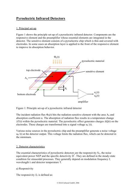
<strong>Pyroelectric</strong> <strong>Infrared</strong> <strong>Detectors</strong>1. Principal set-upFigure 1 shows the principle set-up of a pyroelectric infrared detector. Components are theresponsive element and the preamplifier whose essential elements are integrated in thedetector. The sensitive element consists of a pyroelectric chip which is thin and covered withelectrodes. In some cases an absorption layer is applied to the front of the responsive elementto improve its absorption behavior.Φ S(t)pyroelectric materialtop electrodesensitive elementA Sbottom electroded pu´S(t)u´R(t)Figure 1: Principle set-up of a pyroelectric infrared detectoramplifierThe incident radiation flux Φ S (t) hits the radiation-sensitive element with the area A S andabsorption coefficient α. The absorption of radiation flux results in a temperature change∆T(t) within the pyroelectric material. The pyroelectric effect generates charges ∆Q(t) on theelectrodes. These charges are transformed into a signal voltage u S´(t).Various noise sources in the pyroelectric chip and the preamplifier generate a noise voltageu R´(t) at the detector output. This voltage limits the radiation flux, which can be detected inthe minimum.2. Detector characteristicsThe essential characteristics of pyroelectric detectors are the responsivity S V , the noiseequivalent power NEP and the specific detectivity D * . They are defined in the steady-statecondition for sinusoidal processes. They generally depend on modulation frequency f,wavelength λ and detector temperature T.a) ResponsivityThe responsivity S V is defined as:© <strong>DIAS</strong> <strong>Infrared</strong> GmbH, 2006
SVu~′S= ~ΦS[V/W] (1)where:Φ ~Srms value of the sinusoidally modulated radiation fluxu ~ ′ rms value of the sinusoidal signal voltage at the detector output.Sb) Noise equivalent powerThe noise equivalent power NEP characterises the signal-to-noise ratio of the detector:NEP =u~′RSV[W] (2)where:u ~ ′Rrms value of the noise voltage at the detector output.The combination of the equations (1) and (2) shows that the noise equivalent power representsthe minimum detectable power of the detector, and is given by a ratio of 1 between signalvoltage and noise voltage ( u ~ / u~′ = 1).′S Rc) Specific detectivityThe specific detectivity characterises also the signal-to-noise ratio:D∗=ASBNEP=ASS Vu~ [cmHz 1/2 /W] (3)′Rnwhere:u~ ′ = u~′ B[V/Hz 1/2 ] (4)Rn R/u ~ ′Rneffective value of the noise voltage at the preamplifier outputnormalized on a bandwidth B = 1 Hz.The definition of the specific detectivity allows a simple comparison between the D* value ofthe real sensor and the theoretical D* limit. This limit depends only on nature constants(Boltzmann constant k, Stefan-Boltzmann constant σ) and the temperature T:D∗max= / 161 kσT5(5)For a temperature of 300 K this value amounts to:∗Dmax= 1,8 . 10 10 cmHz 1/2 /W .© <strong>DIAS</strong> <strong>Infrared</strong> GmbH, 2006
3. <strong>Pyroelectric</strong> materialThe pyroelectric material takes a fundamentally position as the real transducer element in thepyroelectric radiation detector. Of 32 existing crystal classes crystals with the point groupbalance 1, m, 2, mm2, 3, 3 m, 4, 4 mm, 6 and 6 mm have a so-called spontaneous polarizationwhich makes the appearance of the pyroelectric effect possible. Crystals of these crystalclasses are called pyroelectric materials. Pyroelctric materials at which the spontaneouspolarization can appear only in one single direction in the crystal (uniaxial pyroelectricmaterials) are technically meaningful. The crystal classes 2, mm2, 3, 3 m, 4, 4 mm, 6 and 6mm, are included. The direction of the spontaneous polarization and the polar axis of thecrystal are the same.For use in pyroelectric radiation detectors the following material characteristics of thepyroelectric material are of importance:pε rtanδc P´pyroelectric coefficientdielectric constantdielectric lossvolume-specific heat capacityFor high values of responsivity S V and specific detectivity D* a big pyroelectric coefficient pand small values of dielectric constant ε r , dielectric loss tan δ and volume-specific heatcapacity c P´ are required.For many years the pyroelectric material lithium tantalate (LiTaO 3 ) has proved itself at use inpyroelectric detectors. It fulfils not only the demands on material characteristic quantities justmentioned but also stands out due to an excellent temperature stability and very goodreproducibility of the detector performance.Typical material properties of LiTaO 3 at room temperature are:p = 1,8 . 10 -8 Ccm -2 K -1ε r = 43tanδ = 0,001c P´ = 3,2 Jcm -3 K -14. Equivalent electric circuits of the responsive element and preamplifierThe absorption of the radiant flux Φ S causes a temperature change ∆T in the pyroelectricmaterial. This temperature change ∆T generally depends on the place in the pyroelectricmaterial. This local dependence can be often neglected in good approximation. The thermalbehavior of the responsive element can be represented in these cases by a simple analogouselectrical substitute circuit diagram (figure 2) with heat capacityH = c′d A(6)PPPSwhere: d P thickness of the responsive elementand thermal conductance G between the sensitive element and his surroundings.© <strong>DIAS</strong> <strong>Infrared</strong> GmbH, 2006
Because of the statistical behaviour of the heat exchange between responsive element andsurrounding a so-called temperature noise is produced. Therefore in figure 2 an additionalnoise source is included, with:~ p = 2RnT4kTG(7)α Φ p 1S RTj . ω . H P1GFigure 2: Analogous electric circuit of the responsive element at simplified thermal conditionsThe temperature variation ∆T leads to a pyroelectric current which flows at short circuit of theelectrodes of the sensitive element. This pyroelectric current arises under consideration of thedefinition of the pyroelectric coefficient and the thermal conditions according to figure 2:iˆ∠PαpΦˆ=c′dPPSTR(8)withTRjωτ+ jωτT= (9)1Tτ = H G(10)T/ω = 2πf(11)The dimensionless function T R is called complex normalized current responsivity. For asensitive element isolated ideally thermally (G = 0) the complex normalized currentresponsivity reaches the value 1. For most sensor constructions and for practically interestingmodulation frequencies f = 1…1000 Hz this value 1 is a good approximation, if the thermaltime constant τ T has corresponding values. If the incident radiation is not modulated (f = 0),no pyroelectric current is produced. A pyroelectric detector is not responsible for a constantradiation. He always needs a temporal modulation of the incident radiant flux e.g. bychopping.Figure 3 shows the electrical circuit of the responsive element. Input quantity is thepyroelectric current after equation (8). Substitute elements are the electrical capacityCε ε Ao r SP= , (12)dP© <strong>DIAS</strong> <strong>Infrared</strong> GmbH, 2006
the frequency dependent resistance( ωCtanδ )rP= 1/P(13)and the so-called tanδ noise source~i = 4kTω tanδ . (14)RnDC PIt describes thermal noise of the element resistance r P .α . p . Φi P =c . P d PST1j ω C PR i RD . .r PFigure 3: Electrical circuit of the responsive elementIn figures 4 and 5 the electrical circuits of two fundamental preamplifier variants(preamplifier in voltage mode or current mode) are represented. Substitute elements are inboth cases the input resistance r eV and input capacitance C eV as well as current noise and~voltage noise i RnVor u ~ RnVof the preamplifier. The thermal noise of the input resistance isdesciped by noise source:~iRnR4kT= . (15)reVIf the preamplifier is operated in voltage mode, gain v V must be taken into account. Thepreamplifier in current mode contains a negative feedback op-amp (gain → ∞) with resistorR GK , his capacity C GK and his thermal noise:~iRnGK4kT= . (16)RGKin1j.ω.C eVr eVi RRi RVu RVuv uV .outFigure 4: Electrical circuit of a preamplifier in voltage mode© <strong>DIAS</strong> <strong>Infrared</strong> GmbH, 2006
i RGKR GK1j.ω.C GKin1j. ω .C eVr eVi RRi RVu RVoutFigure 5: Electrical circuit of a preamplifier in current mode5. ResponsivityAccording to the defining equation (1) the responsivity S V in voltage mode is given by:SVpTRR= αvV(17)c′Pd2P1+ω( CR)with R = r P // r eV (18)C = C P + C eV (19)The electrical time constant is given by:τ = CR . (20)EFor many detectors TR≈ 1, (ωCR) 2 >> 1 and C P >> C eV are valid. Then equation (17)simplifies considerably:SVpαc ′ εV= (21)Prε ωAovSIn this case, responsivity is indirectly proportional to the modulation frequency.The responsivity in current mode is given by:SpTRRGKV= α(22)c′PdP1+( ωC) 2GKRGK© <strong>DIAS</strong> <strong>Infrared</strong> GmbH, 2006
If T ≈ 1 and (ωC GK R GK ) 2 > 1, thenSVp 1= α. (24)c′d ωCPPGK6. Normalized noise voltageDifferent noise sources exist in the pyroelectric detector. They produce a noise voltage at theoutput. The normalised noise voltage shares are:u ~ ′RnTnoise voltage share, caused by the temperature noise sourcep~ of the responsive elementRnTu ~ ′RnDnoise voltage share, caused by the tanδ noise source~i RnDof the responsive element~ noise voltage share, caused by the thermal noiseu ′RnR~i RnRof the input resistor r eV of the preamplifier~ noise voltage share, caused by the current noiseu ′RnI~i RnVof the preamplifier~ noise voltage share, caused by the voltage noiseu ′RnUu ~ RnVof the preamplifieru ~ ′RnGKnoise voltage share, caused by the thermal noise~i RnGKof the resistor R GK of the preamplifier (only in the currentmode of the preamplifier)The whole normalized noise voltage at the preamplifier output arises from square addition ofthe noise voltage shares:Preamplifier in voltage mode:u ~ ′ ′(25)2 ~ 2 ~ 2 ~ 2 ~ 2 ~ 2Rn= u ′RnT+ u ′RnD+ u ′RnR+ u ′RnI+ uRnUPreamplifier in current mode:u ~ ′ ′(26)2 ~ 2 ~ 2 ~ 2 ~ 2 ~ 2 ~ 2Rn= u ′RnT+ u ′RnD+ u ′RnR+ u ′RnI+ u ′RnU+ uRnGKThe equations for the normalised noise voltage shares are arranged in table 1.© <strong>DIAS</strong> <strong>Infrared</strong> GmbH, 2006
Table 1: Effective values of the normalised noise voltage shares at the preamplifier outputXu ~ ′RnXvoltage mode:R = r P // r eV , C = C P + C eVcurrent mode:R`= r P // r eV // R GK , C´= C P + C eV + C GKTS V 2α4 kTG(27)D4kTωCtanδR( ωCR)Pv V21+(28)4kTωCPtanδ1+RGK( ωCR ) 2GKGK(29)R4kTreV1+R( ωCR)2vV(30)4kTreV1+RGK( ωCR ) 2GKGK(31)I~iR( ωCR)RnVv V21+(32)~iRnV1+RGK( ωCR ) 2GKGK(33)Uu ~ RnVvV(34)u~RnVRGKR′11+2+ ( ωC′R′)( ωCR ) 2GKGK(35)GK -4kTRGK1+RGK( ωCR ) 2GKGK(36)7. Specific detectivityThe shares of the specific detectivity caused by the noise voltage shares result from thedefining equation (3) of the specific detectivity as well as the basic equations of theresponsivity (section 5) and normalized noise voltage (section 6):∗DT∗DD∗DR∗DI∗DUshare of the specific detectivity, caused by the temperature noisesource p~RnTof the responsive elementshare of the specific detectivity, caused by the tan δ noise source~of the responsive elementi RnDshare of the specific detectivity, caused by thermal noise~of the input resistor r eV of the preamplifieri RnRshare of the specific detectivity, caused by the current noise~of the preamplifieri RnVshare of the specific detectivity, caused by the voltage noise© <strong>DIAS</strong> <strong>Infrared</strong> GmbH, 2006
∗DGKu ~ RnVof the preamplifiershare of the specific detectivity, caused by the thermal noise~i RnGKof the resistor R GK of the preamplifier (only in the currentmode of the preamplifier)The whole specific detectivity is given by:Preamplifier in voltage mode:⎛⎜⎝1D∗2⎞⎟⎠⎛ 1=⎜⎝ D∗T⎞⎟⎠2⎛ 1+⎜⎝ D∗D⎞⎟⎠2⎛ 1+⎜⎝ D∗R⎞⎟⎠2⎛ 1 ⎞+⎜⎟∗⎝ DI⎠2⎛ 1+ ⎜⎝ D∗U⎞⎟⎠2(37)Preamplifier in current mode:⎛⎜⎝1D∗2⎞⎟⎠⎛ 1=⎜⎝ D∗T⎞⎟⎠2⎛ 1+⎜⎝ D∗D⎞⎟⎠2⎛ 1+⎜⎝ D∗R⎞⎟⎠2⎛ 1 ⎞+⎜⎟∗⎝ DI⎠2⎛ 1+ ⎜⎝ D∗U⎞⎟⎠2⎛ 1+ ⎜∗⎝ DGK⎞⎟⎠2(38)Table 2 contains the equations for the individual shares of the specific detectivity.© <strong>DIAS</strong> <strong>Infrared</strong> GmbH, 2006
Table 2: Shares of the specific detectivityX D X * RemarksTA S2α (39)4kTGDαc′Ppε tanδr14kTεωdoPTR(40)p r Aα T(41)eV SR Rc′P4kTdPp Aα ~ T(42)SI Rc′PiRnVdPUpαc′P1+R( ωCR)2u~ARnVSdPTR(43)voltage mode:R = r P // r eVC = C P + C eVp R′′ 1+ωSα TRcPu~(44)2RnVdPpαc′εPrε u~o( C′R′)RnV1ωASTAR(45)current mode:R`= r P // r eV // R GKC´= C P + C eV + C GKvoltage mode:(ωCR) 2 >> 1, C P >> C eVcurrent mode:(ωC´R´) 2 >> 1, C P >> C eV + C GKp R AGK SGK α TR(46) only in current modec′4kTdPP© <strong>DIAS</strong> <strong>Infrared</strong> GmbH, 2006
8. ExamplesFor the following detector layouts, frequency dependence of responsivity, normalized noisevoltage and specific detectivity are represented in the figures 6 to 11.Detector layout voltage mode current modeResponsive element:<strong>Pyroelectric</strong> material LiTaO 3 LiTaO 3Responsive area A S 2 x 2 mm 2 2 x 2 mm 2Thickness of the element d P 5 µm 5 µmAbsorption coefficient α 0,7 0,7Normalised current responsivity T R 1 1Preamplifier:Input resistance r eV 10 11 Ω 10 11 ΩInput capacity C eV 2 pF 2 pFGain v V 1 -Resistor R GK - 10 10 ΩCapacity C GK - 0,2 pF~Current noise i RnV (10 Hz) 5 . 10 -16 A/Hz 1/2 5 . 10 -16 A/Hz 1/2Voltage noise u ~ RnV(1 kHz) 6 nV/Hz 1/2 6 nV/Hz 1/21E+41E+61E+31E+5S Vin V/W1E+2S Vin V/W1E+41E+11E+31E+01 10 100 10001E+21 10 100 1000f in Hzf in HzFigure 6: Frequency dependence of theFigure 7: Frequency dependence of theresponsivity at voltage mode responsivity at current mode1E+31E+5~' u Rn~' u Rnin nV/Hz 1/21E+21E+1u~'RnR~' u Rnu~'RnI~' u RnD~' u RnU~' u Rnin nV/Hz 1/21E+41E+3u~'RnGK~' u RnRu~'RnUu~'RnI~' u RnD1E+01 10 100 1000f in Hz1E+21 10 100 1000f in HzFigure 8: Frequency dependence of theFigure 9: Frequency dependence of thenormalized noise voltage at normalized noise voltage atvoltage mode current mode© <strong>DIAS</strong> <strong>Infrared</strong> GmbH, 2006
1E+111E+111E+101E+10D* in cm . Hz 1/2 /W1E+91E+8D* RD* ID* DD*D* UD* in cm . Hz 1/2 /W1E+91E+8D* RD* I D* GKD* DD*D* U1E+71 10 100 1000f in Hz1E+71 10 100 1000f in HzFigure 10: Frequency dependence of the Figure 11: Frequency dependence of thespecific detectivity at voltage specific detectivity at currentmode mode© <strong>DIAS</strong> <strong>Infrared</strong> GmbH, 2006