ST3617 - Sunrom Technologies
ST3617 - Sunrom Technologies
ST3617 - Sunrom Technologies

You also want an ePaper? Increase the reach of your titles
YUMPU automatically turns print PDFs into web optimized ePapers that Google loves.
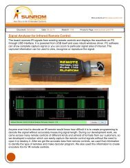
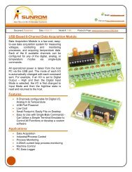
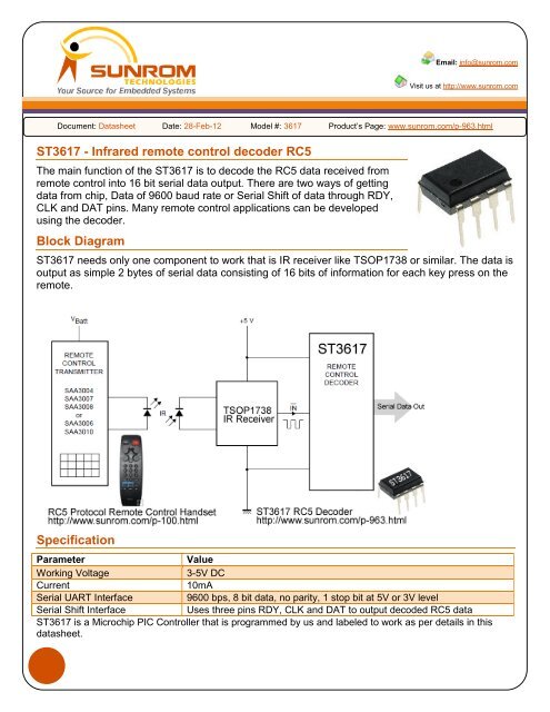
Email: info@sunrom.comVisit us at http://www.sunrom.comDocument: Datasheet Date: 28-Feb-12 Model #: 3617 Product’s Page: www.sunrom.com/p-963.html<strong>ST3617</strong> - Infrared remote control decoder RC5The main function of the <strong>ST3617</strong> is to decode the RC5 data received fromremote control into 16 bit serial data output. There are two ways of gettingdata from chip, Data of 9600 baud rate or Serial Shift of data through RDY,CLK and DAT pins. Many remote control applications can be developedusing the decoder.Block Diagram<strong>ST3617</strong> needs only one component to work that is IR receiver like TSOP1738 or similar. The data isoutput as simple 2 bytes of serial data consisting of 16 bits of information for each key press on theremote.SpecificationParameterValueWorking Voltage3-5V DCCurrent10mASerial UART Interface9600 bps, 8 bit data, no parity, 1 stop bit at 5V or 3V levelSerial Shift InterfaceUses three pins RDY, CLK and DAT to output decoded RC5 data<strong>ST3617</strong> is a Microchip PIC Controller that is programmed by us and labeled to work as per details in thisdatasheet.
Pin Details1-VDD2-IR3-TXD4-N/C<strong>ST3617</strong>8-GND7-DAT6-CLK5-RDYPin# Pin Name Type Notes1 VDD Supply 3 to 5V DC regulated power supply input2 IR Input Connect IR receiver output to this pin3 TXD Output Outputs serial UART data at 9600 bps at TTL level4 N/C Not Used Not Connected, This pin is not used and should be left unconnected5 RDY Output Ready Signal Output of Serial Shift Interface6 CLK Input Clock Input of Serial Shift Interface7 DAT Output Data Output of Serial Shift Interface8 GND Ground Power Supply GroundData Interface for <strong>ST3617</strong> RC5 DecoderThere are two ways you can get the output from <strong>ST3617</strong>. For each output the data is two bytes longcontaining total 16 bits RC5 data.Two types of Interface for reading RC5 data from <strong>ST3617</strong>C1100nFU3TSOP1738GNDVCC32IR1+5V1234U2<strong>ST3617</strong>VDDIRTXDN/CGND 87DAT6CLK5RDYInterface #1Serial Shift InterfaceDATCLKRDYInterface #2Serial Data at 9600bpsTXDThere are two type ofInterface to get decodedRC5 data from <strong>ST3617</strong>, Anyone of it can be used inthe application.Interface #1 is SerialShift Interface, whichconsist of three pins. Inthis interface you haveto monitor RDY pin togo low which meansnew RC5 data hasarrived. Then you shiftoutput data using DATand CLK pins. You canuse any I/O of yourapplicationmicrocontroller.Interface #2 is SerialData at 9600 bps isparticular useful whenyou have a dedicatedserial input pin availableon your applicationmicrocontroller to getthe 2 bytes of data. You can also use the serial data to interface to PC using MAX232 levelconvertor for serial port or use USB-TTL chip to get a virtual serial port on PC to which manysoftware like Hyperterminal can be connected. Custom software can also be made to monitor theincoming data.2<strong>Sunrom</strong> <strong>Technologies</strong> Your Source for Embedded Systems Visit us at www.sunrom.com
Philips RC5 ProtocolLet us review the RC5 protocol to understand the RC5decoder IC <strong>ST3617</strong> better. The RC5 code from Philips ispossibly the most used protocol by hobbyists, probablybecause of the wide availability of cheap remote controls.RC5 Protocol Remote Control Handsethttp://www.sunrom.com/p-100.htmlThe protocol is well defined for different device typesensuring compatibility with your whole entertainment system.Features of Protocol• 5 bit address and 6 bit command length• Bi-phase coding (aka Manchester coding)• Carrier frequency of 36kHz or 38kHz• Constant bit time of 1.778ms (64 cycles of 36 kHz), Different timing for 38Khz, Should beadjusted in decoder part by monitoring first two bits.• Manufacturer PhilipsModulationRC5 Modulation The protocol uses bi-phase modulation (or so-called Manchester coding) of a36kHz IR carrier frequency. All bits areof equal length of 1.778ms in thisprotocol, with half of the bit time filledwith a burst of the 36kHz carrier and theother half being idle. A logical zero isrepresented by a burst in the first half ofthe bit time. A logical one is represented by a burst in the second half of the bit time. Thepulse/pause ratio of the 36kHz carrier frequency is 1/3 or 1/4 which reduces power consumption.ProtocolThe drawing below shows a typical pulse train of an RC-5 message. This example transmitscommand $35 to address $05.RC-5 Pulse TrainThe first two pulses are the start pulses, and are both logical "1". Please note that half a bit time iselapsed before the receiver will notice the real start of the message.3<strong>Sunrom</strong> <strong>Technologies</strong> Your Source for Embedded Systems Visit us at www.sunrom.com
The 3rd bit is a toggle bit. This bit is inverted every time a key is released and pressed again. Thisway the receiver can distinguish between a key that remains down, or is pressed repeatedly.The next 5 bits represent the IR device address, which is sent with MSB first. The address isfollowed by a 6 bit command, again sent with MSB first.A message consists of a total of 14 bits, which adds up to a total duration of 25 ms. Sometimes amessage may appear to be shorter because the first half of the start bit S1 remains idle. And if thelast bit of the message is a logic "0" the last half bit of the message is idle too.As long as a key remains down the message will be repeated every 114ms. The toggle bit will retainthe same logical level during all of these repeated messages. It is up to the receiver software tointerpret this auto repeat feature.Output Data formatOutput from <strong>ST3617</strong> is in two bytes, thus making total 16 bits of data, let us see meaning of each bitHigh Byte - FirstBit Position-> 15 14 13 12 11 10 9 8Value 0 0 1 1 T A4 A3 A2Always 0 Always 0 Always 1 Always 1Toggle Bit0 or 1Address Address AddressLow Byte - SecondBit -> 7 6 5 4 3 2 1 0Value A1 A0 D5 D4 D3 D2 D1 D0A4-A0 = RC5 address of remote control, For TV remote this is zero.D5-D0 = RC5 command for each keypress at remote control. For Key 1 its 1, Key 2 = 2 and such,Find a table on last of this datasheet showing key value for each key press.ExampleFor example pressing Key 1 on remote control can output 0x3001 where 0x30 is high byte and 0x01is low byte.If we interpret, in terms of RC5 data we get belowHigh: 0x30 in binary isBit -> 15 14 13 12 11 10 9 8Data-> 0 0 1 1 0 0 0 0Toggle A4 A3 A2Low: 0x01 in binary isBit -> 7 6 5 4 3 2 1 0Data-> 0 0 0 0 0 0 0 1Value A1 A0 D5 D4 D3 D2 D1 D04<strong>Sunrom</strong> <strong>Technologies</strong> Your Source for Embedded Systems Visit us at www.sunrom.com
Note the Toggle is zero in this example, It can also be one, in this case you can get 0x3801 for key1value. If you keep the Key1 pressed, the next output will have toggle value same as zero. If youleave Key1 and then press again, the toggle value will be one. Therefore toggle tells you if user iskeeping the key press or left the key once and pressed again. This is particular useful if you areimplementing Toggle output like Relay ON and OFF logic.The Address bits A0 to A4 are zero since TV remote has zero RC5 address.The Command bits D0 to D5 are 0x01 since User has pressed Key1 and value of key1 is 1.Serial Data Output FormatWhen you see data output from chip in serial at 9600 baud rate, you will get total six bytes output aseach key press in ASCII format so you can view it on screen.Let us see what data output you will get in serial mode. The last two bytes in serial mode are newline characters so that when you see this data in terminal you can see each new data in new line. Ifyou press Key1 on remote, you will get following outputExample Output of Serial in terminal software for Key1:3001Interpreting above result in below tableBYTE COUNT HEX DECIMAL CHARACTER DISPLAYED Details1 0x33 51 ‘3’ RC5 Data High Byte2 0x30 48 ‘0’ RC5 Data High Byte3 0x30 48 ‘0’ RC5 Data Low Byte4 0x31 49 ‘1’ RC5 Data Low Byte5 0x0D 13 ‘\r’ = CR New Line Character6 0x0A 10 ‘\n’ = LF New Line CharacterThe above values in serial data are ASCII characters. You can convert the value to binary to use inyour program by deducting 0x30 from ASCII value. Our sample code given on next page uses thistechnique to convert this ASCII buffer of four digit to single integer of RC5 data variable containing16 bits.5<strong>Sunrom</strong> <strong>Technologies</strong> Your Source for Embedded Systems Visit us at www.sunrom.com
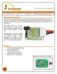
Application example using serial dataWe have used AT89C51’s RXD pin to receive serial data from <strong>ST3617</strong> and we switch on Relay ONor OFF for Key1 pressed on Remote. Key1 when first pressed will turn relay ON and Key1 pressedpressed again will make Relay OFF. Relay used is 5V type. But can be any voltage if you havehigher voltage available on your application. You can use any microcontroller to interface using thisinterface. We have chosen AT89C51 to show since it is more widely used. The sample code wehave given can be adapted to any C compiler or any microcontrollers like AVR or PIC since withminor changes.Source code can be downloaded fromhttp://www.sunrom.com/files/3617-samplecode.zipCode is compiled using keil compilerU6TSOP1738C2+5VC3100nFGNDVCC32IR1CN1PBT3+5VTXD1234U5<strong>ST3617</strong>534VDDIRTXDN/CLS1RELAY12Q1BC5478GND7DAT6CLK+5V5RDY9600 bps serial data+5VD11N4007R21K212223242526272810111213141516172930100nP2.0/A8P2.1/A9P2.2/A10P2.3/A11P2.4/A12P2.5/A13P2.6/A14P2.7/A15P3.0/RXDP3.1/TXDP3.2/INT0P3.3/INT1P3.4/T0P3.5/T1P3.6/WRP3.7/RDPSENALE/PROGXTAL21840VCCXTAL119U4AT89C51P0.0/AD0P0.1/AD1P0.2/AD2P0.3/AD3P0.4/AD4P0.5/AD5P0.6/AD6P0.7/AD7EA/VPPGND2039383736353433321P1.0/T2P1.1/T2EX 23P1.24P1.35P1.4/SS6P1.5/MOSIP1.6/MISO 78P1.7/SCKRST319+5VC510uF 16VR110KY1C833p11.0592C733pIMPORTANT: In serial data mode, the CLK pin#6 has to be connected to +5V to get data from TXDpin as shown above.6<strong>Sunrom</strong> <strong>Technologies</strong> Your Source for Embedded Systems Visit us at www.sunrom.com
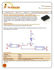
Application example using serial shift dataAdvantage of this technique is it uses three general purpose I/O pins of MCU instead of dedicatedRXD pin. This will make RXD available for other applications .We have used AT89C51’s I/O pin toreceive data from <strong>ST3617</strong> and we switch on Relay ON or OFF for Key1 pressed on Remote. Key1when first pressed will turn relay ON and Key1 pressed pressed again will make Relay OFF. Relayused is 5V type. But can be any voltage if you have higher voltage available on your application.You can use any microcontroller to interface using this interface. We have chosen AT89C51 toshow since it is more widely used. The sample code we have given can be adapted to any Ccompiler or any microcontrollers like AVR or PIC since with minor changes.Source code can be downloaded fromhttp://www.sunrom.com/files/3617-samplecode.zipCode is compiled using keil compilerU9TSOP1738C4+5VC11100nFGNDVCC32IR1CN2PBT3+5V1234U8<strong>ST3617</strong>534VDDIRTXDN/CLS2RELAY12Q2BC547GND 87DATCLK 65RDY+5VDATCLKRDYD21N4007R41K212223242526272810111213141516172930100nP2.0/A8P2.1/A9P2.2/A10P2.3/A11P2.4/A12P2.5/A13P2.6/A14P2.7/A15P3.0/RXDP3.1/TXDP3.2/INT0P3.3/INT1P3.4/T0P3.5/T1P3.6/WRP3.7/RDPSENALE/PROG18XTAL2VCC 4019XTAL1U7AT89C51P0.0/AD0P0.1/AD1P0.2/AD2P0.3/AD3P0.4/AD4P0.5/AD5P0.6/AD6P0.7/AD7EA/VPPGND2039383736353433321P1.0/T2P1.1/T2EX 23P1.24P1.35P1.4/SS6P1.5/MOSIP1.6/MISO 78P1.7/SCKRST319+5VC610uF 16VR310KY2C933p11.0592C1033p7<strong>Sunrom</strong> <strong>Technologies</strong> Your Source for Embedded Systems Visit us at www.sunrom.com
RC5 address and command TableCommonly used Address and Command data are as per table belowRC5 ADDRESS of EQUIPMENTRemote Control0 TV SET 11 TV SET 22 VIDEOTEXT3 EXPANSION FOR TV 1 AND 24 LASER VIDEO PLAYER5 VIDEO RECORDER 1 (VCR 1)6 VIDEO RECORDER 2 (VCR 2)7 RESERVED8 SAT 19 EXPANSION FOR VCR 1 OR 210 SAT 211 RESERVED12 CD VIDEO13 RESERVED14 CD PHOTO15 RESERVED16 AUDIO PREAMPLIFIER 117 RECEIVER / TUNER18 TAPE / CASSETE RECORDER19 AUDIO PREAMPLIFIER 220 CD21 AUDIO RACK22 AUDIO SAT RECEIVER23 DCC RECORDER24 RESERVED25 RESERVED26 WRITABLE CD26-31 RESERVEDKeypress in Remote Control are RC5 commandsRC5 COMMAND DESCRIPTION of FUNCTION(in decimal)0-9 NUMERIC KEYS 0 - 912 STANDBY13 MUTE14 PRESETS16 VOLUME UP17 VOLUME DOWN18 BRIGHTNESS +19 BRIGHTNESS -20 COLOR SATURATION +21 COLOR SATURATION -22 BASS UP23 BASS DOWN24 TREBLE +25 TREBLE -26 BALANCE RIGHT27 BALANCE LEFT48 PAUSE50 FAST REVERSE52 FAST FORWARD-53 PLAY54 STOP55 RECORD63 SYSTEM SELECT8<strong>Sunrom</strong> <strong>Technologies</strong> Your Source for Embedded Systems Visit us at www.sunrom.com
Dimensions DIP Package8-Lead Plastic Dual In-line (P) – 300 mil (PDIP)9<strong>Sunrom</strong> <strong>Technologies</strong> Your Source for Embedded Systems Visit us at www.sunrom.com
Related ProductsRC5 Remote Controlhttp://www.sunrom.com/rf-wireless/ir-remote-control/rc5-protocol-remote-control-handsetRemote control for transmitting RC5 dataSAA3010http://www.sunrom.com/p-998.htmlRC5 transmitter ICUSB to Serial TTLhttp://www.sunrom.com/usb-to-serial-rs232/usb-to-serial-ttl-boardAccess <strong>ST3617</strong> data to PC using this board, It installs virtual COM port on PC towhich any terminal software can connect.MAX232 Boardhttp://www.sunrom.com/usb-to-serial-rs232/max232-boardConvert TTL(3-5V) level data from <strong>ST3617</strong> to RS232 level(+/- 12V) suitable forconnected to serial port of PC.10<strong>Sunrom</strong> <strong>Technologies</strong> Your Source for Embedded Systems Visit us at www.sunrom.com