

pic24fj128ga010 family - Microchip
pic24fj128ga010 family - Microchip
pic24fj128ga010 family - Microchip

Create successful ePaper yourself
Turn your PDF publications into a flip-book with our unique Google optimized e-Paper software.
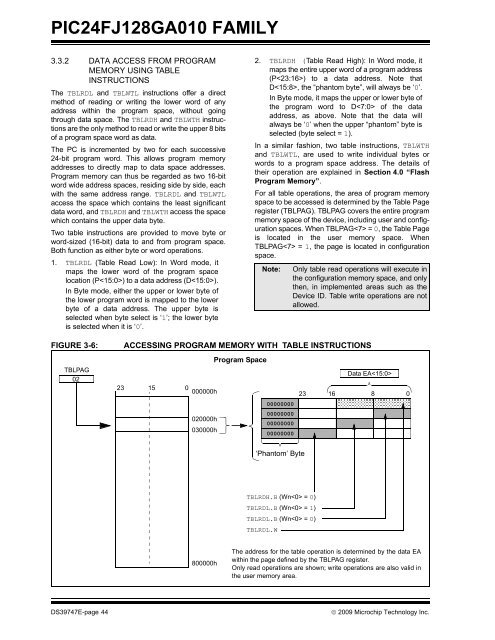
PIC24FJ128GA010 FAMILY3.3.2 DATA ACCESS FROM PROGRAMMEMORY USING TABLEINSTRUCTIONSThe TBLRDL and TBLWTL instructions offer a directmethod of reading or writing the lower word of anyaddress within the program space, without goingthrough data space. The TBLRDH and TBLWTH instructionsare the only method to read or write the upper 8 bitsof a program space word as data.The PC is incremented by two for each successive24-bit program word. This allows program memoryaddresses to directly map to data space addresses.Program memory can thus be regarded as two 16-bitword wide address spaces, residing side by side, eachwith the same address range. TBLRDL and TBLWTLaccess the space which contains the least significantdata word, and TBLRDH and TBLWTH access the spacewhich contains the upper data byte.Two table instructions are provided to move byte orword-sized (16-bit) data to and from program space.Both function as either byte or word operations.1. TBLRDL (Table Read Low): In Word mode, itmaps the lower word of the program spacelocation (P) to a data address (D).In Byte mode, either the upper or lower byte ofthe lower program word is mapped to the lowerbyte of a data address. The upper byte isselected when byte select is ‘1’; the lower byteis selected when it is ‘0’.2. TBLRDH (Table Read High): In Word mode, itmaps the entire upper word of a program address(P) to a data address. Note thatD, the “phantom byte”, will always be ‘0’.In Byte mode, it maps the upper or lower byte ofthe program word to D of the dataaddress, as above. Note that the data willalways be ‘0’ when the upper “phantom” byte isselected (byte select = 1).In a similar fashion, two table instructions, TBLWTHand TBLWTL, are used to write individual bytes orwords to a program space address. The details oftheir operation are explained in Section 4.0 “FlashProgram Memory”.For all table operations, the area of program memoryspace to be accessed is determined by the Table Pageregister (TBLPAG). TBLPAG covers the entire programmemory space of the device, including user and configurationspaces. When TBLPAG = 0, the Table Pageis located in the user memory space. WhenTBLPAG = 1, the page is located in configurationspace.Note:Only table read operations will execute inthe configuration memory space, and onlythen, in implemented areas such as theDevice ID. Table write operations are notallowed.FIGURE 3-6:TBLPAG02ACCESSING PROGRAM MEMORY WITH TABLE INSTRUCTIONSProgram SpaceData EA23 15 0000000h23 1680000000000000000020000h00000000030000h000000000‘Phantom’ ByteTBLRDH.B (Wn = 0)TBLRDL.B (Wn = 1)TBLRDL.B (Wn = 0)TBLRDL.W800000hThe address for the table operation is determined by the data EAwithin the page defined by the TBLPAG register.Only read operations are shown; write operations are also valid inthe user memory area.DS39747E-page 44© 2009 <strong>Microchip</strong> Technology Inc.


