The dualband feedhorn for 10 and 24 GHz by AA6IW and ... - W1GHZ
The dualband feedhorn for 10 and 24 GHz by AA6IW and ... - W1GHZ
The dualband feedhorn for 10 and 24 GHz by AA6IW and ... - W1GHZ

You also want an ePaper? Increase the reach of your titles
YUMPU automatically turns print PDFs into web optimized ePapers that Google loves.
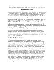
A Filter <strong>for</strong> the Dual-b<strong>and</strong> <strong>10</strong> & <strong>24</strong> <strong>GHz</strong> Feedhorn <strong>for</strong> Offset DishesPaul Wade <strong>W1GHZ</strong> ©2006w1ghz@arrl.net<strong>The</strong> dual-b<strong>and</strong> <strong>feedhorn</strong> <strong>for</strong> <strong>10</strong> <strong>and</strong> <strong>24</strong> <strong>GHz</strong> <strong>by</strong> AD6FP <strong>and</strong> <strong>AA6IW</strong> 1 has proven verypopular – if all of them were on the air, <strong>24</strong> <strong>GHz</strong> would be a very active b<strong>and</strong>. <strong>The</strong> oneshortcoming of this <strong>feedhorn</strong> is the isolation between ports. While it is excellent at <strong>10</strong><strong>GHz</strong>, since the waveguide of the <strong>24</strong> <strong>GHz</strong> port is well beyond cutoff, it is only about 9 dBat <strong>24</strong> <strong>GHz</strong>. With a number of medium-power <strong>24</strong> <strong>GHz</strong> amplifiers in use, there is a dangerof excessive power reaching the <strong>10</strong> <strong>GHz</strong> receiver.In my own setup, I have used a surplus 8-12 <strong>GHz</strong> b<strong>and</strong>pass filter on the <strong>10</strong> <strong>GHz</strong> port,which provides adequate rejection of the <strong>24</strong> <strong>GHz</strong> power, protecting the <strong>10</strong> <strong>GHz</strong> front end.<strong>The</strong>se filters are not common, so a reproducible solution was needed.This is not a hard problem – all that is needed is a low-pass filter to separate two widelyseparated frequencies, passing <strong>10</strong>.368 <strong>GHz</strong> <strong>and</strong> rejecting <strong>24</strong> <strong>GHz</strong>. <strong>The</strong> cutoff frequencycould be anywhere in between. It does not need to be a very good filter, since we don’tcare about other frequencies, just two narrow b<strong>and</strong>s.<strong>The</strong> first thought was that a simple stub, resonant at <strong>24</strong> <strong>GHz</strong>, would probably provideadequate rejection. However, it would also cause a mismatch at <strong>10</strong> <strong>GHz</strong>. An oldmicrowave trick is that two identical mismatches, separated <strong>by</strong> a quarter-wavelength, will
cancel. So the mismatch could be removed <strong>by</strong> a second stub, ¼ λ away at <strong>10</strong>.368 <strong>GHz</strong>.A quick simulation using the free Student Version of Ansoft Designer software 2 showedat least 30 dB rejection at <strong>24</strong> <strong>GHz</strong>, but the rejection notch <strong>and</strong> the <strong>10</strong> <strong>GHz</strong> passb<strong>and</strong> wereboth pretty narrow, so dimensions would be pretty critical. Finally, I couldn’t figure outa way to make it without a bit of machining.Mechanically, it would be better if the filter were a coaxial structure, in line with theSMA connector. One <strong>for</strong>m of microwave low-pass filter uses alternating sections ofhigh- <strong>and</strong> low-impedance transmission line, or thin <strong>and</strong> fat coax. Other versions replacethe low-impedance sections <strong>by</strong> capacitors or stubs. I played around with variations onthis theme <strong>and</strong> found a combination that might work – thin disks, spaced about a ¼ λ.<strong>The</strong> disks might be considered capacitors, or as stubs of radial transmission line, but thestep from thin center conductor to disk is also a capacitor. Properly accounting <strong>for</strong> all thestray capacitances took some fiddling of dimensions using Ansoft HFSS 2 , a 3Delectromagnetic simulator, to come up with a good combination of <strong>24</strong> <strong>GHz</strong> rejection withlow loss <strong>and</strong> VSWR around <strong>10</strong> <strong>GHz</strong>. <strong>The</strong> calculated per<strong>for</strong>mance is shown in Figure 1shows about 23 dB rejection.Figure 1
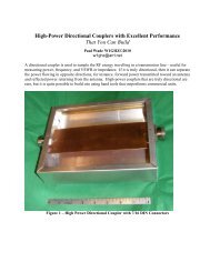
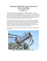
Figure 2<strong>The</strong> dimensions of the filter are sketched in Figure 2. Construction is intended to besimple: take a long-pin SMA connector, cut off the Teflon insulator square at the pointwhere the first disc sits, slide on the two disks, space carefully, <strong>and</strong> solder. Replace therest of the Teflon, then trim it so that only the bare probe protrudes into the horn.Figure 3<strong>The</strong> connector assembly sits in a block shown in Figure 3. Using st<strong>and</strong>ard long-pin SMAconnectors <strong>and</strong> the block thickness shown, the probe length is exactly right <strong>for</strong> the horn.
<strong>The</strong> completed filter is shown in the photos ready <strong>for</strong> assembly below <strong>and</strong> installed on thenew one-piece version of the dual-mode <strong>feedhorn</strong> above.<strong>The</strong> test results were good: <strong>24</strong> <strong>GHz</strong> rejection on two prototypes was 31 <strong>and</strong> 32 dB. Sincewe predicted 23 dB from the filter <strong>and</strong> measured 9 dB <strong>for</strong> the <strong>feedhorn</strong> alone, this meetsour expectations. VSWR at <strong>10</strong> <strong>GHz</strong> was slightly better than without the filter, <strong>and</strong>unaffected at <strong>24</strong> <strong>GHz</strong>.Loss is more difficult to measure, since only one end has a connector. Two <strong>feedhorn</strong>swithout filters were butted together, then one replaced <strong>by</strong> a <strong>feedhorn</strong> with a filter; thedifference in loss was small. Another check was to measure the return loss with a metalplate shorting the horn aperture – also small. <strong>The</strong>se are only rough measurements, butthe loss of the filter is probably less than ½ dB.This filter per<strong>for</strong>ms as designed, should be easy to reproduce, <strong>and</strong> provides adequateprotection <strong>for</strong> a <strong>10</strong> <strong>GHz</strong> LNA from medium-power <strong>24</strong> <strong>GHz</strong> amplifiers, up to at least the3-watt level. We hope to have kits available in the near future.References:1. Gary Lauterbach, AD6FP, <strong>and</strong> Lars Karlsson, <strong>AA6IW</strong>, “Dual-B<strong>and</strong> <strong>10</strong>/<strong>24</strong> <strong>GHz</strong>Feedhorns <strong>for</strong> Shallow Dishes,” Proceedings of Microwave Update 2001, ARRL,2001, pp. 181-190.2. www.ansoft.com