Extech EX420/EX430 Multimeter Manual PDF - Instrumart
Extech EX420/EX430 Multimeter Manual PDF - Instrumart
Extech EX420/EX430 Multimeter Manual PDF - Instrumart
- No tags were found...

Create successful ePaper yourself
Turn your PDF publications into a flip-book with our unique Google optimized e-Paper software.
C ONCEPTAS IEKMANN, J ANELL UND P ARTNERWIRTSCHAFTSPRÜFER . STEUERBERATER . RECHTSANWALTSiekmann, Janell und Partner . Postfach 20 61 . 32010 HerfordINDEPENDENT MEMBER OFMORISONINTERNATIONALHellerweg 28, 32052 HerfordDiplom-FinanzwirtReiner SiekmannSteuerberaterDiplom-KaufmannWilhelm UpheberWirtschaftsprüfer SteuerberaterDiplom-KaufmannWinfried ArbeiterWirtschaftsprüfer SteuerberaterMandanten-Rundschreiben August 2006Gesetzgebung: Anhebung Umsatzsteuersatz, Änderungen bei 400 €-Jobs,Entfernungspauschale, Zuschlag zur Einkommensteuer • Anforderungen anumsatzsteuerliche Rechnungen • Rechtsprechung zum häuslichen ArbeitszimmerSehr geehrte Damen und Herren,nach der gesetzgeberischen Sommerpause sollen in diesem Herbst nochverschiedene weitere Gesetze verabschiedet werden. Hierzu gehöreninsbesondere das Unternehmensnachfolgeerleichterungsgesetz sowie dasGesetz über steuerliche Begleitmaßnahmen zur Einführung der EuropäischenGesellschaft. Wir hatten hierüber bereits in unseren vorhergehendenMandantenrundschreiben berichtet. Mit unserem heutigen Rundschreibenmöchten wir noch einmal die wesentlichen Punkte des bereits verabschiedetenHaushaltsbegleitgesetzes 2006, des Steueränderungsgesetzes 2007 sowie desMittelstandsentlastungsgesetzes zusammenfassen. Darüber hinaus werden wirauf die Eckpunkte der vom Bundeskabinett beschlossenen Unternehmenssteuerreform2008 eingehen. Zurzeit bestehen hier allerdings noch erheblicheUnsicherheiten, da verschiedene bekannt gewordene Detailfragen in der Koalitionumstritten sind.Da die Erhöhung des allgemeinen Umsatzsteuersatzes zum 1.1.2007 von 16 %auf 19 % immer näher rückt, möchten wir Ihre besondere Aufmerksamkeit auf diehiermit verbundenen vielfältigen Probleme richten. So ist bei steuerpflichtigenDauerschuldverhältnissen, wie z. B. Miet- und Leasingverträgen, eine Umstellungnotwendig, um die dann erhöhte Steuer auch zukünftig als Vorsteuer geltendmachen zu können. Daneben ergeben sich eine Vielzahl von Abgrenzungsfragen,auf die ein (erstaunlich frühzeitig veröffentlichtes) aktuelles BMF-Schreiben ersteAntworten gibt.Weitere wichtige Themen aus Rechtsprechung, Verwaltung und Gesetzgebungfinden Sie in gewohnter Weise zu den einzelnen Rubriken diesesRundschreibens.Bernhard KauneRechtsanwalt SteuerberaterFachanwalt für SteuerrechtDiplom-KaufmannThomas LilienthalWirtschaftsprüfer SteuerberaterPostfach 20 61, 32010 HerfordTelefon: 0 52 21 / 98 31-0Telefax: 0 52 21 / 98 31 40E-Mail: info@SJP-Steuerberater.deInternet: www.SJP-Steuerberater.deAmtsgericht Essen PR 1206Johannisstr. 45, 32052 HerfordDiplom-KaufmannSiegbert HuntebrinkerWirtschaftsprüfer SteuerberaterDiplom-KaufmannPeter SturmWirtschaftsprüfer SteuerberaterDiplom-IngenieurHans-Burkhard GranzowSteuerberaterPostfach 13 05, 32003 HerfordTelefon: 0 52 21 / 18 07 01Telefax: 0 52 21 / 18 07 89E-Mail: info@stbherford.deInternet: www.stbherford.deverbunden mit:MORISON AGWirtschaftsprüfungsgesellschaftHellerweg 28, 32052 HerfordDr. Woelke Treuhand-Gesellschaft mbHWirtschaftsprüfungsgesellschaftSteuerberatungsgesellschaftHellerweg 28, 32052 Herford1
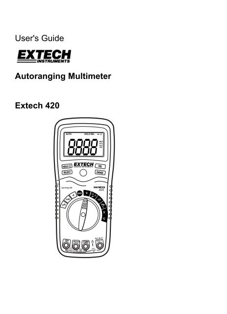
IntroductionCongratulations on your purchase of the <strong>Extech</strong> 420 (part number<strong>EX420</strong>) Autoranging <strong>Multimeter</strong>. This meter measures AC/DCVoltage, AC/DC Current, Resistance, Capacitance, Frequency,Duty Cycle, Diode Test, and Continuity plus ThermocoupleTemperature. Proper use and care of this meter will provide manyyears of reliable service.SafetyWARNINGCAUTIONMAX600VThis symbol adjacent to another symbol,terminal or operating device indicates that theoperator must refer to an explanation in theOperating Instructions to avoid personal injuryor damage to the meter.This WARNING symbol indicates a potentiallyhazardous situation, which if not avoided,could result in death or serious injury.This CAUTION symbol indicates a potentiallyhazardous situation, which if not avoided, mayresult damage to the product.This symbol advises the user that theterminal(s) so marked must not be connectedto a circuit point at which the voltage withrespect to earth ground exceeds (in this case)600 VAC or VDC.This symbol adjacent to one or more terminalsidentifies them as being associated withranges that may, in normal use, be subjectedto particularly hazardous voltages. Formaximum safety, the meter and its test leadsshould not be handled when these terminalsare energized.This symbol indicates that a device isprotected throughout by double insulation orreinforced insulation.2V1.1 9/04
SpecificationsFunction Range Resolution AccuracyDCVoltageACVoltageDCCurrentACCurrent400mV 0.1mV ±(0.3% reading + 2 digits)4V 0.001V40V 0.01V400V 0.1V±(0.5% reading + 2 digits)1000V 1V ±(0.8% reading + 3 digits)400mV 0.1mV ±(1.5% reading+ 15 digits)4V 0.001V40V 0.01V400V 0.1V50 to 400Hz 400Hz to 1kHz±(1.5% reading+ 6 digits)750V 1V ±(1.8% reading+ 6 digits)400µA 0.1µA4000µA 1µA40mA400mA0.01mA0.1mA4A 0.001A20A 0.01A400µA 0.1µA4000µA 1µA40mA0.01mA400mA 0.1mA4A 0.001A20A 0.01A±(2.5% reading+ 15digits)±(2.5% reading+ 8 digits)±(3% reading +8 digits)±(1.5% reading + 3 digits)±(2.5% reading + 5 digits)50 to 400Hz 400Hz to 1KHz±(1.8% reading+ 8 digits)±(3.0% reading+ 8 digits)±(3.0% reading+ 7 digits)±(3.5% reading+ 10 digits)NOTE: Accuracy is stated at 65 o F to 83 o F (18 o C to 28 o C) and lessthan 75% RH.5V1.1 9/04
Function Range Resolution AccuracyResistanceCapacitanceFrequencyDuty Cycle400Ω 0.1Ω ±(0.8% reading + 4 digits)4kΩ 0.001kΩ ±(0.8% reading + 2 digits)40kΩ400kΩ4MΩ0.01kΩ0.1kΩ0.001MΩ±(1.0% reading + 2 digits)40MΩ 0.01MΩ ±(3.0% reading + 5 digits)40nF 0.01nF ±(5.0% reading + 7 digits)400nF 0.1nF ±(3.0% reading + 5 digits)4µF 0.001µF40µF 0.01µF±(3.5% reading + 5 digits)100µF 0.1µF ±(5.0% reading + 5 digits)5.000Hz50.00Hz500.0Hz0.001Hz0.01Hz0.1Hz5.000kHz 0.001kHz50.00kHz 0.01kHz500.0kHz 0.1kHz5.000MHz 0.001MHz10.00MHz 0.01MHz±(1.5% reading + 5 digits)±(1.2% reading + 2 digits)±(1.5% reading + 4 digits)Sensitivity: 0.8V rms min. @ 20% to 80% duty cycle and 100kHz.0.1 to 99.9% 0.1% ±(1.2% reading + 2 digits)Pulse width: 100µs - 100ms, Frequency: 5Hz to 150kHzTemp -4 to 1382°F 1°F(type-K) -20 to 750°C 1°C±(3.0% reading + 3 digits)(probe accuracy not included)NOTE: Accuracy specifications consist of two elements:• (% reading) – This is the accuracy of the measurement circuit.• (+ digits) – This is the accuracy of the analog to digitalconverter.6V1.1 9/04
Diode TestTest current of 0.3mA maximum,open circuit voltage 1.5V DC typicalContinuity CheckAudible signal will sound if theresistance is less than 150Ω(approx.), test current 7.5MΩ (VDC & VAC)AC ResponseAverage respondingACV Bandwidth50Hz to 1kHzDisplay4000 count backlit liquid crystalOverrange indication “OL” is displayedAuto Power Off15 minutes (approximately)PolarityAutomatic (no indication forpositive); Minus (-) sign for negativeMeasurement Rate 2 times per second, nominalLow Battery Indication “ ” is displayed if battery voltagedrops below operating voltageBatteryOne 9 volt (NEDA 1604) batteryFusesmA, µA ranges; 0.5A/250V fast blowA range; 20A/250V ceramic fastblowOperating Temperature 41ºF to 104ºF (5ºC to 40ºC)Storage Temperature -4 o F to 140 o F (-20 o C to 60 o C)Operating Humidity Max 80% up to 87ºF (31ºC)decreasing linearly to 50% at104ºF(40ºC)Storage Humidity
Operating InstructionsWARNING: Risk of electrocution. High-voltage circuits, both ACand DC, are very dangerous and should be measured with greatcare.1. ALWAYS turn the function switch to the OFF position when themeter is not in use.2. If “OL” appears in the display during a measurement, the valueexceeds the range you have selected. Change to a higher range.NOTE: On some low AC and DC voltage ranges, with the testleads not connected to a device, the display may show arandom, changing reading. This is normal and is caused by thehigh-input sensitivity. The reading will stabilize and give a propermeasurement when connected to a circuit.DC VOLTAGE MEASUREMENTSCAUTION: Do not measure DC voltages if a motor on thecircuit is being switched ON or OFF. Large voltage surges mayoccur that can damage the meter.1. Set the function switch to the greenV position.2. Press the SELECT button to indicate“DC” on the display.3. Insert the black test lead bananaplug into the negative COM jack.Insert the red test lead banana pluginto the positive V jack.4. Touch the black test probe tip to thenegative side of the circuit.Touch the red test probe tip to thepositive side of the circuit.5. Read the voltage in the display.8V1.1 9/04
AC VOLTAGE MEASUREMENTSWARNING: Risk of Electrocution. The probe tips may not belong enough to contact the live parts inside some 240V outletsfor appliances because the contacts are recessed deep in theoutlets. As a result, the reading may show 0 volts when theoutlet actually has voltage on it. Make sure the probe tips aretouching the metal contacts inside the outlet before assumingthat no voltage is present.CAUTION: Do not measure AC voltages if a motor on thecircuit is being switched ON or OFF. Large voltage surges mayoccur that can damage the meter.1. Set the function switch to the greenV position.2. Press the SELECT button to indicate“AC” on the display.3. Insert the black test lead bananaplug into the negative COM jack.Insert red test lead banana plug intothe positive V jack.4. Touch the black test probe tip to theneutral side of the circuit.Touch the red test probe tip to the“hot” side of the circuit.5. Read the voltage in the display.9V1.1 9/04
DC CURRENT MEASUREMENTSCAUTION: Do not make current measurements on the 20Ascale for longer than 30 seconds. Exceeding 30 seconds maycause damage to the meter and/or the test leads.1. Insert the black test leadbanana plug into the negativeCOM jack.2. For current measurements upto 4000µA DC, set thefunction switch to the yellowµA position and insert the redtest lead banana plug into theµA/mA jack3. For current measurements upto 400mA DC, set the functionswitch to the yellow mAposition and insert the red testlead banana plug into theµA/mA jack.4. For current measurements upto 20A DC, set the functionswitch to the yellow 20A rangeand insert the red test leadbanana plug into the 20A jack.5. Press the SELECT button to indicate “DC” on the display.6. Remove power from the circuit under test, then open up thecircuit at the point where you wish to measure current.7. Touch the black test probe tip to the negative side of the circuit.Touch the red test probe tip to the positive side of the circuit.8. Apply power to the circuit.9. Read the current in the display.10V1.1 9/04
AC CURRENT MEASUREMENTSCAUTION: Do not make current measurements on the 20Ascale for longer than 30 seconds. Exceeding 30 seconds maycause damage to the meter and/or the test leads.1. Insert the black test lead banana plug into the negative COMjack.2. For current measurements upto 4000µA AC, set thefunction switch to the yellowµA position and insert the redtest lead banana plug into theµA/mA jack3. For current measurements upto 400mA AC, set the functionswitch to the yellow mAposition and insert the red testlead banana plug into theµA/mA jack.4. For current measurements upto 20A AC, set the functionswitch to the yellow 20Arange and insert the red testlead banana plug into the 20Ajack.5. Press the SELECT button toindicate “AC” on the display.6. Remove power from the circuit under test, then open up thecircuit at the point where you wish to measure current.7. Touch the black test probe tip to the negative side of the circuit.Touch the red test probe tip to the positive side of the circuit.8. Apply power to the circuit.9. Read the current in the display.11V1.1 9/04
RESISTANCE MEASUREMENTSWARNING: To avoid electric shock, disconnect power to theunit under test and discharge all capacitors before taking anyresistance measurements. Remove the batteries and unplugthe line cords.1. Set the function switch to the green Ω position.2. Insert the black test lead bananaplug into the negative COM jack.Insert the red test lead bananaplug into the positive Ω jack.3. Press the SELECT button toindicate Ω on the display.4. Touch the test probe tips acrossthe circuit or part under test. It isbest to disconnect one side of thepart under test so the rest of thecircuit will not interfere with theresistance reading.5. Read the resistance in the display.12V1.1 9/04
CONTINUITY CHECKWARNING: To avoid electric shock, never measure continuityon circuits or wires that have voltage on them.1. Set the function switch to the greenposition.2. Insert the black lead banana pluginto the negative COM jack.Insert the red test lead banana pluginto the positive Ω jack.3. Press the SELECT button toindicate on the display.4. Touch the test probe tips to thecircuit or wire you wish to check.5. If the resistance is less thanapproximately 150Ω, the audiblesignal will sound. If the circuit isopen, the display will indicate “OL”.DIODE TEST1. Set the function switch to thegreen position.2. Insert the black test lead bananaplug into the negative COM jackand the red test lead bananaplug into the positive diode jack.3. Press the SELECT button toindicate on the display.4. Touch the test probes to thediode under test. Forwardvoltage will typically indicate0.400 to 0.700V. Reversevoltage will indicate “OL”..Shorted devices will indicatenear 0V and an open device willindicate “OL” in both polarities.13V1.1 9/04
CAPACITANCE MEASUREMENTSWARNING: To avoid electric shock, disconnect power to theunit under test and discharge all capacitors before taking anycapacitance measurements. Remove the batteries and unplugthe line cords.1. Set the rotary function switch to thegreen position.2. Insert the black test lead banana pluginto the negative COM jack.Insert the red test lead banana plug intothe positive jack.3. Touch the test leads to the capacitor tobe tested.4. Read the capacitance value in thedisplayFREQUENCY MEASUREMENTS1. Set the rotary function switch to thegreen “Hz” position.2. Insert the black lead banana pluginto the negative COM jack and thered test lead banana plug into thepositive Hz jack.3. Touch the test probe tips to thecircuit under test.4. Read the frequency on the display.% DUTY CYCLE1. Set the rotary function switch to the“Hz” position.2. Insert the black lead banana pluginto the negative COM jack and thered test lead banana plug into the positive Hz jack.3. Press the SELECT key momentarily to select % in the display.4. Touch the test probe tips to the circuit under test.5. Read the % duty cycle on the display.14V1.1 9/04
CONTACT TEMPERATURE MEASUREMENTS1. Set the function switch to the black Type K ºF or ºC position.2. Insert the Temperature Probe into the input jacks, making sureto observe the correct polarity.3. Touch the Temperature Probe head to the part whosetemperature you wish to measure. Keep the probe touching thepart under test until the reading stabilizes(about 30 seconds).4. Read the temperature in the display.Note: The temperature probe is fitted with a typeK mini connector. A mini connector tobanana connector adaptor is supplied forconnection to the input banana jacks.15V1.1 9/04
AUTORANGING/MANUAL RANGE SELECTIONWhen the meter is first turned on, it automatically goes intoAutoRanging. This automatically selects the best range for themeasurements being made and is generally the best mode formost measurements. For measurement situations requiring thata range be manually selected, perform the following:1. Press the RANGE key. The AUTO display indicator will turnoff.2. Press the RANGE key to step through the available rangesuntil you select the range you want.3. To exit the <strong>Manual</strong> Ranging mode and return to AutoRanging,press and hold the RANGE key for 2 seconds.Note: <strong>Manual</strong> ranging does not apply for the Capacitance,Frequency and Temperature functions.RELATIVE MODEThe relative measurement feature allows you to makemeasurements relative to a stored reference value. A referencevoltage, current, etc. can be stored and measurements made incomparison to that value. The displayed value is the differencebetween the reference value and the measured value.1. Perform the measurement as described in the operatinginstructions.2. Press the REL button to store the reading in the display andthe "REL" indicator will appear on the display.3. The display will now indicate the difference between thestored value and the measured value.4. Press the REL button to exit the relative mode.Note: The Relative function does not operate in the Frequencyfunction.16V1.1 9/04
DISPLAY BACKLIGHTPress the key for to turn on or off the display backlightfunction.HOLDThe hold function freezes the reading in the display. Press theHOLD key momentarily to activate or to exit the hold function.AUTO POWER OFFThe auto off feature will turn the meter off after 15 minutes.LOW BATTERY INDICATIONThe icon will appear in the lower left conner of the displaywhen the battery voltage becomes low. Replace the batterywhen this appears.WRONG CONNECTION INDICATIONThe icon will appear in the upper right conner of thedisplay and the buzzer will sound whenever the positive testlead is inserted into the 20A or uA/mA input jack and a noncurrent(green, black or red) function is selected. If this occurs,turn the meter off and reinsert the test lead into the proper inputjack for the function selected.17V1.1 9/04
MaintenanceWARNING: To avoid electric shock, disconnect the test leadsfrom any source of voltage before removing the back cover orthe battery or fuse covers.WARNING: To avoid electric shock, do not operate your meteruntil the battery and fuse covers are in place and fastenedsecurely.This MultiMeter is designed to provide years of dependable service,if the following care instructions are performed:1. KEEP THE METER DRY. If it gets wet, wipe it off.2. USE AND STORE THE METER IN NORMALTEMPERATURES. Temperature extremes can shorten the lifeof the electronic parts and distort or melt plastic parts.3. HANDLE THE METER GENTLY AND CAREFULLY. Droppingit can damage the electronic parts or the case.4. KEEP THE METER CLEAN. Wipe the case occasionally with adamp cloth. DO NOT use chemicals, cleaning solvents, ordetergents.5. USE ONLY FRESH BATTERIES OF THE RECOMMENDEDSIZE AND TYPE. Remove old or weak batteries so they do notleak and damage the unit.6. IF THE METER IS TO BE STORED FOR A LONG PERIODOF TIME, the battery should be removed to prevent damage tothe unit.18V1.1 9/04
BATTERY INSTALLATIONWARNING: To avoid electric shock, disconnect the test leadsfrom any source of voltage before removing the battery cover.1. Turn power off and disconnect the test leads from the meter.2. Open the rear battery cover by removing two screws (B) usinga Phillips head screwdriver.3. Insert the battery into battery holder, observing the correctpolarity.4. Put the battery cover back in place. Secure with the screw.WARNING: To avoid electric shock, do not operate the meteruntil the battery cover is in place and fastened securely.NOTE: If your meter does not work properly, check the fuses andbattery to make sure that they are still good and that theyare properly inserted.19V1.1 9/04
REPLACING THE FUSESWARNING: To avoid electric shock, disconnect the test leadsfrom any source of voltage before removing the fuse cover.1. Disconnect the test leads from the meter.2. Remove the protective rubber holster.3. Remove the battery cover (two “B” screws) and the battery.4. Remove the four “A” screws securing the rear cover.5. Lift the center circuit board straight up from the connectors togain access to the fuse holders.6. Gently remove the old fuse and install the new fuse into theholder.7. Always use a fuse of the proper size and value (0.5A/250V fastblow for the 400mA range, 20A/250V fast blow for the 20Arange).8. Align the center board with the connectors and gently pressinto place.9. Replace and secure the rear cover, battery and battery cover.WARNING: To avoid electric shock, do not operate your meteruntil the fuse cover is in place and fastened securely.UL LISTEDThe UL mark does not indicate that this product has beenevaluated for the accuracy of its readings.20V1.1 9/04
WarrantyEXTECH INSTRUMENTS CORPORATION warrants this instrument to be freeof defects in parts and workmanship for three years from date of shipment (asix month limited warranty applies to sensors and cables). If it should becomenecessary to return the instrument for service during or beyond the warrantyperiod, contact the Customer Service Department at (781) 890-7440 ext. 210for authorization or visit our website www.extech.com for contact information. AReturn Authorization (RA) number must be issued before any product isreturned to <strong>Extech</strong>. The sender is responsible for shipping charges, freight,insurance and proper packaging to prevent damage in transit. This warrantydoes not apply to defects resulting from action of the user such as misuse,improper wiring, operation outside of specification, improper maintenance orrepair, or unauthorized modification. <strong>Extech</strong> specifically disclaims any impliedwarranties or merchantability or fitness for a specific purpose and will not beliable for any direct, indirect, incidental or consequential damages. <strong>Extech</strong>'stotal liability is limited to repair or replacement of the product. The warranty setforth above is inclusive and no other warranty, whether written or oral, isexpressed or implied.Calibration and Repair Services<strong>Extech</strong> offers repair and calibration services for the products we sell.<strong>Extech</strong> also provides NIST certification for most products. Call the CustomerService Department for information on calibration services available for thisproduct. <strong>Extech</strong> recommends that annual calibrations be performed to verifymeter performance and accuracy.Support line (781) 890-7440Technical support: Extension 200; E-mail: support@extech.comRepair & Returns: Extension 210; E-mail: repair@extech.comProduct specifications subject to change without noticeFor the latest version of this User’s Guide, Software updates, and otherup-to-the-minute product information, visit our website: www.extech.comCopyright © 2004 <strong>Extech</strong> Instruments CorporationAll rights reserved including the right of reproduction in whole or in part inany form.21V1.1 9/04