Clutch - Arten Freios e Embreagens Industriais
Clutch - Arten Freios e Embreagens Industriais
Clutch - Arten Freios e Embreagens Industriais
- No tags were found...

You also want an ePaper? Increase the reach of your titles
YUMPU automatically turns print PDFs into web optimized ePapers that Google loves.
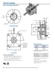
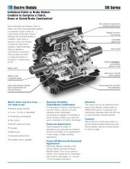
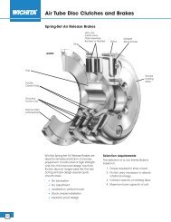
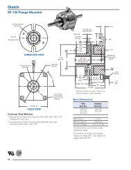
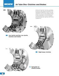
<strong>Clutch</strong>PC-500See page 230 for details onDrive Pin mountings.3.468.171 Max.4ARMATURE VIEW5.937Max.Dia.1/2-14 NPSM Am. std.straight pipe tap.5.062Dia.1.50Max..453See page252 fordetails onBushings..062 WhenNew.968.6251.187 1.3753.187Shaft Size .500 – 1.250Static Torque40 lb.ft.Maximum Speed5,400 rpmStandard Voltage D.C. 6, 24, 90MAGNET VIEWAll dimensions are nominal unlessotherwise noted.Information on inertia and weightsbegins on page 239. Coil data is onpages 250 and 251.Customer Shall Maintain:1. Armature mounting to be concentric withmagnet hub assembly within .006 T.I.R.72
Drawing I-257162<strong>Clutch</strong>PC-5002-11-11-24-11(Shipped Assembled)45376Item Description Part Number Qty.1 Magnet Hub 5300-541-001 11-1 Collector Ring 5300-749-001 11-2 Collector Ring Mounting Acc. 5300-101-002 12 Brushholder 5300-178-001 12-1 Brush 176-0001 43 Bushing* 11/2" to 1-1/4" Bore 180-0116 to 180-01284 Magnet 16 Volt. 5300-631-00224 Volt 5300-631-00390 Volt 5300-631-0054-1 Terminal Accessory 5311-101-001 15 Armature 5300-111-002 16 Autogap Accessory 5200-101-009 37 Mounting Accessory 5102-101-001 2How to Order:1. Specify Bore Size for Item 3.2. Specify Voltage for Item 4.3. See Controls Section.Example:PC-500 <strong>Clutch</strong> per I-25716 - 90 Volt3/4" BoreThese units, when used in conjunction with the correctWarner Electric conduit box, meet the standards set ofUL508 and are listed under guide card #NMTR2, file#59164.These units are CSA certified under file #LR11543.*See page 252 for specific part numbers.Refer to Service Manual P-203.73
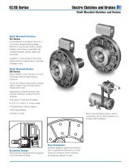
<strong>Clutch</strong>PC-825 Normal Duty2.562.171Max.5.750ARMATURE VIEWSee page 230 for details onDrive Pin mountings.1/2-14 NPSM Am.std. straight pipe tap.9.437Max.Dia.8.625Dia. 3.5625Dia.2.562Dia.1.5001.5937.781Dia.See page 252 for detailson Bushings..5621.3121.437.093 when new3.468 Max..062Min. Running ClearanceShaft Size .500 – 1.625Static Torque125 lb.ft.Maximum Speed4,000 rpmStandard Voltage D.C. 6, 24, 90COLLECTOR RING VIEWAll dimensions are nominal unlessotherwise noted.Information on inertia and weightsbegins on page 239. Coil data is onpages 250 and 251.74
Drawing I-255624-1<strong>Clutch</strong>PC-825 Normal Duty43177-16(ShippedAsembled)56-226-1Item Description Part Number Qty.1 Armature 5301-111-018 12 Autogap Accessory 5201-101-008 33 Mounting Accessory 5321-101-001 14 Magnet 16 Volt 5301-631-00224 Volt 5301-631-00490 Volt 5301-631-005†90 Volt LK Facing 5301-631-0114-1 Terminal Accessory 5311-101-001 15 Bushing* 11/2" to 1-5/8" Bore 180-0131 to 180-01496 Magnet Hub 1Left Hand (shown) 5301-541-001Right Hand 5301-541-0026-1 Collector Ring 5301-749-001 16-2 Collector Ring Accessory 5301-101-002 17 Brushholder 5300-178-001 17-1 Brush 176-0001 4How to Order:1. Specify Voltage for Item 4.2. Specify Bore Size for Item 5.3. Specify left hand or right hand hub for Item 6. (Bushingenters from magnet side for L.H. hub and from hubside for R.H.)4. See Controls Section.Example:PC-825 <strong>Clutch</strong> per I-25562 - 90 Volt,L.H. hub, 1" BoreThese units meet the standards of UL508 and are listedunder guide card #NMTR2, file #59164.These units are CSA certified under file #LR11543.*See page 252 for specific part numbers.Refer to Service Manual P-206.†Optional LK facing available. For more information,see page 232.75
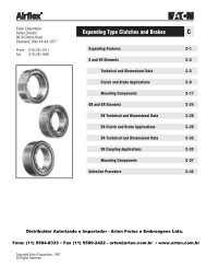
<strong>Clutch</strong>PC-825 Heavy Duty2.531.171Max.ARMATURE VIEW1.640 dia..271/.263 Dia. (5) holes equallyspaced on 2.015 dia. Mounting holesare within .003 of true positionrelative to pilot diameter.9.437Max.Dia.8.625Dia..093Max. Length ofCustomer Pilot2.3132.311PilotDia.1.3431.5931.5005.7507.781Dia.1/2-14 NPSM Am. std. straight pipe tap.1/4-28 UNF-3ASee page 252 for detailson Bushings..125.0621.312 1.437(Left HandMagnet HubShown).531.468 Max.3.656 Max..062Min. RunningClearanceShaft Size .500 – 1.625Static Torque125 lb.ft.Maximum Speed4,000 rpmStandard Voltage D.C. 6, 24, 90COLLECTOR RING VIEWCustomer Shall Maintain:1. Splined hub pilot diameter to be concentric with splinedarmature center of rotation within .010 T.I.R.2. Magnet hub shaft to be concentric with splined armaturecenter of rotation within .006 T.I.R.All dimensions are nominal unlessotherwise noted.Information on inertia and weightsbegins on page 239. Coil data is onpages 250 and 251.76
Drawing I-255631(ShippedAssembled)1-4<strong>Clutch</strong>PC-825 Heavy Duty1-21-11-51-386-25-18-125736-146(ShippedAssembled)Item Description Part Number Qty.1 Armature & SplinedAdapter Assembly 5321-111-001 11-1 Armature 5321-111-022 11-2 Splined Armature Adapter 104-0008 11-3 Autogap Accessory 5321-101-006 1Autogap Spring 808-0054 1Retainer Ring 748-0373 11-4 Button Head Screw 797-0272 31-5 Locknut 661-0004 32 Mounting Accessory 5201-101-001 13 Splined Hub 540-0146 14 Mounting Accessory 5321-101-001 15 Magnet 16 Volt 5301-631-00224 Volt 5301-631-00490 Volt 5301-631-005†90 Volt LK Facing 5301-631-0115-1 Terminal Accessory 5311-101-001 16 Magnet Hub Assembly 1Right Hand 5301-541-002Left Hand (shown) 5301-541-001Item Description Part Number Qty.6-1 Collector Ring 5301-749-001 16-2 Collector Ring Accessory 5301-101-002 17 Bushing, Taperlock* 180-0131 to 180-0149 18 Brushholder 5300-178-001 18-1 Brush 176-0001 4How to Order:1. Specify Voltage for Item 5.2. Specify Bore Size for Item 7.3. Specify left hand or right hand hub for Item 6.4. See Controls Section.Example:PC-825 <strong>Clutch</strong> per I-25563 - 90 Volt,L.H. hub, 1" BoreThese units meet the standards of UL508 and are listedunder guide card #NMTR2, file #59164. These units areCSA certified under file #LR11543*See page 252 for specific part numbers.Refer to Service Manual P-206.†Optional LK facing available. For more information, seepage 232.77
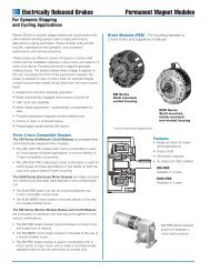
<strong>Clutch</strong>PC-1000 Normal Duty2.937.171Max.5.750ARMATURE VIEWSee page 230 for details onDrive Pin mountings.11.093Max.Dia. 10.296 Dia.5.252Dia.4.125Dia.1.7501.9067.781Dia.1/2-14 NPSM Am. std.straight pipe tap.See page 252 for detailson Bushings..5621.4531.750.093 When New3.906 Max..062Min. Running ClearanceShaft Size .500 – 2.500Static Torque240 lb.ft.Maximum Speed3,600 rpmStandard Voltage D.C. 6, 24, 90COLLECTOR RING VIEWAll dimensions are nominal unlessotherwise noted.Information on inertia and weightsbegins on page 239. Coil data is onpages 250 and 251.78
Drawing I-255824-1<strong>Clutch</strong>PC-1000 Normal Duty43177-16(ShippedAsembled)56-226-1Item Description Part Number Qty.1 Armature 5302-111-013 12 Autogap Accessory 5201-101-008 33 Mounting Accessory 5321-101-001 14 Magnet 16 Volt 5302-631-00324 Volt 5302-631-01490 Volt 5302-631-005†90 Volt LK Facing 5302-631-0014-1 Terminal Accessory 5311-101-001 15 Bushing* 11/2" to 2-1/2" Bore 180-0185 to 180-02176 Magnet Hub 1Left Hand (shown) 5302-541-001Right Hand 5302-541-0026-1 Collector Ring 5301-749-001 16-2 Collector Ring Accessory 5302-101-002 17 Brushholder 5300-178-001 1Item Description Part Number Qty.7-1 Brush 176-0001 4How to Order:1. Specify Voltage for Item 4.2. Specify Bore Size for Item 5.3. Specify left hand or right hand hub for Item 6. (Bushingenters from magnet side for L.H. hub and from hubside for R.H.)4. See Controls Section.Example:PC-1000 <strong>Clutch</strong> per I-25582 - 90 Volt,L.H. hub, 1" BoreThese units meet the standards of UL508 and are listedunder guide card #NMTR2, file #59164.These units are CSA certified under file #LR11543.*See page 252 for specific part numbers.Refer to Service Manual P-206.†Optional LK facing available. For more information, seepage 232.79
<strong>Clutch</strong>PC-1000 Heavy Duty2.875.171Max.ARMATURE VIEW2.562 dia..397/.388 Dia. (3) holes equally spaced on3.187 dia. Mounting holes are within .003 oftrue position relative to pilot diameter.11.093Max.Dia.10.296Dia..093Max. Length ofCustomer Pilot4.0013.999PilotDia.1.3751.9061.7505.7507.781Dia.1/2-14 NPSM Am. std.straight pipe tap.See page 252 for detailson Bushings.3/8-16 UNF-2A.125.062.5001.453 1.750(Left HandMagnet HubShown).843 Max.4.093 Max..062Min. RunningClearanceCOLLECTOR RING VIEWCustomer Shall Maintain:1. Splined hub pilot diameter to be concentric with splinedarmature center of rotation within .010 T.I.R.2. Magnet hub shaft to be concentric with splined armaturecenter of rotation within .006 T.I.R.Shaft Size .500 – 2.500Static TorqueMaximum Speed240 lb.ft.3,600 rpmStandard Voltage D.C. 6, 24, 90All dimensions are nominal unlessotherwise noted.Information on inertia and weightsbegins on page 239. Coil data is onpages 250 and 251.80
Drawing I-255831(ShippedAssembled)1-4<strong>Clutch</strong>PC-1000 Heavy Duty1-21-11-51-386-25-18-125736-146(ShippedAssembled)Item Description Part Number Qty.1 Armature & SplinedAdapter Assembly 5322-111-002 11-1 Armature 5322-111-036 11-2 Splined Armature Adapter 104-0009 11-3 Autogap Accessory 5322-101-004 1Autogap Spring 808-0061 1Retainer Ring 748-0374 11-4 Button Head Screw 797-0272 31-5 Locknut 661-0004 32 Mounting Accessory 5202-101-001 13 Splined Hub 540-0147 14 Mounting Accessory 5321-101-001 15 Magnet 16 Volt 5302-631-00324 Volt 5302-631-01490 Volt 5302-631-005†90 Volt LK Facing 5302-631-0015-1 Terminal Accessory 5311-101-001 16 Magnet Hub Assembly 1Right Hand 5302-541-002Left Hand (shown) 5302-541-001Item Description Part Number Qty.6-1 Collector Ring 5301-749-001 16-2 Collector Ring Accessory 5302-101-002 17 Bushing, Taperlock* 180-0185 to 180-0217 18 Brushholder 5300-178-001 18-1 Brush 176-0001 4How to Order:1. Specify Voltage for Item 5.2. Specify Bore Size for Item 7.3. Specify left hand or right hand hub for Item 6.4. See Controls Section.Example:PC-1000 <strong>Clutch</strong> per I-25583 - 90 Volt,L.H. hub, 1" BoreThese units meet the standards of UL508 and are listedunder guide card #NMTR2, file #59164.These units are CSA certified under file #LR11543*See page 252 for specific part numbers.Refer to Service Manual P-206.†Optional LK facing available. For more information,see page 232.81
<strong>Clutch</strong>PC-1225 Normal Duty3.500.171Max.1/2-13 UNC-3B5.750ARMATURE VIEWSee page 230 for details onDrive Pin mountings.12.625Dia.13.140Max.Dia.5.877Dia.4.625Dia.3.15637.781Dia.1/2-14 NPSM Am. std.straight pipe tap.See page 252 fordetails on Bushings..593.093 When New1.6404.562 Max..062 Min.RunningClearanceShaft Size .937 – 3.000Static TorqueMaximum Speed465 lb.ft.3,000 rpmStandard Voltage D.C. 6, 24, 90All dimensions are nominal unlessotherwise noted.Information on inertia and weightsCOLLECTOR RING VIEWbegins on page 239. Coil data is onpages 250 and 251.®U L82
Drawing I-25602<strong>Clutch</strong>PC-1225 Normal Duty44-13177-156-26-126(Shipped Assembled)Item Description Part Number Qty.1 Armature 5303-111-009 12 Autogap Accessory 5201-101-008 43 Mounting Accessory 5321-101-001 14 Magnet 16 Volt 5303-631-00524 Volt 5303-631-00790 Volt 5303-631-008†90 Volt LK Facing 5303-631-0014-1 Terminal Accessory 5311-101-001 15 Bushing* 115/16" to 3" Bore 180-0262 to 180-02956 Magnet Hub 1Left Hand (shown) 5303-541-001Right Hand 5303-541-0026-1 Collector Ring 5301-749-001 16-2 Collector Ring Accessory 5303-101-004 1Item Description Part Number Qty.7 Brushholder 5300-178-001 17-1 Brush 176-0001 4How to Order:1. Specify Voltage for Item 4.2. Specify Bore Size for Item 5.3. Specify left hand or right hand hub for Item 6. (Bushingenters from magnet side for L.H. hub and from hubside for R.H.)4. See Controls Section.Example:PC-1225 <strong>Clutch</strong> per I-25602 - 90 Volt, L.H. hub, 1" BoreThese units meet standards set forth in UL508 and arelisted under guide card #NMTR2, file #59164.These units are CSA certified under file #LR11543*See page 252 for specific part numbers.Refer to Service Manual P-207.†Optional LK facing available. For more information, seepage 232.83
<strong>Clutch</strong>PC-1225 Heavy Duty3.062 dia.3.468.171 Max.Max. Length ofCustomer Pilot3/8-16UNC-2A.0935.750ARMATURE VIEW.397/.388 Dia. (8) holes equally spaced on3.625 dia. Mounting holes are within .003 oftrue position relative to pilot diameter.13.14012.6254.3134.311Pilot Dia.1.5003.003.1567.781Dia.1/2-14 NPSM Am. std. straight pipe tap.RunningDia. Max.(Left HandMagnet HubShown)See page 252 fordetails on Bushings..125.562.0621.640 2.187.062 Min.RunningClearance.718 Max.4.875 Max.Shaft Size .937 – 3.000Static Torque465 lb.ft.Maximum Speed3,000 rpmStandard Voltage D.C. 6, 24, 90COLLECTOR RING VIEWCustomer Shall Maintain:1. Splined hub pilot diameter to be concentricwith splined armature center of rotation within .010 T.I.R.All dimensions are nominal unlessotherwise noted.Information on inertia and weightsbegins on page 239. Coil data is onpages 250 and 251.84
Drawing I-256031-4<strong>Clutch</strong>PC-1225 Heavy Duty1(ShippedAssembled)1-21-181-58-11-3 5-1576-26-13246(ShippedAssembled)Item Description Part Number Qty.1 Armature & SplinedAdapter Assembly 5323-111-001 11-1 Armature 5323-111-034 11-2 Splined Armature Adapter 104-0010 11-3 Autogap Accessory 5323-101-002 1Autogap Spring 808-0044 1Retainer Ring 748-0370 11-4 Button Head Screw 797-0281 41-5 Locknut 661-0005 42 Mounting Accessory 5202-101-001 13 Splined Hub 540-0148 14 Mounting Accessory 5321-101-001 15 Magnet 16 Volt 5303-631-00524 Volt 5303-631-00790 Volt 5303-631-008†90 Volt LK Facing 5303-631-0015-1 Terminal Accessory 5311-101-0016 Magnet Hub Assembly 1Right Hand 5303-541-002Left Hand (shown) 5303-541-001Item Description Part Number Qty.6-1 Collector Ring 5301-749-001 16-2 Collector Ring Accessory 5303-101-004 17 Bushing, Taperlock* 180-0262 to 180-0295 18 Brushholder 5300-178-001 18-1 Brush 176-0001 4How to Order:1. Specify Voltage for Item 5.2. Specify Bore Size for Item 7.3. Specify left hand or right hand hub for Item 6.4. See Controls Section.Example:PC-1225 <strong>Clutch</strong> perI-25603 - 90 Volt, L.H. hub, 1" BoreThese units meet the standards of UL508 and are listedunder guide card #NMTR2, file #59164.These units are CSA certified under file #LR11543.*See page 252 for specific part numbers.Refer to Service Manual P-206.†Optional LK facing available. For more information,see page 232.85
<strong>Clutch</strong>PC-1525 Normal Duty3.812.171Max.1/2-13 UNC-3B5.750ARMATURE VIEWSee page 230 for details onDrive Pin mountings.15.578Dia.16.250Max.Dia.8.500Dia.7.093Dia.3.18737.781Dia.1/2-14 NPSM Am. std.straight pipe tap..593.093 When New1.7504.796 Max..062 Min.RunningClearanceSee page 252 fordetails on Bushings.Shaft Size .937 – 3.000Static TorqueMaximum Speed700 lb.ft.2,000 rpmStandard Voltage D.C. 6, 24, 90All dimensions are nominal unlessotherwise noted.COLLECTOR RING VIEW®U LInformation on inertia and weightsbegins on page 239. Coil data is onpages 250 and 251.86
Drawing I-25628<strong>Clutch</strong>PC-1525 Normal Duty44-13177-156-26-126(Shipped Assembled)Item Description Part Number Qty.1 Armature 5304-111-004 12 Autogap Accessory 5201-101-008 43 Mounting Accessory 5321-101-001 24 Magnet 16 Volt 5304-631-00924 Volt 5304-631-01190 Volt 5304-631-010†90 Volt LK Facing 5304-631-0024-1 Terminal Accessory 5311-101-001 15 Bushing* 115/16" to 3" Bore 180-0262 to 180-02956 Magnet Hub 1Left Hand (shown) 5304-541-001Right Hand 5304-541-0026-1 Collector Ring 5301-749-001 16-2 Collector Ring Accessory 5304-101-004 1Item Description Part Number Qty.7 Brushholder 5300-178-001 17-1 Brush 176-0001 4How to Order:1. Specify Voltage for Item 4.2. Specify Bore Size for Item 5.3. Specify left hand or right hand hub for Item 6.(Bushing enters from magnet side for L.H. hub andfrom hub side for R.H.)4. See Controls Section.Example:PC-1525 <strong>Clutch</strong> per I-25628 - 90 Volt, L.H. hub, 1" BoreThese units meet standards set forth in UL508 and arelisted under guide card #NMTR2, file #59164.These units are CSA certified under file #LR11543*See page 252 for specific part numbers.Refer to Service Manual P-206.†Optional LK facing available. For more information,see page 232.87
<strong>Clutch</strong>PC-1525 Heavy Duty3.062 dia.3.781.171Max.Max. Length ofCustomer Pilot.0933/8-16UNC-2AARMATURE VIEW.397/.388 Dia. (8) holes (hub)equally spaced on 3.625 dia.Mounting holes are within .003of true position relative to pilotdiameter.16.25015.5784.3134.311Pilot Dia.1.5003.003.1875.7507.781Dia.1/2-14 NPSM Am. std.straight pipe tap.See page 252 fordetails on Bushings.RunningDia. Max.(Left HandMagnet HubShown).125.562.0621.750 2.312.062 Min.RunningClearance.718 Max.5.109 Max.Shaft Size .937 – 3.000Static Torque700 lb.ft.Maximum Speed2,000 rpmStandard Voltage D.C. 6, 24, 90COLLECTOR RING VIEWCustomer Shall Maintain:1. Splined hub pilot diameter to be concentricwith splined armature center of rotation within .010 T.I.R.All dimensions are nominal unlessotherwise noted.Information on inertia and weightsbegins on page 239. Coil data is onpages 250 and 251.88
Drawing I-256291-4<strong>Clutch</strong>PC-1525 Heavy Duty1(ShippedAssembled)1-21-11-681-58-11-3 5-1576-26-13246(ShippedAssembled)Item Description Part Number Qty.1 Armature & SplinedAdapter Assembly 5324-111-001 11-1 Armature 5324-111-034 11-2 Splined Armature Adapter 104-0011 11-3 Autogap Accessory 5323-101-002 1Autogap Spring 808-0044 1Retainer Ring 748-0370 11-4 Button Head Screw 797-0272 81-5 Locknut 661-0004 81-6 Retainer Plate 686-0003 12 Mounting Accessory 5202-101-001 13 Splined Hub 540-0148 14 Mounting Accessory 5321-101-001 25 Magnet 16 Volt 5304-631-00924 Volt 5304-631-01190 Volt 5304-631-010†90 Volt LK Facing 5304-631-0025-1 Terminal Accessory 5311-101-001 16 Magnet Hub Assembly 1Right Hand 5304-541-002Left Hand (shown) 5304-541-001Item Description Part Number Qty.6-1 Collector Ring 5301-749-001 16-2 Collector Ring Accessory 5304-101-004 17 Bushing, Taperlock* 180-0262 to 180-0295 18 Brushholder 5300-178-001 18-1 Brush 176-0001 4How to Order:1. Specify Voltage for Item 5.2. Specify Bore Size for Item 7.3. Specify left hand or right hand hub for Item 6.4. See Controls Section.Example:PC-1525 <strong>Clutch</strong> perI-25629 - 90 Volt, L.H. hub, 1" BoreThese units meet the standards of UL508 and are listedunder guide card #NMTR2, file #59164.These units are CSA certified under file #LR11543.*See page 252 for specific part numbers.Refer to Service Manual P-206.†Optional LK facing available. For more information,see page 232.Distribuidor Autorizado e Importador - <strong>Arten</strong> <strong>Freios</strong> e <strong>Embreagens</strong> Ltda.Fone: (11) 5594-8333 • Fax (11) 5589-2422 - arten@arten.com.br • www.arten.com.br89