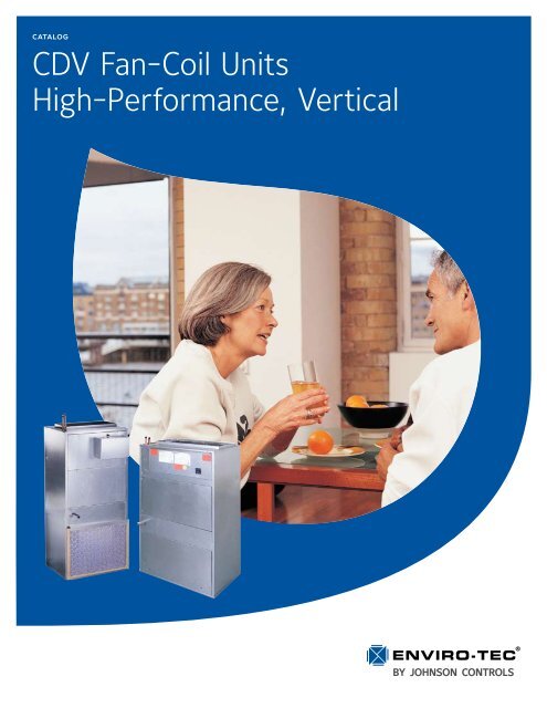
CDV Fan-Coil Units High-Performance, Vertical - Enviro-Tec
CDV Fan-Coil Units High-Performance, Vertical - Enviro-Tec
CDV Fan-Coil Units High-Performance, Vertical - Enviro-Tec
- No tags were found...

You also want an ePaper? Increase the reach of your titles
YUMPU automatically turns print PDFs into web optimized ePapers that Google loves.
<strong>CDV</strong> <strong>Fan</strong>-<strong>Coil</strong> <strong>Units</strong> <strong>High</strong>-<strong>Performance</strong>, <strong>Vertical</strong> Catalog: ET115.26-EG8 (909)COILS, PHYSICAL DATA<strong>Coil</strong>sENVIRO-TEC ® offers hot water, chilled water, and direct expansion (DX) coils for specific application with all <strong>CDV</strong>direct drive fan coils. ARI 410 certified and labeled, and strict on-site inspection before, during, and after installationguarantees the highest quality and performance available.STANDARD FEATURES• Designed, manufactured and tested by Johnson Controls• ARI 410 certified and labeled• 1/2" O.D. seamless copper tubes• <strong>High</strong> efficiency aluminum fin surface for optimizing heat transfer,pressure drop and carryover.• Mechanically expanded copper tubes leak tested to aminimum 450 PSIG air pressure under water• Manual air vent plug on all water coils• Copper ODM sweat connections• 300 PSIG working pressure at 200°F• Evaporator coils are factory sealed and charged with minimumof 5 PSIG nitrogen or refrigerated dry air• Refrigerant coils are provided with a fixed orifice meteringdevice (distributor-eliminator)• 0.016" tube wall thicknessOPTIONAL FEATURES• Automatic air vents on water coils• Stainless steel coil casings• 0.025" tube wall thickness• DX coils are heat pump compatibleUNITSIZEAUXILIARYHEATING COILcoil face area and filter dataCOOLINGCOILNOTES:1. Standard filters are 1" throwaway; optional filters are 2" throwaway.2. <strong>Coil</strong> face areas are measured in square feet [square meters].3. Filter sizes are measured in inches [millimeters].NOMINAL FILTER SIZESFACE AREA FACE AREA WITH FRONT RETURN WITH BOTTOM RETURN04 0.9 [0.08] 1.3 [0.12] 16 x 22 x 1 [406 x 559 x 25] (2) 14 x 10.5 x 1 [356 x 267 x 25]06 0.9 [0.08] 1.6 [0.15] 16 x 22 x 1 [406 x 559 x 25] (2) 14 x 10.5 x 1 [356 x 267 x 25]08 1.2 [0.11] 1.8 [0.17] 16 x 22 x 1 [406 x 559 x 25] (2) 14 x 10.5 x 1 [356 x 267 x 25]10 2.0 [0.19] 2.6 [0.24] 16 x 29 x 1 [406 x 737 x 25] (2) 14 x 17 x 1 [356 x 432 x 25]12 2.0 [0.19] 2.9 [0.27] 16 x 29 x 1 [406 x 737 x 25] (2) 14 x 17 x 1 [356 x 432 x 25]16 3.3 [0.31] 4.0 [0.37] (2) 16 x 23 x 1 [406 x 584 x 25] (2) 17 x 22.5 x 1 [432 x 572 x 25]20 3.3 [0.31] 5.1 [0.47] (2) 16 x 23 x 1 [406 x 584 x 25] (2) 17 x 22.5 x 1 [432 x 572 x 25]ENVIRO-TEC 7
<strong>CDV</strong> <strong>Fan</strong>-<strong>Coil</strong> <strong>Units</strong> <strong>High</strong>-<strong>Performance</strong>, <strong>Vertical</strong> Catalog: ET115.26-EG8 (909)electric heatStandard Features• ETL listed as an assemblyfor safety compliance• Single point power connection• Mounted in reheat position• Automatic reset primary and back-upsecondary thermal limits• Internal wiring rated at 105°C• Integral electric heat assembly withremovable element for easy serviceoptional features• Silent solid state relays• Door interlocking disconnect switch• Main fusing• Manual reset secondary limitsuseful formulaskW* = CFM x ∆T x 1.085**34131Ø AMPs = kW x 1000Volts* 1kW = 3413 BTU/H** Capacity at sea levelAltitude Considerations:Reduce by 0.034 for each 1000 ft. of altitudeabove sea level.Example: 5000 ft./1000 ft. = 55 x 0.034 = 0.171.085 - 0.17 = 0.915ELECTRICAL CALCULATIONS INFORMATION1. Refer to MCA/MOP calculator at www.enviro-tec.com for MCA and/or MOP calculations.2. Non-Fused Door Interlock Disconnect Switch shall be sized according to MCA.3. Fused Door Interlock Disconnect Switch and Main Fusing shall be sized according to MOP.UNITSIZE04060810121620Electric Heat Selection Chart (AMPs)MBH 6.83 8.53 10.24 11.95 13.65 17.07 20.48 23.89 27.30 30.72 34.13 37.54 40.96 44.37KW 2.0 2.5 3.0 3.5 4.0 5.0 6.0 7.0 8.0 9.0 10.0 11.0 12.0 13.0VOLTSAMPS115 17.4 21.8 26.1 30.5 34.8 43.5208 9.6 12.0 14.4 16.8 19.2 24.1230 8.7 10.9 13.1 15.2 17.4 21.8277 7.2 9.0 10.8 12.6 14.4 18.1115 17.4 21.8 26.1 30.5 34.8 43.5208 9.6 12.0 14.4 16.8 19.2 24.1 28.9 33.7 38.5230 8.7 10.9 13.1 15.2 17.4 21.8 26.1 30.5 34.8277 7.2 9.0 10.8 12.6 14.4 18.1 21.7 25.3 28.9115 17.4 21.8 26.1 30.5 34.8 43.5208 9.6 12.0 14.4 16.8 19.2 24.1 28.9 33.7 38.5 43.3230 8.7 10.9 13.1 15.2 17.4 21.8 26.1 30.5 34.8 39.2 43.5277 7.2 9.0 10.8 12.6 14.4 18.1 21.7 25.3 28.9 32.5 36.1 39.7115 17.4 21.8 26.1 30.5 34.8 43.5208 9.6 12.0 14.4 16.8 19.2 24.1 28.9 33.7 38.5 43.3230 8.7 10.9 13.1 15.2 17.4 21.8 26.1 30.5 34.8 39.2 43.5277 7.2 9.0 10.8 12.6 14.4 18.1 21.7 25.3 28.9 32.5 36.1 39.7 43.3 46.9115 34.8 43.5208 19.2 24.1 28.9 33.7 38.5 43.3230 17.4 21.8 26.1 30.5 34.8 39.2 43.5277 14.4 18.1 21.7 25.3 28.9 32.5 36.1 39.7 43.3 46.9115 34.8 43.5208 19.2 24.1 28.9 33.7 38.5 43.3230 17.4 21.8 26.1 30.5 34.8 39.2 43.5277 14.4 18.1 21.7 25.3 28.9 32.5 36.1 39.7 43.3 46.9115 34.8 43.5208 19.2 24.1 28.9 33.7 38.5 43.3230 17.4 21.8 26.1 30.5 34.8 39.2 43.5277 14.4 18.1 21.7 25.3 28.9 32.5 36.1 39.7 43.3 46.9NOTES:1. Shaded areas indicate kW and voltage options not available.2. Available voltages are single phase, 60 hertz.ENVIRO-TEC 9
Catalog: ET115.26-EG8 (909)<strong>CDV</strong> <strong>Fan</strong>-<strong>Coil</strong> <strong>Units</strong> <strong>High</strong>-<strong>Performance</strong>, <strong>Vertical</strong>FAN PERFORMANCEGeneral <strong>Fan</strong> Notes1. <strong>Fan</strong> curves depict actual performance of each motor tap without any additional fan balance adjustment. Actual capacitieswhich fall below each curve can be obtained by adding an adjustment device. <strong>Units</strong> should not be run prior to installation ofdownstream ductwork; otherwise, damage to the motor may result. The minimum external static pressure required is 0.1inches w.g.2. ENVIRO-TEC ® fan coil units are equipped with permanent split-capacitor (PSC) motors with three separate speeds (<strong>High</strong>,Medium and Low) which provides variable horsepower outputs. Most often, size selections are conservative and actual CFMrequirements and/or external static pressure requirements are lower than those specified. In this case, the unit fan motorcan be run at low or medium tap, substantially reducing the operating cost of the unit.3. All fan curves are for 115/1/60 motors and include losses for cabinet, electric heater, 3 or 4 row coil, and clean 1" throwawayfilter. For other configurations, adjust performance curves based on pressure losses for individual components found onpage 7.4. See page 12 for fan motor electrical data.<strong>CDV</strong> 04 • 3 and 4 Row <strong>Coil</strong>s<strong>CDV</strong> 06 • 3 and 4 Row <strong>Coil</strong>s1.21.01.10.91.00.90.80.80.7ESP (IN. W.G.)0.70.60.5ESP (IN. W.G.)0.60.50.40.40.30.20.1LOWHIGHMED.0.30.20.1LOWMED.HIGH0.00.00 100 200 300 400 500 600 7000 100 200 300 400 500 600 700 800CFM3 ROW COIL4 ROW COILCFM3 ROW COIL4 ROW COIL<strong>CDV</strong> 08 • 3 and 4 Row <strong>Coil</strong>s<strong>CDV</strong> 10 • 3 and 4 Row <strong>Coil</strong>s1.11.010.90.90.80.80.7ESP (IN. W.G.)0.70.60.50.4ESP (IN. W.G.)0.60.50.40.30.2HIGH0.30.2HIGH0.10LOWMED.0.10LOWMED.0 200 400 600 800 1000 12000 200 400 600 800 1000 1200 1400CFM3 ROW COIL4 ROW COILCFM3 ROW COIL4 ROW COIL10 ENVIRO-TEC
<strong>CDV</strong> <strong>Fan</strong>-<strong>Coil</strong> <strong>Units</strong> <strong>High</strong>-<strong>Performance</strong>, <strong>Vertical</strong> Catalog: ET115.26-EG8 (909)FAN PERFORMANCE CURVES1.2<strong>CDV</strong> 12 • 3 and 4 Row <strong>Coil</strong>s1.2<strong>CDV</strong> 16 • 3 and 4 Row <strong>Coil</strong>s1.01.0ESP (IN.W.G.)0.80.60.4ESP (IN.W.G.)00.814051362132812671216 0.6116311081029980950 0.4000204519351820169515551400122510158000000.2LOWHIGHMED.0.00 200 400 600 800 1000 1200 1400 16003 ROW COILCFM4 ROW COIL13151272 0.2HIGH125412031171LOWMED.11221070 0.01004950 0 500 1000 1500 2000 250003 ROW COILCFM4 ROW COIL16001550150014251330121010509008000<strong>CDV</strong> 20 • 3 and 4 Row <strong>Coil</strong>s1.00.90.8ESP (IN.W.G.)0.70.60.50.40.30.2HIGH0.1MED.LOW0.00 500 1000 1500 2000 25003 ROW COILCFM4 ROW COIL19951900184117821657154314261300116780000158515481500145014001350130012501150100080002375ENVIRO-TEC ® offers the industry’s first web-based fan coil rating and selection program for complete unit, coiland sound selection. See your representative for more information.ENVIRO-TEC 11
Catalog: ET115.26-EG8 (909)motor, fan and sound datamotor and fan datasound data<strong>CDV</strong> <strong>Fan</strong>-<strong>Coil</strong> <strong>Units</strong> <strong>High</strong>-<strong>Performance</strong>, <strong>Vertical</strong>UNIT SIZE MOTOR TAPMOTOR NUMBER OFAMPS(QTY.) HP FANS 115V 208V 230V 277VHI (1) 1/62.7 1.4 1.4 1.004MED (1) 1/8 12.4 0.9 0.9 0.9LOW (1) 1/10 2.2 0.6 0.6 0.8HI (1) 1/62.7 1.4 1.4 1.006MED (1) 1/8 12.4 0.9 0.9 0.9LOW (1) 1/10 2.2 0.6 0.6 0.8HI (1) 1/44.9 2.2 2.2 2.008MED (1) 1/5 14.1 1.5 1.5 1.7LOW (1) 1/8 3.2 1.1 1.1 1.4HI (1) 1/44.9 2.2 2.2 2.010MED (1) 1/5 14.1 1.5 1.5 1.7LOW (1) 1/8 3.2 1.1 1.1 1.4HI (1) 1/29.6 4.0 4.0 3.612MED (1) 1/3 19.3 2.7 2.7 2.9LOW (1) 1/4 8.8 2.0 2.0 2.8HI (2) 1/49.8 4.4 4.4 4.016MED (2) 1/5 28.2 3.0 3.0 3.4LOW (2) 1/8 6.4 2.2 2.2 2.8HI (2) 1/49.8 4.4 4.4 4.020MED (2) 1/5 28.2 3.0 3.0 3.4LOW (2) 1/8 6.4 2.2 2.2 2.8NOTES:1. Motor electrical data is nameplate data. Actual data will vary with application.2. 230 volt motor is nameplated for 208-230/1/60. Use 230 volt motor data for 208 volt applications.UNIT SIZE FAN SPEED CFM RPMTOTAL SOUND POWER LEVELOCTAVE BAND / CENTER FREQUENCY (HZ)2/125 3/250 4/500 5/1000 6/2000 7/4000 8/8000HI 610 1107 70 62 57 53 51 49 4204 MED 570 1040 69 61 55 51 49 49 42LOW 515 949 69 63 58 53 50 49 42HI 750 1050 78 71 63 59 57 56 4906 MED 650 895 73 66 59 55 53 51 47LOW 540 735 68 61 54 50 48 45 41HI 1050 1114 75 70 64 59 57 56 4908 MED 1000 1023 72 68 62 57 55 54 46LOW 895 877 69 64 58 53 51 48 40HI 1275 1051 74 70 64 64 62 61 5310 MED 1050 849 70 64 60 59 56 55 47LOW 825 671 65 58 54 53 50 48 40HI 1490 1089 77 72 67 68 68 67 6212 MED 1420 1035 76 71 66 67 66 65 60LOW 1320 964 74 69 64 65 64 63 58HI 2300 1099 77 71 67 65 64 63 5716 MED 2030 988 75 69 65 63 61 60 54LOW 1600 785 71 63 59 57 55 54 46HI 2290 1088 77 73 68 66 64 64 5820 MED 1970 941 76 69 65 63 61 60 54LOW 1590 769 71 64 60 57 56 53 46NOTES:1. Sound data tested in accordance with ARI 350-86.2. Sound levels are expressed in decibels, dB RE: 1 x 10-12 watts.3. Total sound power level data based on fan CFM at corresponding motor tap with 115/1/60 volt motor, 0.0" external staticpressure and standard rated internal pressure losses.12 ENVIRO-TEC
<strong>CDV</strong> <strong>Fan</strong>-<strong>Coil</strong> <strong>Units</strong> <strong>High</strong>-<strong>Performance</strong>, <strong>Vertical</strong> Catalog: ET115.26-EG8 (909)dimensional datamodel <strong>CDV</strong> vertical unitsDrawings are not to scale and not for submittal or installation purposes.Without Electric HeatFront ViewWith Electric HeatSide ViewFront ViewDimensionsSide ViewNOTES:1. All dimensions are inches [millimeters] +/- 1/4" [6mm]. Metric values are soft conversion.2. Front access only is required for installation and service.3. Right hand unit shown, left hand unit opposite.ENVIRO-TEC 13
Catalog: ET115.26-EG8 (909)<strong>CDV</strong> <strong>Fan</strong>-<strong>Coil</strong> <strong>Units</strong> <strong>High</strong>-<strong>Performance</strong>, <strong>Vertical</strong>dimensional datasupply plenum with double deflection grilleDrawings are not to scale and not for submittal or installation purposes.UNIT SIZE A B CSUPPLY GRILLEW x H04-08 15" [381] 22" [559] 15" [381] 18" x 8" [457 x 203]10-12 18" [457] 29" [737] 18" [457] 24" x 12" [610 x 305]16-20 18" [457] 46" [1168] 18" [457] 40" x 12" [1016 x 305]NOTES:1. All dimensions are inches [millimeters] +/- 1/4" [6mm]. Metric values are soft conversion.2. C-dimension adds to basic unit height.Mixing Box SectionDrawings are not to scale and not for submittal or installation purposes.End ViewSide ViewUNIT SIZE A B CDE04-08 22" [559] 15" [381] 15" [381] 15" [381] 3 1/2" [89]10-12 29" [737] 18" [457] 18" [457] 20" [508] 4 1/2" [114]16-20 46" [1168] 18" [457] 18" [457] 36" [914] 5" [127]NOTES:1. All dimensions are inches [millimeters] +/- 1/4" [6mm]. Metric values are soft conversion.2. Return air plenum (one inlet, no dampers) is available in lieu of mixing box section.3. C-dimension adds to basic unit height.4. Linkage and actuator for damper control shall be provided/installed by others.14 ENVIRO-TEC
<strong>CDV</strong> <strong>Fan</strong>-<strong>Coil</strong> <strong>Units</strong> <strong>High</strong>-<strong>Performance</strong>, <strong>Vertical</strong> Catalog: ET115.26-EG8 (909)guide specificationsGENERALFurnish and install ENVIRO-TEC ® Model <strong>CDV</strong> <strong>Vertical</strong>Concealed Direct Drive <strong>Fan</strong> <strong>Coil</strong> Unit where indicatedon the plans and specifications. <strong>Units</strong> shall be completelyfactory assembled, tested and shipped as onepiece except where noted.All units shall be capable of meeting or exceeding thescheduled capacities for cooling, heating, and airdelivery. All unit dimensions for each model and sizeshall be considered maximums. <strong>Units</strong> shall be ETLlisted in compliance with UL/ANSI Standard 1995, andbe certified as complying with the latest edition of ARIStandard 440.CONSTRUCTIONAll units shall be fabricated of heavy gauge galvanizedsteel, able to meet 125 hour salt spray test per ASTMB-117. All exterior panels shall be insulated with 1/2"thick fiberglass insulation rated for a maximum air velocityof 5000 f.p.m. In addition to using adhesivecomplying with NFPA 90A and 90B, the insulation shallincorporate a secondary mechanical fastener attachedto the unit casing wall (weld pin). Adhesive as the onlymethod of fastening the insulation to the casing is notacceptable. Insulation shall conform to UL 181 for erosion,ASTM C-1071 for thermal and sound absorbingmaterial, NFPA 90A and 90B for fire and smoke, andcarry a 25/50 Flame Spread and Smoke DevelopedRating per ASTM E-84 and UL 723.All units shall have a minimum 1" duct collar on thedischarge. All access panels shall be fully insulatedand attached with standard fasteners on at least twoopposite sides. No coil, drain piping, or electrical connectionsshall pass through any access panel.Option: Provide foil faced insulation in lieu of matt facedinsulation. Foil insulation shall meet or exceed therequirements stated above, and in addition meet ASTMStandards C-665 and C-1136 for mold, mildew, andhumidity resistance. Insulation shall be lined with aluminumfoil, fiberglass scrim reinforcement, and #30 kraftpaper laminated together with a flame resistant adhesive.All exposed edges shall be sealed to prevent anyfibers from reaching the air stream.Option: Provide elastomeric closed cell foam insulationin lieu of standard. Insulation shall meet all requirementsof NFPA 90-A flame and smoke spreadand melting point, as well as ASTM G-21 for bacterialand fungi resistance. Polyethylene insulation is notacceptable.Each unit shall be furnished with a one-piece heavygauge galvanized steel drain pan with welded cornerconstruction.Option: Provide a single wall primary drain pan constructedentirely of heavy gauge stainless steel forsuperior corrosion resistance. Stainless steel drainpans shall meet or exceed the requirements statedabove.SOUND<strong>Units</strong> shall have published sound power level datatested in accordance with ARI Standard 350-86.FAN ASSEMBLYUnit fan shall be dynamically balanced, forwardlycurved, direct drive DWDI wheel with 18 gauge galvanizedchromate coated double inlet scroll. Motor shallinclude torsion flex suspension mount affixed to scrollusing permanently attached mounting studs. Motormount shall be secured with Nylock ® lock nuts. Blowerscroll shall be mounted to fan bulkhead with 18 gaugemounting rail in a manner to allow no metal-to-metalcontact with fan bulkhead.Blower motor shall be high efficiency, permanently lubricatedsleeve bearing, permanent split-capacitor type withthermal overload protection and three separate horsepowertaps. Single speed motors are not acceptable.The fan motor shall be unpluggable from the electricalleads at the motor case for simplified removal.Option: Provide an electronic (SCR) fan speed controllerfor aid in balancing the fan capacity. The speedcontroller shall have a turn down stop to prevent thepossibility of harming the motor bearings, and incorporateelectrical noise suppression to minimize noise onthe incoming power lines.COILSAll unit coils shall be rated in accordance withARI 410.All coils shall be 1/2" O.D. seamless copper tubes shallbe mechanically expanded to provide an efficient bondbetween tube and fin. All water coils shall be providedwith a manual air vent fitting to allow for coil venting.Valve core type vent fittings shall not be accepted.All chilled water, hot water, and direct expansion (DX)coils shall have 0.016" tube wall thickness.ENVIRO-TEC 15