You also want an ePaper? Increase the reach of your titles
YUMPU automatically turns print PDFs into web optimized ePapers that Google loves.
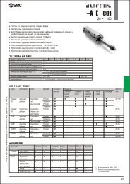
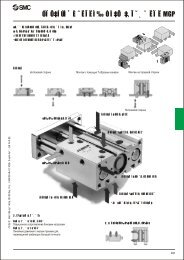
Process PumpAutomatically Operated Type<strong>Series</strong> <strong>PAF</strong>Piping and Operation: Automatically Operated Type (<strong>PAF</strong>3410)Piping diagramPilot air supply portAIR SUPDischargeportFLUID OUTSilencerOptionSuction portFLUID INPilot air exhaust portAIR EXHCautionMounting orientation of the pump is set with the mounting bracket facing downward. Air to be supplied to the air supply port should be clean and filtered through a filter, or a mist separator etc. Air with foreign matter or drainage etc. will have negative effects onthe built-in solenoid valve and will lead to malfunction.Maintain the proper tightening torque for fittings and mounting bolts, etc. Looseness can cause problems such as fluid and air leaks, whileover tightening can cause damage to threads and parts, etc.Operation Refer to circuit example (1)1. Connect air piping to the air supply port and connect piping for the fluid to be transfered to the suction port and the discharge port .2. Using a regulator, set the pilot air pressure within the range of 0.2 to 0.5 MPa. Then, the pump will operate when power is applied tothe 3 port solenoid valve of the air supply port , the sound of exhaust begins from the air exhaust port and fluidwill flow from the suction port to the discharge port .At this time, the ball valve on the discharge side is in an open state. The pump performs suction with its own power even without priming.(Dry state suction lifting range: max. 1 m) To restrict exhaust noise, attach a silencer (AN200-02: option) to the air exhaust port .3. To stop the pump, exhaust the air pressure being supplied to the pump with the 3 port solenoid valve of the air supply port . The pump stops even when the ball valve on the discharge side is closed. But the pressure supply to the pump should be exhaustedquickly.1. Adjustment of the flow rate from the discharge port is performed with a ball valve connected to the discharge side or athrottle connected to the air exhaust side. For adjustment on the air side, use of a silencer with throttle ASN2 (port size 1/4) or a needlevalve connected to the air exhaust port is effective. Refer to circuit example (1).2. When operating with a discharge flow rate below the specification range, provide a by-pass circuit on the discharge side to the suctionside to ensure the minimum flow rate inside the process pump. With a discharge flow rate below the minimum flow rate, the processpump may stop due to unstable operation. Refer to circuit example (2). (Minimum flow rate: 1 l/min)When the pump stops during operation, press the reset button. This makes it possible to restore operation in case the switching valve becomesclogged due to foreign matter in the supply air.Circuit example (1)Circuit example (2)For the related products, refer topage 13.Air filterAir supply3 portsolenoid valveProcess PumpRegulatorAIR FLUIDSUP OUTAIREXHFLUIDINStrainerBall valveProcess PumpBy-passSilencerThrottleTransfer fluid7