
Create successful ePaper yourself
Turn your PDF publications into a flip-book with our unique Google optimized e-Paper software.
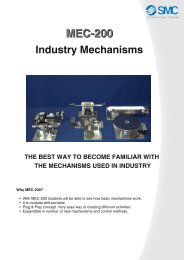
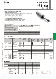
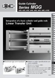
CAT.EUS100-59 A -UKClean Wet <strong>Series</strong>Process Pump<strong>Series</strong> <strong>PAF</strong>3000Body materialNewPFADiaphragm/Seal materialPTFEOne pump is compatible with various fluids. Light weightand Compact140 mm116 mm Weight: 1.3 kg(Air operated, without foot bracket) Non-Metallic Exterior(No external metal parts are used.)119 mm
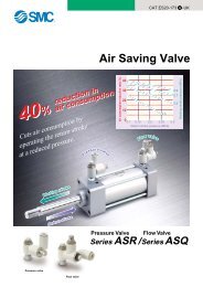
Dual PPS/PFA constructionWithstand pressure and heat cycle performance have been increased.Check ballPTFEDiaphragm holding boltNew PFADiaphragmDenaturedPTFESide coverPPSPortNew PFAValve seatNew PFASide coverNew PFALarge flow rateThe flow rate has been increased by 50%even though it is almost the same size as the PA3 series.Max. flow rate: 20 l/min (automatically operated)VariationsModelModymaterialDiaphragmmaterialDischarge flowrate (l/min)Fitting typeOptionAutomaticallyoperatedAir operated<strong>PAF</strong>3410<strong>PAF</strong>3413New PFADenatured PTFE1 to 201 to 15Female threadTube extensionWith nutFootSilencerFemale threadTube extensionWith nutFeatures 1
Process Pump:Automatically Operated Type (Internal Switching Type)Air Operated Type (External Switching Type)<strong>Series</strong> <strong>PAF</strong>3000Female thread <strong>PAF</strong>341 0 03Symbol03ActuationNote 1)ActuationAutomatically operatedAir operatedThread typeSymbol-NFNote 2)TypeRcNPTGHow to OrderPort sizeSymbol03OptionSymbol-BNPort size3/8"OptionNoneWith footWith silencerApplicable actuationAutomatically operatedAir operated—∗ When more than one option is required, add suffix in alphabetical order.Tube extension <strong>PAF</strong>341 0Symbol03ActuationNote 1)ActuationAutomatically operatedAir operatedSymbol13PTubing size13Main fluid connection size1/2"OptionSymbol-BNThread typeSymbol-NFOptionNoneWith footWith silencerApplicable actuationAutomatically operatedAir operated—∗ When more than one option is required, add suffix in alphabetical order.TypeRcNPTGNote 2)AIR SUPWith nut <strong>PAF</strong>341 0 S 1 S 13SymbolSymbol03FLUID OUTActuationNote 1)ActuationAutomatically operatedAir operatedSymbol131319191319Symbol1IN side45Fitting typeFitting typeLQ1Fitting size45OUT side54OptionSymbol-BNThread typeSymbol-NFOptionNoneWith footWith silencerTypeRcNPTGNote 2)Applicable actuationAutomaticallyoperatedAir operated—∗ When more than one option is required, add suffix inalphabetical order.AIR EXH FLUID INAutomatically operated typeP1P2FLUID OUTNote 1) The port size of the pilot port is as follows. Automatically operated type is 1/4"; Air operated type is 1/8".Note 2) The thread type is applied to the pilot port thread and the pipe connection female thread.FLUID INAir operated type1
<strong>SMC</strong><strong>SMC</strong><strong>SMC</strong><strong>SMC</strong><strong>SMC</strong><strong>Series</strong> <strong>PAF</strong>Union elbowEPPanel mount unionHow to Order Fittings for Products with Nut (<strong>PAF</strong>341S <strong>Series</strong>)Fittings compatible for the process pump with nut / <strong>PAF</strong>341S.For the case when using the process pump with nut, use the fittings which have one nut (including the insert bushing)removed.Union teeUnionLQ1Fitting typeT<strong>SMC</strong>UE 41 SApplicable tubing sizeClass4455No.1212A nut (including the insert bushing)is removed from one locationApplicable tubing size (mm)12 x 1010 x 819 x 1612 x 10ReducingClass4455No.ABABApplicable tubing size (inch)1/2" x 3/8"3/8" x 1/4"3/4" x 5/8"1/2" x 3/8"Note) Select the fitting after confirming the IN / OUT side fitting size and fitting type.Reducing: Basic size : With reducerOrdering Example<strong>PAF</strong>3410S-1S13Process pumpTubing size12 x 10OUT sideLQ1E41-SUnion elbowLQ1U4B-SUnionIN sideTubing size3/8" x 1/4"<strong>PAF</strong>3410S-1S13 1LQ1E41-S (Union elbow) 1LQ1U4B-S (Union) 1Note) Fittings which are ordered with the process pump at the same time will be shipped in a separate package.2
Process PumpAutomatically Operated Type<strong>Series</strong> <strong>PAF</strong>SpecificationsOperation methodPortsizeModelDischarge flow rateAverage discharge pressurePilot air pressureAir consumptionSuctionliftNoiseWithstand pressureService lifeOperating fluid temperatureAmbient temperatureRecommended operation cycleWeight (without foot bracket)MountingPackagingMain fluid: Suction/Discharge portPilot air: Supply/Exhaust portDryWet<strong>PAF</strong>3410Automatically operatedRc, G, NPT 1/4"1 to 20 l/min Note)80 dB (A) or less(Option: with silencer, AN200)Note) Values in the table are measured at room temperature using clean water.—1.6 kgRc, G, NPT 3/8" female thread, 1/2" tube extension0 to 0.4 MPa0.2 to 0.5 MPa (for 0 to 60°C)230 l/min (ANR) or lessUp to 1 m (inside the pump is dry)Up to 4 m (with fluid inside the pump)0.75 MPa50 million cycles (for water)0 to 90°C (with no freezing)0 to 70°C (with no freezing)Horizontal (mounting on the bottom surface)Clean double packaging<strong>PAF</strong>3413Air operatedRc, G, NPT 1/8"1 to 15 l/min Note)80 dB (A) or less(excluding the noise from the quick exhaustand solenoid valve)2 to 4 Hz1.3 kg3
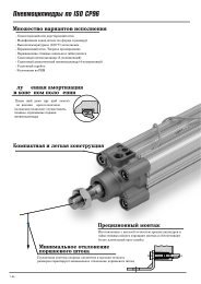
<strong>Series</strong> <strong>PAF</strong>Performance Curve: Automatically Operated Type<strong>PAF</strong>3410 Flow Characteristics0.5<strong>PAF</strong>3410 Air Consumption200Discharge pressure (MPa)0.40.30.20.1SUP = 0.5 MPaSUP = 0.4 MPaSUP = 0.3 MPaSUP = 0.2 MPaAir consumption (l/min)15010050SUP = 0.2 MPaSUP = 0.5 MPaSUP = 0.4 MPaSUP = 0.3 MPa00 510 15 20 2500510 15 20 25Discharge rate (l/min)Discharge rate (l/min)Selection from Flow Characteristic Graph (<strong>PAF</strong>3410)Required specifications example:Find the pilot air pressure and the pilot air consumption for a discharge rate of 6 l/min and a discharge pressure of 0.25 MPa. ∗ If the total lifting height is required instead of the discharge pressure, discharge pressure of 0.1 MPa corresponds to a total lift of 10 m.Selection procedures:1. First mark the intersection point for a discharge rate of 6 l/min and a discharge pressure of 0.25 MPa.2. Find the pilot air pressure for the marked point. In this case, the point is between the discharge curves for SUP = 0.3 MPa and SUP =0.4 MPa, and based on the proportional relationship between these lines, the pilot air pressure for this point is approximately 0.35 MPa.3. Next, find the air consumption rate. Trace the discharge rate, 6 l/min, up to the point between the discharge curves for SUP = 0.3 MPaand 0.4 MPa, then trace to the Y-axis, finding the air consumption to be around 55 l/min (ANR).Cautionq These flow characteristics are for fresh water (viscosity 1 mPa·s, specific gravity 1.0).w The discharge rate differs greatly depending on the properties (viscosity, specific gravity) of the fluid being transferredand the operating conditions (lifting range, transfer distance), etc.e Use 0.75 kW per 100 l/min of air consumption as a guide for the relationship of the air consumption to the compressor.Viscosity Characteristics (Flow rate correction for viscous fluids)Ratio of discharge rate against fresh water (%)1005001 10 100 1000Viscosity (mPa·s)Selection from Viscosity Characteristic GraphRequired specifications example:Find the pilot air pressure and pilot air consumption for a dischargerate of 2.7 l/min, with a discharge pressure of 0.25 MPa, anda viscosity of 100 mPa·s.Selection procedures:1. First find the ratio of the discharge rate against fresh waterwhen the viscosity is 100 mPa·s from the graph on the left. It isdetermined to be 45%.2. Next, in the required specification example, the viscosity is 100mPa·s and the discharge rate is 2.7 l/min. Since this is equivalentto 45% of the discharge rate for fresh water, 2.7 l/min ÷0.45 = 6 l/min, indicating that a discharge rate of 6 l/min is requiredfor fresh water.3. Finally, find the pilot air pressure and the pilot air consumptionbased on selection from the flow characteristic graphs.CautionViscosities up to 1000 mPa·s can be used.Dynamic viscosity ν = Viscosity µ/Density ρ.µν = ρν(10 –3 m 2 /s) = µ(mPa·s)/ρ(kg/m 3 )4
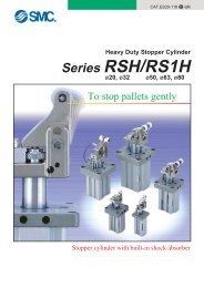
Process PumpAir Operated Type<strong>Series</strong> <strong>PAF</strong>Performance Curve: Air Operated Type<strong>PAF</strong>3413 Flow CharacteristicsDischarge pressure (MPa)<strong>PAF</strong>3413 Air Consumption (4 Hz)200Air consumption (l/min)15010050005SUP = 0.5 MPaSUP = 0.4 MPaSUP = 0.3 MPaSUP = 0.2 MPa<strong>PAF</strong>3413 Air Consumption (3 Hz)200Air consumption (l/min)1501005000510 15 20 25Discharge rate (l/min)SUP = 0.5 MPaSUP = 0.4 MPaSUP = 0.3 MPaSUP = 0.2 MPa<strong>PAF</strong>3413 Air Consumption (2 Hz)200Air consumption (l/min)0.50.40.30.20.11501005000SUP = 0.5 MPaSUP = 0.3 MPaSUP = 0.2 MPa5SUP = 0.4 MPa00 510 15 20 25Discharge rate (l/min)10 15 20 25Discharge rate (l/min)SUP = 0.5 MPaSUP = 0.4 MPaSUP = 0.3 MPaSUP = 0.2 MPaCycleCycleCycle4 Hz3 Hz2 Hz10 15 20 25Discharge rate (l/min)Selection from Flow Characteristic Graph (<strong>PAF</strong>3413)Required specification example: Find the pilot air pressure and the pilotair consumption for a discharge rate of 4 l/min and a dischargepressure of 0.15 MPa. Note 1) If the total lifting height is required instead of the discharge pressure, dischargepressure of 0.1 MPa corresponds to a total lift of 10 m.Note 2) Discharge per cycle: Approx. 50 mlSelection procedures:1. First mark the intersection point for a discharge rate of 4 l/min anda discharge pressure of 0.15 MPa.2. Find the pilot air pressure for the marked point. In this case, thepoint is between the discharge curves (solid lines) for SUP = 0.2MPa, and the pilot air pressure for this point is approx. 0.2 MPa.Calculating Air Consumption (<strong>PAF</strong>3413)Find the air consumption for operation with a discharge rate of 4l/min, with a 4 Hz switching cycle and pilot air pressure of 0.2 MPafrom the air consumption graph.Selection procedures:1. Look up from the discharge rate of 4 l/min to find the intersection withSUP = 0.2 MPa.2. From the point just found, draw a line to the Y-axis to find the airconsumption. The result is approximately 54 l/min (ANR).q These flow characteristics are for fresh water (viscosity 1 mPa·s,specific gravity 1.0).w The discharge rate differs greatly depending on the properties(viscosity, specific gravity) of the fluid being transferred and theoperating conditions (density, lifting range, transfer distance).Selection from Viscosity Characteristic GraphRequired specification example: Find the pilot air pressure and pilot airconsumption for a discharge rate of 2.7 l/min, with a discharge pressureof 0.25 MPa, and a viscosity of 100 mPa·s.Selection procedures:1. First find the ratio of the discharge rate against fresh water when viscosityis 100 mPa·s from the graph below. It is determined to be 45%.2. Next, in the required specification example, the viscosity is 100 mPa·sand the discharge rate is 2.7 l/min. Since this is equivalent to 45% ofthe discharge rate for fresh water, 2.7 l/min ÷ 0.45 = 6 l/min, indicatingthat a discharge rate of 6 l/min is required for fresh water.3. Finally, find the pilot air pressure and the pilot air consumption basedon selection from the flow characteristic graphs.Viscosity Characteristics (Flow rate correction for viscous fluids)100Ratio of discharge rate against fresh water (%)Viscosities up to 1000 mPa·s can be used.Dynamic viscosity ν = Viscosity µ/Density ρ.µν = ρν(10 –3 m 2 /s) = µ(mPa·s)/ρ(kg/m 3 )50CautionCaution01 10 100 1000Viscosity (mPa·s)5
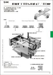
<strong>Series</strong> <strong>PAF</strong>Working Principle: Automatically Operated Type (<strong>PAF</strong>3410)Air exhaust port (AIR EXH)Switching valveAir supply port (AIR SUP)Control unitq When air is supplied, it passes through the switching valve and enters drive chamber B.w Diaphragm B moves to the right, and at the same time diaphragm A also moves to the right pushing pilot valve A.e When pilot valve A is pushed, air acts upon the switching valve, drive chamber A switches to a supply state, and the air which was indrive chamber B is exhausted to the outside.r When air enters drive chamber A, diaphragm B moves to the left pushing pilot valve B.t When pilot valve B is pushed, the air which was acting upon the switching valve is exhausted, and drive chamber B once againswitches to a supply state. A continuous reciprocal motion is generated by this repetition.Drive unitDrive unit Drive unitControl unitPilot valve APump chamber ACheck valveShaftDiaphragm A Drive chamber A Drive chamber BPilot valve BDischarge port(FLUID OUT)Pump chamber BSuction port(FLUID IN)Diaphragm Bq When air enters drive chamber B, the fluid in pump chamber B is forced out, and at the same time fluid is sucked into pump chamber A.w When the diaphragm moves in the opposite direction, the fluid in pump chamber A is forced out, and fluid is sucked into pump chamber B.e Continuous suction and discharge is performed by the reciprocal motion of the diaphragm.Working Principle: Air Operated Type (<strong>PAF</strong>3413)ExternalsolenoidvalvePump chamber A5 port solenoid valveAir supply port(AIR SUP)P1P2Discharge port(FLUID OUT)Pump chamber BCheck valveShaftDiaphragm ADrive chamber ADrive chamber BSuction port(FLUID IN)Diaphragm Bq When air is supplied to P1 port, it enters drive chamber A.w Diaphragm A moves to the left, and at the same time diaphragm B also moves to the left.e The fluid in pump chamber A is forced out to the discharge port, and the fluid is sucked into pump chamber B from the suction port.r If air is supplied to the P2 port, the opposite will occur. Continuous suction and discharge of fluid is performed by repeating this processwith the control of an external solenoid valve (5 port valve).6
Process PumpAutomatically Operated Type<strong>Series</strong> <strong>PAF</strong>Piping and Operation: Automatically Operated Type (<strong>PAF</strong>3410)Piping diagramPilot air supply portAIR SUPDischargeportFLUID OUTSilencerOptionSuction portFLUID INPilot air exhaust portAIR EXHCautionMounting orientation of the pump is set with the mounting bracket facing downward. Air to be supplied to the air supply port should be clean and filtered through a filter, or a mist separator etc. Air with foreign matter or drainage etc. will have negative effects onthe built-in solenoid valve and will lead to malfunction.Maintain the proper tightening torque for fittings and mounting bolts, etc. Looseness can cause problems such as fluid and air leaks, whileover tightening can cause damage to threads and parts, etc.Operation Refer to circuit example (1)1. Connect air piping to the air supply port and connect piping for the fluid to be transfered to the suction port and the discharge port .2. Using a regulator, set the pilot air pressure within the range of 0.2 to 0.5 MPa. Then, the pump will operate when power is applied tothe 3 port solenoid valve of the air supply port , the sound of exhaust begins from the air exhaust port and fluidwill flow from the suction port to the discharge port .At this time, the ball valve on the discharge side is in an open state. The pump performs suction with its own power even without priming.(Dry state suction lifting range: max. 1 m) To restrict exhaust noise, attach a silencer (AN200-02: option) to the air exhaust port .3. To stop the pump, exhaust the air pressure being supplied to the pump with the 3 port solenoid valve of the air supply port . The pump stops even when the ball valve on the discharge side is closed. But the pressure supply to the pump should be exhaustedquickly.1. Adjustment of the flow rate from the discharge port is performed with a ball valve connected to the discharge side or athrottle connected to the air exhaust side. For adjustment on the air side, use of a silencer with throttle ASN2 (port size 1/4) or a needlevalve connected to the air exhaust port is effective. Refer to circuit example (1).2. When operating with a discharge flow rate below the specification range, provide a by-pass circuit on the discharge side to the suctionside to ensure the minimum flow rate inside the process pump. With a discharge flow rate below the minimum flow rate, the processpump may stop due to unstable operation. Refer to circuit example (2). (Minimum flow rate: 1 l/min)When the pump stops during operation, press the reset button. This makes it possible to restore operation in case the switching valve becomesclogged due to foreign matter in the supply air.Circuit example (1)Circuit example (2)For the related products, refer topage 13.Air filterAir supply3 portsolenoid valveProcess PumpRegulatorAIR FLUIDSUP OUTAIREXHFLUIDINStrainerBall valveProcess PumpBy-passSilencerThrottleTransfer fluid7
<strong>Series</strong> <strong>PAF</strong>Piping and Operation: Air Operated Type (<strong>PAF</strong>3413)Piping diagramPilot air supply port: P1AIR SUPDischargeportFLUID OUTSuction portFLUID INPilot air supplyport: P2AIR SUPSolenoid valveRecommended Valve<strong>PAF</strong>3413Refer to page 13 for further details.VQZ140 (Exhaust centre)CautionMaintain the proper tightening torque for fittings and mounting bolts, etc. Looseness can cause problems such as fluid and air leaks, whileover tightening can cause damage to threads and parts, etc.Operation Refer to the circuit examples1. Connect air piping Note 1) to the pilot air supply port , and connect piping for the fluid to be transfered to the suction port and the discharge port .2. Using a regulator, set the pilot air pressure within the range of 0.2 to 0.5 MPa. Then, the pump will operate when power is applied to thesolenoid valve Note 2) of the pilot air supply port and fluid will flow from the suction port to the discharge port .At this time, the ball valve on the discharge side is in an open state. The pump performs suction with its own power even without priming.Note 3) (Dry state suction lifting range: Max. 1 m) To restrict exhaust noise, attach a silencer to the solenoid valve air exhaust port.3. To stop the pump, exhaust the air pressure being supplied to the pump with the solenoid valve of the air supply port.Note 1) When used for highly permeable fluids, the solenoid valve may malfunction due to the gas contained in the exhaust. Implementmeasures to keep the exhaust from going to the solenoid valve side.Note 2) For the solenoid valve, use an exhaust centre 5 port valve, or a combination of residual exhaust 3 port valve and a pump drive 4port valve. If air in the drive chamber is not released when the pump is stopped, the diaphragm will be subjected to pressure andits life will be shortened.Note 3) When the pump is dry, operate the solenoid valve at a switching cycle of 2 to 4 Hz. If operated outside of this range, the suction liftingheight may not reach the prescribed value.1. The flow rate from the discharge port can be adjusted easily by changing the switching cycle of the solenoid valve on theair supply port.Circuit example (1) Circuit example (2) For the related products, refer topage 13.Air supplyAir filter5 portsolenoid valve(Exhaust centre)RegulatorProcess PumpBall valveP1 FLUIDOUTP2 FLUIDINStrainerAir filterAir supplyRegulator3 port 4 portsolenoid solenoidvalve valveProcess PumpP1FLUIDOUTP2FLUIDINStrainer8Transfer fluidTransfer fluid
Process PumpAutomatically Operated Type<strong>Series</strong> <strong>PAF</strong>Dimensions: Automatically Operated TypeFemale thread: <strong>PAF</strong>3410- 03N03F03FLUID OUTRc, NPT, G 3/8120AIR SUPRc, NPT, G 1/416Air operatedreset portRc 1/8Tube extension: <strong>PAF</strong>3410- P13P13NP13F(ø9.50)(ø12.7)AIR SUPRc, NPT, G 1/416Air operatedreset portRc 1/81913911495141343771191069719139114951413431191067797FLUID INRc, NPT, G 3/82-M5Thread depth 963Silencer: AN200-02(Option)Reset button15213974Foot(Option)AIR EXHRc, NPT, G 1/4Bottom view of body4-ø7FLUID OUT1/2 tube extension120FLUID IN1/2 tube extension2-M5Thread depth 963Silencer: AN200-02(Option)Reset button152139110Foot(Option)AIR EXHRc, NPT, G 1/4Bottom view of body4-ø79
<strong>Series</strong> <strong>PAF</strong>Dimensions: Automatically Operated TypeWith nut (with LQ1 Fitting): <strong>PAF</strong>3410S- 1S131S19FLUID OUTWith nut120AIR SUPRc, NPT, G 1/416Air operatedreset portRc 1/819139951413431191067797FLUID INWith nutSilencer: AN200-02(Option)63AFoot(Option)AIR EXHRc, NPT, G 1/42-M5Thread depth 9Reset button1521391144-ø7Model<strong>PAF</strong>3410S-1S13<strong>PAF</strong>3410S-1S19A11511810
Process PumpAir Operated Type<strong>Series</strong> <strong>PAF</strong>Dimensions: Air Operated TypeFemale thread: <strong>PAF</strong>3413- 03N03F03FLUID OUTRc, NPT, G 3/8AIR SUP (P1)Rc, NPT, G 1/874191161149514133979119106FLUID INRc, NPT, G 3/82-M5Thread depth 959152139Foot(Option)AIR SUP (P2)Rc, NPT, G 1/8Bottom view of body4-ø7Tube extension: <strong>PAF</strong>3413- P13P13NP13FFLUID OUT1/2 tube extension(ø9.50)(ø12.7)AIR SUP (P1)Rc, NPT, G 1/81521391101911611495141339791191062-M5Thread depth 9FLUID IN1/2 tube extension59Foot(Option)AIR SUP (P2)Rc, NPT, G 1/8Bottom view of body4-ø711
<strong>Series</strong> <strong>PAF</strong>Dimensions: Air Operated TypeWith nut (with LQ1 Fitting): <strong>PAF</strong>3413S- 1S131S192-M5Thread depth 91521391413397911910619116114954-ø7FLUID OUTWith nutAIR SUP (P1)Rc, NPT, G 1/8FLUID INWith nut59AFoot(Option)AIR SUP (P2)Rc, NPT, G 1/8Model<strong>PAF</strong>3413S-1S13<strong>PAF</strong>3413S-1S19A11511812
Related ProductsRelated Products5 port solenoid valveVQZ140/240(Exhaust centre)Symbol513(R1)(P)(R2)SpecificationsModelPipingValve constructionType of actuationMax. operating pressureMin. operating pressureFlow characteristics14/2(PA/B)4/25/3(A/BEA/EB)Max. operating frequencyC[dm 3 /(s.bar)]bCvC[dm 3 /(s.bar)]bCvVQZ1420 VQZ2420 VQZ1450 VQZ2450Body portedBase mountedMetal seal3 position exhaust centre0.7 MPa (high-pressure type 1.0 MPa)0.1 MPa0.550.280.130.540.260.131.10.230.281.40.20.320.560.20.130.70.210.171.50.160.351.90.160.410 HzRefer to “Best Pneumatics” catalogue for further details.3 port solenoid valveSYJ514/714N.C.(A)21 3(P)(R)SymbolSpecificationsModelPipingValve constructionType of actuationMax. operating pressureMin. operating pressureC[dm 3 /(s.bar)]12 (PA)bCvC[dm 3 /(s.bar)]23 (AR)bCvFlow characteristicsSYJ514N.C.1.20.410.321.10.460.32Base mountedRubber seal0.7 MPa0.15 MPaSYJ714N.C.2.90.320.712.70.340.69Refer to catalogue ES11-86B for further details.Mist separator<strong>Series</strong> AMThe AM series separates and removes the oilmist in compressed air which is troublesomefor ordinary filters, and removes fine particlesof rust and carbon, etc., of 0.3 µm or larger.Should be used as the air supply for drivingthe pilot type and metal type solenoid valves.Filter regulator + Mist seperatorAir combination<strong>Series</strong> AC20D/30D/40DModelModelRated flow(l/min (ANR))Port size(Nominal size B)Weight (kg)ModelComponentdevicesPort sizeModelFilter regulatorMist seperatorPressure gauge port sizeAM150AC20DAW20AFM201/81/4AM250300 7501/8, 1/4, 3/8 1/4, 3/8, 1/20.380.55Note 1)0.15 MPa with auto drain.Note 2) When compressor discharge oil mistconcentration is 30 mg/m 3 (ANR).Refer to “Best Pneumatics” catalogue for further details.AC30DAW30AFM301/43/81/8 1/8Note 1) Conditions: Upstream pressure 0.7MPa, set pressure 0.5 MPa. The ratedflow rate varies depending onthe set pressure.Note 2) When compressor discharge concentrationis 30 mg/N·m 3 .Refer to “Best Pneumatics” catalogue for further details.SpecificationsFluidMax. operating pressureMin. operating pressure Note 1)Proof pressureAmbient and fluid temperatureNominal filtration ratingDownstream oil mistconcentrationElement service lifeSpecificationsModelProof pressureMax. operating pressureMin. operating pressureSet pressure rangeRated flow rate(l/min (ANR)) Note1)Ambient andfluid temperatureNominal filtrationratingDownstream oilmist concentrationBowl materialConstruction/Filter regulatorWeight (kg)Compressed air1.0 MPa0.05 MPa1.5 MPa5 to 60°C0.3 µm (95% filteredparticle diameter)Max. 1.0 mg/m 3Note 2)(ANR)(≈ 0.8 ppm)2 years or when thepressure drop reaches 0.1 MPa.AC20D AC30DAC40D AC40D-061.5 MPa1.0 MPa0.05 MPa0.05 to 0.85 MPa150 330 800 800–5 to 60°C (No freezing)AW: 5 µm, AFM: 0.3 µm(95% filtered particle diameter)Max. 1.0 mgf/N·m 3Note 2)(≈ 0.8 ppm)PolycarbonateRelieving type0.57 0.74 1.38 1.4313
Related ProductsRelated ProductsWater separator<strong>Series</strong> AMGThe AMG series is installed in air pressurelines to remove water droplets from compressedair. It is suitable for use in cases wherewater must be removed, but the air does nothave to be as dry as that for when an air dryeris used. It may also be used when a powersupply for an air dryer is not available, etc.ModelModel AMG150 AMG250Rated flow Note)(l /min (ANR))300 750Port size(Nominal size B)1/8, 1/4, 3/8 1/4, 3/8, 1/2Weight (kg)0.38 0.55Note) Maximum flow rate at pressure 0.7 MPaRefer to “Best Pneumatics” catalogue for further details.SpecificationsFluidCompressed airMax. operating pressure 1.0 MPaMin. operating pressure Note) 0.05 MPaProof pressure1.5 MPaAmbient and fluid temperature 5 to 60°CDehumidification rate99%2 years, or when theElement service lifepressure drop reaches 0.1 MPa.Note) 0.15 MPa with auto drain.Membrane air dryer<strong>Series</strong> IDGMacromolecular membrane dryersthat act like filtersStandard Specifications/Single Unit (Standard Dew Point –20°C)Range of operatingconditionsStandard performance conditions Standard performanceModelStandard dew point: –20°CIDG5 IDG10 IDG20 IDG30 IDG50FluidCompressed airInlet air pressure(MPa)0.3 to 0.85 0.3 to 1.0Inlet air temperature (°C) Note 1) –5 to 55–5 to 50Ambient temperature (°C)–5 to 55–5 to 50Outlet air atmosphericpressure dew point (°C)–20Inlet air flow rate(l/min (ANR))Note 2)Outlet air flow rate(l/min (ANR))Purge air flow rate(l/min (ANR))Note 3)Inlet air pressure(MPa)Inlet air temperature (°C)Inlet air saturation temperature (°C)Ambient temperature (°C)Dew point indicator purge air flow ratePort size (Nominal size B)Weight (kg)(with bracket)62 125 250 375—1/8, 1/40.25(0.31)0.72525251 l/min (ANR)1/4, 3/862550 100 200 300 50012 25 50 75 1250.43(0.51)0.66(0.76)0.74(0.87)0.77(0.90)Note 1) No freezingNote 2) ANR represents the flow rate converted to the value under 20°C at atmospheric pressure.Note 3) Including the dew point indicator purge air flow rate of 1 l/min (ANR) (inlet air pressure at 0.7 MPa)(Except for IDG5)Refer to “Best Pneumatics” catalogue for further details.Maintenance Parts List<strong>PAF</strong>3410/Automatically Operated TypeDiaphragm kit (PTFE) KT-<strong>PAF</strong>3-31Check valve kitKT-<strong>PAF</strong>3-36Switching valve parts kit KT-<strong>PAF</strong>3-37Pilot valve kitKT-<strong>PAF</strong>3-38Water leakage sensor KT-<strong>PAF</strong>3-47<strong>PAF</strong>3413/Air Operated TypeDiaphragm kit (PTFE)Check valve kitWater leakage sensorKT-<strong>PAF</strong>3-31KT-<strong>PAF</strong>3-36KT-<strong>PAF</strong>3-4714
Applicable FluidsMaterial and Fluid Compatibility Check List for Process PumpsChemicalCompatibilityAcetone Note 1, 2)Ammonium hydroxide Note 2)Isobutyl alcohol Note 1, 2)Isopropyl alcohol Note 1, 2)Hydrochloric acidOzoneHydrogen peroxideConcentration 5% or less 50°C or lessEthyl acetate Note 1, 2)Butyl acetate Note 1, 2)Nitric acidConcentration 10% or less Note 2)Pure waterSodium hydroxideConcentration 50% or lessSuper pure waterToluene Note 1, 2)Hydrofluoric acid Note 2)Sulfuric acidPhosphoric acidConcentration 80% or less Note 2)Table symbols : Can be used.: Can be used undercertain conditions.: Cannot be used.The material and fluid compatibility check list provides values for reference only.Note 1) Take measures against static electricity, since static electricity may occur.Note 2) Transmitted fluid may affect other material parts when in contacted with fluids.• Compatibility is indicated for fluid temperatures of 90°C or less.• The material and fluid compatibility check list provides values for reference only, therefore <strong>SMC</strong> does not guarantee the application to our product.• The data above is based on information provided by the material manufacturers.• <strong>SMC</strong> is not responsible for its accuracy and any damage that may happen because of this data.Back page 1
Process PumpSafety InstructionsThese safety instructions are intended to prevent a hazardous situation and/orequipment damage. These instructions indicate the level of potential hazard bylabels of "Caution", "Warning" or "Danger". To ensure safety, be sure toobserve ISO 4413 Note 1) , ISO 4414 Note 2) , JIS B 8361 Note 3) , JIS B 8370 Note 4) , JISZ 9102 Note 5) and other safety practices.CautionWarning: Operator error could result in injury or equipment damage.: Operator error could result in serious injury or loss of life.Danger: In extreme conditions, there is a possible result of serious injury or loss of life.Note 1) ISO 4413: Hydraulic fluid power – General rules for the application of equipment to transmission and contorolsystems.Note 2) ISO 4414: Pneumatic fluid power – General rules relating to systems.Note 3) JIS B 8361: General Rules for Hydraulic SystemsNote 4) JIS B 8370: General Rules for Pneumatic EquipmentNote 5) JIS Z 9102: Piping identification markingsWarning1. The compatibility of the equipment is the responsibility of the person whodesigns the system or decides its specifications.Since the products specified here are used in various operating conditions, their compatibility for thespecific system must be based on specifications or post analysis and/or tests to meet the specificrequirements. The expected performance and safety assurance are the responsibility of the personwho has determined the compatibility of the system. This person should continuously review thesuitability of all items specified, referring to the latest catalogue information with a view to giving dueconsideration to any possibility of equipment failure when configuring a system. Be particularly carefulin determining the compatibility with the fluid to be used.2. Only trained personnel should operate machinery and equipment.The fluid can be dangerous if handled incorrectly. Assembly, handling or repair of the systems shouldbe performed by trained and experienced operators.3. Do not service machinery/equipment or attempt to remove components untilthe safety is confirmed.1. Inspection and maintenance of machinery/equipment should only be performed once measures toprevent falling or runaway of the driven objects have been confirmed. Measures to prevent dangerfrom a fluid should also be confirmed.2. When equipment is removed, confirm the safety process as mentioned above. Release the fluidpressure and be certain there is no danger from fluid leakage or fluid remaining in the system.3. Carefully restart the machinery, confirming that safety measures are being implemented.4. Do not use the product if it will use in an of the following conditions:1. Conditions or environments beyond the specifications given in the catalogue and instruction manual.2. With fluids whose application causes concern due to the type of fluid or additives, etc.3. Installation on equipment in conjunction with atomic energy, railway, air navigation, vehicles,medical equipment, food and beverages, recreation equipment, emergency stop circuits, clutch andbrake circuits in press applications, or safety equipment.4. An application which has the possibility of having negative effects on people, property, requiringspecial safety analysis.Back page 2
Process Pump Precautions 1Be sure to read this before handling.Refer to the main catalogue sections for detailed precautions on each series.Caution on DesignWarning1. Check the specifications.Give careful consideration to operating conditions such asthe application, fluid and environment, and use within theoperating ranges specified in this catalogue.2. FluidRegarding the component parts material and the fluid compatibility,check the applicable fluid check list (see back page 1)prior to use. Please consult with <strong>SMC</strong> for fluids other thanthose on the check list. Also, please use within the operatingfluid temperature range.3. Maintenance spaceThe installation should allow sufficient space for maintenanceactivities. Use the product, considering that liquid may leakfrom the product.4. Fluid pressureDo not apply pressure to the operating fluid.5. Ambient environmentOperate within the ambient operating temperature range. Afterconfirming the compatibility of the product’s componentmaterials with the ambient environment, operate so that fluiddoes not adhere to the product’s exterior surfaces.6. Liquid ringsIn cases with a flowing liquid, provide a by-pass valve in thesystem to prevent the liquid from entering the liquid seal circuit.7. Measures against static electricityTake measures against static electricity as static electricitymay occur depending on a fluid.8. Suspension of the pump operationFor the automatic operation type, use a 3-port solenoid valvewhen the process pump is started or stopped by the pilot air.If the pump should stop while consuming the residual pressure,the integral switch part of the pilot air may not be stabilisedor cannot be restarted. If it should not restart, press thereset button.9. Cannot be used for gaseous transfer.When used for gaseous transfer, sufficient transfer volumecannot be gained due to the nature of compression. Besides,as the operational cycle is too fast, unexpected malfuctionsmay occur within short periods of time.10. Use the constant pilot air pressure.The pump may malfunction and stop when the pilot air pressurefluctuation exceeds 50 kPa because the automaticallyoperated type adopts an air spring for the in-built air controlcircuit.11. Use a design which prevents reverse pressure andreverse flow.If reverse pressure or flow occurs, this can cause equipmentdamage or malfunction, etc. Take measures in designing thecircuit diagram.Warning12. Condensation and freezing of the pilot portFor the automatically operated type, the location around theswitching valve and the air exhaust part can cool down quicklydue to expansion of the supply air, this may cause the pipesto freeze. Take measures to ensure that water droplets arenot splashed onto any electric parts or equipment.CautionMounting1. The sealed package should only be opened inside aclean room.This product is double packed inside a clean room. We recommendthat the inner package should be opened inside aclean room or clean environment.2. Confirm the mounting orientation of the product.Mount the product, with its bottom surface facing downwards.Fix all the mounting locations prior to use.CautionPiping1. Flush the pipes.Connect the product after flushing and washing the pipes. Ifany foreign matter is left in the pipes, malfunction or failuremay occur.2. Use the fittings with a resin thread when piping tothe pilot port.Using fittings with metal threads may result in damage to thepilot port.3. Always tighten threads with the proper tighteningtorque.When screwing fittings into valves, tighten with the propertightening torque shown below.Connection threadRc, NPT, G 1/8Rc, NPT, G 1/4Rc, NPT, G 3/8Proper tightening torque (Nm)0.4 to 0.50.8 to 12 to 2.5Back page 3
Process Pump Precautions 2Be sure to read this before handling.Refer to the main catalogue sections for detailed precautions on each series.WarningWarningOperating Environment1. Do not use in the following environments, as thiscan cause failure.1) Locations with an atmosphere of corrosive gases, organicsolvents or chemical solutions, and where there may becontact with the same.2) Locations where there is contact with sea spray, water orsteam.3) Locations where there is contact with direct sunlight. (Sunlightshould be blocked to prevent deterioration of resinfrom ultra violet rays and over heating, etc.)4) Locations near heat sources with poor ventilation. (Heatsources should be shielded.)5) Locations with impact or vibration.6) Locations with high moisture and dust.2. Do not use the product under water.Do not use the product under water. Otherwise, liquid will enterthe inside of the product, resulting in malfunction.WarningAir Supply1. Use clean air.If the compressed air includes synthetic oil containing chemicals,organic solvents, salt, corrosive gas, etc., this may causedamage to the product resulting in malfunction.2. Quality of operating airBe sure to use only air filtrated by a mist separator (<strong>SMC</strong>’sAM <strong>Series</strong>). However, if you would like to extend the productsservice life, we would recommend using our super mist separator– AME <strong>Series</strong>.3. When operating this product in low temperatures,please pay special attention to avoid freezing.Compressed air is expanded while the equipment operates.During this, the temperature inside the product decreases dueto adiabatic expansion. This will cause freezing if compressedair with a high moisture content is used. In this case, takefreeze prevention measures by using a membrane air dryer.(<strong>SMC</strong>’s IDG <strong>Series</strong>)Maintenance1. Only undertake maintenance after consulting theinstruction manual.When undertaking maintenance, you should refer to theequipment’s instruction manual supplied by <strong>SMC</strong> or our Distributor.Incorrect handling may cause damage to the productresulting in malfunction.WarningCaution on Design2. Only undertake maintenance once the system hasbeen confirmed as safe.Turn off the compressed air and the power supply voltage andexhaust any remaining compressed air in the pipes before removingor attaching the equipment or removing the compressedair supply / exhaust equipment. Exhaust any residual liquidas considered necessary. Also, when the equipment ismounted again or restarted after replacement, check that it’ssafe and then confirm that the product runs normally.3. Do not disassemble the product, as disassemblywill invalidate the product's warranty.When disassembly is necessary, please consult with <strong>SMC</strong> orour Distributor.4. Drain dischargeIf drain accumulates in equipment, in piping or other areas,this can cause malfunction of the equipment or unexpectedtrouble due to splash over into the downstream side, etc. Exhaustthe drain from air filter, etc. periodically.5. Caution when transferring a high-temperature fluidThis product will become hot due to its high-temperature operation.Touching the product directly may cause burns. Beforetransferring a high-temperature fluid, please allow sufficient timefor the fluid to cool slightly. We also recommend that thesystem is safe prior to fluid transfer by detecting the product’stemperature.6. Caution when a thermal heat cycle is applied.When a heat cycle is applied, the resin thread may extend.Additionally tighten with the specified torque (M3: 0.11 to 0.12Nm) to prevent liquid leakage.Caution1. Caution for transferring a highly permeable liquidCompared with the fluororesin, when a highly permeable liquidis transferred, an ingredient of the transfer liquid may ingressinto the openings inside the equipment. Additionally, it may becomeattached to the external surface on the equipment. In thiscase, take the same measures as handling the transfer liquid.2. Service lifeWhen the process pump exceeds the diaphragm service life,the diaphragm may become degraded or damaged. Furthermore,the internal pilot air circuit will not be able to work, makingoperation impossible. We recommend that the diaphragm bereplaced before its service life has expired.Service life days = 41,000 per daily operation time (time) / flow(l/ min)WarningCaution on Handling1. If unused for long periods of time, perform a trialrun prior to operation.Back page 4
© DiskArt 1988EUROPEAN SUBSIDIARIES:Austria<strong>SMC</strong> Pneumatik GmbH (Austria).Girakstrasse 8, A-2100 KorneuburgPhone: +43 2262-62280, Fax: +43 2262-62285E-mail: office@smc.athttp://www.smc.atFrance<strong>SMC</strong> Pneumatique, S.A.1, Boulevard de Strasbourg, Parc Gustave EiffelBussy Saint Georges F-77607 Marne La Vallee Cedex 3Phone: +33 (0)1-6476 1000, Fax: +33 (0)1-6476 1010E-mail: contact@smc-france.frhttp://www.smc-france.frNetherlands<strong>SMC</strong> Pneumatics BVDe Ruyterkade 120, NL-1011 AB AmsterdamPhone: +31 (0)20-5318888, Fax: +31 (0)20-5318880E-mail: info@smcpneumatics.nlhttp://www.smcpneumatics.nlSpain<strong>SMC</strong> España, S.A.Zuazobidea 14, 01015 VitoriaPhone: +34 945-184 100, Fax: +34 945-184 124E-mail: post@smc.smces.eshttp://www.smces.esBelgium<strong>SMC</strong> Pneumatics N.V./S.A.Nijverheidsstraat 20, B-2160 WommelgemPhone: +32 (0)3-355-1464, Fax: +32 (0)3-355-1466E-mail: post@smcpneumatics.behttp://www.smcpneumatics.beGermany<strong>SMC</strong> Pneumatik GmbHBoschring 13-15, D-63329 EgelsbachPhone: +49 (0)6103-4020, Fax: +49 (0)6103-402139E-mail: info@smc-pneumatik.dehttp://www.smc-pneumatik.deNorway<strong>SMC</strong> Pneumatics Norway A/SVollsveien 13 C, Granfos Næringspark N-1366 LysakerTel: +47 67 12 90 20, Fax: +47 67 12 90 21E-mail: post@smc-norge.nohttp://www.smc-norge.noSweden<strong>SMC</strong> Pneumatics Sweden ABEkhagsvägen 29-31, S-141 71 HuddingePhone: +46 (0)8-603 12 00, Fax: +46 (0)8-603 12 90E-mail: post@smcpneumatics.sehttp://www.smc.nuBulgaria<strong>SMC</strong> Industrial Automation Bulgaria EOOD16 kliment Ohridski Blvd., fl.13 BG-1756 SofiaPhone:+359 2 9744492, Fax:+359 2 9744519E-mail: office@smc.bghttp://www.smc.bgGreeceS. Parianopoulus S.A.7, Konstantinoupoleos Street, GR-11855 AthensPhone: +30 (0)1-3426076, Fax: +30 (0)1-3455578E-mail: parianos@hol.grhttp://www.smceu.comPoland<strong>SMC</strong> Industrial Automation Polska Sp.z.o.o.ul. Konstruktorska 11A, PL-02-673 Warszawa,Phone: +48 22 548 5085, Fax: +48 22 548 5087E-mail: office@smc.plhttp://www.smc.plSwitzerland<strong>SMC</strong> Pneumatik AGDorfstrasse 7, CH-8484 WeisslingenPhone: +41 (0)52-396-3131, Fax: +41 (0)52-396-3191E-mail: info@smc.chhttp://www.smc.chCroatia<strong>SMC</strong> Industrijska automatika d.o.o.Crnomerec 12, 10000 ZAGREBPhone: +385 1 377 66 74, Fax: +385 1 377 66 74E-mail: office@smc.hrhttp://www.smceu.comHungary<strong>SMC</strong> Hungary Ipari Automatizálási Kft.Budafoki ut 107-113, H-1117 BudapestPhone: +36 1 371 1343, Fax: +36 1 371 1344E-mail: office@smc-automation.huhttp://www.smc-automation.huPortugal<strong>SMC</strong> Sucursal Portugal, S.A.Rua de Engº Ferreira Dias 452, 4100-246 PortoPhone: +351 22-610-89-22, Fax: +351 22-610-89-36E-mail: postpt@smc.smces.eshttp://www.smces.esTurkeyEntek Pnömatik San. ve Tic Ltd. Sti.Perpa Tic. Merkezi Kat: 11 No: 1625, TR-80270 Okmeydani IstanbulPhone: +90 (0)212-221-1512, Fax: +90 (0)212-221-1519E-mail: smc-entek@entek.com.trhttp://www.entek.com.trCzech Republic<strong>SMC</strong> Industrial Automation CZ s.r.o.Hudcova 78a, CZ-61200 BrnoPhone: +420 5 414 24611, Fax: +420 5 412 18034E-mail: office@smc.czhttp://www.smc.czIreland<strong>SMC</strong> Pneumatics (Ireland) Ltd.2002 Citywest Business Campus, Naas Road, Saggart, Co. DublinPhone: +353 (0)1-403 9000, Fax: +353 (0)1-464-0500E-mail: sales@smcpneumatics.iehttp://www.smcpneumatics.ie© DiskArtRomaniaUK<strong>SMC</strong> Romania srl<strong>SMC</strong> Pneumatics (UK) LtdStr Frunzei 29, Sector 2, BucharestVincent Avenue, Crownhill, Milton Keynes, MK8 0ANPhone: +40 213205111, Fax: +40 213261489 Phone: +44 (0)800 1382930 Fax: +44 (0)1908-555064E-mail: smcromania@smcromania.ro E-mail: sales@smcpneumatics.co.ukhttp://www.smcromania.rohttp://www.smcpneumatics.co.ukDenmark<strong>SMC</strong> Pneumatik A/SKnudsminde 4B, DK-8300 OdderPhone: +45 70252900, Fax: +45 70252901E-mail: smc@smc-pneumatik.dkhttp://www.smcdk.comItaly<strong>SMC</strong> Italia S.p.AVia Garibaldi 62, I-20061Carugate, (Milano)Phone: +39 (0)2-92711, Fax: +39 (0)2-9271365E-mail: mailbox@smcitalia.ithttp://www.smcitalia.itRussia<strong>SMC</strong> Pneumatik LLC.4B Sverdlovskaja nab, St. Petersburg 195009Phone.:+812 718 5445, Fax:+812 718 5449E-mail: info@smc-pneumatik.ruhttp://www.smc-pneumatik.ruEstonia<strong>SMC</strong> Pneumatics Estonia OÜLaki 12-101, 106 21 TallinnPhone: +372 (0)6 593540, Fax: +372 (0)6 593541E-mail: smc@smcpneumatics.eehttp://www.smcpneumatics.eeLatvia<strong>SMC</strong> Pneumatics Latvia SIASmerla 1-705, Riga LV-1006, LatviaPhone: +371 781-77-00, Fax: +371 781-77-01E-mail: info@smclv.lvhttp://www.smclv.lvSlovakia<strong>SMC</strong> Priemyselná Automatizáciá, s.r.o.Námestie Martina Benku 10, SK-81107 BratislavaPhone: +421 2 444 56725, Fax: +421 2 444 56028E-mail: office@smc.skhttp://www.smc.skFinland<strong>SMC</strong> Pneumatics Finland OYPL72, Tiistinniityntie 4, SF-02031 ESPOOPhone: +358 207 513513, Fax: +358 207 513595E-mail: smcfi@smc.fihttp://www.smc.fiLithuania<strong>SMC</strong> Pneumatics Lietuva, UABSavanoriu pr. 180, LT-01354 Vilnius, LithuaniaPhone: +370 5 264 81 26, Fax: +370 5 264 81 26Slovenia<strong>SMC</strong> industrijska Avtomatika d.o.o.Grajski trg 15, SLO-8360 ZuzemberkPhone: +386 738 85240 Fax: +386 738 85249E-mail: office@smc-ind-avtom.sihttp://www.smc-ind-avtom.siOTHER SUBSIDIARIES WORLDWIDE:ARGENTINA, AUSTRALIA, BOLIVIA, BRASIL, CANADA, CHILE,CHINA, HONG KONG, INDIA, INDONESIA, MALAYSIA, MEXICO,NEW ZEALAND, PHILIPPINES, SINGAPORE, SOUTH KOREA,TAIWAN, THAILAND, USA, VENEZUELAhttp://www.smceu.comhttp://www.smcworld.com<strong>SMC</strong> CORPORATION Akihabara UDX 15F, 4-14-1, Sotokanda, Chiyoda-ku, Tokyo 101-0021, JAPAN Phone: 03-5207-8249 FAX: 03-5298-53621st printing KQ printing KQ 00 UK Printed in SpainSpecifications are subject to change without prior noticeand any obligation on the part of the manufacturer.