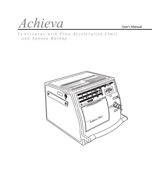
Achieva - Covidien
Achieva - Covidien
Achieva - Covidien

You also want an ePaper? Increase the reach of your titles
YUMPU automatically turns print PDFs into web optimized ePapers that Google loves.
Nellcor Puritan Bennett Inc. is an affiliate of Tyco Healthcare. <strong>Achieva</strong>® and Puritan Bennett® areregistered trademarks of Nellcor Puritan Bennett Incorporated. © 2007 Nellcor Puritan Bennett Corporation.All rights reserved.For further information, contact your Puritan Bennett representative, or contact Nellcor Puritan Bennettdirectly by calling 1-800-635-5267.
SECTIONCONTENTS1 Safety Information 1-11.1 Definitions...................................................................................................................1-11.2 Warnings and Cautions ...............................................................................................1-12 Overview 2-12.1 Intended Use...............................................................................................................2-12.2 Role of Your Clinician ..................................................................................................2-12.3 How the Ventilator Works............................................................................................2-12.3.1 Overview of Ventilation .....................................................................................2-12.3.2 Important Terms................................................................................................2-12.3.3 Modes of Ventilation .........................................................................................2-22.3.3.1 Assist/Control (A/C) Mode...........................................................................2-22.3.3.2 SIMV Mode .................................................................................................2-22.3.3.3 Spontaneous (SPON) Mode.........................................................................2-23 Description 3-13.1 Model Number............................................................................................................3-13.2 Symbols ......................................................................................................................3-13.3 Front Panel..................................................................................................................3-43.3.1 Top Panel ..........................................................................................................3-53.3.2 Door Panel ........................................................................................................3-63.4 Rear and Side Panels....................................................................................................3-93.5 Power Supply ..............................................................................................................3-93.5.1 AC Power ........................................................................................................3-103.5.2 External Battery ...............................................................................................3-103.5.3 Internal Battery................................................................................................3-103.6 Patient Circuit............................................................................................................3-113.7 Supplemental Oxygen...............................................................................................3-123.7.1 Oxygen Enrichment Kit....................................................................................3-123.7.2 90° Elbow with Oxygen Fitting ........................................................................3-133.8 Humidification Devices ..............................................................................................3-134 Set Up 4-14.1 Preparing the Ventilator...............................................................................................4-14.2 Where to Place the Ventilator ......................................................................................4-24.2.1 Electrical Interference.........................................................................................4-34.3 Mounting the Ventilator on a Wheelchair ....................................................................4-34.4 Connecting the Patient Circuit ....................................................................................4-44.5 Connecting the Ventilator to an AC Power Outlet........................................................4-54.6 Using an External Battery.............................................................................................4-64.7 Setting the Low Pressure Alarm ...................................................................................4-74.8 Configuring for Assist/Control Ventilation....................................................................4-8iii
Contents5 Test 5-15.1 Completing the User Self Test ..................................................................................... 5-15.2 Testing the Ventilator’s Alarms .................................................................................... 5-35.2.1 Low Pressure Test.............................................................................................. 5-35.2.2 Apnoea Test ...................................................................................................... 5-45.2.3 Power Failure Test ............................................................................................. 5-45.2.4 Continuing Pressure (Valley) Test ...................................................................... 5-55.2.5 High Pressure Test............................................................................................. 5-55.3 Testing the Battery...................................................................................................... 5-65.4 Monthly Safety Check ................................................................................................. 5-66 Operation 6-16.1 Turning on the Ventilator............................................................................................ 6-16.2 Displaying Settings...................................................................................................... 6-16.3 Setting Parameters...................................................................................................... 6-16.4 Starting Ventilation ..................................................................................................... 6-26.5 Stopping Ventilation ................................................................................................... 6-27 Alarms and Alerts 7-17.1 Alarm/Alert Conditions................................................................................................ 7-17.2 Resetting Alarms ......................................................................................................... 7-47.3 Alarm Latching............................................................................................................ 7-47.4 Pre-Silencing Audible Alarms....................................................................................... 7-58 Cleaning and Maintenance 8-18.1 Cleaning the Ventilator ............................................................................................... 8-18.2 Cleaning the Accessories ............................................................................................. 8-18.3 Recharging the Internal Battery................................................................................... 8-28.4 Cycling Internal and External Batteries ........................................................................ 8-28.4.1 External Battery................................................................................................. 8-28.4.2 Internal Battery ................................................................................................. 8-28.5 Home Maintenance .................................................................................................... 8-28.5.1 Replacing the Air Inlet Filter............................................................................... 8-28.5.2 Changing the Ventilator’s Fuses ........................................................................ 8-38.6 Preventive Maintenance.............................................................................................. 8-59 Technical Reference 9-19.1 Introduction................................................................................................................ 9-19.2 Ventilator Specifications .............................................................................................. 9-19.3 Alarm Conditions ....................................................................................................... 9-69.4 Troubleshooting........................................................................................................ 9-1410 Warranty Information 10-110.1 Limited Warranty .................................................................................................... 10-1IndexIndex-1iv
SECTIONFIGURESFigure 3-1. Front Panel. . . . . . . . . . . . . . . . . . . . . . . . . . . . . . . . . . . . . . . . . . . . . . . . . . . . . . . . . . . . . . 3-4Figure 3-2. Top Panel. . . . . . . . . . . . . . . . . . . . . . . . . . . . . . . . . . . . . . . . . . . . . . . . . . . . . . . . . . . . . . . 3-5Figure 3-3. Door Panel General Controls . . . . . . . . . . . . . . . . . . . . . . . . . . . . . . . . . . . . . . . . . . . . . . . . 3-7Figure 3-4. Door Panel Setting Controls and Display . . . . . . . . . . . . . . . . . . . . . . . . . . . . . . . . . . . . . . . 3-8Figure 3-5. Rear and Side Panels . . . . . . . . . . . . . . . . . . . . . . . . . . . . . . . . . . . . . . . . . . . . . . . . . . . . . . 3-9Figure 3-6. Patient Circuit . . . . . . . . . . . . . . . . . . . . . . . . . . . . . . . . . . . . . . . . . . . . . . . . . . . . . . . . . . 3-11Figure 3-7. Connecting the Oxygen Supply . . . . . . . . . . . . . . . . . . . . . . . . . . . . . . . . . . . . . . . . . . . . . 3-12Figure 3-8. <strong>Achieva</strong> Ventilator Connected to a Humidifier . . . . . . . . . . . . . . . . . . . . . . . . . . . . . . . . . . 3-14Figure 4-1. Ventilator and Battery Placement on Wheelchair . . . . . . . . . . . . . . . . . . . . . . . . . . . . . . . . . 4-4Figure 4-2. Connecting the Power Cord to the Ventilator. . . . . . . . . . . . . . . . . . . . . . . . . . . . . . . . . . . . 4-5Figure 4-3. Connecting the Power Cord to an AC Outlet . . . . . . . . . . . . . . . . . . . . . . . . . . . . . . . . . . . . 4-6Figure 5-1. Blocking the Exhalation Manifold . . . . . . . . . . . . . . . . . . . . . . . . . . . . . . . . . . . . . . . . . . . . . 5-2Figure 8-1. Air Inlet Filter Assembly . . . . . . . . . . . . . . . . . . . . . . . . . . . . . . . . . . . . . . . . . . . . . . . . . . . . 8-3Figure 8-2. Removing the Fuse Holder . . . . . . . . . . . . . . . . . . . . . . . . . . . . . . . . . . . . . . . . . . . . . . . . . . 8-4Figure 8-3. Fuse Assembly . . . . . . . . . . . . . . . . . . . . . . . . . . . . . . . . . . . . . . . . . . . . . . . . . . . . . . . . . . . 8-4v
SECTIONTABLESTable 3-1: Symbols . . . . . . . . . . . . . . . . . . . . . . . . . . . . . . . . . . . . . . . . . . . . . . . . . . . . . . . . . . . . . . . . 3-1Table 5-2: User Self Test Results . . . . . . . . . . . . . . . . . . . . . . . . . . . . . . . . . . . . . . . . . . . . . . . . . . . . . . 5-2Table 7-1: Alarm and Alert Conditions . . . . . . . . . . . . . . . . . . . . . . . . . . . . . . . . . . . . . . . . . . . . . . . . . 7-2vii
This page intentionally blank
SECTIONCHAPTERSafety Information 111.1 DefinitionsThis manual uses three indicators to highlight information of particular importance. They are:WarningIndicates a condition that can endanger the patient or the ventilator operator.CautionIndicates a condition that can damage the equipment.NOTE:Indicates points of particular emphasis that make operation of the ventilator more efficientor convenient.1.2 Warnings and CautionsThis section lists general warnings and cautions for your safety and that of the patient.WarningsWarning• Read all of this manual before using the ventilator.• Anything that damages the ventilator may cause danger to the patient.• Do not use your ventilator until you have been properly trained by your clinician and haveread and understand this manual.• Make sure you can hear the ventilator’s alarm from other areas of the house, and whenyou are using appliances such as a vacuum cleaner, dishwasher, clothes dryer, television,or radio.• Do not use the ventilator if you suspect it may not be working properly. Contact yourclinician to have the ventilator tested or replaced.• If the patient’s condition warrants the use of an independent secondary alarm or a backupmeans of ventilation, the clinician should prescribe it.• Wash your hands thoroughly before and after handling patient connectors and otheraccessories.• Always check the ventilator’s breath delivery settings before using the ventilator with apatient. When adjusting settings, special care should be taken to ensure that the newsettings are correct. The use of incorrect settings during ventilation can endanger thepatient.<strong>Achieva</strong> Ventilator User’s Manual1-1
1 Safety InformationWarning• To avoid a fire hazard, keep matches, lighted cigarettes, and all other sources of ignition(such as flammable anesthetics and/or heaters) away from the <strong>Achieva</strong> ventilator systemand oxygen hoses.• Do not use hoses that are worn, frayed, or contaminated by combustible materials suchas grease or oils.• In case of a burning smell, immediately disconnect the ventilator from the oxygen supply,AC power, and backup power source.• All alarms indicate a potential risk to patient safety. When an alarm sounds, provideimmediate attention, care, and support to the patient as dictated by the situation.• Any device is subject to unpredictable failures. To ensure patient safety, an appropriatelytrained caregiver should monitor ventilation.• If the patient’s condition warrants the use of an independent secondary alarm, remotealarm, or another external monitoring device, the physician should prescribe it. Thephysician should also determine if the patient requires an alternate means of ventilation.• Certain types of ventilators, including the <strong>Achieva</strong> Series, have a Low Inspiratory PressureAlarm. The purpose of this alarm is to alert the clinician or caregiver when the pre-setalarm parameters are violated. As set forth in the <strong>Achieva</strong> Series Clinician’s and User’sManuals, a number of environmental factors and circuit accessories/components canaffect the pressure in the breathing circuit. These factors may prevent circuit pressurefrom violating the low-pressure parameters, even in the event of a circuit beingdisconnected from the patient. Therefore, it is important for the clinician to consider andmonitor these environmental factors when establishing pressure alarm parameters.Depending on the specific clinical situation (such as when the risk of disconnect isperceived as high and the patient is ventilator-dependent), a secondary means ofmonitoring ventilation, such as pulse oximetry, should be considered.CautionsCaution• Do not attempt to make any repairs or otherwise service the ventilator. Contact anauthorized service representative for any service needs.• Do not use or store this ventilator in the presence of strong electromagnetic fields, suchas an MRI environment.1-2 <strong>Achieva</strong> Ventilator User’s Manual
SECTIONCHAPTEROverview 222.1 Intended UseThis device is intended to provide ventilatory support for pediatric and adult patients who requirepositive pressure mechanical ventilation. Patients should weight no less than 11 lbs (5 kg).Thisdevice is for use in home, institutional, and portable settings.This device is contraindicated for use with anesthetic gases. This device is intended to be used onthe order, and under the supervision, of a physician.2.2 Role of Your ClinicianIn this manual, the term clinician means the trained health-care professional who is helping you usethe <strong>Achieva</strong> ventilator in your home. This may be a doctor or nurse who is treating your patient, orsome other trained health-care professional.Your clinician will:• Order a ventilator for use in your home• Train you to use the ventilator• Help you to set up the ventilator• Select appropriate accessories to use with your ventilator• Show you how to respond to alarms• Answer your questions about using the ventilator• Follow up with you on a regular basis to make sure the ventilator is meeting your needs2.3 How the Ventilator Works2.3.1 Overview of VentilationA ventilator - like the <strong>Achieva</strong> ventilator you are about to use - is a device that is designed to assistthe patient by moving air into their lungs and providing adequate ventilation.2.3.2 Important TermsYou should be aware of the following terms that will appear frequently throughout this manual.Mode: The manner or method of ventilatory support provided by the ventilator.Volume: The amount of air delivered to the patient with each breath.Pressure: A measure of the pressure required to “push” air into the patient’s lungs.Respiratory Rate: The number of breaths per minute.<strong>Achieva</strong> Ventilator User’s Manual2-1
2 Overview2.3.3 Modes of VentilationThe following is a general description of the various modes of ventilation available with the<strong>Achieva</strong> ventilator. It is up to your clinician to determine which modes are appropriate for yourpatient.2.3.3.1 Assist/Control (A/C) ModeIn Assist/Control mode, machine-initiated breaths are delivered at a clinician-set volume orpressure, inspiratory time, and rate. If the patient triggers a spontaneous breath between machinebreaths, the ventilator will deliver a breath based on the volume or pressure settings. Whetherinitiated by the patient or the ventilator, all breaths are delivered at the same pre-set volume orpressure.2.3.3.2 SIMV ModeIn SIMV (Synchronized Intermittent Mandatory Ventilation) Mode, machine-initiated breaths aredelivered at a clinician-set volume, inspiratory time and rate. These mandatory breaths aresynchronized with patient effort. If the patient triggers a spontaneous breath between machinebreaths, the ventilator will deliver a spontaneous breath, which can be pressure-supported.Spontaneous breaths in SIMV do not have a pre-set volume or pressure.2.3.3.3 Spontaneous (SPON) ModeIn Spontaneous mode, breaths are delivered with a volume, pressure and rate that are determinedby the patient. Spontaneous mode is most frequently used with either CPAP (Continuous PositiveAirway Pressure) or a combination of PS (Pressure Support) +CPAP.2.3.3.3.1 CPAPIn CPAP, the ventilator maintains a constant level of pressure in the patient’s airway. This can helpto improve oxygenation, or the level of oxygen in the patient’s blood. If your clinician hasprescribed CPAP, you should talk to him or her for a further explanation of how CPAP works.2.3.3.3.2 PS+CPAPLike CPAP, PS+CPAP maintains a constant level of pressure in the patient’s airway. In addition, theventilator applies a clinician-set pressure to each of the patient’s breaths. This has the same benefitsas CPAP, with the additional benefit of assisting the patient in moving air into the lungs.2-2 <strong>Achieva</strong> Ventilator User’s Manual
SECTIONCHAPTERDescription 333.1 Model Number3.2 SymbolsThe <strong>Achieva</strong>’s model number is printed on the front door panel. There are certain featuresdescribed in this manual that only pertain to certain models.Table 3-1 lists the symbols that are used on the <strong>Achieva</strong> system.Table 3-1: SymbolsSymbolDescriptionRegulatoryCE mark: This device complies with the requirements ofDirective 93/42/EEC concerning medical devices.Type BF equipment, degree of protection against electricalshockClassified by Underwriters Laboratories Inc. with respect toelectric shock, fire and mechanical hazards only in accordancewith UL2601-1Certified by Canadian Standards Association to meet CAN/CSAC22.2 No. 601.1-M90Caution/Warning/SafetyAttention, consult accompanying manualKeep dryFragileAlarm IndicatorsAlarm indicatorLow Pressure/Apnoea LED alarm indicatorHigh Pressure LED alarm indicatorSetting Error LED alarm indicator<strong>Achieva</strong> Ventilator User’s Manual3-1
3 DescriptionTable 3-1: Symbols (continued)SymbolDescriptionPower Switch-Over LED alarm indicatorLow Power LED alarm indicatorO 2 Fail LED alarm indicatorAlarm Control LED indicatorPower IndicatorsAC (alternating current) LED power source indicatorExternal Battery LED power source indicatorInternal Battery LED power source indicatorBattery Charging LED indicatorElectricalAlternating currentDirect currentVoltsAmperesKeysStandby mode of operationAlarm Silence/Reset keyTest Battery keyMode selection keyMenu/Escape function selection key3-2 <strong>Achieva</strong> Ventilator User’s Manual
Description 3Table 3-1: Symbols (continued)SymbolDescriptionUp Arrow keyDown Arrow keyVolume parameter setting keyInspiratory Time parameter setting keyBreath Rate parameter setting keyPressure Support parameter setting keyPositive End Expiratory Pressure parameter setting keyLow Pressure alarm setting keyHigh Pressure alarm setting keySensitivity parameter setting keyF l O 2 (oxygen) parameter setting keyStart/Enter function setting keyVentilate function setting keyDisplaysI/E Ratio LCDFlow LCDLabels and ConnectorsDrip proofExternal Battery power connector<strong>Achieva</strong> Ventilator User’s Manual 3-3
3 DescriptionTable 3-1: Symbols (continued)SymbolDescriptionMiscellaneous IndicatorsAssist/Spontaneous LED indicator3.3 Front PanelFigure 3-1. Front PanelADEBCFGA. Top PanelB. Liquid Crystal Display (LCD)C. Door Panel (open to reveal Display and Controls)D. Patient Pressure MeterE. Exhalation Valve PortF. Patient Air PortG. Patient Pressure Port3-4 <strong>Achieva</strong> Ventilator User’s Manual
Description 33.3.1 Top PanelFigure 3-2. Top PanelGABFECDA. Alarms IndicatorsB. Power IndicatorsC. Alarm Control IndicatorD. Assist/Spontaneous IndicatorE. Patient Pressure MeterF. Alarm Silence/Reset KeyG. Test Battery KeyA. Alarms IndicatorsThe ventilator’s Alarms Indicators will flash when an alarm condition is detected. Theindicators are turned off only when the condition is corrected, and the ALARM SILENCE/RESETkey is pressed. Alarms Indicators exist for the following alarm conditions:– Low Pressure/Apnoea– High Pressure– Setting Error– Power Switch-Over– Low Power– O 2 Fail (<strong>Achieva</strong> PSO 2 only)These alarm conditions will be explained later in this manual. For now, be sure to familiarizeyourself with the location of the Alarms Indicators.NOTE:For the <strong>Achieva</strong> and <strong>Achieva</strong> PS models that do not have the oxygen function, theO 2 FAIL alarm indicator position is present; however, the position is empty and unlabeled.<strong>Achieva</strong> Ventilator User’s Manual 3-5
3 DescriptionB. Power IndicatorsThe ventilator’s Power Indicators show which electrical source the ventilator is currently usingand if the internal battery is being charged. Power Indicators exist for the following powerconditions:– AC– External Battery– Internal Battery– Battery ChargingThese power conditions will be explained later in this manual. For now, be sure to familiarizeyourself with the location of the Power Indicators.C. Alarm Control IndicatorThe ALARM CONTROL indicator flashes when the audible alarm has been presilenced, but is litcontinuously when the nonlatching alarm feature is active. You will learn more about presilencingalarms later in this manual.D. Assist/Spontaneous IndicatorThe ASSIST/SPONTANEOUS indicator lights when the patient’s breathing effort meets or exceedsthe ventilator’s sensitivity setting.E. Patient Pressure MeterThe PATIENT PRESSURE meter (Figure 3-2, item “E”) shows the level of pressure that is currentlyin the patient circuit.F. Alarm Silence/Reset KeyThe ALARM SILENCE/RESET key silences the audible alarm during an alarm condition and can beused to pre-silence the audible alarm for a period of 60 seconds. If an alarm condition occurswhile the 60-second pre-silence period is in effect or while ALARM SILENCE/RESET is active, thefront panel LCD (Figure 3-1, item “B”) will display the alarm condition, but the alarm will notsound. This key can also be used to reset an alarm after the alarm condition has been corrected.G. Test Battery KeyWhen the TEST BATTERY key is pressed and held, the PATIENT PRESSURE meter (Figure 3-2, item“E”) shows the charge level of the battery currently in use.3.3.2 Door PanelThe display and control panel is located behind the ventilator’s front door panel (Figure 3-3). Thisfront door panel is magnetically latched to prevent tampering and accidental resetting when closed.The following is a brief explanation of each of the controls. Further information regarding how andwhen you should use the controls will be provided later in this manual.3-6 <strong>Achieva</strong> Ventilator User’s Manual
Description 3General ControlsFigure 3-3. Door Panel General ControlsA B CEDA. Standby keyB. Ventilate keyC. Menu/Escape keyD. Up and Down Arrow keysE. Start/Enter keyA. StandbyWhen pressed and held for three (3) seconds, the STANDBY key causes the ventilator to stopdelivering air.B. VentilatePressing the VENTILATE key causes the ventilator to begin delivering air.C. Menu/EscapePressing the MENU/ESC key activates the menu options on the ventilator’s display.D. Up Arrow and Down ArrowThe UP ARROW and DOWN ARROW keys are typically used to move between values displayedin the ventilator’s LCD window (Figure 3-4, item “R”). While a ventilator setting is flashing,pressing the up and down arrow keys will increase or decrease the flashing setting’s value.While the ventilator’s menu options are active, pressing the up and down arrow keys allowsyou to move between menu levels. If none of the ventilator’s settings are flashing, and the menu<strong>Achieva</strong> Ventilator User’s Manual 3-7
3 Descriptionoptions are not active, pressing the up or down arrow keys will cause the last alarm message tobe displayed in the LCD window.E. Start/EnterIf the ventilator is in Standby, pressing the START/ENTER key (Figure 3-3, item “E”) will activatethe display in the LCD window (Figure 3-4, item “R”). START/ENTER is also used to accept aflashing setting value.Setting the Controls and DisplayYou can select a setting by pressing the corresponding setting control key. Selecting a setting willcause the current setting value to flash in the LCD window (Figure 3-4, item “R”), allowing foradjustment of the setting value.Each setting value displayed in the LCD window corresponds with the control nearest it (above orbelow.) Values displayed in the top row correspond to the row of controls located directly above theLCD window. Values in the bottom row correspond to the controls directly below the window.Figure 3-4. Door Panel Setting Controls and DisplayF G HIJRK L M N O P QNOTE:The I:E Ratio and Flow settings do not have keys. These controls are labeled for display purposesonly. Refer to Figure 3-4.F. Mode keyG. Volume keyH. Inspiratory Time keyI. Flow LCDJ. Sensitivity keyK. Breath Rate keyL. Pressure keyM. PEEP keyN. Low Pressure keyO. High Pressure keyP. I:E Ratio LCDQ. FiO 2 key (<strong>Achieva</strong> PSO2 only)R. LCD Window3-8 <strong>Achieva</strong> Ventilator User’s Manual
Description 33.4 Rear and Side PanelsFigure 3-5. Rear and Side PanelsJ I H GAFEDBCA. Oxygen Input Connector (<strong>Achieva</strong> PSO 2 only)B. Inlet FilterC. Power Cord ConnectorD. External Battery ConnectorE. Side RailF. Audible Alarm PortG. Communications ConnectorH. Nurse Call Output ConnectorI. Remote Alarm ConnectorJ. Modem Connector (<strong>Achieva</strong> PS and PSO 2 only)WarningDo not block the Audible Alarm Port on the left panel of the ventilator (refer to Figure 3-5,item “F”).3.5 Power SupplyThe <strong>Achieva</strong> ventilator can use any one of the following power sources:• AC power• External 12- or 24-volt DC battery• Internal battery<strong>Achieva</strong> Ventilator User’s Manual 3-9
3 Description3.5.1 AC PowerNOTE:• Whenever possible, the ventilator should be plugged in to an AC power outlet. Thisallows the ventilator to maintain its internal battery charge.• All three power sources can be connected to the ventilator at the same time; if AC powerfails, the ventilator will automatically switch to the next best power source.When the ventilator is plugged in to a functioning wall outlet, it automatically selects the ACpower source and will operate indefinitely on AC power. While the ventilator is operating from ACpower, the AC power indicator (on the top panel) is lit.3.5.2 External BatteryAn external battery should be used as a backup power source, in case of AC power failure (such asa power outage in your home.) An external battery may also be required when AC power isunavailable (such as while the patient is in a wheelchair, car or other vehicle.) While the ventilatoris operating from the external battery, the EXTERNAL BATTERY power indicator (on the top panel) islit.3.5.3 Internal BatteryNOTE:The internal battery will automatically charge while the ventilator is connected to anAC power source and is operating in any mode, including Standby.The ventilator has an internal battery that is capable of powering the ventilator for a limited time.The internal battery should only be used if an AC power source or an external battery is notavailable. You should not rely on the internal battery as the sole backup power source for yourventilator.The ventilator will automatically switch to its internal battery when other power sources fail ordrop below adequate levels. The POWER SWITCH-OVER alarm signals whenever the ventilatorswitches from AC or an external battery to its internal battery.While the ventilator is operating from its internal battery, the INTERNAL BATTERY indicator on the toppanel is lit. As the battery nears depletion, the ventilator will sound one of the following audiblealarms to signal that you should provide another power source.• Low Internal Battery Alarm: When approximately 45 minutes of power remains, theventilator’s alarm will sound a single beep every five minutes.• Extremely Low Internal Battery Alarm: When approximately 10 minutes of power remains, theLOW POWER indicator flashes and the alarm sounds three pulses. The alarm continues until anexternal power source is connected. You can silence the alarm for five-minute intervals bypressing the ALARM SILENCE/RESET key.• Battery Charge Depleted (ventilator continues to operate): When the internal battery is nearlydepleted, the LOW POWER indicator continues to flash and the alarm sounds five pulses. Theventilator alarm continues until an external power source is connected. You cannot silence aBattery Charge Depleted alarm until after you connect an alternate power source.3-10 <strong>Achieva</strong> Ventilator User’s Manual
Description 33.6 Patient CircuitThe patient circuit consists of the parts shown in Figure 3-6.Figure 3-6. Patient CircuitABFCEDA. Exhalation ManifoldB. Flex TubeC. Bacteria FilterD. Patient Air TubeE. Patient Pressure TubeF. Patient Exhalation TubeA. Exhalation ManifoldThe exhalation manifold controls the flow of air to and from the patient.B. Flex TubeThe flex tube connects the patient circuit to the tracheostomy tube. The flex tube is made offlexible material that makes the circuit more comfortable for the patient.C. Bacteria FilterThe bacteria filter cleans the incoming air before it is delivered to the patient.D. Patient Air TubeThis is the large tube between the bacteria filter and the exhalation manifold.<strong>Achieva</strong> Ventilator User’s Manual 3-11
3 DescriptionE. Patient Pressure TubeThis small tube connects the patient pressure port on the ventilator to the exhalation manifold.F. Exhalation TubeThis small tube connects the exhalation valve port to the exhalation manifold.3.7 Supplemental OxygenNOTE:Your clinician will determine if supplemental oxygen is required and will provide the properinstructions.If you are operating an <strong>Achieva</strong> model PSO 2 ventilator, the ventilator has an optional internaloxygen blender. This means an external oxygen source can be connected to the oxygen inputconnector on the back of the ventilator. Refer to Figure 3-7.Figure 3-7. Connecting the Oxygen SupplyABCA. Oxygen Input ConnectorB. Oxygen LineC. Oxygen flow from external sourceTwo other methods of delivering supplemental oxygen are available:• Oxygen Enrichment Kit• 90° Elbow with Oxygen Fitting3.7.1 Oxygen Enrichment KitYour clinician may prescribe an Oxygen Enrichment Kit (OEK), which can be connected to the airinlet port on the back of the ventilator. The OEK comes with complete instructions for set up anduse.3-12 <strong>Achieva</strong> Ventilator User’s Manual
Description 33.7.2 90° Elbow with Oxygen FittingWarningIf you are using the 90° elbow to deliver supplemental oxygen, care should be taken tosecurely attach the oxygen line to the elbow’s oxygen fitting. If the oxygen tube becomesdisconnected from the 90° elbow, the drop in pressure may not be significant enough tosound the ventilator’s Low Pressure Alarm. This means that the patient may not receive theprescribed levels of oxygen and the tidal volume may be decreased, but you may not bealerted by the ventilator’s audible alarm system. To prevent this, you should push theoxygen line tubing as far down on the elbow’s oxygen fitting as possible, to reduce thepossibility of inadvertent disconnection.Your clinician may prescribe the use of a 90° elbow with an oxygen fitting. The 90° elbow releasescontrolled amounts of oxygen directly into the patient circuit. The elbow should be connectedbetween the bacteria filter and the patient circuit. A low-pressure oxygen line can then beconnected to the fitting on the elbow. Your clinician will provide you with complete instructionsfor using the 90° elbow and the oxygen source.3.8 Humidification DevicesYour clinician may prescribe that the air be humidified before it is delivered to the patient.Air can be humidified by passing it through a heat and moisture exchanger (HME), an “artificialnose” device (used for short term humidification), or a humidifier (see Figure 3-8). You shouldfollow the device manufacturer’s instructions for connecting any of these devices to the patientcircuit.Follow these safety guidelines when using a humidification device with your ventilator:Warning• Always position a humidification device so that it is lower than the patient.• Do not place a humidifier on top of or above the ventilator.• Using an HME or an “artificial nose” may affect the ventilator’s low pressure alarm setting.See section 4.7, ”Setting the Low Pressure Alarm,” on page 4-7.• If a heated humidifier is used, you should always monitor the temperature of delivered air.Air that becomes too hot may burn the patient’s airway.<strong>Achieva</strong> Ventilator User’s Manual 3-13
3 DescriptionFigure 3-8. <strong>Achieva</strong> Ventilator Connected to a HumidifierWhen a humidification device is used, condensation may form in the patient circuit over time. Youshould regularly check the patient circuit for signs of condensation. If you notice moisture in thepatient circuit, you should disconnect and drain the circuit or replace it with a dry circuit.Refer to the humidification device’s instruction manual for operating, cleaning, and sterilizationinstructions.3-14 <strong>Achieva</strong> Ventilator User’s Manual
SECTIONCHAPTERSet Up 444.1 Preparing the VentilatorTo function properly, your <strong>Achieva</strong> ventilator needs the following items Make sure you have theseitems before proceeding.• Power Source (AC power outlet or external battery)• Inspiratory filter• Patient circuit• Air inlet filter• Means of connection to the patient (such as an endotracheal tube, tracheostomy tube,or mask)1. Before using your ventilator, inspect the device. Verify the following.– The power cord does not have any kinks, breaks or damaged insulation.– The connectors, rubber feet, filter housings, and so on, are not loose or broken.– The outer casing does not have any dents or scratches which may indicate dropping or otherdamage.– All of the labels and markings on the ventilator are clear and legible.CautionContact your clinician if the <strong>Achieva</strong> ventilator is damaged. Do not use a damagedventilator.NOTE:A visual inspection should be performed each time the ventilator is used after storage as wellas periodically during normal use.2. If necessary, wipe down your ventilator with a mild soap solution.3. Check to see if a clean air inlet filter is installed. If the filter is dirty, or if there is no filter inplace, install a new one. See section 8.5.1, “Replacing the Air Inlet Filter,” on page 8-2.<strong>Achieva</strong> Ventilator User’s Manual4-1
4 Set Up4.2 Where to Place the VentilatorChoose a place in your home to set up the ventilator according to the following safety guidelines:Warning• Ensure you can hear the ventilator’s alarm from all rooms in the house, and when you areusing appliances such as a vacuum cleaner, dishwasher, clothes dryer, television or radio.Do not leave the patient unattended if you cannot hear the ventilator’s alarm.• Do not place the ventilator in a position where a child could reach it and change thecontrols.• Do not place the ventilator in any position that might cause it to fall on the patient.• Place the ventilator where the patient circuit can easily reach the patient. Make sure thetubing hangs loose, without strain, so that the patient can move freely.• Maintain at least four inches between the air inlet filter (on the back of the ventilator) andthe wall. Make sure the rear panel is not close to draperies or other items that could blockthe air flow into the air inlet filter.• Do not place anything in front of the ventilator’s alarm port (on the side of the ventilator)that could block or decrease the sound of the alarm.• Do not place anything in front of the ventilator’s patient air port (on the front of theventilator) that could block or decrease the amount of air flowing from the ventilator tothe patient.Caution• Do not place the ventilator on or near electrical equipment such as a cellular or cordlessphone, television, radio, microwave oven, or an electric heater. These may affect theventilator and cause it to work improperly.• Do not expose the ventilator to extreme moisture, such as direct exposure to rain.Extreme moisture can cause the ventilator to fail or work improperly.• Do not place a humidifier above the ventilator. Moisture from the humidifier maycondense in the patient circuit and may drain into the ventilator.• Do not place a container of liquid on or near the ventilator. Liquids spilled on theventilator may cause it to work improperly.Follow these instructions to check your ability to hear the ventilator’s alarm in the home.1. Before connecting to the patient, place the ventilator on a flat, sturdy surface in the locationwhere it will be used most frequently.2. Plug the ventilator into a grounded AC power outlet, See section 4.5, “Connecting theVentilator to an AC Power Outlet,” on page 4-5.3. Press the START/ENTER key to turn on the ventilator.4. Press VENTILATE to start breath delivery. Because the ventilator is not connected to a patient, analarm condition will sound.5. Go to various parts of the home to make sure that you can hear the alarm. You should also turnon any device that produces sounds (for example: radio, television, tools, and householdappliances) to ensure that you can still hear the ventilator alarm over each device.If you find that there are certain areas of the home or noisy activities over which you cannothear the alarm, do not leave the patient alone while you are in those areas or engaging in thoseactivities.4-2 <strong>Achieva</strong> Ventilator User’s Manual
Set Up 4Remote Alarm AccessoryIf required, a remote alarm accessory is available. The remote alarm can help you to hear theventilator’s alarm from a remote location. Contact your clinician or a Nellcor Puritan Bennettrepresentative for more information on purchasing and using a remote alarm.If you are using a remote alarm, follow the previous procedure to find the best location for it.4.2.1 Electrical InterferenceThe <strong>Achieva</strong> ventilator may be subject to electrical interference. Electrical interference can comefrom television sets, cordless or cellular telephones, microwave ovens, air conditioners, foodprocessors, and other appliances. Follow these guidelines to reduce the risk of interference:• Do not place your ventilator near an appliance.• Do not plug your ventilator into the electrical outlet or electrical outlet circuit that is used byan appliance.• Do not place the ventilator cables near an appliance.If your ventilator causes interference to other devices, follow the guidelines below:• Turn the antenna on the affected device (for example: radio, television, cordless phone.)• Move the device away from the ventilator.• Connect the ventilator to an outlet which is on a different electrical circuit than theaffected device.• Consult the dealer or an experienced radio/TV technician for help.4.3 Mounting the Ventilator on a WheelchairWhen using the ventilator on a wheelchair, follow these safety guidelines:WarningPosition the external battery as far away from the ventilator’s air inlet port as possible. Thiswill help prevent battery gases from drifting toward the ventilator’s air inlet.Caution• Always provide an external battery as the power source. Do not rely solely on theventilator’s internal battery to sustain ventilation.• Do not use the same battery to power both the ventilator and an electric wheelchair.• Protect the ventilator from extreme moisture, such as direct exposure to rain.• Check the air inlet filter frequently while the ventilator is mounted on a wheelchair asenvironmental conditions may cause the air filter to become dirty more rapidly.Mounting instructions may vary depending on the wheelchair model and manufacturer. Consult thewheelchair supplier or manufacturer for standard wheelchair adaptations. Figure 4-1 illustrates therecommended placement of the <strong>Achieva</strong> ventilator (item “A”) and the external battery (item “B”).<strong>Achieva</strong> Ventilator User’s Manual 4-3
4 Set UpFigure 4-1. Ventilator and Battery Placement on WheelchairABA. <strong>Achieva</strong> VentilatorB. External BatteryIt is a good idea to place a partition between the ventilator and the external battery. This will helpto protect the ventilator from battery fluid, in the event of a battery leak. This partition should be atleast four inches away from the ventilator’s air inlet filter, so that it does not impede the flow of airinto the ventilator.If the ventilator and the battery are in the same tray, holes should be cut into the tray to allow anyleaking battery fluid to drain away from the ventilator. Placing the battery in a plastic containermay also help to protect the ventilator from leaking battery fluid.4.4 Connecting the Patient CircuitConnect the patient circuit (refer to Figure 3-6 on page 11) according to the circuit manufacturer’sinstructions. Ensure that all connectors fit snugly. If a connector does not fit properly, contact yourclinician for guidance.CautionDo not use the ventilator if any of the connections do not fit properly.4-4 <strong>Achieva</strong> Ventilator User’s Manual
Set Up 44.5 Connecting the Ventilator to an AC Power OutletThe ventilator may be operated indefinitely on AC power, or it can operate on its internal batteryfor a limited time. The ventilator may also be operated on an external battery for a limited time. Ifyou are using an external battery, See section 4.6, “Using an External Battery,” on page 4-6.WarningDo not plug the power cord into an electrical outlet controlled by a wall switch because thepower may be accidentally turned off.NOTE:Keep the ventilator plugged in to AC power whenever possible. This allows the ventilator to chargethe internal battery.1. Plug the socket end of the power cord (Figure 4-2, item “A”) into the power cord connector(Figure 4-2, item “B”) on the back of the ventilator.Figure 4-2. Connecting the Power Cord to the VentilatorABA. Power CordB. Power Cord Connector2. Plug the other end of the cord, the end with three prongs (Figure 4-3, item “A”), into an ACpower outlet (Figure 4-3, item “B”). The outlet must be properly grounded - that is, it must havethree slots. Contact your clinician or a qualified electrician if you do not have a suitable outlet.When you plug in the ventilator, the BATTERY CHARGING and AC POWER indicators will light atthe same time.NOTE:The power plug may not be compatible with outlets in some countries. If you encounter anoutlet that is not compatible, contact your clinician for guidance. He or she will be able torecommend a suitable adaptor or replace your plug with one that is compatible with youroutlets.<strong>Achieva</strong> Ventilator User’s Manual 4-5
4 Set UpFigure 4-3. Connecting the Power Cord to an AC OutletBAA. Power CordB. AC Power Outlet (grounded, three-slot)3. Verify that the BATTERY CHARGING and AC POWER indicators are lit.WarningIf either the BATTERY CHARGING indicator or the AC POWER indicator does not light up, donot use the ventilator. Instead, call your clinician immediately.4.6 Using an External BatteryWhen AC power is unavailable, the ventilator can operate from an external 12- or 24-volt DCbattery.NOTE:For optimal performance, a 24-volt battery is recommended. Although a 12-volt battery canbe used, a Setting Error alarm is more likely to occur as the 12-volt battery discharges.Follow these safety guidelines when using an external battery:Warning• Position the external battery as far away from the ventilator’s air inlet port as possible. Thiswill help prevent battery gases from drifting toward the ventilator’s air inlet.• If the EXTERNAL BATTERY indicator does not light once the battery is connected, do notuse the external battery. Instead, connect your ventilator to AC power and contact yourclinician.Caution• Do not place a battery above or on top of the ventilator.• Use only Puritan Bennett approved cables and batteries.4-6 <strong>Achieva</strong> Ventilator User’s Manual
Set Up 4Follow the instructions included with your battery to connect it to your ventilator. Once the batteryis connected, ensure that the ventilator’s EXTERNAL BATTERY indicator is lit. This signals that yourventilator is properly connected and is using the external battery.4.7 Setting the Low Pressure AlarmThe low pressure alarm will notify you if the air pressure in the patient circuit drops below aprescribed limit. Follow these safety guidelines when setting the low pressure alarm:Warning• Do not set the low pressure alarm while the ventilator is connected to the patient. Providean alternate means of ventilation while setting the low pressure alarm.• Under certain conditions, the patient’s breathing effort may cause continuous lowpressure alarms, even when the Low Pressure Alarm is carefully set. If this occurs, contactyour clinician immediately for guidance.• Repeat the low pressure alarm setting procedure whenever you change, replace, remove,or reconnect components of the patient circuit, or when you change the ventilator’sparameters.• If you are using an HME with your ventilator, you must periodically re-adjust the lowpressure alarm setting. Contact your clinician to determine the appropriate re-adjustmentinterval.• Some patient circuit components may inhibit low pressure alarms when the low pressurelimit is not carefully set.Follow these instructions for setting the low pressure alarm:1. Ensure that the patient circuit is assembled exactly as it will be used by the patient. Attach allaccessories, including the HME and inner cannula of the tracheostomy tube.2. Verify that all of the ventilator’s parameters are set to the prescribed values. Adjust them ifnecessary. See section 6.3, “Setting Parameters,” on page 6-1.3. Press VENTILATE to start breath delivery.4. Press START/ENTER to display current settings.5. Press LOW PRESSURE to select the low pressure parameter.6. Press the UP ARROW or DOWN ARROW on the control panel to adjust the low pressure setting.7. After each low pressure adjustment, allow the ventilator to complete two breath cycles.It takes two breath cycles for the alarm to sound.8. If you do not hear the low pressure alarm (five audible pulses), repeat steps 6 and 7.9. Stop adjusting the low pressure setting when you hear the low pressure alarm. The low pressurealarm is now set.<strong>Achieva</strong> Ventilator User’s Manual 4-7
4 Set Up4.8 Configuring for Assist/Control VentilationWarning• Risk of change from Assist/Control Volume ventilation mode to Assist/Control Pressureventilation mode: If the ventilator is operating in Assist/Control Volume ventilation andthe MODE key is pressed, the setting display will show “Assist/Control Pressure” using thelast pressure support value setting (such as the Pressure Support value set for SIMV orSPONT.) If the START/ENTER key is pressed while this Assist/Control Pressure display ispresent, the ventilator will switch to operating in Assist/Control Pressure ventilationmode. Therefore, do NOT press START/ENTER unless you intend to change to Assist/Control Pressure ventilation mode and you have verified that the ventilator is set to thecorrect pressure.• To eliminate the possibility of an accidental change in ventilator parameters by aninadvertent START/ENTER entry, set the Pressure Support mode values to zero (“0”) beforeplacing the ventilator into the Assist/Control Volume ventilation mode. Follow theinstructions below.Set the Pressure Support Values to ZeroPerforming his procedure eliminates the possibility of an accidental change in ventilatorparameters.1. Press MODE.2. Press the UP ARROW or the DOWN ARROW key to scroll to the SPONT mode. (10 BPMback-up rate will be displayed.)3. Press START/ENTER.4. If Pressure Support is present, press the UP ARROW and the DOWN ARROW keys to set the valueto zero (“0”).5. Press START/ENTER to accept the setting.6. Press MODE.7. Press the UP ARROW and the DOWN ARROW keys to scroll to the SIMV mode.8. Press START/ENTER.9. If Pressure Support is present, press the UP ARROW and the DOWN ARROW keys to set the valueto zero (“0”).10. Press START/ENTER to accept the setting.11. Press MODE.12. Press the UP ARROW and the DOWN ARROW keys to scroll to the A/C mode.13. Press START/ENTER.14. If a pressure value is present, press the UP ARROW and the DOWN ARROW keys to set thepressure to zero (“0”)15. Press START/ENTER.4-8 <strong>Achieva</strong> Ventilator User’s Manual
SECTIONCHAPTERTest 555.1 Completing the User Self TestBefore connecting the patient, it is important to test your ventilator to make sure that it is workingproperly. It is recommended that the User Self Test be conducted:• Before initial use• Once per month• Each time you remove or replace the patient circuitWarning• Do not conduct this test while the patient is connected to the ventilator. Switch thepatient to an alternate means of ventilation before conducting this test.• To reduce the risk of infection, be sure to wash your hands thoroughly before and afterhandling the ventilator or its accessories.NOTE:Nellcor Puritan Bennett recommends that you run the User Self Test before initial use, onceper month while the ventilator is in use, and each time you remove or replace the patientcircuit. Nellcor Puritan Bennett recognizes that the protocol for running the User Self Testvaries widely among health care providers. It is not possible for Nellcor Puritan Bennett tospecify or require specific practices that will meet all needs, or to be responsible for theeffectiveness of those practices.1. Press and hold the STANDBY key for three (3) seconds. The ventilator will switch to Standbymode and will stop delivering air.2. Press the MENU/ESC key. The following text will appear in the display:Press ENTER to begin User Self Test.3. Press the START/ENTER key. The following text will appear in the display:Occlude patient end of breathing circuit.4. Block the part of the exhalation manifold that connects to the patient, as illustrated inFigure 5-1. Make sure that you have a tight seal and do not let any air escape. The followingmessage will be displayed:Press ENTER when ready to begin test.<strong>Achieva</strong> Ventilator User’s Manual5-1
5 TestFigure 5-1. Blocking the Exhalation Manifold5. Keep your seal on the exhalation manifold and press the START/ENTER key. The ventilator willpush air into the circuit as it runs the test.Once the test is completed, you will see one of four messages in the LCD window. Refer toTable 5-2 for a listing of the display messages and appropriate responses.Table 5-2: User Self Test ResultsIf the ventilatordisplays...TEST PASSED.ENTER: repeat ESC: exitTest ERROR.Refer to MANUAL.Leak Test FAILED.Refer to MANUALRelief Valve TestFAILED.Refer to MANUALIt Means...The ventilator passedthe User Self Test.The test was notconducted properly.There is a leak in thepatient circuit betweenthe patient air port andthe exhalationmanifold.The ventilator’s reliefvalve is not functioningproperly.Do this...• Press START/ENTER if you wish torepeat the test.• Press MENU/ESC to end the test.The ventilator will switch to Standbymode.• Press ALARM SILENCE/RESET to cancelthe test. The display will indicatethat the test failed.• Check all connections in the patientcircuit. Press START/ENTER to repeatthe test.• Press ALARM SILENCE/RESET to cancelthe test. The display will indicatethat the test failed.• Press START/ENTER to repeat the test.• If the ventilator fails the test again,connect a new patient circuit andretry.• If the ventilator fails afterconnecting a new patient circuit,contact your clinician.• Press ALARM SILENCE/RESET to cancelthe test. The display will indicatethat the test failed.• Press START/ENTER to repeat the test.• If the ventilator fails the test again,contact your clinician.5-2 <strong>Achieva</strong> Ventilator User’s Manual
Test 5WarningIf the ventilator fails the User Self Test, do not use it; instead, contact your clinician.5.2 Testing the Ventilator’s AlarmsBefore connecting to the patient, conduct the following tests to ensure the ventilator’s alarmfunctions are working properly.Warning• Do not attempt to conduct ventilator alarm tests while the patient is connected to theventilator. Provide an alternate means of ventilation during testing.• If the ventilator fails the alarm test or if you cannot complete the test, refer to theTroubleshooting chapter of this manual or call your clinician, the equipment supplier, orPuritan Bennett technical support.While the ventilator is in Standby mode, press the START/ENTER key to check the ventilator’ssettings. The initial settings for these tests are:Breath Rate: 12 BPM (breaths per minute)High Pressure: 80 cm H 2 OLow Pressure: 3 cm H 2 OVolume:500 mlInspiratory Time: 1.0 secondsFIO 2 :21 percentVentilation Mode: Assist/ControlBefore proceeding with the alarm tests, ensure that the ventilator settings match thoseshown above.NOTE:Unless otherwise stated, set the ventilator to Standby mode before beginning each of thefollowing tests.Most of these tests require that an approved patient circuit be connected to the ventilator.Ensure that your patient circuit is properly connected prior to conducting these tests.5.2.1 Low Pressure Test1. Adjust the ventilator settings to the following values:• Volume: 500 ml• Inspiratory Time: 0.4 seconds• Low Pressure Alarm: 5 cm H 2 O2. Keeping the patient end of the breathing circuit open, allow the ventilator to deliver three (3)consecutive breaths. At the beginning of the inspiration of the third breath, verify that thefollowing events occur:• LED for the low pressure alarm is lit<strong>Achieva</strong> Ventilator User’s Manual 5-3
5 Test• LCD display indicates that a Low Pressure Alarm has occurred• Audible alarm sounds3. Press and hold the STANDBY key for three (3) seconds. The ventilator will switch to Standbymode.4. Press the ALARM SILENCE/RESET key to reset the alarm.5.2.2 Apnoea Test1. Adjust the ventilator settings to the following values:• Volume: 500 ml• Inspiratory Time: 0.5 seconds• Breath Rate: BPM2. Press and hold the VENTILATE key for one (1) second to begin ventilation. The ventilator willdeliver a mandatory breath.3. Before the second mandatory breath is delivered, verify that:• the LED for the low pressure alarm is lit• the LCD display indicates that an Apnoea Alarm has occurred• the audible alarm sounds4. Press and hold the STANDBY key for three (3) seconds. The ventilator will switch to Standbymode.5. Press the ALARM SILENCE/RESET key to reset the alarm.5.2.3 Power Failure TestNOTE:If the ventilator is operating on either the external or internal battery, you must plug theventilator into an AC power source before beginning this test.1. Press and hold the VENTILATE key to begin ventilation.2. Unplug the ventilator and verify the following:• the POWER SWITCH-OVER LED turns on• the LCD display indicates that the AC power source is not powering the ventilator• the LED power-source indicator also indicates that the ventilator is not receivingAC power• the audible alarm sounds3. Press and hold the STANDBY key for three (3) seconds. The ventilator will switch to Standbymode.4. Press the ALARM SILENCE/RESET key to reset the alarm.5-4 <strong>Achieva</strong> Ventilator User’s Manual
Test 55.2.4 Continuing Pressure (Valley) Test1. Adjust the ventilator settings as follows:• Volume setting: 200 ml• Inspiratory Time: 0.5 seconds2. Connect the patient end of the patient circuit to a 1-liter elastic bag. Verify that the pressure tubeof the patient circuit is properly connected to the appropriate fitting on both the ventilator andthe proximal pressure port.3. Block the exhalation port of the breathing circuit’s exhalation valve. See Figure 5-1 onpage 5-2.4. Press and hold the VENTILATE key for one (1) second to begin ventilation.5. Allow the ventilator to deliver four (4) consecutive breaths. At the beginning of the fourthbreath, verify the following:• the LED for the Low Pressure Alarm is lit• the LCD display indicates that a Valley Alarm has occurred• the audible alarm sounds6. Unblock the exhalation port.7. Press and hold the STANDBY key for three (3) seconds to switch the ventilator to Standby mode.8. Press ALARM SILENCE/RESET to reset the alarm.5.2.5 High Pressure Test1. Adjust the ventilator settings as follows:• Volume: 500 ml• Inspiratory Time: 0.4 seconds• Low Pressure Alarm: 50 cm H 2 O2. Press and hold the VENTILATE key for one (1) second to begin ventilation.3. Keeping the patient end of the breathing circuit open, allow the ventilator to deliver one (1)breath.4. During the inspiratory phase of the next breath, block the patient end of the breathing circuit.Verify the following:• the LED for the high pressure alarm is lit• the LCD display indicates that a High Pressure Alarm has occurred• the audible alarm sounds5. Unblock the exhalation port.6. Press and hold the STANDBY key for three (3) seconds to switch the ventilator to Standby mode.7. Press ALARM SILENCE/RESET to reset the alarm.<strong>Achieva</strong> Ventilator User’s Manual 5-5
5 Test5.3 Testing the BatteryThe ventilator is capable of testing the power of the battery it is currently using. You can determinewhich power source the ventilator is using by checking the power indicator, located on the toppanel (Figure 3-2 on page 5). The indicator lights to indicate which power source is currently beingused.NOTE:The TEST BATTERY key does not operate when the ventilator is powered by AC.To test the battery, press and hold the TEST BATTERY key. The needle on the PATIENT PRESSURE meterwill indicate the battery charge status for the battery it is currently using.A fully charged battery, in good condition, will register approximately 100% on the patientpressure meter’s scale.5.4 Monthly Safety CheckYou should perform the following safety check before using the ventilator with the patient, andonce every month while the ventilator is in use (but not connected to the patient) to ensure that theventilator is operating properly. This safety check takes approximately ten minutes to complete.Warning• Do not conduct this test while the patient is connected to the ventilator. Use an alternatemeans of ventilation while you are conducting this test.• If the ventilator fails the monthly safety check or if you cannot complete this check, referto the Troubleshooting chapter of this manual or call your clinician, the equipmentsupplier, or Nellcor Puritan Bennett technical support.• To reduce the risk of infection, wash your hands thoroughly before and after handling theventilator or its accessories.NOTE:Nellcor Puritan Bennett recommends that you run the Monthly Safety Check once permonth while the ventilator is in use. Nellcor Puritan Bennett recognizes that the protocol forrunning the Monthly Safety Check varies widely among health care providers. It is notpossible for Nellcor Puritan Bennett to specify or require specific practices that will meet allneeds, or to be responsible for the effectiveness of those practices.1. Visual InspectionInspect the device to ensure that:– The power cord does not have any kinks, breaks or damaged insulation.– The connectors, rubber feet, filter housings, etc. are not loose or broken.– The outer casing does not have any dents or scratches which may indicate dropping or otherdamage.– All of the labels and markings on the ventilator are clear and legible.2. User Self TestSee section 5.1, “Completing the User Self Test,” on page 5-1.5-6 <strong>Achieva</strong> Ventilator User’s Manual
Test 53. General Alarm TestPress and hold the ALARM SILENCE/RESET key for five (5) seconds. You should see all of thealarm indicators light up and hear an alarm tone. If not, the ventilator is in need of repair. Donot use the ventilator until the ventilator has been repaired.4. High/Low Pressure Alarm Testa. Set the ventilator mode to ASSIST/CONTROL (A/C). Press VENTILATE.b. Block the patient end of the patient circuit. It is important that you make a tight seal and donot let any air escape. This will force the air pressure to build up in the patient circuit,causing a high pressure alarm.At the next breath, the ventilator should sound a high pressure alarm. You will hear three(3) pulses of the alarm tone and will see the HIGH PRESSURE indicator flash.c. Unblock the end of the patient circuit. Press ALARM SILENCE/RESET to reset the high pressurealarm.d. Allow the ventilator to complete two to three (2 – 3) breath cycles. A low pressure alarmshould occur. You will hear five (5) pulses of the alarm tone and see theLOW PRESSURE indicator flash.e. Press ALARM SILENCE/RESET to reset the low pressure.f. Press and hold STANDBY for three (3) seconds to put the ventilator in Standby mode.This concludes the monthly safety check.<strong>Achieva</strong> Ventilator User’s Manual 5-7
This page intentionally blank
SECTIONCHAPTEROperation 666.1 Turning on the VentilatorOpen the front door panel. Press the START/ENTER key. You will see the current parametersdisplayed in the LCD window. The ventilator will be in Standby mode.Check the parameters to make sure they agree with the prescribed settings. If the parameters areincorrectly set, you should adjust them at this time. See “6.3 Setting Parameters”, below.6.2 Displaying SettingsWhile the ventilator is in Standby Mode—that is, while it is not ventilating—you can displaysettings by pressing START/ENTER.While the ventilator is ventilating, the LCD window will display the actual values of the breathsbeing delivered. To check the settings during ventilation, press START/ENTER. The setting valueswill be displayed in the LCD window for approximately four to five (4 – 5) breath cycles. Afterthis interval, the LCD window will revert to displaying actual patient values.NOTE:Certain settings, such as low pressure and high pressure alarm settings, do not have anactual value and dashes (---) are displayed instead.6.3 Setting ParametersWarning• Never press the START/ENTER key without verifying that the ventilator’s parameters areset appropriately. Using incorrect settings during ventilation can endanger the patient.• Your clinician will prescribe specific parameter settings for your patient. Always followyour clinician’s instructions when setting the ventilator’s parameters.1. Open the front door panel. Press the START/ENTER key to display the current settings.2. Press the parameter key for the setting you wish to change. The current setting for thatparameter will begin to flash in the LCD window.3. Use the UP ARROW or DOWN ARROW key to adjust the setting’s value.4. When the parameter’s value matches the prescribed value, press START/ENTER to accept theprescribed setting.<strong>Achieva</strong> Ventilator User’s Manual6-1
6 Operation6.4 Starting VentilationWarningYou must start the ventilator and allow it to complete one full breath cycle prior toconnecting the patient. Do not connect the patient before this cycle completes.NOTE:If you are powering the ventilator with the external battery or the ventilator’s internalbattery, the ventilator will require a warm-up period of approximately seven (7) secondsbefore starting ventilation. You must wait until the ventilator’s LCD window displays thesettings, which indicates the ventilator is ready. Pressing VENTILATE prior to the completionof this warm-up period will cause the ventilator to power down.1. Press VENTILATE to start ventilation. You will hear the ventilator’s piston begin to move.As ventilation begins, ensure the following:• The indicators on the ventilator’s display are lit and the alarm sounds. If these events do notoccur, the ventilator needs repair. Do not use the ventilator; instead, contact your clinicianfor assistance.• The pressure trigger and altitude settings agree with the prescribed settings.Allow the ventilator to complete one full breath cycle before connecting the patient. This cycleestablishes the ventilator’s reference point and is important for proper breath delivery. Each timeyou hear the ventilator’s piston begin to move, it is the beginning of a breath cycle. When thepiston becomes silent, it is the end of a breath cycle.6.5 Stopping Ventilation1. Disconnect the ventilator from the patient.2. Put the ventilator in Standby mode: Press and hold the STANDBY key for at least three (3)seconds.• You will hear a beep and ventilation will stop.• The following text will appear in the display:STANDBY: Press START/ENTER to view parametersNOTE:The ventilator can be kept in Standby mode indefinitely while connected to AC power.While in this mode, the ventilator charges the internal battery and the power indicators(AC and Battery Charging) are lit. When powered from a battery, the ventilator will remainin Standby mode for 30 seconds and then switch automatically to a low-power mode.Press the START/ENTER key to exit low power mode.6-2 <strong>Achieva</strong> Ventilator User’s Manual
SECTIONCHAPTERAlarms and Alerts 77Alarms let you know when a condition exists that endangers the patient and requires yourimmediate attention; they are accompanied by an audible tone.Alerts let you know when a condition exists that is not a direct risk to the patient, but still requiresyour attention. The ventilator does not sound an audible tone during an alert condition.This chapter of the manual describes what you will see and hear and steps you should take duringan alarm or alert. It also describes how you can use the ventilator’s alarm related controls to:• Adjust the alarm limits for your patient• Adjust the latching mode of the ventilator’s alarmsWarning• If an alarm occurs, attend to the patient first. Switch to an alternate means of ventilationif necessary.• This manual tells you how to respond to the ventilator when an alarm occurs. It does NOTtell you how to respond to the patient when an alarm occurs. Your clinician will tell youhow to respond to the patient in an alarm condition.• Any device is subject to unpredictable failures. To ensure patient safety, an appropriatelytrained caregiver should monitor ventilation.• If the patient’s condition warrants the use of an independent secondary alarm or otherexternal monitoring device, the clinician should prescribe such an alarm or device. Theclinician should also determine the patient’s need for an alternate means of ventilation inthe event of ventilator failure.7.1 Alarm/Alert ConditionsTable 7-1 lists the alarm or alert conditions that may occur, describes what you will see and hear,and provides you with general instructions for addressing these alarms. For detailed technicalinformation about the different alarms and alerts, see section “9.3 Alarm Conditions” on page 9-6.<strong>Achieva</strong> Ventilator User’s Manual7-1
7 Alarms and AlertsTable 7-1: Alarm and Alert ConditionsIf you Hear... And See... It means... Do This:Repeating burstof 5 alarm pulsesFlashingLOW PRESSURE/APNOEA indicator:The pressure in thepatient circuit hasdropped below theLow Pressure setting.1. Attend to the patient first, as instructed by yourclinician. If the patient is not in danger, continue tostep 2.2. Check the patient circuit for kinks or looseconnections. Fix or replace the patient circuit ifnecessary.3. Inspect for and remove water from small tubing.4. Check the ventilator’s settings. Verify that theventilator settings are set according to theprescription.5. If the alarm condition persists, discontinue use ofthe ventilator and contact your clinician forguidance.FlashingSETTING ERRORindicator:The ventilator hasdetected an equipmentfailure.1. Attend to the patient first, as instructed by yourclinician.2. Switch to an alternate means of ventilation.3. Press the STANDBY key . If this corrects the error,resume normal ventilation. If not, proceed tostep 4.4. Unplug the ventilator from AC power and wait30 seconds. Plug the ventilator into AC power andresume ventilation. If the alarm has not cleared,proceed to step 5.5. Unplug the ventilator from AC power; then, pressand hold STANDBY for three (3) or moreseconds. Plug the ventilator into AC power andresume ventilation. If the alarm has not cleared,contact your clinician.FlashingLOW POWERindicator:The internal batterycharge is depleted1. Disconnect the ventilator from the patient2. Press and hold the STANDBY key for three(3) seconds.3. Connect the ventilator to an external powersupply. If using AC power, the internal battery willautomatically begin to charge.4. Press VENTILATE to resume ventilation.5. If using a charged external battery: you must pressSTART/ENTER to restart; then, wait seven (7)seconds and press VENTILATE to begin chargingthe battery and resume ventilation.6. Operate the ventilator on AC power for at leastfour (4) hours to recharge the internal battery.7-2 <strong>Achieva</strong> Ventilator User’s Manual
Alarms and Alerts 7Table 7-1: Alarm and Alert Conditions (continued)If you Hear... And See... It means... Do This:Repeating burstof 3 pulsesFlashingLOW POWERindicatorThe internal batterycharge is extremelylow (approximately10 minutes of powerremaining.)1. Immediately connect the ventilator to an adequatepower supply.2. Operate the ventilator on AC power for at leastfour (4) hours to recharge the internal battery.FlashingHIGH PRESSUREindicatorThe pressure in thepatient circuit ishigher than the HighPressure setting.1. Attend to the patient first, as instructed by yourclinician.2. Check the patient circuit for kinks or obstructions.Fix or replace the patient circuit if necessary.3. Check the ventilator’s settings and verify they areset according to the clinician’s prescription.4. If the alarm condition persists, discontinue use ofthe ventilator and contact the clinician forguidance.Flashing O 2 FAILindicatorThe O 2 source or theventilator’s oxygenblender has failed.(<strong>Achieva</strong> PSO 2 only)1. Attend to the patient first, as instructed by yourclinician.2. Supply another oxygen source. Monitor thedelivered oxygen.3. If the alarm condition persists, discontinue use ofthe ventilator and contact your clinician forguidance.Single beep,repeated every5minutesFlashingSETTING ERRORindicatorThere is a conflictwith one or more ofthe setting values.1. Attend to the patient first, as instructed by yourclinician.2. Check the ventilator’s settings and verify they areset according to the clinician’s prescription.3. If the alarm condition persists, discontinue use ofthe ventilator and contact your clinician forguidance.FlashingLOW POWERindicatorThe internal batterycharge is low(approximately45 minutes ofpower remaining.)1. Immediately connect the ventilator to an adequatepower supply.2. Operate the ventilator on AC power for at leastfour (4) hours to recharge the internal battery.Single beep,repeated every30 minutesFlashingSETTING ERRORindicatorThe ventilator hasdetected anequipment failure(minor faultcondition.)1. Attend to the patient first, as instructed by yourclinician.2. Check the patient circuit and accessory equipment.Make sure that all equipment is in good conditionand properly connected. Replace if necessary.Single beep,repeated every15 minutesFlashingSETTING ERRORindicatorThe ventilator hasdetected anequipment failure(serious faultcondition) duringventilation.3. If the ventilator will not start ventilation, continuesalarming at the current rate, or the rate of thealarm’s beeping increases, discontinue use of theventilator and contact your clinician for guidance.<strong>Achieva</strong> Ventilator User’s Manual 7-3
7 Alarms and AlertsTable 7-1: Alarm and Alert Conditions (continued)If you Hear... And See... It means... Do This:Single 3-secondtoneFlashingSETTING ERRORindicatorThe ventilator hasdetected a seriousfault condition whilein Standby mode.The ventilator is notventilating.1. Attend to the patient first, as instructed by yourclinician.2. Check the patient circuit and accessory equipment.Make sure that all equipment is in good conditionand properly connected. Replace if necessary.3. If the ventilator will not start ventilation, continuesalarming at the current rate, or the rate of thealarm’s beeping increases, discontinue use of theventilator and contact your clinician for guidance.Steady alarmtoneN/AThe ventilator hasdetected a microprocessorerror.1. Attend to the patient first, as instructed by yourclinician.2. Contact your clinician. Do not use the ventilator.Provide a backup means of ventilation.Repeated singlebeepFlashingPOWERSWITCHOVERindicatorThe ventilator hasswitched to anotherpower source.1. Acknowledge the power switchover by pressingALARM SILENCE/RESET .2. If the ventilator has switched to its internal battery,monitor ventilation or provide an alternate powersource as soon as possible.NoneFlashingSETTING ERRORindicatorThe ventilator hasdetected an errorwith either thevolume or inspiratorysettings. (Alertstatus.)1. Attend to the patient first, as instructed by yourclinician.2. Check the ventilator’s settings. Verify that theventilator settings are set according to theprescription.3. If the alert condition persists, discontinue use of theventilator and contact your clinician for guidance.7.2 Resetting Alarms7.3 Alarm LatchingAfter you have corrected the alarm condition, press ALARM SILENCE/RESET to reset the alarms anddeactivate the indicators on the Alarms panel.Some of the ventilator’s low pressure alarms can operate in either a latching or non-latching mode.• A non-latching alarm does not require you to press ALARM SILENCE/RESET to stop the audiblealarm when the condition has been corrected. It will automatically turn off the audible alarm,but the visual indicator on the Alarms panel will still light. This lets you know that an alarmevent occurred and was corrected.• A latching alarm will not stop the audible alarm unless the condition has been corrected and theALARM SILENCE/RESET key has been pressed. Pressing the ALARM SILENCE/RESET key lets theventilator know that you have responded to the alarm.To set the latching mode of the alarms:1. Press MENU/ESC.2. Press the UP ARROW or DOWN ARROW keys until the display screen reads:PRESS START/ENTER TO CHANGE ALARM LATCHING STATUS.7-4 <strong>Achieva</strong> Ventilator User’s Manual
Alarms and Alerts 73. Press START/ENTER. The display will indicate the alarm’s latching mode and will provide furtherinstructions.4. Follow the displayed instructions to change the alarm’s latching mode.5. After making your change:• Press START/ENTER to save, or• Press MENU/ESC to exit without saving.NOTE:If you exit without saving, changes to the alarm latching mode will not be saved.7.4 Pre-Silencing Audible AlarmsThere may be situations in which you wish to silence an anticipated alarm for a brief period. Theventilator allows you to “pre-silence” audible alarms for up to sixty seconds.To pre-silence audible alarms, press ALARM SILENCE/RESET. This will silence any audible alarms forup to sixty seconds. During this period, the indicators on the alarm display panel will still light toindicate an alarm condition, but the alarm will not sound.To stop pre-silencing of audible alarms, press ALARM SILENCE/RESET.NOTE:If an alarm condition occurs and is corrected during the pre-silence period, pressingALARM SILENCE/RESET will reset the alarms and deactivate the indicators.<strong>Achieva</strong> Ventilator User’s Manual 7-5
This page intentionally blank
SECTIONCHAPTERCleaning and Maintenance 88This chapter contains instructions for cleaning and maintaining your <strong>Achieva</strong> ventilator. Refer tothe manufacturer’s instructions for details on cleaning your ventilator’s accessories.WarningTo reduce the risk of infection, wash your hands thoroughly before and after cleaning orhandling the ventilator or its accessories.8.1 Cleaning the VentilatorWarningDo not spray, pour, or spill any liquid on the ventilator, its accessories, connectors, switches,or case openings.Caution• Do not use chemical agents (such as alcohol, MEK, trichloroethylene, or ethylene oxide)or steam to clean the ventilator. Use of chemical agents or steam may damage theventilator.• Keep the front panel door closed while cleaning your ventilator.Follow these instructions for cleaning the surface of your ventilator:1. Dip a clean, soft cloth into a mixture of mild soap and water.2. Squeeze the cloth thoroughly to remove excess liquid.3. Wipe the ventilator’s external case, taking care to avoid allowing excess moisture toenter the openings on the ventilator’s surface.4. Dry the ventilator’s surface with a clean, soft cloth.8.2 Cleaning the AccessoriesFollow your accessory manufacturer’s instructions for cleaning your ventilator’s accessories.<strong>Achieva</strong> Ventilator User’s Manual8-1
8 Cleaning and Maintenance8.3 Recharging the Internal BatteryCautionRecharge the ventilator’s internal battery after each use.While connected to AC power in any mode (including Standby), the ventilator automaticallyrecharges its internal battery.If you are using the external battery to power the ventilator, the internal battery will be chargedonly while the ventilator is ventilating. The battery will not be charged while the ventilator is inStandby mode.NOTE:Charging the ventilator’s internal battery from the external battery will reduce the amountof charge left in the external battery.8.4 Cycling Internal and External BatteriesEvery four to six weeks, the ventilator’s batteries need to be fully discharged then recharged tooptimize battery performance. Follow the instructions below.8.4.1 External BatteryUse the external battery to power the ventilator until it switches to the internal battery (whichsignals that the external battery’s charge is depleted.) Immediately disconnect the external batteryand connect the ventilator to an AC power source. Follow the battery manufacturer’s instructionsfor recharging the external battery.8.4.2 Internal BatteryUse the internal battery to power the ventilator until the low power alarm sounds. Immediatelyconnect the ventilator to AC power to begin recharging the battery. Keep the ventilator connectedto AC power and allow the internal battery to charge for at least twelve (12) hours.8.5 Home Maintenance8.5.1 Replacing the Air Inlet FilterThe ventilator uses the model Y-1609 Inlet Filter (Flatpak) to filter the air that is delivered to thepatient. Inspect the filter regularly. If any discoloration is present, replace the filter as describedbelow.Caution• Failing to change a dirty filter, or operating the ventilator without a filter in place, cancause serious damage to the ventilator.• The air inlet filter is not reusable; do not attempt to wash, clean, or reuse it.If the ventilator is used indoors, the air inlet filter should be checked monthly. If the ventilator isused outdoors, in transport, or in a dusty atmosphere, check the filter weekly and replace asnecessary.8-2 <strong>Achieva</strong> Ventilator User’s Manual
Cleaning and Maintenance 8When performing the following steps, refer to Figure 8-1.1. Twist off the retainer ring (item 1) from the inlet housing (item 4) on the back panel of theventilator.2. Replace the old air inlet filter cartridge (item 2) with the new cartridge. Discard the oldcartridge.3. Re-assemble the O-ring (item 3), filter (item 2) and retainer ring (item 1) as shown.4. Twist the retainer ring (item 1) to secure it, taking care not to overtighten it.Figure 8-1. Air Inlet Filter Assembly(4) Inlet Housing(3) O-Ring(2) Flatpak Filter (Model Y-6109)(1) Retainer Ring(Model Y-6109-ACH)8.5.2 Changing the Ventilator’s FusesIf the ventilator is plugged into an AC outlet, but the BATTERY CHARGING LED is not lit, a fusemay need to be replaced. The fuses for the ventilator are rated at 250 V, 3.15 A, 5 x 20 mm, slowblow.WarningTo reduce the risk of electrical shock, disconnect the ventilator from AC power beforeattempting to change any fuses.CautionTo prevent a fire hazard, replace fuses with identically rated fuses only.<strong>Achieva</strong> Ventilator User’s Manual 8-3
8 Cleaning and MaintenanceTo replace the ventilator’s fuses, perform the steps below. Refer to Figure 8-2.1. Unplug the ventilator from the AC power outlet.Figure 8-2. Removing the Fuse HolderFuse Holder2. Insert a small screwdriver under the tab on the bottom of the fuse holder.3. Pull the screwdriver upward and outward until the fuse holder pops out slightly.4. Pull the fuse holder out (Figure 8-3).5. Remove the old fuses from the fuse holder.Figure 8-3. Fuse Assembly6. Place the new fuses into the fuse holder.7. Return the fuse holder to its original position and press it into place. You should hear a “click”that indicates the fuse holder is securely positioned.8. Reconnect the ventilator’s AC power cord to the AC power outlet.8-4 <strong>Achieva</strong> Ventilator User’s Manual
Cleaning and Maintenance 88.6 Preventive MaintenancePreventive Maintenance must be performed by qualified personnel every 6000 operating hours, orrecertification every twelve (12) months—whichever occurs first.WarningDo not try to repair or otherwise service the ventilator yourself. Doing so might endangerthe patient, cause damage to the ventilator, and/or void your warranty.Check to see the time elapsed since maintenance was last performed as follows:1. Press the MENU/ESC key.2. Press the UP ARROW or the DOWN ARROW key until the display screen says:Ventilating hours since last maintenance: XXXXX.(Where “XXXXX” is the total number of operating hours.)When the ventilator’s total number of operating hours nears 6000, schedule a service appointmentwith a trained service representative.<strong>Achieva</strong> Ventilator User’s Manual 8-5
This page intentionally blank
SECTIONCHAPTERTechnical Reference 999.1 IntroductionThis chapter is intended for the clinician who is assisting the user in the homecare environment.9.2 Ventilator SpecificationsPowerPower LineExternal DC Power100 to 240 VAC, 50 to 60 Hz, 2 Amps11.6 to 32.0 VDC (24 VDC optimal)Operating time: At least 19 hours under normal load, and 5 hours 30 minutesunder heavy load. 24 VDC (or 12 VDC, 32 Ah)*Internal Battery24 VDC (nominal)Operating time: At least 4 hours under normal load, and 1 hour under heavy load*Gel cell, sealed Lead Acid, backup powerLithium Battery (memory power)Standard Power ConvertersFuses90 to 200 VAC250 V, 3.15 A, 5 X 20 mm, slow blowPower UsageTypeMaximumMinimumMotorPumpAbsolute maximum is 75 W10 WPositive Pressure Volume ventilator3-Phase Brushless MotorPiston, 50 ml to 2200 ml tidal volume capabilityProtection against electricalshockType of protection: Class IDegree of protection: Type BF*Normal Load: Mode = Assist/Control, Volume = 1000 ml, Breath Rate = 10 BPM, Inspiratory Time = 1.5 sec., F I O 2 = 21%,Sensitivity = 5 LPM, PEEP = 0 cmH 2 O/hPa, Vent pres. = 30 cmH 2 O/hPaHeavy Load: Mode = Assist/Control, Volume = 1500 ml, Breath Rate = 20 BPM, Inspiratory Time = 1.0 sec., F I O 2 = 100%,Sensitivity = 5 LPM, PEEP = 20 cmH 2 O/hPa, Vent pres. = 60 cmH 2 O/hPa<strong>Achieva</strong> Ventilator User’s Manual9-1
9 Technical ReferenceIndicatorsNormal EventsPatient Pressure MeterAlphanumeric DisplayPowerBattery ChargingDisplays patient pressure, -10 to + 100 cmH 2 O/hPa; also displays battery chargewhen the TEST BATTERY key is pressed.Shows current operating parameters and ventilator information.Green LEDs indicate operating power source:•AC• External Battery• Internal BatteryGreen LED indicates the unit is charging the internal battery.Assist/SpontaneousAlarm ControlAlarmsGreen LED indicates that the patient’s effort exceeds the sensitivity setting.Red LED flashes at 1-second intervals during a presilence condition andcontinuously when the non-latching alarm feature is active.Flashing red LEDs:• Low Pressure/Apnoea•Low Power•High Pressure• Setting Error• Power Switch-Over•O 2 Fail (O 2 Fail available only on <strong>Achieva</strong> PSO 2 )Audible AlarmsOne Second BeepRepeated Single BeepRepeated Three PulsesRepeated Five PulsesContinuous ToneSingle Beep Every FiveMinutesOne Second Beep EveryThirty MinutesOne Beep Every FifteenMinutesThree Second ToneAlarm VolumeRelief Valve Test Failure, User Self Test Error, Leak Test Failure.Power Switch-Over.Extremely Low Internal Battery, High Pressure, Invalid I:E Ratio, High Pres
Technical Reference 9ControlsAlarm Silence/ResetTest BatteryStandby1. Silences audible alarms during an alarm condition. 2. Silences an alarm before aknown alarm condition occurs. 3. Resets an alarm after the alarm condition hasbeen corrected.1. When the Test Battery switch is pressed, the Patient Pressure Meter shows thecharge level of the battery currently in use. 2. Starts printer output activation.Used to place the ventilator in the Non-ventilate State, disabling the delivery of air.VentilateModeSetting SwitchesMenu/EscapeEnables the ventilator to deliver air to the patient.Causes the current ventilatory mode on the display to flash and allows the mode tobe changed.•Volume• Inspiratory Time•Sensitivity•Breath Rate• Pressure•PEEP• Low Pressure•High Pressure•FIO 2 (<strong>Achieva</strong> PSO 2 only)Activates and deactivates the menu on the ventilator’s display.START/ENTERUp and Down Arrow KeysSettingsVolumeAccepts the currently flashing parameter as the new setting. Activates display.Increases or decreases the parameter settings or menu levels. Pressing when the submenu is not active and a parameter has not been selected will cause the last alarmmessage to be displayed.50 ml to 2200 ml in 10 ml steps. For SIMV: 50 ml to 1750 ml in 10 ml steps.Accurate to ± 10 ml for 50-100 ml and ± 10% (max 75 ml) for 100 – 2200 ml.Inspiratory Time 0.2 to 5.0 seconds in increments of 0.1 seconds. Accurate to ±10%.SensitivityBreath RatePressurePEEPFlow AccelerationFlow: 3 to 25 LPM in 1 LPM increments. Accurate to ±2.0 LPM.Pressure: Off, 1 to 15 cmH 2 O/hPa in 1 cmH 2 O/hPa increments. Accurate to±2.5 cmH 2 O/hPa.1 BPM to 80 BPM in steps of 1 BPM. Accurate to ±10% or 1 BPM, whichever isgreater.0 to 50 cmH 2 O/hPa in 1 cmH 2 O/hPa increments. Accurate to ±2.5 cmH 2 O/hPa ofthe setting once the pressure reaches the setting. Pressure support settings below3 cmH 2 O/hPa default to 3 cmH 2 O/hPa.0 and 3 to 20 cmH 2 O/hPa in 1 cmH 2 O/hPa increments. Accurate to±2.5 cmH 2 O/hPa.OFF or ON (Inspiratory flow < 180 lpm)<strong>Achieva</strong> Ventilator User’s Manual 9-3
9 Technical ReferenceExpiratory Trigger 15% to 55% in 10% increments. Accurate to ±15% at 15%, ±5% from 25% – 55%.Low PressureHigh PressureO 2 Level (<strong>Achieva</strong> PSO 2Only)1 to 59 cmH 2 O/hPa in increments of 1 cmH 2 O/hPa. Activates within±2.5 cmH 2 O/hPa.2 to 80 cmH 2 O/hPa in increments of 1 cmH 2 O/hPa. Activates within±2.5 cmH 2 O/hPa.21% to 100% for tidal volumes greater than or equal to 100 ml, 21% to 70% fortidal volumes less than 100 ml in 1% increments. Accuracy: 50 to 90 ml, O 2 settings< = 70% ± 10% O 2 ; 100 to 2200 ml, O 2 settings
Technical Reference 9EnvironmentOperatingStorage5 °C to 40 °C (41 °F to 104 °F), 10% to 90% RH.-20 °C to 50 °C (-4 °F to 140 °F), 10% to 90% RH.When moving the ventilator from a non-operating to an operating environment,allow a minimum of one hour temperature stabilization before use.MiscellaneousMaintenanceDimensionsWeightResistance FactorCompliance FactorEmergency Pressure ReliefResponse timeFlow (average)When storing the ventilator, the battery must be recharged every thirty days.Storage above or below specified operating temperatures may affect battery life.Preventative maintenance must be performed by qualified personnel every 6000operating hours or recertification every twelve (12) months, whichever occurs first.10.75" x 13.30" x 15.60" (27.3 x 33.8 x 39.6 cm)Less than 32 lbs.Maximum of 4.5 cmH 2 O/hPa @ 60 LPM1.25 mL/hPa for A/C breaths2.50 mL/hPa for Pressure Support breaths90 ± 10 cm H 2 O75 milliseconds (under the following conditions): Resistance = 5 cmH 2 O/hPa/L/sec.;Compliance = 50 ml/cmH 2 O/hPa; Breath Rate = 20 BPM; Volume = 1500 ml;Pressure Support = 10 cmH 2 O/hPa; PEEP = 5 cmH 2 O/hPa. Response time variesinversely with the displayed flow rate, and directly with the selected trigger level.2.0 LPM to 180 LPMThe ventilator is intended to operate within its specifications if it is properly maintained and theservice schedule is followed.The ventilator is protected against electrostatic contact discharge of up to eight kilovolts(8 kV). Electrostatic discharge greater than eight kilovolts may damage the ventilator.Standard complianceThe ventilator complies with the following international agency standards:• IEC 601-1 Medical Electrical Equipment, 1988 Part 1: General Requirements for Safety*• IEC 601-1-2 Medical Electrical Equipment, Part 1: General Requirements for Safety,Part 2: Collateral Standard - Electromagnetic Compatibility Requirements and Tests• CAN/CSA-C22.2 No.601.1-M90 Medical Electrical Equipment Part 1: General Requirementsfor Safety*• UL2601-1 Medical Electrical Equipment, Part I: General Requirements for Safety (1994)**Classified as Class I and internally powered; Type BF; drip proof, not suitable for use in the presence of flammableanesthetics, continuous operation.<strong>Achieva</strong> Ventilator User’s Manual 9-5
9 Technical Reference9.3 Alarm ConditionsLow Pressure/Apnoea AlarmsLow Pressure AlarmVisual Indicator Low Pressure/Apnoea indicator will flashAudible Alarm ToneDisplay screenCauseLatching StatusFive pulses.WARNING: Low Pressure. Attend to patient.A low pressure alarm condition exists if the proximal pressure does not rise abovethe low pressure setting during the last two consecutive breath cycles. Theexception is in SIMV mode when the Low Pressure setting is higher than thePressure setting. Then the Low Pressure alarm will occur if the peak proximalpressure of the last two consecutive breaths never rises above the Low Pressuresetting.Latching/Non-Latching.Valley Pressure AlarmVisual Indicator Low Pressure/Apnoea indicator will flash.Audible Alarm ToneDisplay screenCauseLatching StatusFive pulses.WARNING: Valley Pressure Alarm. Attend to patient.A Valley pressure alarm condition exists if the proximal pressure does not dropbelow the low pressure setting during the last two consecutive machine breaths.Latching/Non-Latching.Exhale Fail AlarmVisual Indicator Low Pressure/Apnoea indicator will flash.Audible Alarm ToneDisplay screenCauseLatching StatusFive pulses.WARNING: Exhale Fail Alarm. Check exhalation valve.An Exhale fail alarm condition exists when, at the start of the inspiratory cycle,the pressure in the patient’s circuit is greater than or equal to the high pressurealarm setting.Latching/Non-Latching.9-6 <strong>Achieva</strong> Ventilator User’s Manual
Technical Reference 9Apnoea AlarmVisual Indicator Low Pressure/Apnoea indicator will flash.Audible Alarm ToneDisplay screenCauseLatching StatusFive pulses.WARNING: Apnoea Alarm. Check SENS setting.An apnoea alarm condition exists when there is no patient breathing effort ormachine cycle for 10 seconds while in Assist/Control Mode or 20 seconds inSIMV or Spontaneous modes.Latching/Non-Latching.User Self Test ErrorVisual Indicator Low Pressure/Apnoea indicator will flash.Audible Alarm ToneDisplay screenCauseLatching StatusFive pulses.Test ERROR. Refer to USER’S MANUAL.A user self-test error condition exists if during the User Self Test the pressure inthe patient circuit does not reach a sufficient level to perform the test.Non-Latching.Leak Test Failure AlarmVisual Indicator Low Pressure/Apnoea indicator will flash.Audible Alarm ToneDisplay screenCauseLatching StatusFive pulses.Leak test FAILED. Refer to USER’S MANUAL.A leak test failure alarm condition exists when the patient circuit does notmaintain the appropriate pressure or the exhalation valve fails to open andreduce the pressure in the patient circuit.Non-Latching.<strong>Achieva</strong> Ventilator User’s Manual 9-7
9 Technical ReferenceHigh Pressure AlarmsHigh Pressure AlarmVisual Indicator High Pressure indicator will flashAudible Alarm ToneDisplay screenCauseLatching StatusThree pulses.WARNING: High Pressure Alarm. Attend to patient.The pressure in the patient circuit exceeds the high pressure limit setting.Non-Latching.Relief Valve Test FailureVisual Indicator High pressure indicator will flash.Audible Alarm ToneDisplay screenCauseLatching StatusThree pulses.Relief valve test FAILED. Refer to USER’S MANUAL.The relief valve failed to open while the pressure was above the relief valvethreshold pressure.Non-Latching.9-8 <strong>Achieva</strong> Ventilator User’s Manual
Technical Reference 9Setting Error AlarmsInvalid I:E Ratio AlarmVisual Indicator The Setting Error indicator will flash.Audible Alarm ToneDisplay screenCauseLatching StatusThree pulses.WARNING: Invalid I:E ratio. Check settings.A combination of settings (breath rate and inspiratory time) resulting in an inspiratorytime that exceeds the expiratory time.Non-Latching.High Pres < Low Pres AlarmVisual Indicator The Setting Error indicator will flash.Audible Alarm ToneDisplay screenLatching StatusCauseThree pulses.SETTING ERROR: High Pres < Low Pres setting.Non-Latching.The low pressure limit setting is the same or higher than the high pressure setting.Volume Error AlarmVisual Indicator The Setting Error indicator will flash.Audible Alarm ToneDisplay screenLatching StatusCauseThree pulses.WARNING: Volume error. Attend to patient.Non-Latching.With a volume breath the ventilator delivered a volume ±12% from the set volume.Volume Error AlertVisual Indicator The Setting Error indicator will flash.Audible Alarm ToneDisplay screenLatching StatusCauseNo audible alarm tone.WARNING: Volume error. Attend to patient.Non-Latching.With a pressure support breath the last two breaths did not stop within three secondsor:For a pressure control breath or a pressure support breath, the piston reached the endof travel on the last two breaths.<strong>Achieva</strong> Ventilator User’s Manual 9-9
9 Technical ReferenceRate ErrorVisual Indicator The Setting Error indicator will flash.Audible Alarm ToneDisplay screenCauseLatching StatusThree pulses.WARNING: Breath rate error. Attend to patient.In Assist/Control Mode, the last measured breath rate is 12% lower than the setbreath rate, or:If the breath is a mandatory breath (SIMV mode), the time since the last breath is 12%greater than the Breath Rate setting, or:If the breath is an assisted breath (SIMV mode), the time since the last breath is 12%greater than two times the Breath Rate setting.Non-Latching.Pressure Differential Error AlarmVisual Indicator The Setting Error indicator will flash.Audible Alarm ToneDisplay screenLatching StatusCauseThree pulses.Pressure Differential Error. Refer to manual.Non-Latching.The pressure levels detected by two independent sensors differ by more than15 cmH 2 O.Inspiratory Error AlarmVisual Indicator The Setting Error indicator will flash.Audible Alarm ToneDisplay screenThree pulses.WARNING: Inspiratory error. Attend to patient.Cause During volume breath delivery the last measured inspiratory time differed by ±12%from the inspiratory setting.Latching StatusNon-Latching.Inspiratory Error AlertVisual Indicator The Setting Error indicator will flash.Audible Alarm ToneDisplay screenCauseLatching StatusNo audible alarm tone.WARNING: Inspiratory error. Attend to patient.During pressure-controlled breath delivery, the measured inspiratory time differed by±12% from the inspiratory setting for the last two consecutive breaths.Non-Latching.9-10 <strong>Achieva</strong> Ventilator User’s Manual
Technical Reference 9Equipment AlarmVisual Indicator The Setting Error indicator will flash.Audible Alarm ToneThe alarm will beep for one second every 30 minutes during a minor fault.The alarm will beep once every fifteen minutes if the ventilator is currently ventilatingand a serious fault is detected.The alarm will sound for three seconds if the ventilator is not ventilating and a seriousfault is detected.Display screenCauseLatching StatusCheck Patient Circuit and Equipment.An Equipment failure has been detected.Non-Latching.Vent Inop AlarmVisual Indicator The Setting Error indicator will flash.Audible Alarm ToneDisplay screenCauseLatching StatusFive pulses.WARNING: Equipment error. Refer to manual.An Equipment failure has been detected.Latching.Oxygen Alarm (PSO 2 Only)Oxygen AlarmVisual Indicator O 2 Fail indicator will flash.Audible Alarm ToneDisplay screenCauseLatching StatusThree pulses.WARNING: Oxygen error. Attend to patient.The O 2 Fail alarm will sound if the ventilator does not detect a flow source at theoxygen connector.Non-Latching.<strong>Achieva</strong> Ventilator User’s Manual 9-11
9 Technical ReferencePower Switch-Over AlarmAC Source to External Battery AlarmVisual Indicator Power Switch-Over indicator will flash.Audible Alarm ToneDisplay screenCauseLatching StatusRepeated single beep.Power source is now the external battery.Power is switched from the AC power source to the external battery source.Non-Latching.AC Source to Internal Battery AlarmVisual Indicator Power Switch-Over indicator will flash.Audible Alarm ToneDisplay screenCauseLatching StatusRepeated single beep.Power source is now the internal battery.The ventilator switches from an AC power source to the internal battery.Non-Latching.External Battery to Internal Battery AlarmVisual Indicator Power Switch-Over indicator will flash.Audible Alarm ToneDisplay screenCauseLatching StatusRepeated single beep.Power source is now the internal battery.The ventilator switches from an external battery to the internal battery.Non-Latching.NOTE:During Low Power conditions, other alarms (such as Setting Error) can occur when theventilator is unable to deliver gases at the selected parameters.9-12 <strong>Achieva</strong> Ventilator User’s Manual
Technical Reference 9Low Power AlarmsLow Internal Battery PowerVisual Indicator Low Power indicator will flash.Audible Alarm ToneDisplay screenSingle beep every five minutesWARNING: Low Internal Battery PowerCause The ventilator is powered from the internal battery and can provide approximately 45minutes of operation with the current settings.Latching StatusNon-LatchingExtremely Low Internal Battery PowerVisual Indicator Low Power indicator will flash.Audible Alarm ToneDisplay screenCauseLatching StatusThree pulses. This tone can be silenced for five minutes by pressing the Alarm Silence/Reset switch.WARNING: Extremely Low Internal Battery PowerThe ventilator is powered from the internal battery and can provide approximately10 minutes of operation with the current settings.LatchingBattery Charge DepletedVisual Indicator Low Power indicator will flash.Audible Alarm ToneDisplay screenCauseLatching StatusFive pulses that cannot be reset or silenced.WARNING: Battery charge depleted.The ventilator is powered from the internal battery and the internal battery’s charge isdepleted.Latching<strong>Achieva</strong> Ventilator User’s Manual 9-13
9 Technical Reference9.4 TroubleshootingIf yoWarning• If you suspect a problem with the ventilator or its accessories, attend to the patient first. Ifnecessary, provide an alternate means of ventilation before attempting to troubleshootthe ventilator’s problem.• If you cannot determine the cause of the ventilator’s problem, contact your equipmentsupplier. Do not use the ventilator until the problem has been corrected.What you see and hear... Why this might happen... What you should do...All indicators turn on andaudible alarm soundsThe ventilator automatically self-teststhe alarms each time it is turned on.The ventilator is responding to amanual alarm test you are conducting.Microprocessor errorYou do not need to do anything.The alarms should stop within twoseconds.You do not need to do anything. Thealarms should stop within two seconds.1. Unplug the ventilator from externalpower.2. Press and hold STANDBY forthree (3) seconds or more.3. Reconnect external power.If the unit is connected to AC power, itwill automatically exit low powerstandby mode and begin to charge theinternal battery. Press VENTILATE toresume ventilation.If the unit is connected to a chargedexternal battery, press the START/ENTER switch to restart. Theinternal battery will not begin torecharge until the ventilator is put intothe ventilate mode.Press START/ENTER and checkparameter settings for accuracy. PressVENTILATE . If alarm persists, unplugthe ventilator and provide anothermeans of ventilation.9-14 <strong>Achieva</strong> Ventilator User’s Manual
Technical Reference 9What you see and hear... Why this might happen... What you should do...Low Pressure/Apnoea Alarm The patient is not breathing. Check the patient for breathing effortand stimulate if necessary.Low Power alarmThere is water in the small-boretubing.Patient speech or other activities lowerpatient circuit pressure.There is a kink in the small-boretubing.PEEP pressure is set higher than theLow Alarm control setting.There is a leak or loose connection inthe large bore tubing of the patientcircuit.The patient’s breathing effort is lessthan the Sensitivity control setting.The ventilator’s Volume setting is setbelow patient’s tidal volume.Incorrect control settings.Obstructions in the patient pressuretube.Other causes.Failure to recharge the internalbattery.Disconnect the small-bore tubing andremove the water per themanufacturer’s instructions.Low pressure alarm sounds wheneverlow pressure limit is not reached for twoconsecutive breaths. Review thechapter on alarms.Unkink and straighten the small-boretubing.Set Low Alarm control setting higherthan the PEEP pressure.Check connection of the patient circuitto the ventilator; check all connectionsfor leaks and tightness, especially at thehumidifier, tracheal tube, andexhalation valve.Set the Sensitivity so the patient’sbreathing effort turns on theASSIST/SPONTANEOUS indicatorand call your clinician.Reset the Volume to the prescribedvalue. If values are correct, call yourclinician.Reset all controls to the prescribedvalues. If values are correct, callphysician.Check for leaks or kinks in the patienttubing.Notify your physician and yourequipment supplier.Plug ventilator into an AC power outlet.Plug ventilator into a charged externalbattery.High Pressure Alarm Water in the tubing. Remove water from tubing.Crimped tubing.Coughing or other high-flowexpiratory efforts.Patient inspiratory resistance orcompliance changes.Airway obstruction.Malfunction in the exhalationmanifold.Uncrimp tubing.Treat patient’s cough. The alarm isappropriate for these conditions.Have physician determine newventilator settings.Check for tracheal obstruction or for acondition in which the patient requiressectioning.Replace the exhalation manifold.<strong>Achieva</strong> Ventilator User’s Manual 9-15
9 Technical ReferenceWhat you see and hear... Why this might happen... What you should do...Setting Error AlarmInappropriate setting or settingsbeyond the capabilities of the machineLow battery powerReadjust settings to the clinician’sprescription. If the settings are correctand the alarm persists, consult yourclinician.Connect external power supply.See the Alarm chapter of this manual for more details.Green AC Power indicator doesnot glowUnit will not operate onexternal battery powerO 2 Fail AlarmAC power cord is not connected.The ventilator has blown a fuse.No power to the wall outletConnection problemFuse(s) in battery system blown.Fuse inside vent is blown.Low O 2 source pressure.O 2 source disconnected.O 2 source empty.Plug in the cord.Replace the fuse.Switch to an active outlet.Check all connections.Replace blown fuse(s).Return ventilator for service.Increase O 2 source pressure.Connect an O 2 source.Replace O 2 source.9-16 <strong>Achieva</strong> Ventilator User’s Manual
SECTIONCHAPTERWarranty Information 101010.1 Limited WarrantyPuritan Bennett Corporation warrants to the owner that the <strong>Achieva</strong> ventilators, exclusive ofexpendable parts and other accessories, shall be free from defects in material and workmanship fortwenty-four months from the original date of sale. Puritan Bennett’s sole obligation, with respect toany such defect, is limited to the repair or, at Puritan Bennett’s option, replacement of theventilator. Purchaser pays return freight charges.This warranty is made on the condition that prompt notification of a defect is given to PuritanBennett within the warranty period, and that Puritan Bennett has the sole right to determinewhether a defect exists.This warranty is conditional on the performance of Preventive Maintenance at a minimum of onceevery 6000 operating hours, or recertification every twelve (12) months (whichever occurs first) byservice personnel qualified by Puritan Bennett. The warranty does not apply to ventilators thathave been partially or completely disassembled; altered; subjected to misuse, negligence, oraccident; or operated other than in accordance with the instructions provided by Puritan Bennett.This includes repair by trained personnel.This warranty represents the exclusive obligation of Puritan Bennett and the exclusive remedy ofthe purchaser regarding defects in the ventilator.THIS WARRANTY IS GIVEN IN LIEU OF ANY EXPRESS ORIMPLIED WARRANTIES, INCLUDING ANY WARRANTY OFMERCHANTABILITY OR FITNESS FOR A PARTICULARPURPOSE.No person is authorized to modify, in any manner, Puritan Bennett’s obligation as described above.<strong>Achieva</strong> Ventilator User’s Manual10-1
This page intentionally blank
SECTIONIndexIndexNumerics90° Elbow with Oxygen Fitting 12AAC Power - see Power SupplyAccessories 10–13Alarm Control indicator 6Alarm Silence/Reset key 6AlarmsAlarm Control indicator 6audible alarm port, location of 9battery charge depleted 10definition 1extremely low internal battery 10general alarm test 7high pressure, response to 3indicators 5latching mode, setting 4latching modes and 4low internal battery 10low power, response to 2low pressure, response to 2low pressure, setting of 7low pressure/apnoea 6O2 fail, response to 3power switch-over 4pre-silencing 5resetting 4setting error, response to 2–4setting Low Pressure alarm 7technical reference 6–13testing 3–??troubleshooting 14–16valley 6Alarms, technical referenceapnoea 6, 7battery depleted 13equipment error 11exhale fail 6external battery 12high pressure 8inspiratory error 10internal battery 12leak test failure 7low internal battery 13low power 13low pressure 6oxygen 11power switch-over 12pressure differential error 10rate error 10relief valve test failure 8setting error 9high pressure 9invalid IE ratio 9volume error 9user self test error 7vent inop alarm 11volume error 9Alertsdefinition of 1Apnoeaalarms 6test 4Arrow keyslocation of 8Arrow keys, location of 7, 2, 1Assist/Control Modeconfiguring for 8description of 2Assist/Spontaneous indicator 6Audible alarm port 9BBacteria Filter 11Battery depleted alarm 13Breath Rate key, location of 8Buttons - see KeysCCaution, definition 1Clinicianprescriptions90° Elbow with Oxygen 12humidification devices 13Oxygen Enrichment Kit (OEK) 12supplemental oxygen 12Role of 1Communications connectorlocation of 9Compliance, standards 5Connectors, location of 9Continuing Pressure test 5Index-1
IndexDDisplayDoor panel 8Liquid Crystal Display (LCD), location of 4, 8Door panel 4EElectrical Interference 3Exhalationmanifold 11tube 11valve port 4Exhale fail alarm 6External Battery - see Power SupplyFFilterInlet 9FiO2 key, location of 8Flex Tube 11Front Panel 4HHeat and moisture exchanger (HME) 13High Pressurealarms 8key, location of 8test 5HME - see heat and moisture exchangerHumidification devices 13IIndicatorsAlarm Control 6alarms 5power 6Inlet Filter, location of 9Inspiratory Time key, location of 8Intended use 1Internal Battery - see Power SupplyKKeysAlarm Silence/Reset 6Breath Rate 8Door Panel Setting Controls 8FiO2 8High Pressure 8Inspiratory Time 8Low Pressure 8Menu/Escape 7PEEP 8Pressure 8Sensitivity 8Standby 7Start/Enter 8Symbols 2Test Battery 6Up and Down Arrow 7Ventilate 7Volume 8LLCD - see Liquid Crystal DisplayLeak Test Failure alarm 7Liquid Crystal Display 4Low Power Alarm - see Alarms, low powerLow Pressurekey, location of 8Low Pressure Test 3MMenu/Esc key 7MeterPatient Pressure 4Model Number 1Modem connector, location of 9Monthly Safety Check 6NNote, definition 1Nurse Call Output connector, location of 9OOxygenfitting, 90° elbow with 12input connector, location of 9Oxygen Enrichment Kit (OEK) 12supplemental 12PPatient Airport 4tube 11Patient Circuit 10condensation 13connecting 5Patient Pressuremeter 4, 6port 4tube 11PEEP key, location of 8Power cord connector, location of 9Power Failure test 4Power Supply 9AC power 10battery charge, testing 6connecting to AC 5–6connecting to external battery 6determining source of 6external battery 10external battery connector, location of 9indicators 6internal battery 10specifications 1Index-2
IndexPower Switch-Over Alarm - see Alarms, power switchoverPressure key, location of 8RRear and Side Panels of ventilator 9Remote Alarmdescription of 3location of connector 9SSensitivity key, location of 8Setting controls 8Setting Error Alarms - see Alarm, setting errorSetting parameters 1Settingsadjusting 1control keys 8displaying 1Side raillocation of 9SIMV 2Specifications 1SPONsee Spontaneous ModeStandard compliance 5Standbykey 7modeand power sources 2Start/Enter key 8Supplemental Oxygen 12Symbols 1alarm indicators 1caution/warning/safety 1displays 3electrical 2keys 2labels and connectors 3misc indicators 3power indicators 2regulatory 1Synchronized Intermittent Mandatory Ventilationsee SIMV 2TTest Battery key 6Top Paneldescription 5location 4Troubleshooting - see Alarms, troubleshootingUUser Self Test 1VValleyalarm 6Valley Pressure test 5Ventilate key, location of 7VentilationOverview 1Ventilation modesAssist/Control 2CPAP 2PS+CPAP 2SIMV 2Spontaneous 2Ventilatorchanging and displaying settings 1electrical interference and 3modes 2placement of 2placement on wheelchair 4plugging into power outlet 5–6rear and side panels 9starting ventilation 2stopping ventilation 2turning on 1using external battery with 6visual inspection of 6warranty information 1Volumedefined 1key, location of 8WWarning, definition 1Warranty 1Wheelchair 4Index-3
This page intentionally blank
Tyco Healthcare Group LPNellcor Puritan Bennett Division4280 Hacienda DrivePleasanton, CA 94588Toll Free: 1.800.635.5267EC REPAuthorized Representative:Tyco Healthcare UK LTD154 Fareham RoadGosport PO13 0AS, U.K.0123www.puritanbennett.comY-102671-UK Rev. D© 2007 Nellcor Puritan Bennett, Inc. All rights reserved.