You also want an ePaper? Increase the reach of your titles
YUMPU automatically turns print PDFs into web optimized ePapers that Google loves.
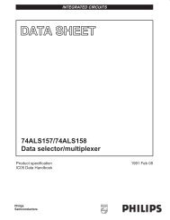
SEMICONDUCTOR TECHNICAL DATA The <strong>MC14506</strong>UB is an expandable AND–OR–INVERT gate with inhibitand 3–state output. The expand option allows cascading with any other gate,which may be carried as far as desired as long as the propagation delayadded with each gate is considered. For example, the second AOI gate inthis device may be used to expand the first gate, giving an expanded 4–wide,2–input AOI gate. This device is useful in data control and digital multiplexingapplications.• 3–State Output• Separate Inhibit Line• Diode Protection on All Inputs• Supply Voltage Range = 3.0 Vdc to 18 Vdc• Capable of Driving Two Low–Power TTL Loads or One Low–PowerSchottky TTL Load Over the Rated Temperature RangeMAXIMUM RATINGS* (Voltages Referenced to VSS)ÎÎÎÎÎÎÎÎÎÎÎÎÎÎÎÎÎÎÎÎÎÎÎÎÎÎÎÎÎÎÎÎÎÎÎÎÎÎÎÎÎÎÎÎÎÎÎÎÎÎÎÎÎÎÎÎÎÎÎÎÎÎÎSymbol Parameter Value UnitÎÎÎÎÎÎÎÎÎÎÎÎÎÎÎÎÎÎÎÎÎVDD DC Supply Voltage – 0.5 to + 18.0 VVin, Vout Input or Output Voltage (DC or Transient) – 0.5 to VDD + 0.5 VIin, IoutInput or Output Current (DC or Transient),per Pin± 10 mAPD Power Dissipation, per Package† 500 mWTstg Storage Temperature – 65 to + 150 CTL Lead Temperature (8–Second Soldering) 260 C* Maximum Ratings are those values beyond which damage to the device may occur.†Temperature Derating:Plastic “P and D/DW” Packages: – 7.0 mW/ C From 65 C To 125 CCeramic “L” Packages: – 12 mW/ C From 100 C To 125 CAA 1BA 2CA 3DA 4EA 5INH 6DIS 14EB 13DB 12CB 11BB 10AB 93–STATEOUTPUT DISABLELOGIC DIAGRAMZ = (AB + CD + E + I)15 ZAVDD = PIN 16VSS = PIN 87 ZBL SUFFIXCERAMICCASE 620ORDERING INFORMATIONMC14XXXUBCPMC14XXXUBCLMC14XXXUBDP SUFFIXPLASTICCASE 648D SUFFIXSOICCASE 751BPlasticCeramicSOICTA = – 55° to 125°C for all packages.This device contains protection circuitry toguard against damage due to high staticvoltages or electric fields. However, precautionsmust be taken to avoid applications ofany voltage higher than maximum rated voltagesto this high–impedance circuit. For properoperation, Vin and Vout should be constrainedto the range VSS (Vin or Vout) VDD.Unused inputs must always be tied to anappropriate logic voltage level (e.g., either VSSor VDD). Unused outputs must be left open.TRUTH TABLEA B C D E Inhibit Disable Z0 0 0 0 1 0 0 10 X 0 X 1 0 0 10 X X 0 1 0 0 1X 0 0 X 1 0 0 1X 0 X 0 1 0 0 11 1 X X X X 0 0X X 1 1 X X 0 0X X X X 0 X 0 0X X X X X 1 0 0X X X X X X 1 HighImpedanceX = Don’t CareREV 31/94© MOTOROLA Motorola, Inc. 1995 CMOS LOGIC DATA<strong>MC14506</strong>UB1
ELECTRICAL CHARACTERISTICS (Voltages Referenced to VSS)ÎÎÎÎÎÎÎÎÎÎÎÎÎÎÎÎÎÎÎÎÎÎÎÎÎÎÎÎÎÎÎÎÎÎÎÎÎÎÎÎÎÎÎÎÎÎÎÎÎÎÎÎÎÎÎÎÎÎÎÎÎÎÎÎÎÎÎÎÎÎÎÎÎÎÎÎÎÎÎÎÎÎÎÎÎÎÎÎÎÎÎÎÎÎÎÎÎÎÎÎÎΖ 55 C 25 C 125 CVDDVdc Min Max Min Typ # Max Min Max UnitÎÎÎÎÎÎÎÎÎÎÎÎÎÎÎÎÎÎÎÎÎÎÎÎÎÎÎÎÎÎÎÎÎÎCharacteristicSymbolUnitOutput VoltageVin = VDD or 0Vin = 0 or VDD“0” Level“1” LevelInput Voltage“0” Level(VO = 4.5 or 0.5 Vdc)(VO = 9.0 or 1.0 Vdc)(VO = 13.5 or 1.5 Vdc)VOL 5.01015VOH 5.01015VIL5.01015———4.959.9514.95———0.050.050.05———1.02.02.5———4.959.9514.95———0005.010152.254.506.750.050.050.05———1.02.02.5———4.959.9514.95———0.050.050.05———1.02.02.5VdcVdcVdc(VO = 0.5 or 4.5 Vdc)(VO = 1.0 or 9.0 Vdc)(VO = 1.5 or 13.5 Vdc)“1” LevelVIH5.010154.08.012.5———4.08.012.52.755.508.25———4.08.012.5———VdcOutput Drive Current(VOH = 2.5 Vdc)(VOH = 4.6 Vdc)(VOH = 9.5 Vdc)(VOH = 13.5 Vdc)SourceIOH5.05.01015– 3.0– 0.64– 1.6– 4.2————– 2.4– 0.51– 1.3– 3.4– 4.2– 0.88– 2.25– 8.8————– 1.7– 0.36– 0.9– 2.4————mAdc(VOL = 0.4 Vdc)(VOL = 0.5 Vdc)(VOL = 1.5 Vdc)SinkIOL 5.010150.641.64.2Input Current Iin 15 — ± 0.1 — ±0.00001 ± 0.1 — ± 1.0 µAdcInput Capacitance(Vin = 0)———0.511.33.40.882.258.8Cin — — — — 5.0 7.5 — — pF———0.360.92.4———mAdcQuiescent Current(Per Package)IDD 5.01015———1.02.04.0———0.0020.0040.0061.02.04.0———3060120µAdcTotal Supply Current**†(Dynamic plus Quiescent,Per Package)(CL = 50 pF on all outputs, allbuffers switching)IT 5.01015IT = (0.6 µA/kHz) f + IDDIT = (1.1 µA/kHz) f + IDDIT = (1.7 µA/kHz) f + IDDµAdcThree–State Leakage Current ITL 15 — ± 0.1 — ± 0.0001 ± 0.1 — ± 3.0 µAdc#Data labelled “Typ” is not to be used for design purposes but is intended as an indication of the IC’s potential performance.** The formulas given are for the typical characteristics only at 25 C.†To calculate total supply current at loads other than 50 pF:IT(CL) = IT(50 pF) + (CL – 50) Vfkwhere: IT is in µA (per package), CL in pF, V = (VDD – VSS) in volts, f in kHz is input frequency, and k = 0.002.PIN ASSIGNMENTAA116VDDBA215ZACA314DISABLEDA413EBEA512DBINH611CBZB710BBVSS89AB<strong>MC14506</strong>UB2MOTOROLA CMOS LOGIC DATA
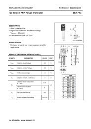
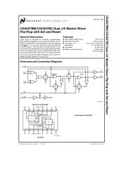
SWITCHING CHARACTERISTICS* (CL = 50 pF, TA = 25 C)ÎÎÎÎÎÎÎÎÎÎÎÎÎÎÎÎÎÎÎÎÎÎÎÎÎÎÎÎÎÎÎÎÎÎÎÎÎÎÎÎÎÎÎÎÎÎÎÎÎÎÎÎÎÎÎÎÎÎÎÎÎÎÎÎÎÎÎÎÎÎÎÎÎÎÎÎÎÎÎÎÎÎÎÎÎÎÎÎÎÎÎÎÎÎÎÎÎÎÎÎÎÎCharacteristic Symbol VDD Min Typ # Max UnitÎÎÎÎÎÎÎÎÎÎÎÎÎÎÎÎÎÎÎÎÎÎÎÎÎÎÎÎÎÎÎÎÎÎOutput Rise and Fall TimenstTLH, tTHL = (1.5 ns/pF) CL + 25 nstTLH, tTHL = (0.75 ns/pF) CL + 12.5 nstTLH, tTHL = (0.55 ns/pF) CL + 9.5 nsData Propagation Delay TimetPLH = (1.7 ns/pF) CL + 210 nstPLH = (0.66 ns/pF) CL + 77 nstPLH = (0.5 ns/pF) CL + 50 nstPHL = (1.7 ns/pF) CL + 185 nstPHL = (0.66 ns/pF) CL + 62 nstPHL = (0.5 ns/pF) CL + 40 nsExpand Propagation Delay TimetPLH = (1.7 ns/pF) CL + 95 nstPLH = (0.66 ns/pF) CL + 42 nstPLH = (0.5 ns/pF) CL + 25 nstPHL = (1.7 ns/pF) CL + 115 nstPHL = (0.66 ns/pF) CL + 47 nstPHL = (0.5 ns/pF) CL + 30 nsInhibit Propagation Delay TimetPLH = (1.7 ns/pF) CL + 135 nstPLH = (0.66 ns/pF) CL + 67 nstPLH = (0.5 ns/pF) CL + 40 nstPHL = (1.7 ns/pF) CL + 145 nstPHL = (0.66 ns/pF) CL + 62 nstPHL = (0.5 ns/pF) CL + 35 ns3–State Propagation Delay Time“1” to High ImpedancetTLH, tTHLtPLH5.010155.01015tPHL 5.01015tPLH5.01015tPHL 5.01015tPLH5.01015tPHL 5.01015tPHZ“0” to High Impedance tPLZ 5.01015High Impedance to “1” tPZH 5.01015High Impedance to “0” tPZL 5.01015* The formulas given are for the typical characteristics only at 25 C.#Data labelled “Typ” Is not to be used for design purposes but is intended as an indication of the IC’s potential performance.5.01015—————————————————————————————————10050402951107527095651807550200805522010065230956060453590554011050401707050200100805802251804801751404301601253301109050022516040017515015011090225140100300125100425175125nsnsnsnsnsnsnsnsnsns1616Vout , OUTPUT VOLTAGE (Vdc)1412108.06.04.02.000abcabc5.0 Vdc2.0 4.06.0a bc10 Vdc8.010Vin, INPUT VOLTAGE (Vdc)(a) Expand InputsVDD = 15 VdcUNUSED INPUTSCONNECTED TOVSSa TA = + 125°Cb TA = + 25°Cc TA = – 55°C121416Vout , OUTPUT VOLTAGE (Vdc)14 VDD = 15 Vdc121010 Vdca8.0 bc6.05.0 Vdc4.0ab2.0c00 2.0 4.06.0abc8.010Vin, INPUT VOLTAGE (Vdc)(b) Data InputsabcTA = + 125°CTA = + 25°CTA = – 55°CA AND B CONNECTED TO VinENABLE INPUT CONNECTED TOVDD. OTHER INPUTS CONNECTEDTO VSS.121416Figure 1. Typical Voltage Transfer CharacteristicsMOTOROLA CMOS LOGIC DATA<strong>MC14506</strong>UB3
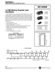
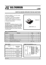
VDD16VDD16INHAABACADAEAABBBCBDBEBDISZAZBVOHIOHEXTERNALPOWERSUPPLYINHAABACADAEAABBBCBDBEBDISZAZBVOLIOLEXTERNALPOWERSUPPLY8VSS8VSSFigure 2. Typical Output SourceCharacteristics Test CircuitFigure 3. Typical Output SinkCharacteristics Test CircuitVDDVDD0.01 µFCERAMIC16INHAABACADAEAABBBCBDBEBDIS816ZAZBVSSVDDITLPULSEGENERATOR50% DUTY CYCLEBA500 µFINHAABACADAEAABBBCBDBEBDIS8ZAZBVSSIDDCLCLFigure 4. 3–State Leakage CurrentTest CircuitFigure 5. Typical Power DissipationTest Circuit<strong>MC14506</strong>UB4MOTOROLA CMOS LOGIC DATA
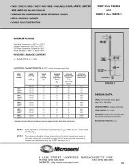
VDD16PULSEGENERATORINHAABACADAEAABBBCBDBEBDISZAZBINPUTOUTPUT20 ns 20 ns90%50%10%tPHL90%50%10%VDDVSStPLHVOHVOL8VSSCLCLtTHLtTLHFigure 6. Switching Time Test Circuit and Waveforms(Data Inputs)VDD Vout VDD16BAPULSEGENERATORS1INHAABACADAEAABBBCBDBEBDIS8ZAZBVSSCL1 kS2AB20 nsDISABLEINPUTtPLZOUTPUT90%50%10%10%90%tPHZ20 nstPZL90%tPZH10%VOH≈2.5 V @ VDD = 5 V,10 V AND 15 V≈ 2 V @ VDD = 5 V≈ 6 V @ VDD = 10 V≈ 10 V @ VDD = 15 VVOL* To test other side of circuit connect to this output andchange switch (S1) to other expand input (E).SWITCH POSITIONSTEST S1 S2tPLZ A AtPHZ B BtPZL A AtPZH B BFigure 7. Switching Time Test Circuit and Waveforms(For 3–State Output)MOTOROLA CMOS LOGIC DATA<strong>MC14506</strong>UB5
OUTLINE DIMENSIONSL SUFFIXCERAMIC DIP PACKAGECASE 620–10ISSUE V–T–SEATINGPLANEF–A–16 91 8EGD 16 PL0.25 (0.010) M TN–B–ASCKLMJ 16 PL0.25 (0.010) M TBSNOTES:1. DIMENSIONING AND TOLERANCING PERANSI Y14.5M, 1982.2. CONTROLLING DIMENSION: INCH.3. DIMENSION L TO CENTER OF LEAD WHENFORMED PARALLEL.4. DIMENSION F MAY NARROW TO 0.76 (0.030)WHERE THE LEAD ENTERS THE CERAMICBODY.INCHES MILLIMETERSDIM MIN MAX MIN MAXA 0.750 0.785 19.05 19.93B 0.240 0.295 6.10 7.49C ––– 0.200 ––– 5.08D 0.015 0.020 0.39 0.50E 0.050 BSC 1.27 BSCF 0.055 0.065 1.40 1.65G 0.100 BSC 2.54 BSCH 0.008 0.015 0.21 0.38K 0.125 0.170 3.18 4.31L 0.300 BSC 7.62 BSCM 0 15 0 15N 0.020 0.040 0.51 1.01P SUFFIXPLASTIC DIP PACKAGECASE 648–08ISSUE R16H–A–1 8GF9D 16 PLBSCK0.25 (0.010) M TSEATING–T– PLANEAMJLMNOTES:1. DIMENSIONING AND TOLERANCING PER ANSIY14.5M, 1982.2. CONTROLLING DIMENSION: INCH.3. DIMENSION L TO CENTER OF LEADS WHENFORMED PARALLEL.4. DIMENSION B DOES NOT INCLUDE MOLD FLASH.5. ROUNDED CORNERS OPTIONAL.INCHES MILLIMETERSDIM MIN MAX MIN MAXA 0.740 0.770 18.80 19.55B 0.250 0.270 6.35 6.85C 0.145 0.175 3.69 4.44D 0.015 0.021 0.39 0.53F 0.040 0.70 1.02 1.77G 0.100 BSC 2.54 BSCH 0.050 BSC 1.27 BSCJ 0.008 0.015 0.21 0.38K 0.110 0.130 2.80 3.30L 0.295 0.305 7.50 7.74M 0 10 0 10S 0.020 0.040 0.51 1.01<strong>MC14506</strong>UB6MOTOROLA CMOS LOGIC DATA
OUTLINE DIMENSIONSD SUFFIXPLASTIC SOIC PACKAGECASE 751B–05ISSUE J–T–SEATINGPLANE16 91 8G–A–D 16 PLK–B–P 8 PL0.25 (0.010) M B SC0.25 (0.010) M T B S A SMR X 45JFNOTES:1. DIMENSIONING AND TOLERANCING PER ANSIY14.5M, 1982.2. CONTROLLING DIMENSION: MILLIMETER.3. DIMENSIONS A AND B DO NOT INCLUDEMOLD PROTRUSION.4. MAXIMUM MOLD PROTRUSION 0.15 (0.006)PER SIDE.5. DIMENSION D DOES NOT INCLUDE DAMBARPROTRUSION. ALLOWABLE DAMBARPROTRUSION SHALL BE 0.127 (0.005) TOTALIN EXCESS OF THE D DIMENSION ATMAXIMUM MATERIAL CONDITION.MILLIMETERS INCHESDIM MIN MAX MIN MAXA 9.80 10.00 0.386 0.393B 3.80 4.00 0.150 0.157C 1.35 1.75 0.054 0.068D 0.35 0.49 0.014 0.019F 0.40 1.25 0.016 0.049G 1.27 BSC 0.050 BSCJ 0.19 0.25 0.008 0.009K 0.10 0.25 0.004 0.009M 0 7 0 7P 5.80 6.20 0.229 0.244R 0.25 0.50 0.010 0.019Motorola reserves the right to make changes without further notice to any products herein. Motorola makes no warranty, representation or guarantee regardingthe suitability of its products for any particular purpose, nor does Motorola assume any liability arising out of the application or use of any product or circuit,and specifically disclaims any and all liability, including without limitation consequential or incidental damages. “Typical” parameters which may be providedin Motorola data sheets and/or specifications can and do vary in different applications and actual performance may vary over time. All operating parameters,including “Typicals” must be validated for each customer application by customer’s technical experts. Motorola does not convey any license under its patentrights nor the rights of others. Motorola products are not designed, intended, or authorized for use as components in systems intended for surgical implantinto the body, or other applications intended to support or sustain life, or for any other application in which the failure of the Motorola product could create asituation where personal injury or death may occur. Should Buyer purchase or use Motorola products for any such unintended or unauthorized application,Buyer shall indemnify and hold Motorola and its officers, employees, subsidiaries, affiliates, and distributors harmless against all claims, costs, damages, andexpenses, and reasonable attorney fees arising out of, directly or indirectly, any claim of personal injury or death associated with such unintended orunauthorized use, even if such claim alleges that Motorola was negligent regarding the design or manufacture of the part. Motorola and are registeredtrademarks of Motorola, Inc. Motorola, Inc. is an Equal Opportunity/Affirmative Action Employer.How to reach us:USA/EUROPE/Locations Not Listed: Motorola Literature Distribution;JAPAN: Nippon Motorola Ltd.; Tatsumi–SPD–JLDC, 6F Seibu–Butsuryu–Center,P.O. Box 20912; Phoenix, Arizona 85036. 1–800–441–2447 or 602–303–5454 3–14–2 Tatsumi Koto–Ku, Tokyo 135, Japan. 03–81–3521–8315MFAX: RMFAX0@email.sps.mot.com – TOUCHTONE 602–244–6609ASIA/PACIFIC: Motorola Semiconductors H.K. Ltd.; 8B Tai Ping Industrial Park,INTERNET: http://Design–NET.com 51 Ting Kok Road, Tai Po, N.T., Hong Kong. 852–26629298MOTOROLA CMOS LOGIC DATA ◊<strong>MC14506</strong>UB/D7
This <strong>datasheet</strong> has been download from:www.<strong>datasheet</strong>catalog.com<strong>Datasheet</strong>s for electronics components.