JM60-433 - Sparesmaster
JM60-433 - Sparesmaster
JM60-433 - Sparesmaster
- No tags were found...

You also want an ePaper? Increase the reach of your titles
YUMPU automatically turns print PDFs into web optimized ePapers that Google loves.
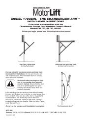
22Wiring the Multi-Function Door Control Paneland the Lighted Door Control Button (Optional)Locate any Wall Mounted Door Control where the garage dooris visible, away from door and door hardware, at a minimumheight of 1.5m. fasten the child warning label on the wall nearthe Door Control.There are 2 screw terminals (1) on the back of the Door Control(2). Strip about 6mm of insulation from bell wire (4). Separate wiresenough to connect the white/red wire to terminal screw 1 and thewhite wire to terminal screw (1).Lighted Door Control Button: Fasten to an inside garage wallwith sheet metal screws (3) provided with Lighted Push Button.Drill 4mm holes and use anchors (6) if installing into drywall orconcrete. A convenient place is beside the service door and out ofreach of children.Multifunction Door Control: Insert a small flat head screwdriverinto the top of the Wall Control (10), gently pry the cover off.Fasten to an inside garage wall with sheet metal screws (8) asfollows:• Install bottom screw, allowing 3mm to protrude from the wall.• Position bottom of door control over screw head and adjust forsnug fit.• Install top screw with care to avoid cracking plastic housing. Donot over tighten.• Replace cover by inserting bottom tabs (9) and snapping intoplace. To remove cover after mounting, gently pry at top withpaper clip or small flat head screwdriver.Run the bell wire up the wall and across the ceiling to the garagedoor opener. Use insulated staples (5) to secure wire.The opener Quick-Connect Terminals (7) are located in the recessnext to the learn button on the left side panel. Insert bell wire intoholes in the Quick Connect Terminals as follows: Red/White toRed and White to White.23Accessories(1) Model <strong>433</strong>5EML 3-Function Mini Remote Control(2) Model 770EML The Protector System(3) Model 747EML Wireless Keyless Entry Keypad(4) Model 845EML Multi-Function Door Control Panel(5) Model 75EML Lighted Door Control Button(6) Model 760EML Outside Keylock(7) Model 1702EML Outside Quick Release24Replacement Parts(1) 41A5644 Trolley with Chain/Cable Assy.(3 piece rail)041A0516-1 Trolley with Chain/Cable Assy(1 piece rail)(2) 041A6342 Head Only(3) 041A5643-4 Hardware Bag(4) 41B0668 Door Bracket(5) 41C0669 Header Bracket(6) 001A5644 Inner Trolley(7) 41C5620 Outer Trolley(8) 41C0521-1 Limit Switch (3 piece rail)041A0521-2 Limit Switch (1 piece rail)(9) 002D0838 1 piece rail(10) 41A5675 Rail Hardware(11) 41A5676 Rail Sections041A5626 Logic Board041A0157-1 TransformerSpecificationsInput Voltage . . . . . . . . . .230 VAC 50/60 HzMax. Pull force . . . . . . . .600NRated Power Input . . . . .85 WattsRated Load . . . . . . . . . . .3.0 NmStandby Power . . . . . . . .9 WattsMax. Door Weight . . . . . .60kgMotorType . . . . . . . . . . . . . . . .63:1 Worm Gear ReductionVolts . . . . . . . . . . . . . . . .24VDCDrive MechanismLength of Travel . . . . . . .2.8MTravel Rate . . . . . . . . . . .8cm/secLamp . . . . . . . . . . . . . . . .24V 21 WattsSafetyElectronic . . . . . . . . . . . .Auto-Force AdjustmentElectrical . . . . . . . . . . . . .Thermal Fuse in TransformerLimit Adjustment . . . . . . .ManualDimensionLength (Overall) . . . . . . .3.3mHeadroom Required . . . .30mmHanging Weight . . . . . . . .10kgReceiver Code RegistersBillion Code . . . . . . . . . . .12Dip Switch . . . . . . . . . . . .1Keypad . . . . . . . . . . . . . .1Operating Frequency . . .<strong>433</strong>.92MHz5-GB114A3269BPrinted in China