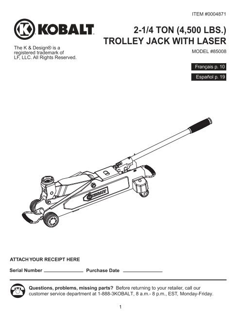
2-1/4 TON (4,500 LBS.) TROLLEY JACK WITH LASER
2-1/4 TON (4,500 LBS.) TROLLEY JACK WITH LASER
2-1/4 TON (4,500 LBS.) TROLLEY JACK WITH LASER
- No tags were found...

Create successful ePaper yourself
Turn your PDF publications into a flip-book with our unique Google optimized e-Paper software.
TABLE OF CONTENTSSafety Information .............................................................................................................................. 2Package Contents .............................................................................................................................. 4Preparation Before Use...................................................................................................................... 4Operation Instructions ........................................................................................................................ 5Care and Maintenance ....................................................................................................................... 7Troubleshooting.................................................................................................................................. 8Warranty............................................................................................................................................. 8Replacement Parts List ..................................................................................................................... 9SAFETY INFORMATIONBefore using this product, read this manual and follow all Safety Rules and Operational Instructions.Owner and/or Operator ResponsibilityThe owner and/or operator shall read and comprehend all instructions and warning labels for productand retain them for future reference.OperationThe owner and/or operator shall have an understanding of the product, its operating characteristics,safety precautions and operating instructions before operating the PALD (Portable Automotive LiftingDevice). Safety information shall be emphasized and understood. If the operator is not fluent inEnglish, the product instructions and safety recommendations shall be read to and discussed with theoperator in the operator's native language by the purchaser/owner or his designee, making sure thatthe operator comprehends their contents.WARNINGSafety Markings• Study, understand, and follow all instructions, safety precautions and warnings beforeoperating this device• Do not exceed rated capacity• Use only on hard, level surfaces• Use this product as a lifting device only. Immediately after lifting, support the vehiclewith appropriate means• Do not move or dolly the vehicle while on the jack• Failure to heed instructions, safety precautions or warnings may result in personal injuryand/or property damageSafety Messages• Lift only on areas of the vehicle as specified by the vehicle manufacturer• No alterations shall be made to this product2
P R N DALWAYS center any jackused under the axle ofvehicle or a suitable flat,reinforced surface.ALWAYS applyparking brake firmly.ONLY operatejack as alifting device.NOYESALWAYS support the weight ofthe load being lifted with jackstands rated at the propercapacity prior to beginning anyvehicle inspection or repairs.NEVER exceed the ratedcapacity of the jack stand. Ifrating is exceeded, loss of loadmay occur. ALWAYS place loadat center of jack stand's saddleto ensure stabilityof load.ONLY use liftingdevices on hard,level surfaces.Use on uneven orunstable surfacescould result ininstability and possiblefailure to support load.ALWAYS place chocksat front and rear of thevehicle's wheel thatwill NOT be lifted.ALWAYS use jack standsas supporting devices.Lifting operations mustALWAYS be done using aproper capacity jack.IncorrectCorrectONLY use this product as a lifting device.Immediately after lifting, support thevehicle with appropriate means.3
PACKAGE CONTENTSPARTABDESCRIPTIONJackPumping HandleQTY11ABIMPORTANT:DO NOT LOAD <strong>JACK</strong> BEYOND ITS RATED CAPACITY. NEVER MOVE THE <strong>JACK</strong> WHILE IT ISSUPPORTING A LOAD.PREPARATION BEFORE USEBefore using this product, make sure all parts are present. Compare parts with package contents list.If any part is missing or damaged, do not attempt to use the product. Contact customer service.During shipment or handling, air can become trapped in the hydraulic system of the jack, potentiallycausing the jack to malfunction.To purge air from the hydraulic system:1. Turn release valve counterclockwise with handle no more than two full turns.2. Slowly loosen oil fill plug.3. Pump jack handle quickly several times using full strokes.4. Repeat above steps as needed. Remember to retighten oil fill plug.IMPORTANT:The release valve is to be used only to open and close the hydraulic system. Under no circumstancesis it to be used as a point of temporary connection between the handle and jack for the purpose ofpushing and/or pulling the jack. This action can and will damage the release valve and cause the unitto fail.4
OPERATION INSTRUCTIONSTO RAISE1. Place vehicle in PARK (vehicles with automatic transmissions) or in GEAR(vehicles equipped with standard transmissions) and apply emergency brake.2. Close release valve tightly by turning handle clockwise.3. Center jack under load so that saddle contacts load firmly and will not slip.(Refer to vehicle Owner's Manual for proper lifting points.)4. Pump handle up and down until saddle contacts load. Check to ensure that saddle is centeredcorrectly under lifting point before continuing. If not, re-center and continue.5. Raise load to desired height and place jack stands in correct position. Open the release valve onthe jack slightly and SLOWLY transfer load from the jack to the jack stands. When the load issecure on jack stands, lower jack completely and remove from under the vehicle.6. Reverse above procedure to remove jack stands.TO LOWERUsing handle as a wrench turn the release valve counterclockwise VERY SLOWLY.Continue until vehicle is completely on the ground.Laser Targeting DeviceThis jack has been fitted with a laser targeting device. This device is designed to assist the operatorto properly position the saddle of the jack under the lifting point on the undercarriage of the vehiclebeing lifted.WARNING: Laser targeting devices or pointers are not to be used forentertainment. This device is to be used only as a targeting device to assist theoperator when positioning the jack under a vehicle. NEVER point laser targeting deviceat anyone's eyes.CAUTION: Use of controls or adjustments or performance ofprocedures other than those specified herein may result inhazardous radiation exposure.CAUTION: The use of optical instruments with this product willincrease eye hazard.CAUTION: Do not attempt to repair or disassemble the laser. Ifunqualified persons attempt to repair this laser product, seriousinjury may result. Any repair required on this laser productshould be performed by authorized service center personnel.AVOID EXPOSURE - Laser radiationis emitted from this apertureD A N G E R<strong>LASER</strong> RADIATIONAVOID DIRECT EYE EXPOSUREMAX. OUTPUT POWER < 5mWWAVELENGTH 630-680 nmCLASS IIIA <strong>LASER</strong> PRODUCTComplies with 21 CFR 1040. 10 and 1040.115
OPERATION INSTRUCTIONS (continued)1. To turn laser targeting device "ON", using indexfinger, push down on rubber retainer cap (A)located in center of jack's saddle.2. Position jack under vehicle to be lifted.3. A target will be projected onto the undercarriageof vehicle.4. To turn laser targeting device "OFF", using indexfinger, push down on rubber retainer cap locatedin the center of jack's saddle.AREMOVE/INSTALL BATTERIES IN <strong>LASER</strong>MODULE (Use LR41 Button Battery, 3ea.)1. Remove the rubber retainer cap (A) bypulling upward.2. Remove the laser module (B) from the saddle.3. While holding body of laser module (B), twistand pull the end cap assembly (C) and removethe old batteries from inside the body.NOTE: When removing the batteries andinstalling the new ones, note the orientation ofthe battery cells and make sure to install thenew cells in the same manner.4. Reinstall the end cap assembly (C) by firmlypushing onto the laser module (B) until fullyseated.5. Replace laser module back into the receptaclein the saddle with switch end (D) down and thelens cover facing up.6. Replace the rubber retainer cap.CBD6