PSS Shaft Seal Install Instructions - PYI Inc.
PSS Shaft Seal Install Instructions - PYI Inc.
PSS Shaft Seal Install Instructions - PYI Inc.

You also want an ePaper? Increase the reach of your titles
YUMPU automatically turns print PDFs into web optimized ePapers that Google loves.
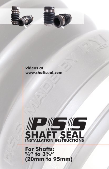
videos atwww.shaftseal.comSHAFT SEALINSTALLATION INSTRUCTIONSFor <strong>Shaft</strong>s:¾” to 3¾”(20mm to 95mm)
IMPORTANT INSTRUCTIONS-READ BEFORE STARTING!IMPORTANT! - BEFORE STARTING YOUR INSTALLATION CAREFULLYREAD THE FOLLOWING WARNINGS AND INSTRUCTIONS. FAILURETO PROPERLY FOLLOW THE WARNINGS AND INSTRUCTIONSCOULD LEAD TO PERSONAL INJURY OR EVEN DEATH, OR PHYSICAL,ENVIRONMENTAL OR PROPERTY DAMAGE.• READ AND FOLLOW THE INSTRUCTIONS THOROUGHLY! The <strong>PSS</strong> (Packless <strong>Seal</strong>ing System) <strong>Shaft</strong><strong>Seal</strong> (“<strong>PSS</strong>”) you are preparing to install is a through-hull fitting that protects against water fromentering the boat where the shaft enters the hull, when properly installed and maintained. Makesure that you or your designated installer is a qualified professional, knowledgeable and skilled tointsall the <strong>PSS</strong> correctly, and you have all the required tools and additional equipment on hand beforebeginning installation.• If removing the engine transmission for repair or if launching the boat without a transmission installed,then the shaft must be kept in place with a device that will secure the shaft with the <strong>PSS</strong> below in itsnormal “compressed mode”.• <strong>Install</strong> the <strong>PSS</strong> ONLY with the boat out of the water.• DO NOT USE oil, grease (petroleum products) or silicone products at any time during the installation.Use soap and water to lubricate the o-rings of the rotor when sliding it down the shaft.• Clean the seal area of your boat so you do not contaminate the seal surface with dirt, oil or otherforeign matter. Do not damage or scratch the face of the carbon or the face of the stainless steel rotorduring unpacking or while handling or installing the <strong>PSS</strong>.• There should be a total of four (4) set screws in the two holes of the rotor (2 sets screws in each hole).If you must move the stainless steel rotor, make sure to remove the top set screws in order to access thebottom two set screws.• Do not re-use the supplied cupped pointed set screws. If multiple tightening has flattened the cuppedpointset screw, replace the affected screw with a new one.• There should be a total of four (4) hose clams securing the bellows ends. These clamps should bereplaced if they show any sign of corrosion.• Replace the nylon barb if seal runs dry.• Do not tighten or replace the installed nylon hose barb fitting with a metallic fitting (bronze or stainlesssteel). Metal hose barbs will damage the carbon and destroy the <strong>PSS</strong>.• Do not slide the aft bellow cuff too far down over the stern tube. The leading edge of the stern tubecould cause damage to the inner ribs of the bellow and improperly limit the bellow movement andtravel.• If fitting a vent line (boats under 12 knots), do not run a loop at the top end of the hose as this couldpromote a siphon and water could be near it.• If the boat sits idle for a long period of time (generally 3 months or more), it is necessary to move thecarbon face back to allow a small amount of water to enter the boat.• As with any hose under the waterline, the <strong>PSS</strong> bellows must be inspected on a regular basis (i.e., noless than at least every 6 months under most circumstances) and checked for any signs of deterioration(cracks, splits, tears, brittleness, or other signs). Upon any sign of deterioration the bellow must bereplaced. As preventive maintenance the bellow should be replaced no less than every six (6) years,regardless of its apparent condition.• Do not allow any petroleum-based liquid or corrosive material to come in contact with the <strong>PSS</strong>. Takecare to ensure that this does not occur, for example, when performing any general maintenance, orwinterizing the engine.• The shaft should be near centered and run parallel to the shaft log.• Do not use an ozone generator (e.g., air cleaner) in or around your boat. The extra ozone will speedup the deterioration of any rubber product, including the <strong>PSS</strong> bellow.• The bellows will need more frequent inspection and replacement in an environment where non-sealedbatteries emit sulfuric acid vapors. Sulfuric acid vapors will accelerate deterioration of any rubbermaterials including the <strong>PSS</strong> bellows.• Do not use sealant to fit the bellow to the stern tube or the hose to hose barb.• Do not run dry.• Do not use the <strong>PSS</strong> SEAL on a submarine vehicle.1
INSTALLATION INSTRUCTIONS1 Propeller <strong>Shaft</strong>62 <strong>Shaft</strong> Log (Stern Tube)7345Stainless Steel Hose Clamps x4Nitrile Bellow x1Carbon Graphite Flange x189Stainless Steel Rotor x1Stainless Steel Set Screwsx5 / 4 for rotor, 1 spareNitrile O-Rings2 in rotor / 2 spareNylon Hose Barb Fitting10 Clamp Jackets x4IN ALL CASES, THE BOAT MUST BE OUT OF THE WATER TO PERFORM THISINSTALLATION.1. Unbolt the shaft coupling from the transmission coupling.2. Remove the shaft coupling from the shaft. Coupling styles will vary by manufacturer.Some couplings use set screws to keep the coupling in place, while others use a rollpin and others use a nut (always use the appropriate tools and procedures for yourparticular application).3. Remove the old stuffing box and packing material. There are three types of packingglands that can be found on most boats: “Classic”, “Bolt On” and “Threaded”.4. Clean the entire exposed portion of the shaft with very fine sand paper (# 400 or# 600 grit) in order to remove any debris or rough edges. Pay particular attention tothe keyway located at the forward end of the shaft, where the stainless steel rotor willpass. The shaft and keyway must NOT have any sharp edges that could damage theo-rings upon installation.2
5. Slide the open end of the bellow and its hose clamps down the shaft and onto thebare stern tube and make sure the bellow has a proper fit over the shaft log. Once inplace the bellow should overlap the stern tube by the same amount as the bellow cuffso the hose clamps will properly tighten the bellow to the shaft log. WARNING: Do notslide the bellow cuff too far down and over the stern tube. If the bellow is slid too faronto the stern tube the forward edge of the stern tube could damage the inner ribs ofthe bellow and improperly limit the bellow’s travel. Tighten the hose clamps to securethe bellow to the stern tube and fit the black clamp protector to the tail of the hose clamps.6. Make sure the carbon flange is in place on the forward end of the bellow and thatthe two hose clamps properly secure it. Also confirm that the carbon is free of anydefects or imperfections on its polished face.7. Remove the stainless steel rotor from the protective pouch. Verify that there are two(2) o-rings placed into the o-ring grooves inside the bore of the rotor. Confirm that themating face of the rotor is free of any defects or imperfections. Take two (2) (Two Only)of the set screws from the plastic bag and thread them into the rotor holes. Save theremaining set screws for use later during installation. Thread one screw into each hole,stopping just short of the screw protruding into the inside bore of the rotor.8. Lubricate the shaft and o-rings of the rotor, and slide the stainless steel rotordown the shaft. Use a petroleum free liquid (e.g., a dish soap / water solution workswell) as the lubricant. Caution: DO NOT USE OIL, GREASE OR SILICONE AS THELUBRICANT.9. Re-attach the shaft coupling to the shaft and make sure that all the safety devicesprovided and recommended by the coupling manufacturer are in place.10. Re-attach the shaft coupling to the transmission making sure that it is installedto the manufacturer specifications and tolerances. Make sure all the safety devicesprovided and recommended by the coupling manufacturer are in place.11. Now that the shaft is in place, verify that the carbon is centered on the shaft (notethe carbon ring is bored at a larger diameter than the shaft), verify that the bellow cuff isproperly placed on the stern tube and verify that the shaft is near center in the shaft log.Adjust accordingly. Tighten all the hose clamps around the stern tube and the carbon.BELLOW COMPRESSION CHART<strong>Shaft</strong> DiameterCompression Amount¾” to 1⅜”(20mm to 35mm)1½” to 3¾”(38mm to 95mm)3¾”(20mm)1”(25mm)
12. Slide the stainless steel rotor down the shaft until it just TOUCHES the carbon.Mark this position on the shaft as the “neutral” position with a marker or a piece oftape on the shaft just in front of the rotor.13. Sliding the stainless steel rotor aft, compress the bellow by the amount indicatedon the bellow compression chart, using the “neutral” mark as a reference point. Whilekeeping the bellow in the “compressed” position, tighten the two (2) set screws againstthe shaft with the provided allen wrench (Use approximately 6 foot pounds of torquefor shafts ¾” to 1⅜” and 8 foot pounds of torque for shafts 1½” to 3¾”. If you needto insert the long arm of the allen wrench into the hole, a vice-grip, for example, maybe fitted on the short arm to help provide the required torque.14. Remove from the plastic bag two (2) additional set screws, and thread one intoeach hole and tighten them against the first set screws. This will act as a locking devicefor the first set screws. Do not re-use cupped point set screws.15. Plumbing the system:Note: Sailboats or displacement powerboats with a powering speed below 12 knotscan use either method A or B. However, displacement boats with a bearing in theshaft log must plumb water to the seal.15A. Low speed boats: (Under 12 knots of boat speed under power and no bearingin the shaft log).Using a ⅜” (8 or 9 mm) ID “underwater rated” hose (not provided with the <strong>PSS</strong>),connect the hose to the hose barb fitting installed on the carbon and secure the hosewith two (2) hose clamps. Run the hose to a point in the boat at least two (2) feetabove the waterline, making sure that the hose does not apply any load on the carbonpart of the seal. Keep the hose as close as possible to the centerline of the vessel sothe top of the vent hose is never below the waterline, even if the boat heels. Secure thehose in place with the necessary fittings that insure it will not pull free and drop. Thishose is now a venting hose that will help ensure that no air is trapped in the seal.WARNINGS: Do not run a loop at the top end of the vent hose as it could start asiphon action in some extreme conditions. Also, make sure the vent hose is properlysecured from falling below the waterline. If the vent hose were to fall down below thewaterline, water would come in the boat. Also, do not plug or block the end of thevent hose, as this would prevent the line from venting.15B. High-speed boats: (Over 12 knots of boat speed under power).Note: Boats that can exceed 12 knots on a single engine must run a crossover linebetween seals to ensure both seals maintain water flow.4
For high-speed vessels it is required that a water supply be plumbed to the <strong>PSS</strong> for thepurpose of cooling and lubricating the seal faces (i.e., at over approximately 12 knotsof speed a vacuum is created in the stern tube and water is drawn away from the <strong>PSS</strong>resulting in a loss of cooling water that may cause the carbon to over heat). There aremultiple sources of water for the supply. The following are a few non-exhaustive examples.These are examples only and they may or may not apply to your particular boat.-T-off the engine raw water-cooling line. (Note:T-kits are available separately from <strong>PYI</strong><strong>Inc</strong> for internal hose ¾”, 1” , 1¼”, 1½”)-Thread a barb fitting into the drain plug of the heat exchanger if applicable.-Thread barb fitting into the drain plug of the exhaust manifold if the manifold is rawwater-cooled.-Add a small scoop under water for keel-cooled boats or T-off another water pickup. (Note: A valve must be installed to regulate the water flow as too high water flowmay over pressurize the <strong>PSS</strong> seal). Use an appropriate “underwater rated” hose fromthe fittings on the boat and the fitting on the <strong>PSS</strong> and secure them with two (2) hoseclamps at each end.NOTICE: All plumbing must follow the standards and practices of proper boatplumbing. For example, if the pick-up on the engine is located under the waterline, ananti-siphon fitting must be installed, in addition to other standards and practices.16. Testing: When launching the boat, inspect the <strong>PSS</strong> and make sure the <strong>PSS</strong> isproperly in place. Water should not be entering the boat from the <strong>PSS</strong> seal area. Runthe engine in gear as in a normal operation. It is normal at this time to notice a veryfine spray or mist coming from the seal and some carbon dust, as the <strong>PSS</strong> requires abreak in period (see below). The <strong>PSS</strong> should not be leaking at rest and should neverspray more than just a fine spray or mist.TROUBLESHOOTINGA. High-pitched squeal:If you hear a high-pitched squeal from the <strong>PSS</strong> shaft seal duringoperation, the seal may not be getting water. Review and correctplumbing to the seal.CAUTION: If the seal has run dry use caution! The faces(stainless steel rotor and carbon) may be very hot.5
B. Spray or mist during operation after the break inperiod:The dimensions provided in the “Bellow compression chart” are averagefigures and are provided as a guide. The EXACT compression amountsrequired can vary due to different types of engine mouts and waterpressure being fed to the seal. If you experience any spray or mistfollowing the break in period, make sure that the bellows had beencompressed properly. If so, add an additional ¼” of compression to theseal and soon the mist should disappear. Keep adjusting until the sprayor mist stops.C. Dripping at rest:If the <strong>PSS</strong> seal drips while at rest then it is likely that foreign material ison the face of the seal between the stainless steel rotor and the carbonflange. To clean this foreign material from the seal, insert a clean ragcarefully between the two faces (Note: some water will come into theboat at this time if the boat is in the water) and work the rag aroundthe seal. As you do this, the incoming water will flush the impurities.Remove the rag from the seal and the leak should stop.BREAK-IN PERIODOn average, the <strong>PSS</strong> requires approximately one (1) hour of break in time, whichallows the carbon flange to polish the mating face of the stainless steel rotor. Duringthe break in period you will experience a very fine mist, sometimes associated witha black dust coming from the <strong>PSS</strong>. Under normal conditions, this will stop after anaverage of one (1) hour running time.Copyright © 2011 <strong>PYI</strong>, <strong>Inc</strong>. All rights are reserved. No part of this document maybe reproduced, transmitted, transcribed, stored in a retrieval system, or translated intoany language or computer language, in any form or by any means, without the priorwritten permission of <strong>PYI</strong>, <strong>Inc</strong>.<strong>PYI</strong>, <strong>Inc</strong>. makes no representations or warranties, express or implied, with respect tothis document or the contents herin and specifically disclaims any implied warranties ofmerchantability or fitness for any particular purpose. In addition, <strong>PYI</strong>, <strong>Inc</strong>. reserves theright to revise this document and to make changes from time to time in the content herof.6
<strong>PYI</strong>, <strong>Inc</strong>.LIMITED WARRANTY / LIMITATIONS OF REMEDIES AND LIABILITYP.S.S. (Packless <strong>Seal</strong>ing System) <strong>Shaft</strong> <strong>Seal</strong>Grant of Limited Warranty. The <strong>PSS</strong> (Packless <strong>Seal</strong>ing System) <strong>Shaft</strong> <strong>Seal</strong> (“<strong>PSS</strong>”)is warranted by <strong>PYI</strong>,<strong>Inc</strong>. (“<strong>PYI</strong>”)to the original purchaser only to be free from defects in material and workmanship under normaluse and maintenance for a period of three (3) years from the date of first use or shipment, whichever comesfirst. During the warranty period, all original parts subject to this limited warranty and determined by <strong>PYI</strong> tobe defective in materials or workmanship, will either be repaired or replaced by <strong>PYI</strong> or its authorized agent,at its sole option, free of charge, except for shipping and handling charges and dealer labor charges (ifapplicable), which charges are not covered by this limited warranty. The warranty on any part repaired orreplaced under this limited warranty expires at the end of the original warranty period.Limitations of Limited Warranty. This limited warranty does not cover and does not apply to any <strong>PSS</strong>:(i) altered in any way inconsistent with the shaft seal design as provided, (ii) improperly installed and/ormaintained, (iii) incompatible with any portion or component of any boat or application that is not suppliedby <strong>PYI</strong>, regardless of the cause of the failure or incompatibility of such portion or component, (iv) used forpurposes other than those for which it was designed, and/or (v) subjected to misuse, neglect or accidents.In order to obtain warranty service, the <strong>PSS</strong>, together with the bill of sale or other dated proof-of-purchasedocument identifying the shaft seal model number, must be presented to an authorized <strong>PSS</strong> dealer duringthe warranty period. For assistance in locating an authorized <strong>PSS</strong> dealer, please contact <strong>PYI</strong> at:<strong>PYI</strong>, <strong>Inc</strong>.12532 Beverly Park RoadLynnwood, WA 98087Phone: 425-355-3669Except for the limited warranty expressly provided above, to the maximum extent permitted by applicablelaw, <strong>PYI</strong> and its suppliers make no warranties, express or implied, and disclaim all warranties, duties andconditions, whether express, implied or statutory, with respect to the <strong>PSS</strong>, including, without limitation, anyimplied warranties of merchantability, against latent defects, fitness for a particular purpose, or correspondenceto description.Limitation of Remedies. In the event of a breach of the limited warranty set forth above, <strong>PYI</strong> or itsauthorized agent will only be obligated at <strong>PYI</strong>’s sole option to either repair or replace the failed <strong>PSS</strong>. Ifafter written notice to <strong>PYI</strong> of each defect, malfunction or other failure and a reasonable number of attemptsto correct the defect, malfunction or other failure and the remedy fails of its essential purpose, <strong>PYI</strong> shallrefund the purchase price paid to <strong>PYI</strong> in exchange for the return of the sold good(s). Said refund shall bethe maximum liability of <strong>PYI</strong>. THE FOREGOING REMEDY IS THE SOLE AND EXCLUSIVE REMEDY OF THEBUYER AGAINST <strong>PYI</strong> REGARDLESS OF THEORY, WHETHER ARISING IN CONTRACT, BREACH OF ANYWARRANTY, TORT, INCLUDING STRICT LIABILITY OR NEGLIGENCE, OR OTHERWISE.Limitation of Liability. To the maximum extent permitted by applicable law, <strong>PYI</strong> and its suppliersexpressly disclaim and exclude any liability for any incidental, special, indirect or consequential damagesresulting from any reason whatsoever. This exclusion applies to all legal theories under which damages maybe sought.Note: This limited warranty gives you specific legal rights and you may also have other rights which mayvary from state to state.Please refer to the P.S.S. <strong>Shaft</strong> <strong>Seal</strong> Instruction Booklet for installation instructions.12532 Beverly Park Road Lynnwood, WA 98087(425) 355-3669 Fax: (425) 355-3661info@pyiinc.com www.pyiinc.comwww.shaftseal.com