nextGeneration II 2x7-280, 14-280, 14-350 - Schulze Elektronik GmbH
nextGeneration II 2x7-280, 14-280, 14-350 - Schulze Elektronik GmbH
nextGeneration II 2x7-280, 14-280, 14-350 - Schulze Elektronik GmbH

You also want an ePaper? Increase the reach of your titles
YUMPU automatically turns print PDFs into web optimized ePapers that Google loves.
4<br />
Page Issue 03.10<br />
Operating<br />
instructions<br />
Issue 03.10, page<br />
<strong>nextGeneration</strong> <strong>II</strong> Firmware version V 1.00 and higher<br />
<strong>nextGeneration</strong> <strong>II</strong> Firmware V 1.00 and higher 45<br />
• Protect the charger from direct exposure to the sun (the sun´s heat may temporarily turn the LCdisplay<br />
black), dust, moisture and rain(!).<br />
Even though the schulze chargers are smart (they are micro-processor equipped and can determine a<br />
battery’s number of cells and its optimum charge current pattern), attempting to charge the following<br />
packs should not be attempted:<br />
• batteries built up from cells of different types and capacities<br />
• batteries made from different types of single cells<br />
• batteries with a different charging level of the cells<br />
• non rechargeable cells (dry cells)<br />
• batteries which are not expressly designed for fast charging and recharging.<br />
• defective or damaged packs or cells<br />
• already fully charged and/or hot batteries<br />
• battery packs with internal charge-current limiting devices (not valid for <strong>Schulze</strong> LiPoTx und LiPoRx)<br />
• batteries which are buildt-in (internal) to other equipment<br />
Do not exceed a battery’s design (maximum) charge current as specified by its manufacturer; note that the<br />
schulze chargers will still optimally charge these packs in automatic charging mode; you can program<br />
the charger’s max (limit) charge current.<br />
• Please bear in mind that new rechargeable batteries do not achieve their full capacity until they have<br />
completed several charge / discharge cycles. New batteries generally, and deep-discharged Nickel<br />
batteries in particular, may cause premature charge termination. For this reason it is absolutely essential<br />
to check that the automatic charge cut-off circuit works correctly and reliably; this is achieved by carrying<br />
out several test-charges, and checking the quantity of capacity charged into the pack.<br />
When charging battery packs with less than 4 nickel cells, exercise extra care to make sure that these are<br />
not over-charged (especially when you use less than the specified current for this battery type - see<br />
chapter 4). Packs which are (too) deeply discharged may cause the charger to cut off too soon.<br />
New batteries will only achieve their maximum capacity after several charge/discharge cycles; schulze<br />
chargers can be programmed to provide these cycles automatically.<br />
Please remember that battery packs can heat up considerably especially during multiple charge/discharge<br />
cycles; program your charger’s max discharge current to prevent overheating of the packs unless you<br />
provide additional cooling (some of the racing pilots use a tube with electric fan cooling!). Note that packs<br />
with low capacity will dangerously overheat at high discharge currents; the schulze charger can (and)<br />
should in this case be programmed to the limit discharge rate to a more acceptable level, for instance 1C<br />
and/or a battery cooler in combination with the temperature sensor for cut-off must be used. You can also<br />
use our build in low-temperature-start circuit. (Do not forget to activate temperature sensor to the right<br />
pack output and fix it at the right battery.)<br />
• Safety hint: Always verify the charge amount which your battery has absorbed (mAh or Ah) after a full<br />
charge (this is indicated on the display panel); this is probably the best gauge of a battery’s health and/or<br />
the proper operation of the charger. This way, you will avoid unexpected loss of power and/or control.<br />
An additional important function is the selection of the automatic cut-off circuit. Read the important comments<br />
in Chapter 12). Maximum protection against malfunctions of the cut-off automatic is provided by<br />
selecting additional cut-off criterias like max. temperature, max. energy input and max. charge time.<br />
For trouble-free operation, please check …<br />
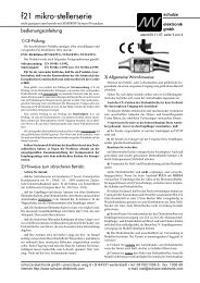
… that the ferrite ring in the charge lead does not fracture. The ring prevents the charge lead acting as an<br />
aerial, i.e. radiating the pulsed frequency of the voltage converter and the processor in an unacceptable<br />
way. It is absolutely essential if the charger is to operate in the manner required for CE approval.<br />
… that the charge leads used for the Battery 1 and 2 outputs are as short as possible. The maximum total<br />
cable length - from the sockets to the battery - should be no longer than 70 cm. Twist the wires together<br />
to help suppress interference.<br />
… that the charge lead for charge output 1 is wound through one of the ferrite CE rings at least four times.<br />
These rings are probably familiar to you from long servo extension leads, albeit in a different size.<br />
The ring must be located no more than 5 cm from the banana plugs which are attached to the chargers end<br />
of the charge lead.<br />
27.5 Standard Balancing Adapters<br />
We offer a selection of printed circuit adapter boards which allow the balancing of 2s-7s (...<strong>14</strong>s)<br />
battery packs which are equipped with the most different balancing connectors. The balancing<br />
adapter boards are fitted with a cable containing an 8 pin EH socket - suited for the EH connector<br />
of the nextGen.<strong>II</strong>.<br />
27.5.1 BalAd-Set7 for battery 1 and/or battery 2<br />
Set containing 4 adapter PCBs with different plug systems (EH, XH, PQ, TP)<br />
and each with different pin counts to connect 2s ... 7s battery packs.<br />
27.5.2 BalAd-EH7 for battery 1 and/or battery 2<br />
Adapter PCB equipped with 6 EH male connectors of different pin counts<br />
to connect 2s ... 7s battery packs<br />
27.5.3 BalAd-XH7 for battery 1 and/or battery 2<br />
Adapter PCB equipped with 6 XH male connectors of different pin counts<br />
to connect 2s ... 7s battery packs<br />
27.5.4 BalAd-PQ7 for battery 1 and/or battery 2<br />
Adapter PCB equipped with 6 PQ male connectors of different pin counts<br />
to connect 2s ... 7s battery packs<br />
27.5.5 BalAd-TP7 for battery 1 and/or battery 2<br />
Adapter PCB equipped with 4 TP male connectors of different pin counts<br />
to connect 2s ... 7s battery packs<br />
27.5.6 BalAd-EH<strong>14</strong>. For battery 1 use only - due to the fact that all <strong>14</strong> balancing circuits<br />
can be used and the second balancing group is no longer available for battery 2.<br />
• Adapter PCB equipped with 13 EH male connectors of different pin counts<br />
to connect 2s ... 24s battery packs which can be separated into 2 packs.<br />
Note: When the packs are combined or equipped with two connectors then it is essential<br />
that the pack with the lower cell count (2...7) has to be connected to the balancing output<br />
EH1 of the charger - and also with the black ("-") power cable to the charge output 1.<br />
27.6 <strong>Schulze</strong> Balancinbg Cables<br />
The sets are assorted to make 10- and 20-pin. balancing cables<br />
which can be coded battery typical - to allow „plug-and-play“<br />
charging of your batteries with modern <strong>Schulze</strong> chargers.<br />
Note: A detailled description of the pinout and the mounting<br />
instructions are enclosed in the balancer cable kits<br />
(BalCab10 or 20 - Set).<br />
BalCab10-Set/BalCab20-Set BalCab10/20-Verlängerung<br />
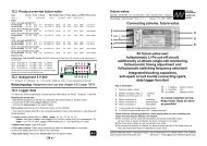
The principle of connection<br />
of <strong>Schulze</strong> Balancers<br />
(cell arrangement as the storeys in<br />
a high-rise building)<br />
+ cell 7 (seventh storey)= + battery<br />
+ cell 6 (sixth storey) = - cell 7<br />
+ cell 5 (fifth storey) = - cell 6<br />
+ cell 4 (fourth storey) = - cell 5<br />
+ cell 3 (third storey) = - cell 4<br />
+ cell 2 (second storey)= - cell 3<br />
+ cell 1 (first storey) = - cell 2<br />
- cell 1 (ground floor) = earth = - battery