nextGeneration II 2x7-280, 14-280, 14-350 - Schulze Elektronik GmbH
nextGeneration II 2x7-280, 14-280, 14-350 - Schulze Elektronik GmbH
nextGeneration II 2x7-280, 14-280, 14-350 - Schulze Elektronik GmbH

You also want an ePaper? Increase the reach of your titles
YUMPU automatically turns print PDFs into web optimized ePapers that Google loves.
48<br />
Page Issue 03.10<br />
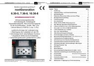
30 Installing the<br />
nextConn-<strong>II</strong> module<br />
The next-XX-XXX-“eco“ types are<br />
supplied as standard without nextConn-<br />
<strong>II</strong> module. The nextConn-<strong>II</strong> module can<br />
very easily be installed if required.<br />
Note: Opposite figures similar.<br />
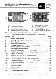
30.1 Opening the case<br />
Undo the six cross-point screws (1 – 6)<br />
and remove the bottom case section.<br />
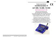
30.2 Installing the nextConn-<strong>II</strong> module<br />
and the side panel insert<br />
31.2.1 Remove the side panel (8) and<br />
replace it with the new, perforated panel.<br />
You may find that the side panel comes<br />
away together with the bottom case<br />
section.<br />
30.2.2 Locate the ten holes in the<br />
smooth underside of the nextConn-<strong>II</strong><br />
module (9) and position them directly<br />
over the ten connector pins (7) mounted<br />
on the large base circuit board. Don’t<br />
use force! The nextConn-<strong>II</strong> module will<br />
automatically (!) fall into place on the<br />
base circuit board if correctly positioned.<br />
Check that the two nylon screws engage<br />
in the corresponding holes in the base<br />
circuit board.<br />
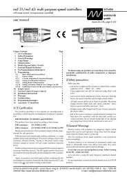
30.3 Pressing the nextConn-<strong>II</strong> module<br />
into place<br />
Press the nextConn module down<br />
gently as far as it will go, to ensure that<br />
the connectors make good contact.<br />
The tips of the connector pins (7) must<br />
be exposed at the top of the ten-pin<br />
socket (10).<br />
30.4 Closing the case<br />
Position the bottom case section<br />
accurately on the top case section,<br />
taking care to engage the side panels<br />
correctly.<br />
Re-fit the screws (1 – 6); take care not<br />
to over-tighten them.<br />
Note: the nextConn-<strong>II</strong> module is not<br />
screwed to the base circuit board.<br />
Nevertheless, it is held in place securely<br />
by the moulded-in supports (13 – 16) and<br />
the two nylon screws (11 – 12) when the<br />
case components are screwed together.<br />
<strong>nextGeneration</strong> <strong>II</strong> Firmware V 1.00 and higher<br />
Fig.<br />
31.1<br />
Fig. 31.2<br />
12<br />
9<br />
Fig.<br />
31.3<br />
1 2<br />
3 4<br />
5 6<br />
10<br />
8<br />
8<br />
13<br />
7<br />
11<br />
<strong>14</strong><br />
7<br />
16<br />
15<br />
12<br />
Fig. 31.4<br />
8<br />
<strong>nextGeneration</strong> <strong>II</strong> Firmware version V 1.00 and higher<br />
Contents<br />
Operating<br />
instructions<br />
Issue 03.10, page<br />
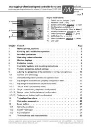
Chapter Topic Page<br />
1 General information . . . . . . . . . . . . . . . . . . . . . . 2<br />
2 General remarks and precautions . . . . . . . . . . . . . . 3<br />
3 Commonly used terms . . . . . . . . . . . . . . . . . . . . 5<br />
4 Useful information about batteries and maintenance . . . . 6<br />
5 Mounting instructions CE ring . . . . . . . . . . . . . . . . 10<br />
6 Functions . . . . . . . . . . . . . . . . . . . . . . . . . . . 10<br />
7 The first step . . . . . . . . . . . . . . . . . . . . . . . . . 11<br />
8 Nickel- (Ni-Cd/Ni-MH) battery programs . . . . . . . . . . . 16<br />
9 Lead- (Pb = lead-acid/lead-gel) battery programs . . . . . . 19<br />
10 Lithium- (Li-Fe, Li-Ion, Li-Po) battery programs . . . . . . . 20<br />
11 Charging/discharging of Ni-Cd / Ni-MH transmitter batteries 21<br />
12 Hints (plug-in proceeding / charging/discharging of 1-3 cells / storing) . 21<br />
13 Automatic Cut-off Circuit . . . . . . . . . . . . . . . . . . . . 22<br />
<strong>14</strong> Monitoring and safety facilities . . . . . . . . . . . . . . . . 23<br />
15 Monitoring functions on LCD-panel . . . . . . . . . . . . . 27<br />
16 Special adjustments (inclusively Motor Run-In) . . . . . . . . 28<br />
17 Writing/reading (internal) customer configurations . . . . . 32<br />
18 Writing/reading of external configurations . . . . . . . . . . 32<br />
19 Additional sockets (on the right side) . . . . . . . . . . . . . 33<br />
20 Protection circuits, error-messages and warnings . . . . . 34<br />
21 Important notes . . . . . . . . . . . . . . . . . . . . . . . . . 36<br />
22 Legal matters . . . . . . . . . . . . . . . . . . . . . . . . . . 38<br />
23 Menu overview . . . . . . . . . . . . . . . . . . . . . . . . 39<br />
24 Standard ready made configurations . . . . . . . . . . . . . 42<br />
25 Standard setup charge- and discharge programs . . . . . . 42<br />
26 Data format PC interface . . . . . . . . . . . . . . . . . . . 43<br />
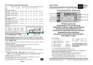
27 Balancing connectors and measuring inputs . . . . . . . . 44<br />
28 Additional sockets on the right side . . . . . . . . . . . . . 46<br />
29 Specifications . . . . . . . . . . . . . . . . . . . . . . . . . . 46<br />
30 Installing the nextConn-<strong>II</strong> module . . . . . . . . . . . . . . . 48<br />
31 Installation of the USB-driver on a PC . . . . . . . . . . . . . 49<br />
Annex Trouble shooting / service questionaire . . . . . . . . . TS, SQ<br />
1