nextGeneration II 2x7-280, 14-280, 14-350 - Schulze Elektronik GmbH
nextGeneration II 2x7-280, 14-280, 14-350 - Schulze Elektronik GmbH nextGeneration II 2x7-280, 14-280, 14-350 - Schulze Elektronik GmbH
14 Page Issue 03.10 Operating instructions Issue 03.10, page nextGeneration II Firmware version V 1.00 and higher nextGeneration II Firmware V 1.00 and higher 35 Fig. 7.6.1 State info 1 (shown: battery 1) State info 2 (device) Fig. 7.6.2 1 state: state: b1 b1 charg. charg. State State info info nextGen nextGen 1 2 progr progr auto2CD auto2CD DeviceType: DeviceType: next next 14-350 14-350 2 3 cycl1 cycl1 + + 2400 2400 - - 2348 2348 Software Software Software Vers: Vers: 1.00 1.00 3 4 cycl2 cycl2 + + 123 123 123 - - 0 0 Device Device Number: Number: Number: 333 333 4 5 Input Input Voltage: Voltage: 13.20V 13.20V 5 6 Inp.Curr.Draw: Inp.Curr.Draw: 5.30A 5.30A 6 7 TakenCapacity: TakenCapacity: 1.61Ah 1.61Ah 1.61Ah 7 8 [mAh] [mAh] Ri Ri = = 317m 317m Schulze Schulze Elektronik Elektronik GmbH GmbH 8 7.7 The first step - the most important settings In Chapter 7.1 you have become familiar with the menu screens and how they are navigated and used; for example, which parameters have to be set in order to charge a Nickel battery properly. If you find you have made so many changes that you no longer understand what is going on, then you may need to carry out a general reset to restore the default settings (Fig. 7.5.2“ setTo:deflt”). Press the button repeatedly until the curve screen is displayed. The screen displays an empty co-ordinate system with “minutes” running from left to right, and the voltage axis running upward. The screen name “Battery 1” is shown in inverse video (black background) at the right-hand margin of the screen, with a vertical column of characters. Before you carry out an initial test by charging the first battery, please examine the upper lines of the screen to check that the status displays match the battery to be charged. Of course, when you operate the unit for the first time many fields will not contain any values, but once you disconnect the battery the old values will be retained for checking purposes until you connect a new pack. In most cases the right choice for Nickel batteries is the fully automatic charge program “autoC”. During the charge process the fully automatic programs measure the battery repeatedly to determine its ability to accept current, and set the required charge current automatically. In practice this means that there is no need to have exact knowledge of the type of Ni-Cd/Ni-MH sintered cell in use, provided that its capacity lies within the permissible range of 100 mAh to several Ah. The only important point is that Ni-Cd cells must ensured a charge current of 2 C and at Ni-MH's a current of 1 C. If you charge a Nickel battery and the automatically set charge current remains below 1C (1C = nominal battery capacity), this generally means that the cells are not - or are no longer - capable of being fast-charged (e.g. high-capacity Ni-MH batteries of AA or AAA cell size). If the pack has a low cell-count, these low charge currents will present problems when the automatic cut-off circuit attempts to detect the “battery full” state, as the voltage peak which develops is not sufficiently pronounced. In this case the only recourse is to charge the pack with a manually set current, or - even better - change to a more suitable battery type; assuming, that there is no problem with the charge lead. The fully automatic programs can only work correctly if the conductors of the charge lead are of adequate cross-section (2.5 mm2 Fig. 7.1 curve screen battery 1 Cell count Batt.type Time (mm:ss) Pack voltage Cycles Program Current Charge quantity Balancing state info - even for charging transmitter and receiver batteries !!) and if the battery cells are soldered (!) together, i.e. they are not simply clamped in a battery box. 7.7.1 If you wish or are obliged to change the parameters relating to Battery 1, press the button again: this calls up a text screen with the title line in inverse video; this is the parameter set-up menu for Battery 1, which should be familiar to you already from Fig. 7.3.1. If you wish to give your Nickel batteries a full charge combined with maximum safety, the following parameters must be set to sensible values before you start charging the pack. TIME, Charge time exceeded If a battery charges for more than 3 hours, we cannot say, that this is quick-charging. If you use autoC program and your battery is not full within 3 hours, autoC did calculate a wrong current (mostly when you charge a receiver pack with the original charge leads). For correct function of the automatic charge current selection a charge lead with 2.5 mm 2 is mandatory. We recommend the use of a charge lead for the flight pack combined with a short (< 50mm) adapter piece to connect your Rx-battery. The short lead of the Rx-battery normally will not affect the performance, but especially mechanical on-off switches with build-in charge sockets are not allowed. Disconnect Pack x Error x77, Charge converter power over maximum Error x3, Battery voltage over maximum (e.g. > 60V on a 10 cell pack) or other nonsense errors These and other unexplainable errors the charger may display, when ... ... connected to a car battery with an operating car battery charger. ... connected to an unsuitable Power Supply. Keep in mind that due to a different environment or situation, even with time consuming tests it may not be possible to find the cause of some error displays. If there are no malfunctions you will still be charged for the time spent on testing! Before you return the device for a check, test it several times connected to a full car battery to ensure the problem has not been caused by reasons mentioned above. EMPTy or RPOL (reverse polarity) - Display during Ni-Cd-Program after about 30s. To delete the memory-effect batteries may have been completely discharged down to 0V (not possible with this device). The charging of these packs is possible, but up to a certain voltage a warning will be displayed. Attention: The warning mentioned above appears if the voltage does not rise fast enough. This could be an indication of reversed polarity, if a completely discharged battery was incorrectly connected. It may even get ‘reverse-charged’. Hint: The nextGenerationII can not detect reversed polarity if a pack is discharged to 0V. It will always start a normal charge cycle, normally ending after 30s with the message reversed polarity (Rpol) or deep discharged (EMPTy), if the battery has not reached a minimum voltage by then. For safety reasons you may have to restart the charge program several times, e.g. when using high capacity cells. • With deep discharged batteries it may take up to ten minutes until the correct number of cells is identified. Disconnect Packs This message will be displayed if batteries are already connected to the charger while connecting it to a power source. The device can not decide by itself whether to select a Ni-Cd- or a PB-program or if Output 1 and 2 may be started uncontrolled. The same message will appear if hardware is defective or if during the program the watchdog detects the microprocessor in a state not foreseen by the software (e.g. due to external interference). Future prospects In the cause of the time we will store more detailed explanations for error messages in the charger which can be accessed by pressing a key. Further details will be described in the corresponding info text "What's new in this version" to update the firmware (Homepage Section C3).
34 Page Issue 03.10 Operating instructions Issue 03.10, page nextGeneration II Firmware version V 1.00 and higher nextGeneration II Firmware V 1.00 and higher 15 20 Protection circuits, error-messages and warnings The nextGenerationII is equipped with various protection and control circuits to monitor car battery voltage, charger temperature, maximum power etc. Exceeding the limits it will interrupt the charge in some cases (e.g. car battery overvoltage). The cause will be displayed and the buzzer will be activated for a short time. The symbols < and > may be displayed. ‘>’ means bigger, ‘= 100 exists then the charger must be disconnected from the car battery/power supply. Hint: All error- or warning-codes which begins (first digit) with "1" indicates that an error at the output number 1 was detected e.t.c. All messages with a leading "9" indicates an overload of the nextGenerationII itself. Error text with code numbers for pack 1, pack 2 Battery voltage below min. 11, 21 Max. Battery voltage exceeded 13, 23 Wrong cell count of Lead- or Lithium battery 17/117, 27/227 Max. Charge current exceeded 161, 261 Max. Discharge current exceeded 162, 262 Max. Charge power of converter exceeded 177, 277 Max. Discharge power of converter exceeded 178, 278 Coupling of battery 1 to battery 2 charge circuit defective (next-14 only) 199 Max. Device input current (primary current) exceeded 961 Max. Device temperature exceeded 981 Car battery voltage exceeded 906 Car battery voltage at minimum 5 Car battery voltage below minimum 904 Charge -time /-quantity /-temperature /-voltage exceeded TIME / QUAN / TEMP / Umax Temperature sensor activated, but disconnected or broken lead Toff Some typical user errors will be listed in more detail, which we strongly recommend you to read before sending the nextGenerationII for a repair as you may simply avoid them: „BalCabXX is wrong“ (Warning 16, Error 116) When the Schulze BalCab connector of a Li-Po or Li-Io battery is configured incomplete (current/ capacity resistor is missing) and is connected to one of the BalCab-connectors then the charger uses the manually configured charge/discharge current for max. 30 seconds - except when the error warning is consciously ignored(!) and confirmed by pressing the button. WARNING: When the BalCab is configured to Li-Fe the charger is unable to detect that the resistor is missing. The nextGenerationII is charging/discharging with the manually configured battery type(!) and current(!). 7.7.2 left - Battery type: e. g.: „bType : NiMH“ 7.7.3 le - Program selection: suggested setting for Ni-Cd and NiMH batteries: „prog. : autoC“ 7.7.4 le - Charge current: „cCurr: x.xx A“. If an automatic program is used (see 7.7.3 left), this parameter should generally be set to the maximum possible charge current, since the automatic circuit continuously varies the current during the charge process. Special hint: Placing a “lid” on the current - especially if it is below 1C for Ni-MH batteries or below 2C for Ni- Cd batteries - may cause the automatic cut-off circuit to fail. 7.7.5 le - Discharge current: We recommend „dCurr: = max. device current" for the autoD selection. 7.7.6 le - Automatic cut-off: Method of working of the automatic cut-off circuit. The setting which works with most batteries is: “cutOf:norm.” for Ni-Cd batteries or “cutOf:sens.” (sensitive) for Ni-MH batteries. 7.7.7 le - Delayed response of the cut-off circuit: Deep-discharged batteries tend to cause a premature cut-off in the first few minutes of a charge process. This menu point prevents the charger checking for “battery full” for several minutes, but please note that it can lead to overheating if a fully charged battery is connected. „delay : 7min“ is fixed at Ni-MH batteries and "autoC". 7.7.2 right - Cell count: Using a Nickel battery the cell count remains at zero, as no battery is connected to the charger. The charger automatically corrects the cell count during the charge or discharge process - repeatedly if necessary. Note: It is certainly possible to correct the cell count manually while a charge or discharge program is in progress, but the cell counts calculated by the unit are generally accurate enough, and are not used when charging Nickel cells in any case. 7.7.3 ri - Setting the C-Rate: By the definition of the Schulze-balancing cables for Lithium batteries the charge current depends on the current resistor soldered in. If you wish to use a higher (or lower) charge current than defined by the configuration of the lead, you can “turn this parameter up or down”. Normally the current multiplication factor is set to 1.0: „cRate: 1.0“. 7.7.4 ri - Charge quantity limitation: An important factor in terms of safety is the maximum charge quantity (battery capacity). You need to estimate how much energy can be charged into your battery. A normal, completely discharged Ni-Cd 2400 mAh cell can generally accept 2400 - 2600 mAh. This means: The maximum charge quantity for flat 2400 cells "quan> 2700" mAh. For Ni-MH cells the basic rule is to set the battery capacity in mAh, plus an addition of about 30%, since the charge quantity limit has a dual function (see Chapter xx). 7.7.5 ri - Charge time limitation: The next safety function is to enter the maximum charge time. The charge time for a fully automatic charge program can only be estimated, as the actual period varies according to the specific cell type. If you do not already know this figure from personal experience, we suggest that you enter a figure at the higher end of the range: Time> 30…45min (for Ni-Cd cells). Please note: If the charge time exceeds three hours, something is fundamentally wrong: either the battery is defective or of high internal resistance (e.g. many AA and AAA cells), the charge leads are too thin, or the connectors are not up to the job. 7.7.6 ri - Over temperature cut-off: The temperature cut-off should be left at OFF: “temp>: OFF” (in particular if the nextConn circuit board is not installed. See Chapter 14 for more details). 7.7.7 ri - Discharge protection diode: This is only required for transmitters fitted with an integral protective discharge diode; the ideal choice is therefore normally: “diode: OFF”. If lithium- or lead-batteries with buildt-in diode are charged, then the batteries are not full despite the „full“ display. The reason is that the nextGenerationII is not able to detect the diode. 7.7.8 ri - Refresh charge: Refresh charge: this should be switched on if you wish to subject your battery to brief discharge pulses during the charging process. It is claimed that tired batteries can be revived more quickly using this method, and it is likely that the principle could be relatively successful with transmitter and receiver batteries, which are almost never discharged completely. However, since the process does not compensate for differences in self-discharge rates between the individual cells of the pack, and since it does not increase the capacity of the cells, this function is purely a matter of taste … refresh charging is switched off in any case when charging Lithium batteries with the Balancer active, as it could have adverse effects. 1 le 2 le 3 le 4 le 5 le 6 le 7 le 8 le Parameter screen battery 1 Fig. 7.7.x Parameter Parameter Set Set battery battery 1 1 1 ri bType bType® bType NiMH NiMH cells cells® cells 0 0 2 ri prog. prog. prog.®autoC prog. autoC cRate cRate® cRate - - 3 ri cCurr cCurr cCurr®3.50A cCurr 3.50A quan> quan>® quan> 500 500 500 4 ri dCurr dCurr dCurr®5.00A dCurr 5.00A time> time>® time> 2h30 2h30 5 ri cutOf cutOf cutOf®sens. cutOf sens. temp> temp>® temp> OFF OFF 6 ri delay delay delay® delay 7min 7min diode diode® diode NO NO 7 ri stora stora stora® stora NO NO refr. refr.® refr. OFF OFF 8 ri
- Page 1 and 2: Page Issue 03.10 nextGeneration II
- Page 3 and 4: 48 Page Issue 03.10 30 Installing t
- Page 5 and 6: 46 Page Issue 03.10 28.5 + - 28.2 +
- Page 7 and 8: 44 Page Issue 03.10 Operating instr
- Page 9 and 10: 42 Page Issue 03.10 Operating instr
- Page 11 and 12: 1 2 3 4 5 6 7 8 1 2 3 4 5 6 7 8 40
- Page 13 and 14: 38 Page Issue 03.10 22.1 Warranty A
- Page 15: 36 Page Issue 03.10 Operating instr
- Page 19 and 20: 32 Page Issue 03.10 nextGeneration
- Page 21 and 22: 30 Page Issue 03.10 nextGeneration
- Page 23 and 24: 28 Page Issue 03.10 nextGeneration
- Page 25 and 26: 26 Page Issue 03.10 nextGeneration
- Page 27 and 28: SQ Page Issue 03.10 nextGeneration
<strong>14</strong><br />
Page Issue 03.10<br />
Operating<br />
instructions<br />
Issue 03.10, page<br />
<strong>nextGeneration</strong> <strong>II</strong> Firmware version V 1.00 and higher<br />
<strong>nextGeneration</strong> <strong>II</strong> Firmware V 1.00 and higher 35<br />
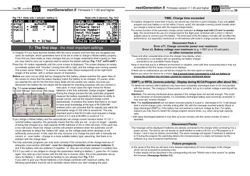
Fig. 7.6.1 State info 1 (shown: battery 1) State info 2 (device) Fig. 7.6.2<br />
1 state: state: b1 b1 charg.<br />
charg.<br />
State State info info nextGen<br />
nextGen 1<br />
2 progr progr auto2CD<br />
auto2CD<br />
DeviceType: DeviceType: next next <strong>14</strong>-<strong>350</strong><br />
<strong>14</strong>-<strong>350</strong> 2<br />
3 cycl1 cycl1 + + 2400 2400 - - 2348<br />
2348<br />
Software Software Software Vers: Vers: 1.00<br />
1.00 3<br />
4 cycl2 cycl2 + + 123 123 123 - - 0<br />
0<br />
Device Device Number: Number: Number: 333<br />
333 4<br />
5<br />
Input Input Voltage: Voltage: 13.20V<br />
13.20V 5<br />
6<br />
Inp.Curr.Draw: Inp.Curr.Draw: 5.30A<br />
5.30A 6<br />
7<br />
TakenCapacity: TakenCapacity: 1.61Ah 1.61Ah<br />
1.61Ah 7<br />
8 [mAh] [mAh] Ri Ri = = 317m<br />
317m<br />
<strong>Schulze</strong> <strong>Schulze</strong> <strong>Elektronik</strong> <strong>Elektronik</strong> <strong>GmbH</strong><br />
<strong>GmbH</strong> 8<br />
7.7 The first step - the most important settings<br />
In Chapter 7.1 you have become familiar with the menu screens and how they are navigated and<br />
used; for example, which parameters have to be set in order to charge a Nickel battery properly.<br />
If you find you have made so many changes that you no longer understand what is going on, then<br />
you may need to carry out a general reset to restore the default settings (Fig. 7.5.2“ setTo:deflt”).<br />
Press the button repeatedly until the curve screen is displayed. The screen displays an empty<br />
co-ordinate system with “minutes” running from left to right, and the voltage axis running upward.<br />
The screen name “Battery 1” is shown in inverse video (black background) at the right-hand<br />
margin of the screen, with a vertical column of characters.<br />
Before you carry out an initial test by charging the first battery, please examine the upper lines of<br />
the screen to check that the status displays match the battery to be charged. Of course, when<br />
you operate the unit for the first time many fields will not contain any values, but once you<br />
disconnect the battery the old values will be retained for checking purposes until you connect a<br />
new pack. In most cases the right choice for Nickel<br />
batteries is the fully automatic charge program “autoC”.<br />
During the charge process the fully automatic programs<br />
measure the battery repeatedly to determine its ability to<br />
accept current, and set the required charge current<br />
automatically. In practice this means that there is no need<br />
to have exact knowledge of the type of Ni-Cd/Ni-MH<br />
sintered cell in use, provided that its capacity lies within the<br />
permissible range of 100 mAh to several Ah. The only<br />
important point is that Ni-Cd cells must ensured a charge<br />
current of 2 C and at Ni-MH's a current of 1 C.<br />
If you charge a Nickel battery and the automatically set charge current remains below 1C (1C =<br />
nominal battery capacity), this generally means that the cells are not - or are no longer - capable<br />
of being fast-charged (e.g. high-capacity Ni-MH batteries of AA or AAA cell size). If the pack has<br />
a low cell-count, these low charge currents will present problems when the automatic cut-off<br />
circuit attempts to detect the “battery full” state, as the voltage peak which develops is not<br />
sufficiently pronounced. In this case the only recourse is to charge the pack with a manually set<br />
current, or - even better - change to a more suitable battery type; assuming, that there is no<br />
problem with the charge lead.<br />
The fully automatic programs can only work correctly if the conductors of the charge lead are of<br />
adequate cross-section (2.5 mm2 Fig. 7.1 curve screen battery 1<br />
Cell count Batt.type Time (mm:ss) Pack voltage<br />
Cycles Program Current Charge quantity<br />
Balancing state info<br />
- even for charging transmitter and receiver batteries !!)<br />
and if the battery cells are soldered (!) together, i.e. they are not simply clamped in a battery box.<br />
7.7.1 If you wish or are obliged to change the parameters relating to Battery 1, press the button<br />
again: this calls up a text screen with the title line in inverse video; this is the parameter set-up<br />
menu for Battery 1, which should be familiar to you already from Fig. 7.3.1.<br />
If you wish to give your Nickel batteries a full charge combined with maximum safety, the<br />
following parameters must be set to sensible values before you start charging the pack.<br />
TIME, Charge time exceeded<br />
If a battery charges for more than 3 hours, we cannot say, that this is quick-charging. If you use autoC<br />
program and your battery is not full within 3 hours, autoC did calculate a wrong current (mostly when<br />
you charge a receiver pack with the original charge leads).<br />
For correct function of the automatic charge current selection a charge lead with 2.5 mm 2 is mandatory.<br />
We recommend the use of a charge lead for the flight pack combined with a short (< 50mm)<br />
adapter piece to connect your Rx-battery. The short lead of the Rx-battery normally will not affect the<br />
performance, but especially mechanical on-off switches with build-in charge sockets are not allowed.<br />
Disconnect Pack x<br />
Error x77, Charge converter power over maximum<br />
Error x3, Battery voltage over maximum (e.g. > 60V on a 10 cell pack)<br />
or other nonsense errors<br />
These and other unexplainable errors the charger may display, when ...<br />
... connected to a car battery with an operating car battery charger.<br />
... connected to an unsuitable Power Supply.<br />
Keep in mind that due to a different environment or situation, even with time consuming tests it may not<br />
be possible to find the cause of some error displays.<br />
If there are no malfunctions you will still be charged for the time spent on testing!<br />
Before you return the device for a check, test it several times connected to a full car battery to<br />
ensure the problem has not been caused by reasons mentioned above.<br />
EMPTy or RPOL (reverse polarity) - Display during Ni-Cd-Program after about 30s.<br />
To delete the memory-effect batteries may have been completely discharged down to 0V (not possible<br />
with this device). The charging of these packs is possible, but up to a certain voltage a warning will be<br />
displayed.<br />
Attention: The warning mentioned above appears if the voltage does not rise fast enough. This could<br />
be an indication of reversed polarity, if a completely discharged battery was incorrectly connected. It<br />
may even get ‘reverse-charged’.<br />
Hint: The <strong>nextGeneration</strong><strong>II</strong> can not detect reversed polarity if a pack is discharged to 0V. It will always<br />
start a normal charge cycle, normally ending after 30s with the message reversed polarity (Rpol) or<br />
deep discharged (EMPTy), if the battery has not reached a minimum voltage by then. For safety<br />
reasons you may have to restart the charge program several times, e.g. when using high capacity<br />
cells.<br />
• With deep discharged batteries it may take up to ten minutes until the correct number of cells is<br />
identified.<br />
Disconnect Packs<br />
This message will be displayed if batteries are already connected to the charger while connecting it to a<br />
power source. The device can not decide by itself whether to select a Ni-Cd- or a PB-program or if<br />
Output 1 and 2 may be started uncontrolled. The same message will appear if hardware is defective<br />
or if during the program the watchdog detects the microprocessor in a state not foreseen by the<br />
software (e.g. due to external interference).<br />
Future prospects<br />
In the cause of the time we will store more detailed explanations for error messages in the charger<br />
which can be accessed by pressing a key.<br />
Further details will be described in the corresponding info text "What's new in this version" to update<br />
the firmware (Homepage Section C3).


