nextGeneration II 2x7-280, 14-280, 14-350 - Schulze Elektronik GmbH
nextGeneration II 2x7-280, 14-280, 14-350 - Schulze Elektronik GmbH
nextGeneration II 2x7-280, 14-280, 14-350 - Schulze Elektronik GmbH

You also want an ePaper? Increase the reach of your titles
YUMPU automatically turns print PDFs into web optimized ePapers that Google loves.
36<br />
Page Issue 03.10<br />
Operating<br />
instructions<br />
Issue 03.10, page<br />
<strong>nextGeneration</strong> <strong>II</strong> Firmware version V 1.00 and higher<br />
<strong>nextGeneration</strong> <strong>II</strong> Firmware V 1.00 and higher 13<br />
21 Important notes<br />
21.1 Charging leads are only to be connected to the appropriate Outputs.<br />
Cross wiring between Outputs may cause short circuits and damage the device and the<br />
batteries (even may cause melting or explosion!).<br />
21.2 Transmitters are often protected against discharge by a diode. For quick charge this<br />
feature needs to be disabled (see Tx-Manual) or must be charged with the w.Diode<br />
charge option (see CutOff menu).<br />
To avoid possible damage inside the Tx, the charge current must not exceed 1.2A<br />
(Graupner mc-18/20). Watch the charge current when using an automatic program.<br />
The resistance of the printed circuit board may cause the microprocessor to select a<br />
charge current too low for safe peak detection.<br />
When in doubt: Choose manual selection.<br />
Warning: with large-capacity batteries it is not possible to set a charge current of 1 C or<br />
2 C as required for reliable Peak termination, and for this reason we strongly advise<br />
you not to charge the transmitter battery in the transmitter!<br />
21.3 A common cause for insufficient charge currents in automatic mode for Nickel<br />
batteries are unsuitable charge leads. The automatic charge current calculation is<br />
based on the measurement of the internal resistance of the connected battery. The<br />
lower the internal resistance, the higher the possible charge current.<br />
As the charger can only measure the total resistance (internal resistance+ resistance of<br />
the leads + resistance of the connectors), for correct calculation of the charge current it<br />
is essential to keep the additional resistance at a minimum by using charging leads<br />
with adequate cross sections (2.5mm2 , also for Rx-batteries!), high quality (gold)<br />
connectors, and a maximum length of 75 cm.<br />
When using thin charging leads and/or on-off switches with build-in charging sockets on<br />
low voltage batteries, the additional resistance of the connectors and cables could be<br />
higher than the actual battery resistance. In this case the automatic charge current<br />
would be less than half of what it should be! In such cases manual current selection is<br />
recommended. The microprocessor will also consider the condition of the cells when<br />
calculation the charge current in automatic modes.<br />
21.4 Don’t be amazed if your battery packs seem to absorb lower currents in automatic<br />
programs during the winter months - a cold cell does not perform like a warm one.<br />
21.5 If the charger technically can not provide the charge current manually selected or<br />
automatically calculated (see example above, or e.g. 6.0A at 30 cells), a "*" will appear<br />
between voltage and current values on the display. In this case the actual charge<br />
current will be displayed.<br />
21.6 During the measuring phases (a "!" appears between voltage and current figures),<br />
some function keys are blocked. They are also inoperative when the charger has<br />
noticed a drop in the charge voltage, so that peak detection will not be disturbed.<br />
The cut-off automatic can be monitored: it takes several, closely followed voltage drops<br />
before the charge on Output 1 is terminated.<br />
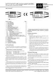
7.5 The left button group includes a button marked .<br />
7.5.1 Pressing the button once calls up the parameter screen 7.5.1, which contains the<br />
device settings described below.<br />
For example, this menu segment includes settings which<br />
Device parameters 1 Fig. 7.5.1<br />
define how you wish the charger to behave when a Parameter Parameter Parameter Set Set 1 1 nextGen<br />
nextGen 1<br />
battery is fully charged.<br />
fan fan ® OFF OFF curr> curr>®* curr> * 16A 16A<br />
16A 2<br />
At this point you can also restrict the charger’s power light light®blink light blink powr> powr>® powr> 150W<br />
150W 3<br />
consumption, so as to avoid overloading mains PSUs buzzr buzzr® buzzr ON ON ON batt< batt temp>®*60°C<br />
temp> *60°C<br />
5<br />
Not least of these menu functions is the ability to dQuan dQuan® dQuan OFF OFF melod melod® melod 0, 0, 0, 0<br />
0 6<br />
enter your name.<br />
name name ®>new< >new< passw passw®>new<<br />
passw >new<<br />
7<br />
<strong>Schulze</strong> <strong>Schulze</strong> <strong>Schulze</strong> <strong>Elektronik</strong> <strong>Elektronik</strong> <strong>GmbH</strong><br />
<strong>GmbH</strong> 8<br />
The meaning of all the parameters is described in<br />
Chapter 23.<br />
7.5.2 Pressing the button a second time calls up the parameter screen 7.5.2, which primarily<br />
contains set-up parameters for Lithium batteries<br />
Device parameters 2 Fig. 7.5.2<br />
(upper and lower voltage limit values). The charger’s<br />
funnel-shaped balancing function "balan:autom" is Parameter Parameter Set Set 2 2 nextGen<br />
nextGen 1<br />
well known from other <strong>Schulze</strong> balancers.<br />
value value®tabul value tabul menu menu ®small small<br />
2<br />
start start®autom start autom setTo setTo®deflt<br />
setTo deflt<br />
3<br />
Note: The function to parallel the charging outputs b1+b2<br />
balan balan®autom balan autom carBt carBt®reset<br />
carBt reset<br />
4<br />
is only available in the next-<strong>14</strong>-XXX.<br />
uLiPo uLiPo®*3000 uLiPo *3000 ULiPo ULiPo®*4200<br />
ULiPo *4200<br />
5<br />
Note: the asterisks “*” which precede the set-up values in uLiIo uLiIo®*2700 uLiIo *2700 ULiIo ULiIo®*4100<br />
ULiIo *4100<br />
6<br />
the right-hand columns of Figs. 7.5.1 and 7.6.1 mean uLiFe uLiFe®*2000 uLiFe *2000 ULiFe ULiFe®*3650<br />
ULiFe *3650<br />
7<br />
that the user has set the recommended parameters b1+b2 b1+b2® b1+b2 OFF OFF UpCas UpCas® UpCas OFF 8<br />
(suggested values) for the menu point in question.<br />
7.5.3 If you press the button repeatedly, you alternate between the two device parameter<br />
screens, i.e. Figs. 7.5.1 and 7.5.2. In the next-<strong>14</strong>-<strong>350</strong> a third parameter screen is shown to set<br />
the real time clock and to read out / erase the internal curve memory.<br />
7.5.4 You can move to the Power-On screen (Fig. 1.2) by pressing the button, to the battery<br />
curve screen (Fig. 7.2.1) by pressing , and to the Battery 2 curve screen by pressing .<br />
7.6 When the screen is displaying a curve rather than one of the parameter displays, the <br />
button (actually) has no function. For this reason we have used the button in this case for<br />
displaying screens with additional information content relating to the current charge /<br />
discharge process for Battery 1 and Battery 2, or the state of the device.<br />
7.6.1 Pressing when one of the two curve screens (Battery 1 or Battery 2) is on the screen<br />
causes line 1 to show the status for the battery (b1 ready, b2 charging), the current program for<br />
the battery, the number of cycles for the battery (up to the maximum number of five cycles) and<br />
the internal resistance of the battery in the bottom line (see also Fig. 7.6.2 on the next page).<br />
Note: The info screens to display data for Battery 1 or 2 are changed by pressing or .<br />
7.6.2 Pressing two times when one of the two curve screens (Battery 1 or Battery 2) is<br />
displayed calls up information about the device and the current “power supply situation” (see also<br />
Fig. 7.6.2 on the next page).<br />
7.6.3 Pressing repeatedly toggles between the screens 7.6.1 and 7.6.2 and the curve screen<br />
previously displayed. When a balancing connector of a battery is plugged in, then the cell<br />
voltages are displayed at the first push on the button (Fig. 15.5 on page 22).<br />
The display can be alternated between cell 1-7 and 7-<strong>14</strong> (= 1-7 of bat.2) by pressing or .<br />
Pressing the button takes you to the last curve screen displayed, while the or <br />
buttons take you directly to the corresponding curve screens.