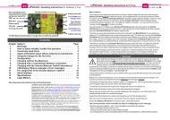
nextGeneration II 2x7-280, 14-280, 14-350 - Schulze Elektronik GmbH
nextGeneration II 2x7-280, 14-280, 14-350 - Schulze Elektronik GmbH
nextGeneration II 2x7-280, 14-280, 14-350 - Schulze Elektronik GmbH

You also want an ePaper? Increase the reach of your titles
YUMPU automatically turns print PDFs into web optimized ePapers that Google loves.
38<br />
Page Issue 03.10<br />
22.1 Warranty<br />
All <strong>Schulze</strong> devices are carefully checked<br />
and tested before dispatch.<br />
If you have a complaint, send the unit back<br />
to us with a clear description of the fault.<br />
A message such as "doesn't work<br />
properly" or "software error" doesn't help<br />
us much!<br />
For all supply of warranty services our<br />
Terms of Sale and Supply are applicable<br />
(see <strong>Schulze</strong> Homepage).<br />
One further note:<br />
If a problem arises with any <strong>Schulze</strong><br />
product, send it directly to us without<br />
interfering with it in any way.<br />
Changes or extensions of the device can<br />
lead to additional costs if these impede<br />
or prevent services.<br />
Non-suitable components will be<br />
replaced or build back to the delivered<br />
condition at the owners expense without<br />
any consultation.<br />
This ensures that we can repair the unit<br />
quickly, pick up warranty faults without<br />
any dispute, and keep costs to a<br />
minimum.<br />
You can also be sure that we will fit<br />
genuine replacement parts which will<br />
work properly in your unit. Unfortunately<br />
we have had bad experience with thirdparty<br />
Service Centres which claim<br />
technical competence. Note also that any<br />
out-side interference with our products<br />
invalidates the warranty. Incompetent<br />
attempts at repair can cause further<br />
damage. We often find it impossible to<br />
estimate the repair cost of devices in<br />
such condition, and in certain circumstances<br />
we are then obliged to decline to<br />
repair it altogether.<br />
Operating<br />
instructions<br />
Issue 03.10, page<br />
<strong>nextGeneration</strong> <strong>II</strong> Firmware version V 1.00 and higher<br />
<strong>nextGeneration</strong> <strong>II</strong> Firmware V 1.00 and higher 11<br />
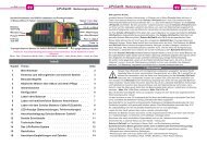
22 Legal matters<br />
22.2 CE approval<br />
All <strong>Schulze</strong> devices satisfy all relevant and<br />
mandatory EC directives:<br />
These are the<br />
EMF directive 2004/108/EG<br />
The product has been tested to meet the<br />
following basic technical standards:<br />
Interference radiation:<br />
DIN EN 550<strong>14</strong>-1: 2010-02<br />
Interference susceptibility:<br />
DIN EN 550<strong>14</strong>-2: 2009-06<br />
You are the owner of a product whose design<br />
and construction fulfil the safety aims of the<br />
EC for the safe operation of devices.<br />
The approval procedure includes a test of<br />
interference radiation, i.e. of interference<br />
generated by the charger. This charger has<br />
been tested under practical conditions at<br />
maximum load current and with a large<br />
number of cells, and remains within the<br />
interference limits.<br />
A less stringent test would be, for example,<br />
to measure interference levels at a low<br />
charge current. In such cases the charger<br />
would not produce its maximum interference<br />
level.<br />
The procedure also includes also a test of<br />
interference susceptibility, i.e. the extent to<br />
which the device is vulnerable to interference<br />
from other devices. The test involves<br />
subjecting the charger to RF signals similar<br />
to those produced by an RC transmitter or a<br />
radio telephone.<br />
Cell voltage info - Chapter/Fig. 15.5<br />
b1: b1: Ucell Ucell Udiff Udiff Ri/m<br />
Ri/m 1<br />
2<br />
3<br />
c5: c5: 3160 3160 0 0 mV mV 6<br />
6 4<br />
c4: c4: 2276 2276 384 384 mV mV 8 8<br />
8 5<br />
c3: c3: 3078 3078 82 82 mV mV 7<br />
7 6<br />
c2: c2: 3048 3048 112 112 mV mV 7 7<br />
7 7<br />
c1: c1: 3110 3110 50 50 mV mV 6<br />
6 8<br />
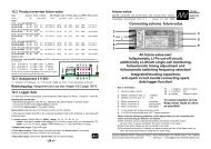
7.1 The first step - the screens<br />
7.1 Take the <strong>nextGeneration</strong><strong>II</strong> out of the packaging.<br />
See Chapter 2: General Remarks and Precautions. Lack of air circulation may cause overheating.<br />
7.1.1 Connect the <strong>nextGeneration</strong><strong>II</strong> to the 12 volt power source car battery.<br />
Note: Do not connect battery packs to the charger during this procedure. First try to get a good<br />
contact to the car battery terminals, otherwise you may not get the power-On screen on the<br />
display. In this case disconnect the charger immediately from the car battery and retry after<br />
about 5 seconds.<br />
Power-On screen Fig. 7.1.2<br />
7.1.2 Initially the liquid crystal screen very briefly shows<br />
<strong>nextGeneration</strong> <strong>nextGeneration</strong> <strong>nextGeneration</strong> <strong>14</strong>-<strong>350</strong><br />
<strong>14</strong>-<strong>350</strong><br />
the software version of the display processor; the<br />
screen backlighting is switched on and displays the<br />
V V 1.00 1.00 1.00 english<br />
english<br />
english<br />
PowerOn menu screen along with the type designa-<br />
Owner<br />
Owner<br />
tion “<strong>nextGeneration</strong><strong>II</strong> xx-yyy” (exact type designa-<br />
<strong>Schulze</strong> <strong>Schulze</strong> <strong>Elektronik</strong> <strong>Elektronik</strong> <strong>GmbH</strong><br />
<strong>GmbH</strong><br />
tion), the ms logo, the software version and the<br />
Mo Mo 25.03.10 25.03.10 25.03.10 23:06:27<br />
23:06:27<br />
owner’s name. Line 6 shows date and time (only on<br />
Menüsprache Menüsprache ändern ändern in in<br />
in<br />
next-<strong>14</strong>-<strong>350</strong> types). At this point you can also switch<br />
Sprache Sprache = = deutsch deutsch deutsch <br />
<br />
to the second menu language, if you wish; simply<br />
follow the on-screen instructions (see chapter / figure 23.2).<br />
If YOUR language is not available on the charger please check if it is available on our homepage or our<br />
USB-stick (in preparation) and install it on your charger. Follow the help text of the installation program.<br />
7.2 The <strong>nextGeneration</strong><strong>II</strong> features nine operating buttons. The three buttons , and<br />
, which constitute the Parameter button group, are<br />
used to move to the battery and device parameter<br />
battery 1 curve screen Fig. 7.2.1<br />
screens.<br />
5LiPo 5LiPo 00:00 00:00 0.00V 0.00V b 1<br />
7.2.1 Selecting or initially brings up the graphic<br />
screens which display the charge / discharge voltage<br />
curves and the most important set parameters -<br />
shown in the first two lines of the screen (pict. right).<br />
7.2.1.1 If the curve screen for Battery 1 is on the screen,<br />
you can switch directly to the curve screen for Battery<br />
2 (and vice versa) by pressing .<br />
fix_C fix_C (3.20A) (3.20A) 0mAh 0mAh a<br />
8V 8V<br />
t<br />
t<br />
ready<br />
ready<br />
1<br />
1 1 2<br />
2<br />
2V 2V 1234 1234 1234 5 5 t<br />
t<br />
2<br />
3<br />
4<br />
5<br />
6<br />
7<br />
8<br />
7.2.1.2 If one of the two curve screens is displayed (Battery 1 or Battery 2) you can press (=<br />
) to access status displays for these batteries which are not included in the curve screen<br />
(Chapter 1.4). Pressing the button again calls up information about the state of the power<br />
supply (e.g. the car battery) (Chapter 1.5).<br />
battery 1 parameter screen Fig. 7.3.1<br />
7.3.1 For example, if the curve screen for Battery 1 is<br />
displayed (Fig. 2.1), another press on switches to<br />
the parameter settings for Battery 1 (and vice versa).<br />
The information for all parameters are shown on a<br />
single screen, and is therefore slightly compressed,<br />
but this is in response to requests from many users<br />
that all the parameters should be visible without<br />
having to switch between screen displays. When a<br />
combi-program is in use, the circle shows the number<br />
of cycles.<br />
Parameter Parameter Set Set battery battery 1<br />
1<br />
bType bType® bType LiPo LiPo cells cells® cells +b +b 5 5<br />
5<br />
prog. prog.®fix_L prog. fix_L cRate cRate® cRate 1.0<br />
1.0<br />
cCurr cCurr®3.50A cCurr 3.50A quan> quan>® quan> <strong>350</strong>0 <strong>350</strong>0<br />
<strong>350</strong>0<br />
dCurr dCurr dCurr®5.00A dCurr dCurr 5.00A time> time>® time> 1h30<br />
1h30<br />
cutOf cutOf®v-max cutOf v-max temp> temp>® temp> OFF<br />
OFF<br />
delay delay® delay 2min 2min 2min diode diode® diode NO NO<br />
NO<br />
stora stora® stora NO NO NO refr. refr.® refr. OFF<br />
OFF<br />
1<br />
2<br />
3<br />
4<br />
5<br />
6<br />
7<br />
8<br />
Remark: You also can select an option in the device parameter set 1 with "wide" screens (chapter 23.<strong>14</strong>).<br />
Setting the „cRate“: By the definition of the <strong>Schulze</strong>-balancing cables the charge current<br />
depends on the current resistor soldered in. If you wish to use a higher (or lower) charge current<br />
than the defined by the configuration of the cable, you can “turn this parameter up or down”.<br />
1<br />
2<br />
3<br />
4<br />
5<br />
6<br />
7<br />
8