nextGeneration II 2x7-280, 14-280, 14-350 - Schulze Elektronik GmbH
nextGeneration II 2x7-280, 14-280, 14-350 - Schulze Elektronik GmbH
nextGeneration II 2x7-280, 14-280, 14-350 - Schulze Elektronik GmbH

Create successful ePaper yourself
Turn your PDF publications into a flip-book with our unique Google optimized e-Paper software.
Page Issue 03.10<br />
<strong>nextGeneration</strong> <strong>II</strong> Firmware V 1.00 and higher<br />
<strong>Schulze</strong> <strong>Elektronik</strong> <strong>GmbH</strong> • Prenzlauer Weg 6 • 64331 Weiterstadt • Fon: +49-6150-1306-5, Fax: 1306-99<br />
www.schulze-elektronik-gmbh.com • Germany • hotline@schulze-elektronik-gmbh.com<br />
<strong>nextGeneration</strong> <strong>II</strong> Firmware version V 1.00 and higher<br />
Instruction manual<br />
<strong>nextGeneration</strong> <strong>II</strong><br />
<strong>2x7</strong>-<strong>280</strong>, <strong>14</strong>-<strong>280</strong>, <strong>14</strong>-<strong>350</strong><br />
Firmware version V 1.00 and higher<br />
Operating<br />
instructions<br />
Issue 03.10, page<br />
Microprocessor controlled<br />
Quick charger, Discharger, Capacity tester<br />
Battery conditioner<br />
for sealed Ni-Cd-, Ni-MH-, Lead- (Lead-Acid, Lead-Gel)<br />
and Lithium-Batteries (Li-FePO4, Li-Ion, Li-Po)<br />
• Graphical display of charge voltage<br />
• Data transfer interface for personal computer (PC)<br />
• „Full“ display by buzzer<br />
• Integrated electronic discharge load<br />
• Internal temperature controlled fan
Page Issue 03.10<br />
Operating<br />
instructions<br />
Issue 03.10, page<br />
<strong>nextGeneration</strong> <strong>II</strong> Firmware version V 1.00 and higher<br />
<strong>nextGeneration</strong> <strong>II</strong> Firmware V 1.00 and higher 49<br />
31 Installation of the USB-driver on the PC<br />
(for all who are not so familiar with the Windows operating system)<br />
31.1 Installation of the USB driver<br />
If you like to display the online-charge/discharge-data (which are available on the USB-port of the<br />
<strong>nextGeneration</strong> <strong>II</strong> ) via Akkusoft as well as installing a firmware update then you have to install the<br />
USB driver on your PC first (available on our Homepage in section C4 - schulze-next-<strong>II</strong>.inf).<br />
31.1.1 Windows operating systems initially ask the user at the moment when you have connected the<br />
USB-port of a charger (or USB-adapter) with the USB-slot on your computer where to find the fitting<br />
driver (for the <strong>nextGeneration</strong> <strong>II</strong> it is the schulze-next-<strong>II</strong>.inf file). Set the desired file-path to the<br />
downloaded file.<br />
If you have aborted the hardware installation assistant you can start it again by a right-click on MyComputer<br />
(“Arbeitsplatz” in german) -> Properties, -> Hardware, -> Device Manager, -> Other devices, -><br />
<strong>Schulze</strong> <strong>nextGeneration</strong><strong>II</strong> then right click on -> update driver and start again (or similar text).<br />
It is not necessary that the charger is connected to any power supply - it is powered via the USB-cable.<br />
31.1.2 When the driver is successfully installed and that you will be able to receive and store battery data<br />
with a normal terminal program or an elder version of the Akkusoft - then you have to look on which<br />
COM port the operating system has installed your USB-device (see chapter 31.1.3). The latest<br />
Akkusoft offers in the connection -> property -> connect with menu very comfortable to make a<br />
selection on "<strong>Schulze</strong> <strong>nextGeneration</strong><strong>II</strong>", so that it is not necessary to perform chapter 31.1.3.<br />
31.1.3 On Windows XP you can establish the number of the COM port occupied by the driver by rightclicking<br />
on the workplace symbol of your PC; click or double-click on Properties, Hardware, Device<br />
Manager, Ports (COM and LPT). You will find a COM port with the name "<strong>Schulze</strong> <strong>nextGeneration</strong><strong>II</strong>".<br />
Windows normally installs the device on “COM3” or higher.<br />
Important note:<br />
This connection is only displayed when the charger or our USB-adapter is connected to the USB port<br />
of the PC!<br />
Also important:<br />
If you use more than one <strong>nextGeneration</strong><strong>II</strong> then the driver will install for each <strong>nextGeneration</strong><strong>II</strong><br />
charger an additional USB port number.<br />
PS: These proceedings are not specific for the Akkusoft or any connected charger, but is specific for<br />
installing a driver on the Windows operating system.<br />
31.2 Setting the COM port e.g. in the “Akkusoft” analysis program.<br />
31.2.1 Open Akkusoft. Open the pull-down menu entitled “Connection”, then click on “Properties”.<br />
Select the port identified under section 31.1.2 / 31.1.3, then click on OK.<br />
31.2.2 Checking the function of the COM interface (in the Akkusoft analysis program).<br />
• Click on “Info”, then on “Online Info”. An information window opens, displaying the communication<br />
between the charger and the PC.<br />
• Now connect the charger to the power supply, or – if you have already done that – connect a battery<br />
to the charger.<br />
• The interface data appears in the “Online Data” window mentioned above.<br />
31.3 Firmware update<br />
When this test (section 31.2.3) was successful then you also can upgrade the firmware via this USB-Link.<br />
Click on “Tools” and then “FirmwareUpdate”.<br />
But first you have to select the fitting file type for the <strong>nextGeneration</strong> <strong>II</strong> (file ending .nx2).<br />
Follow the instructions on the update-screens.<br />
Note: Contrary to chapter 31.1.1 it is not(!) allowed with the firmware update that the charger is connected<br />
to any power supply - it must be exclusively powered via the USB-cable.
48<br />
Page Issue 03.10<br />
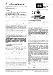
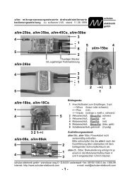
30 Installing the<br />
nextConn-<strong>II</strong> module<br />
The next-XX-XXX-“eco“ types are<br />
supplied as standard without nextConn-<br />
<strong>II</strong> module. The nextConn-<strong>II</strong> module can<br />
very easily be installed if required.<br />
Note: Opposite figures similar.<br />
30.1 Opening the case<br />
Undo the six cross-point screws (1 – 6)<br />
and remove the bottom case section.<br />
30.2 Installing the nextConn-<strong>II</strong> module<br />
and the side panel insert<br />
31.2.1 Remove the side panel (8) and<br />
replace it with the new, perforated panel.<br />
You may find that the side panel comes<br />
away together with the bottom case<br />
section.<br />
30.2.2 Locate the ten holes in the<br />
smooth underside of the nextConn-<strong>II</strong><br />
module (9) and position them directly<br />
over the ten connector pins (7) mounted<br />
on the large base circuit board. Don’t<br />
use force! The nextConn-<strong>II</strong> module will<br />
automatically (!) fall into place on the<br />
base circuit board if correctly positioned.<br />
Check that the two nylon screws engage<br />
in the corresponding holes in the base<br />
circuit board.<br />
30.3 Pressing the nextConn-<strong>II</strong> module<br />
into place<br />
Press the nextConn module down<br />
gently as far as it will go, to ensure that<br />
the connectors make good contact.<br />
The tips of the connector pins (7) must<br />
be exposed at the top of the ten-pin<br />
socket (10).<br />
30.4 Closing the case<br />
Position the bottom case section<br />
accurately on the top case section,<br />
taking care to engage the side panels<br />
correctly.<br />
Re-fit the screws (1 – 6); take care not<br />
to over-tighten them.<br />
Note: the nextConn-<strong>II</strong> module is not<br />
screwed to the base circuit board.<br />
Nevertheless, it is held in place securely<br />
by the moulded-in supports (13 – 16) and<br />
the two nylon screws (11 – 12) when the<br />
case components are screwed together.<br />
<strong>nextGeneration</strong> <strong>II</strong> Firmware V 1.00 and higher<br />
Fig.<br />
31.1<br />
Fig. 31.2<br />
12<br />
9<br />
Fig.<br />
31.3<br />
1 2<br />
3 4<br />
5 6<br />
10<br />
8<br />
8<br />
13<br />
7<br />
11<br />
<strong>14</strong><br />
7<br />
16<br />
15<br />
12<br />
Fig. 31.4<br />
8<br />
<strong>nextGeneration</strong> <strong>II</strong> Firmware version V 1.00 and higher<br />
Contents<br />
Operating<br />
instructions<br />
Issue 03.10, page<br />
Chapter Topic Page<br />
1 General information . . . . . . . . . . . . . . . . . . . . . . 2<br />
2 General remarks and precautions . . . . . . . . . . . . . . 3<br />
3 Commonly used terms . . . . . . . . . . . . . . . . . . . . 5<br />
4 Useful information about batteries and maintenance . . . . 6<br />
5 Mounting instructions CE ring . . . . . . . . . . . . . . . . 10<br />
6 Functions . . . . . . . . . . . . . . . . . . . . . . . . . . . 10<br />
7 The first step . . . . . . . . . . . . . . . . . . . . . . . . . 11<br />
8 Nickel- (Ni-Cd/Ni-MH) battery programs . . . . . . . . . . . 16<br />
9 Lead- (Pb = lead-acid/lead-gel) battery programs . . . . . . 19<br />
10 Lithium- (Li-Fe, Li-Ion, Li-Po) battery programs . . . . . . . 20<br />
11 Charging/discharging of Ni-Cd / Ni-MH transmitter batteries 21<br />
12 Hints (plug-in proceeding / charging/discharging of 1-3 cells / storing) . 21<br />
13 Automatic Cut-off Circuit . . . . . . . . . . . . . . . . . . . . 22<br />
<strong>14</strong> Monitoring and safety facilities . . . . . . . . . . . . . . . . 23<br />
15 Monitoring functions on LCD-panel . . . . . . . . . . . . . 27<br />
16 Special adjustments (inclusively Motor Run-In) . . . . . . . . 28<br />
17 Writing/reading (internal) customer configurations . . . . . 32<br />
18 Writing/reading of external configurations . . . . . . . . . . 32<br />
19 Additional sockets (on the right side) . . . . . . . . . . . . . 33<br />
20 Protection circuits, error-messages and warnings . . . . . 34<br />
21 Important notes . . . . . . . . . . . . . . . . . . . . . . . . . 36<br />
22 Legal matters . . . . . . . . . . . . . . . . . . . . . . . . . . 38<br />
23 Menu overview . . . . . . . . . . . . . . . . . . . . . . . . 39<br />
24 Standard ready made configurations . . . . . . . . . . . . . 42<br />
25 Standard setup charge- and discharge programs . . . . . . 42<br />
26 Data format PC interface . . . . . . . . . . . . . . . . . . . 43<br />
27 Balancing connectors and measuring inputs . . . . . . . . 44<br />
28 Additional sockets on the right side . . . . . . . . . . . . . 46<br />
29 Specifications . . . . . . . . . . . . . . . . . . . . . . . . . . 46<br />
30 Installing the nextConn-<strong>II</strong> module . . . . . . . . . . . . . . . 48<br />
31 Installation of the USB-driver on a PC . . . . . . . . . . . . . 49<br />
Annex Trouble shooting / service questionaire . . . . . . . . . TS, SQ<br />
1
2<br />
Page Issue 03.10<br />
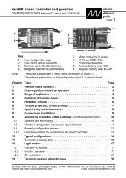
Fan input<br />
(KEEP CLEAR!)<br />
pos (+)<br />
Battery 1<br />
neg (-)<br />
Batt.1 parameters<br />
and curve screen1<br />
Device parameters<br />
Escape* (break off)<br />
Balancer-Adapterconnector<br />
for<br />
<strong>Schulze</strong><br />
BalAd-SE4-7-<strong>14</strong><br />
or<br />
BalAd-SE4x7<br />
(*) For long time users of the <strong>nextGeneration</strong> 1 the keys<br />
and can be interchanged. See chapter 21.12<br />
<strong>nextGeneration</strong> <strong>II</strong> Firmware V 1.00 and higher<br />
1 General information<br />
Fan input/output<br />
(KEEP CLEAR!)<br />
(+) pos<br />
Battery 2<br />
(-) neg<br />
Batt.2 parameters*<br />
and curve screen2<br />
Cursor movement,<br />
Value selection<br />
Enter (accept) or<br />
Information<br />
about the connected<br />
batteries, charger<br />
characteristics and<br />
car battery volts/amps.<br />
Charge display = duration,<br />
full / empty = blinking light,<br />
deaktivation = chapt. 16.7<br />
8-pin EH male connector to connect<br />
2s - 7s balancing adapters<br />
Congratulations! With the <strong>nextGeneration</strong><strong>II</strong> you have purchased a top of the line product made in<br />
Germany. Reliable SMD technology, outstanding performance and flexibility and last but not least<br />
their easy handling and the new technological features you will have a lot of fun with it. By using the<br />
up-to-date electronic devices (at the moment of the development) the <strong>nextGeneration</strong><strong>II</strong> has become<br />
even more powerful and flexible than all our predecessors. We are convinced that the charger sets<br />
new standards for battery charging technology.<br />
The <strong>nextGeneration</strong><strong>II</strong> requires no maintenance, but needs to be protected against dust and moisture.<br />
Openings in the housing are essential for cooling and must not be blocked!<br />
The <strong>nextGeneration</strong><strong>II</strong> provides best operating comfort and maximum reliability. Using the patented<br />
automatiC charging option for Ni-Cd and Ni-MH batteries, you will notice that the microprocessor<br />
inside will charge you batteries as fast as possible, yet as carefully as necessary (don't be worried<br />
about the relatively high start current of the Ni-MH current calculation automatic).<br />
Additionally you can discharge your batteries, measure their capacity and condition them. Same options<br />
are available for all types of batteries so that also combination programs (charge, discharge or<br />
discharge, charge - up to 5 times) for all battery types are available.<br />
Both outputs may be in use at the same time and independent from each other - when they are not<br />
internally connected in parallel (only possible on next-<strong>14</strong>.XXX).<br />
The graphical LCD (Liquid-Crystal-Display) panel provides a visual representation of the charge voltage<br />
curve relative to time, in addition to the display of charge data in alpha-numeric form.<br />
The unit also enables you to transfer the charge data on-line to a home computer, where it can be<br />
displayed and analysed using the “Akkusoft” software, written by Martin Adler.<br />
In order to make full use of your new charger we strongly recommend you to read the Instruction<br />
Manual page by page and take note of the hints. Although the supplied text is rather long, there is<br />
valuable information in each sentence.<br />
The <strong>nextGeneration</strong><strong>II</strong> series is equipped with a completely silent LED back-lighting graphical screen.<br />
<strong>nextGeneration</strong> <strong>II</strong> Firmware version V 1.00 and higher<br />
Operating<br />
instructions<br />
Issue 03.10, page<br />
Battery 1 and 2 output next-<strong>2x7</strong>-<strong>280</strong> next-<strong>14</strong>-<strong>280</strong> next-<strong>14</strong>-<strong>350</strong><br />
Ni-Cd/Ni-MH batteries<br />
Cell count (@ 1.65V / cell) 1* - 36 cells 1* - 36 cells 1* - 36 cells<br />
max. battery capacity Ni-Cd... 0,1 - 3 Ah 0,1 - 3 Ah 0,1 - 3,5 Ah<br />
dto. with paralleled charge circuits...<br />
...for safe "full" detection<br />
- Ah 0,1 - 6 Ah 0,1 - 7 Ah<br />
max. battery capacity Ni-MH... 0,1 - 6 Ah 0,1 - 6 Ah 0,1 - 7 Ah<br />
dto. with paralleled charge circuits...<br />
...for safe "full" detection<br />
- 0,1 - 12 Ah 0,1 - <strong>14</strong> Ah<br />
Charge currents 0,1 - 6 A 0,1 -6 A 0,1 - 7 A<br />
dto. with paralleled charge circuits - 0,1 -12 A 0,1 - <strong>14</strong> A<br />
Charge power @ 24V about 2 x 150 W 2 x 150 W 2 x 200 W<br />
Charge power @ 12V about<br />
Table for 12 V input voltage:<br />
2 x <strong>14</strong>0 W 2 x <strong>14</strong>0 W 2 x 175 W<br />
@ 1-23 V (~1-15 Ni / 7Li) about 2x 6,0 A 2x 6,0/ 1x 12,0 A 2x 7,0 / 1x <strong>14</strong>,0 A<br />
@ 30 V (~18 Ni / 7 Li) about 2x 4,7 A 2x 4,7 / 1x 9,4 A 2x 5,8 / 1x 11,7 A<br />
@ 40 V (~24 Ni / 9 Li) about 2x 3,5 A 2x 3,5 / 1x 7,0 A 2x 4,4 / 1x 8,8 A<br />
@ 45 V (~27 Ni / 11 Li) about 2x 3,1 A 2x 3,1 / 1x 6,2 A 2x 3,9 / 1x 7,8 A<br />
@ 50 V (~30 Ni / 12 Li) about 2x 2,8 A 2x 2,8 / 1x 5,6 A 2x 3,5 / 1x 7,0 A<br />
@ 60 V (~36 Ni / <strong>14</strong> Li) about<br />
Lead-acid/Li-FePO4,Li-Io,<br />
Li-Po batteries<br />
2x 2,3 A 2x 2,3 / 1x 4,6 A 2x 2,9 / 1x 5,8 A<br />
Power balancing circuits 2 x 7 2 x 7 / <strong>14</strong> 2 x 7 / <strong>14</strong><br />
max. balancing current / cell - 400 mA - 400 mA - 400 mA<br />
Cell count lead batteries 1 - 24 cells 1 - 24 cells 1 - 24 cells<br />
Cell count Li-FePO4 batteries 1 - 16 cells 1 - 16 cells 1 - 16 cells<br />
Cell count Li-Io batteries 1 - <strong>14</strong> cells 1 - <strong>14</strong> cells 1 - <strong>14</strong> cells<br />
Cell count Li-Po batteries 1 - <strong>14</strong> cells 1 - <strong>14</strong> cells 1 - <strong>14</strong> cells<br />
Max. capacity in Ah 0,1 - unlimited 0,1 - unlimited 0,1 - unlimited<br />
Discharge circuits<br />
Cell count Nickel (@ 1,30 V) 1 - 40 1 - 40 1 - 40<br />
Cell count Lithium (@ 4,0 V) 1 - <strong>14</strong> 1 - <strong>14</strong> 1 - <strong>14</strong><br />
Discharge currents 0,1 - 4 A 0,1 - 4 A 0,1 - 4 A<br />
Discharge power up to about 40/2x30**** W 40/2x30**** W 40 / 2x40 W<br />
@ 1-10 V (~1-7 Ni / 2,5 Li) ~ 4,0 (3,0) A 4,0 (3,0) A 4,0 A<br />
@ 20 V (~15 Ni / 5 Li) about 2,0 (1,5) A 2,0 (1,5) A 2,0 A<br />
@ 32 V (~24 Ni / 8 Li) about 0,9 (1,25) A 0,9 (1,25) A 0,9 A<br />
@ 36 V (~27 Ni / 9 Li) about 0,8 (1,1) A 0,8 (1,1) A 0,8 A<br />
@ 40 V (~30 Ni / 10 Li) about 0,75 (1,0) A 0,75 (1,0) A 0,75 A<br />
@ 49 V (~36 Ni / 12 Li) about 0,8 (0,6) A 0,8 (0,6) A 0,8 A<br />
@ 55 V (~40 Ni / <strong>14</strong> Li) about 0,7 (0,55) A 0,7 (0,55) A 0,7 A<br />
47
46<br />
Page Issue 03.10<br />
28.5<br />
+ -<br />
28.2<br />
+ -<br />
28.3<br />
28.1<br />
USB<br />
-<br />
4<br />
+<br />
<strong>nextGeneration</strong> <strong>II</strong> Firmware V 1.00 and higher<br />
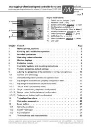
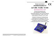
28 Additional sockets on the right side<br />
5<br />
28.1: mini-USB (standard)<br />
28.2: Flashing light output (nextConn<strong>II</strong> module only)<br />
28.3: External fan output (nextConn<strong>II</strong> module only)<br />
28.4: Temperature sensor input (nextConn<strong>II</strong> module only)<br />
28.5: AMS (Akku-Memory-Schnittstelle) for battery 2.<br />
On the opposite side of the charger also for battery 1.<br />
(Included as a standard. See also chapter 18.2)<br />
29 Specifications<br />
Common:<br />
All data given is based on a car battery voltage of 12.5 volts<br />
Recommended car battery 12V / bigger than 90 Ah, minimum 12 V / 63 Ah<br />
Tolerances @ battery 1 and 2 currents: typical 5%; max. about 15% resp. 250mA<br />
(larger value counts)<br />
next <strong>2x7</strong>-<strong>280</strong> next <strong>14</strong>-<strong>280</strong> next <strong>14</strong>-<strong>350</strong><br />
Weight ca. 730 g 733 g 770 g<br />
Dimensions (w*d*h) about 160 * 180 * 67 mm 160 * 180 * 67 mm 160 * 180 * 67 mm<br />
Supply voltage 10,0 - 25,0 V 10,0 - 25,0 V 10,0 - 25,0 V<br />
Under-voltage warning adjustable ~ 11,6 - 10,4 V 11,6 - 10,4 V 11,6 - 10,4 V<br />
- cut-off: volts lower ~ 0,5 V 0,5 V 0,5 V<br />
Supply current @13,8/12,0 V up to ~ 25/28 A 25/28 A 31/36 A<br />
Max. input power up to about 360 W 360 W 470 W<br />
Idle current about 100 mA 100 mA 100 mA<br />
+ display illumination (disconnectable) ~ 50 mA 50 mA 50 mA<br />
Fan (internal) 12V/1,1 W/32 dBa 12V/1,1 W/32 dBa 2x 12V/1,1W/32 dBa<br />
Trickle currents Ni-Cd Trickle-Pulse Trickle-Pulse Trickle-Pulse<br />
Trickle currents other battery types none none none<br />
Additional connection terminals<br />
Standard mini-USB B mini-USB B mini-USB B<br />
Numb. of cell voltage measuring inputs** 2 x 7 2 x 7 2 x 7<br />
AMS connectors for battery 1 and battery 2 Yes Yes Yes<br />
Optional available for nextGen.<strong>II</strong>-„eco“ Geräte. Standard at nont-“eco“ devices<br />
1) Temperature sensor Sensor included ready for use<br />
Resolution: 1 °C<br />
2) Flashing light connector + cable cable about 2 m, flashing light not included<br />
Voltage: Supply voltage of the charger, max. current 2,0*** A<br />
3) Fan connector + cable cable about 2 m, fan not included<br />
Voltage: Supply voltage of the charger, max. current 2,0*** A<br />
Remarks<br />
* Charging is possible from 1 cell and higher. However the „Delta-Peak“ cut-off automatic has to do<br />
a hard job at low cell counts because the peak voltage of 1...3 cells is not very high.<br />
** via balancing connectors<br />
*** Flashing light current plus fan current added together = 3 amps max. current.<br />
**** When both batteries are discharging at the same time the the lower value is valid at the<br />
next-XX-<strong>280</strong> chargers.<br />
<strong>nextGeneration</strong> <strong>II</strong> Firmware version V 1.00 and higher<br />
2 General remarks and precautions<br />
Operating<br />
instructions<br />
Issue 03.10, page<br />
• The CE marking which you will find on all schulze products indicated that the equipment has been tested to<br />
meet the stringent European safety and radiation requirements; this does not mean that you do not have to<br />
follow these instructions!<br />
• Please remember that fast-charging batteries can push the batteries to their limit; never operate the chargers<br />
unattended. The charger as well as the batteries may get warm; when in use, they should be placed on an<br />
appropriately sized, non-heat-conducting and non-combustible surface. By following these rules extensive<br />
damage will be avoided in case of a mishap. This applies in the same way also for the attached batteries.<br />
• Many modern transmitters are equipped with an internal reverse-voltage protection diode. No “smart” charger can<br />
fast-charge these transmitters unless this diode is bypassed (shunted) (see chapter 11 for additional information<br />
when charging transmitters). Preferably, you can remove the transmitter’s battery and fast-charge it outside the<br />
transmitter. If you want to bypass the diode, contact the transmitter manufacturer. In many cases the fastcharge<br />
current for a transmitter pack should not exceed 1.2 Amp (see operating instructions of transmitter).<br />
In order to keep possible damages small in the case of an error, we recommend strongly to remove the<br />
batteries from the transmitter!<br />
• Do not modify the charger’s car battery power cables or the enclosed connecting clamps; they are very low loss<br />
to support the charger’s high-end charge capabilities. Do NOT insert fuses and NOT plug the charger into the<br />
car´s cigarette lighter!<br />
• RISK OF SHORT CIRCUIT! When a balancing cable is plugged into one of the balancing connectors of the<br />
charger the corresponding pins of the remaining two connectors are also carrying voltage. Therefore it is<br />
neither allowed to short pins nor connect a second pack to them!<br />
• Do not cross-connect individual output charge cables. Do not short circuit output 1 to output 2. Each<br />
charger outlet has its own sensing circuitry - but no cross-sensing. Prevent electrical contact between any<br />
charger outlet and your car’s body. All this may damage your charger and/or your batteries! It is safest to place<br />
the charger on the ground. Place the charger on a safe support, do not “hang” it somewhere under the hood.<br />
The best approach is to use a separate, fully charged, dedicated 12-V battery and take it to the flight line.<br />
• The internal software is always checking for operational errors. Do not operate the charger in the case that any of<br />
the cables are damaged or frayed, or in case the display panel indicates an ERROR.<br />
• The <strong>nextGeneration</strong><strong>II</strong> charging devices operates on a wide range of input votage but may also be connected<br />
directly to a 12 V car battery! DO NOT RUN YOUR ENGINE OR ATTEMPT TO CHARGE YOUR CAR<br />
BATTERY WITH EXTERNAL EQUIPMENT WHILE OPERATING THE CHARGER, OR AS LONG AS THE<br />
CHARGER IS HOOKED UP TO YOUR CAR’S BATTERY.<br />
• Should you decide to operate the charger from a (110V/240V AC to 12V or 13.8V DC) power supply, make sure<br />
this power supply is well regulated, can supply continuous DC current as high as 16 or 25 Amps**, has a very<br />
high output capacitance (>5000µF/16V), very low ripple and is insensitive to the frequency of the charger´s<br />
internal switching voltage converter. Using any other source is likely to damage your charger or your batteries,<br />
and voids the warranty. ALWAYS use a schulze nt-16A ... nt-40A power supply**, NEVER use an automotive<br />
battery charger as the source for the precision-engineered schulze charger.<br />
When a <strong>nextGeneration</strong><strong>II</strong> is connected to a dc-generator and/or more than one <strong>nextGeneration</strong><strong>II</strong> is powered by a<br />
single mains power supply, the power supply must be buffered (stabilized) by a buffer battery to avoid interaction<br />
between the charger(s) and the power supply.<br />
• Because of the high charge current capabilities of these chargers, you should always use high-quality, gold-plated<br />
connectors in the charge cables to your batteries. Also, use heavy-duty (12-g) flex wire. We recommend<br />
you to use either schulze short circuit protected charging cables and/or (in the USA) 4 mm bullet<br />
connectors, the Deans Ultra plug or similar. See you local hobby dealer.<br />
• Always connect the banana plugs of your charge cables first; then, connect the charge cable to the battery. Note<br />
that “open” banana plugs, when the charge cable and battery are connected, carry the full battery voltage (and<br />
current).<br />
• Avoid short circuits of the charge outputs or the batteries with the car body - the <strong>nextGeneration</strong><strong>II</strong> is not protected<br />
against wrong connections like the above mentioned. Place the charger best on the ground.<br />
• Note that all chargers have ventilation holes. Especially in discharge mode or when charging batteries less than<br />
12V, the charger will dissipate energy, and gets warm (the <strong>nextGeneration</strong><strong>II</strong> even has an internal cooling fan).<br />
Do not block these ventilation holes and make sure you allow free air flow.<br />
3
4<br />
Page Issue 03.10<br />
Operating<br />
instructions<br />
Issue 03.10, page<br />
<strong>nextGeneration</strong> <strong>II</strong> Firmware version V 1.00 and higher<br />
<strong>nextGeneration</strong> <strong>II</strong> Firmware V 1.00 and higher 45<br />
• Protect the charger from direct exposure to the sun (the sun´s heat may temporarily turn the LCdisplay<br />
black), dust, moisture and rain(!).<br />
Even though the schulze chargers are smart (they are micro-processor equipped and can determine a<br />
battery’s number of cells and its optimum charge current pattern), attempting to charge the following<br />
packs should not be attempted:<br />
• batteries built up from cells of different types and capacities<br />
• batteries made from different types of single cells<br />
• batteries with a different charging level of the cells<br />
• non rechargeable cells (dry cells)<br />
• batteries which are not expressly designed for fast charging and recharging.<br />
• defective or damaged packs or cells<br />
• already fully charged and/or hot batteries<br />
• battery packs with internal charge-current limiting devices (not valid for <strong>Schulze</strong> LiPoTx und LiPoRx)<br />
• batteries which are buildt-in (internal) to other equipment<br />
Do not exceed a battery’s design (maximum) charge current as specified by its manufacturer; note that the<br />
schulze chargers will still optimally charge these packs in automatic charging mode; you can program<br />
the charger’s max (limit) charge current.<br />
• Please bear in mind that new rechargeable batteries do not achieve their full capacity until they have<br />
completed several charge / discharge cycles. New batteries generally, and deep-discharged Nickel<br />
batteries in particular, may cause premature charge termination. For this reason it is absolutely essential<br />
to check that the automatic charge cut-off circuit works correctly and reliably; this is achieved by carrying<br />
out several test-charges, and checking the quantity of capacity charged into the pack.<br />
When charging battery packs with less than 4 nickel cells, exercise extra care to make sure that these are<br />
not over-charged (especially when you use less than the specified current for this battery type - see<br />
chapter 4). Packs which are (too) deeply discharged may cause the charger to cut off too soon.<br />
New batteries will only achieve their maximum capacity after several charge/discharge cycles; schulze<br />
chargers can be programmed to provide these cycles automatically.<br />
Please remember that battery packs can heat up considerably especially during multiple charge/discharge<br />
cycles; program your charger’s max discharge current to prevent overheating of the packs unless you<br />
provide additional cooling (some of the racing pilots use a tube with electric fan cooling!). Note that packs<br />
with low capacity will dangerously overheat at high discharge currents; the schulze charger can (and)<br />
should in this case be programmed to the limit discharge rate to a more acceptable level, for instance 1C<br />
and/or a battery cooler in combination with the temperature sensor for cut-off must be used. You can also<br />
use our build in low-temperature-start circuit. (Do not forget to activate temperature sensor to the right<br />
pack output and fix it at the right battery.)<br />
• Safety hint: Always verify the charge amount which your battery has absorbed (mAh or Ah) after a full<br />
charge (this is indicated on the display panel); this is probably the best gauge of a battery’s health and/or<br />
the proper operation of the charger. This way, you will avoid unexpected loss of power and/or control.<br />
An additional important function is the selection of the automatic cut-off circuit. Read the important comments<br />
in Chapter 12). Maximum protection against malfunctions of the cut-off automatic is provided by<br />
selecting additional cut-off criterias like max. temperature, max. energy input and max. charge time.<br />
For trouble-free operation, please check …<br />
… that the ferrite ring in the charge lead does not fracture. The ring prevents the charge lead acting as an<br />
aerial, i.e. radiating the pulsed frequency of the voltage converter and the processor in an unacceptable<br />
way. It is absolutely essential if the charger is to operate in the manner required for CE approval.<br />
… that the charge leads used for the Battery 1 and 2 outputs are as short as possible. The maximum total<br />
cable length - from the sockets to the battery - should be no longer than 70 cm. Twist the wires together<br />
to help suppress interference.<br />
… that the charge lead for charge output 1 is wound through one of the ferrite CE rings at least four times.<br />
These rings are probably familiar to you from long servo extension leads, albeit in a different size.<br />
The ring must be located no more than 5 cm from the banana plugs which are attached to the chargers end<br />
of the charge lead.<br />
27.5 Standard Balancing Adapters<br />
We offer a selection of printed circuit adapter boards which allow the balancing of 2s-7s (...<strong>14</strong>s)<br />
battery packs which are equipped with the most different balancing connectors. The balancing<br />
adapter boards are fitted with a cable containing an 8 pin EH socket - suited for the EH connector<br />
of the nextGen.<strong>II</strong>.<br />
27.5.1 BalAd-Set7 for battery 1 and/or battery 2<br />
Set containing 4 adapter PCBs with different plug systems (EH, XH, PQ, TP)<br />
and each with different pin counts to connect 2s ... 7s battery packs.<br />
27.5.2 BalAd-EH7 for battery 1 and/or battery 2<br />
Adapter PCB equipped with 6 EH male connectors of different pin counts<br />
to connect 2s ... 7s battery packs<br />
27.5.3 BalAd-XH7 for battery 1 and/or battery 2<br />
Adapter PCB equipped with 6 XH male connectors of different pin counts<br />
to connect 2s ... 7s battery packs<br />
27.5.4 BalAd-PQ7 for battery 1 and/or battery 2<br />
Adapter PCB equipped with 6 PQ male connectors of different pin counts<br />
to connect 2s ... 7s battery packs<br />
27.5.5 BalAd-TP7 for battery 1 and/or battery 2<br />
Adapter PCB equipped with 4 TP male connectors of different pin counts<br />
to connect 2s ... 7s battery packs<br />
27.5.6 BalAd-EH<strong>14</strong>. For battery 1 use only - due to the fact that all <strong>14</strong> balancing circuits<br />
can be used and the second balancing group is no longer available for battery 2.<br />
• Adapter PCB equipped with 13 EH male connectors of different pin counts<br />
to connect 2s ... 24s battery packs which can be separated into 2 packs.<br />
Note: When the packs are combined or equipped with two connectors then it is essential<br />
that the pack with the lower cell count (2...7) has to be connected to the balancing output<br />
EH1 of the charger - and also with the black ("-") power cable to the charge output 1.<br />
27.6 <strong>Schulze</strong> Balancinbg Cables<br />
The sets are assorted to make 10- and 20-pin. balancing cables<br />
which can be coded battery typical - to allow „plug-and-play“<br />
charging of your batteries with modern <strong>Schulze</strong> chargers.<br />
Note: A detailled description of the pinout and the mounting<br />
instructions are enclosed in the balancer cable kits<br />
(BalCab10 or 20 - Set).<br />
BalCab10-Set/BalCab20-Set BalCab10/20-Verlängerung<br />
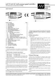
The principle of connection<br />
of <strong>Schulze</strong> Balancers<br />
(cell arrangement as the storeys in<br />
a high-rise building)<br />
+ cell 7 (seventh storey)= + battery<br />
+ cell 6 (sixth storey) = - cell 7<br />
+ cell 5 (fifth storey) = - cell 6<br />
+ cell 4 (fourth storey) = - cell 5<br />
+ cell 3 (third storey) = - cell 4<br />
+ cell 2 (second storey)= - cell 3<br />
+ cell 1 (first storey) = - cell 2<br />
- cell 1 (ground floor) = earth = - battery
44<br />
Page Issue 03.10<br />
Operating<br />
instructions<br />
Issue 03.10, page<br />
<strong>nextGeneration</strong> <strong>II</strong> Firmware version V 1.00 and higher<br />
<strong>nextGeneration</strong> <strong>II</strong> Firmware V 1.00 and higher 5<br />
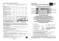
27 Balancing and measuring connectors<br />
27.1 The charger contains two balancer connectors which could be used directly (without any<br />
adapter). Each balancing connector is equipped with a 8-pin EH-connector (male, white), on<br />
which on principle can be connected battery packs up to 7s - when they are plugged in left<br />
justified(!). This means that two 2s-7s batteries can be charged and balanced independently<br />
from each other at the same time.<br />
• Practically you should use separate balancing adapters for each cell types with a collection of<br />
connectors for each cell count (see below).<br />
• When you connect a battery pack with two balancing connectors or 8 cells or more then both<br />
balancing groups are working automatically for output 1. In this way up to <strong>14</strong> LiPo cells in only<br />
one pack can be balanced. The charge output 2 can further be used regardless of charge<br />
output 1 if it was not coupled to charge output 1. Only the second balancing group is in this case<br />
no longer available for output 2.<br />
27.2 Between both EH plugs a 24-pin socket is located for the <strong>Schulze</strong> adapter boards BalAd-SE4-<br />
7-<strong>14</strong> or BalAd-SE4x7.<br />
• These boards are assembled with <strong>Schulze</strong> BalCab male connectors and in addition to it<br />
equipped with two EH connectors for the simple reason that the board covers the two connectors<br />
on the charger's main board below. Please place the adapter board completely and horizontally<br />
so that the board rests fully upon the chargers plastic case.<br />
Note: • Do never plug the balancing connectors of different battery packs to those connectors which<br />
are electrically joined in parallel. These thereby are causing short circuits and it can<br />
happen that the connected battery pack will be damaged. Also the copper leads on the<br />
PCB could explode.<br />
• Danger of short circuits! Open pins of the electrically joined connectors lead voltage<br />
when to one of the connectors a balancing cable is connected!<br />
27.3 <strong>Schulze</strong> BalAd-SE4-7-<strong>14</strong><br />
To avoid short circuits it is essential that you use only one of<br />
the different balancing connectors which are assigned to<br />
the same battery because they are connected to each<br />
other by printed wires!<br />
27.3.1 Battery 1; up to max. 7s: Please use either the left BalCab10 connector (10-pin, black) or<br />
the left 8-pin EH connector (white).<br />
27.3.2 Battery 1; up to max. 7s: Please use either the right BalCab10 connector (10-pin, black) or<br />
the right 8-pin EH connector (white).<br />
27.3.3 Battery 1+2; up to <strong>14</strong>s: When you use the BalCab20 connector in the middle the it is not<br />
allowed to use any of the other 4 connectors on the left (27.3.1) and the right (27.3.2).<br />
27.4 <strong>Schulze</strong> BalAd-SE4x7<br />
To avoid short circuits you may use only one of the different<br />
balancing connectors which are assigned to the same<br />
battery because they are connected to each other by<br />
printed wires!<br />
27.4.4 Battery 1; up to 7s: It is essential that you use either the left BalCab20 socket (20-pin,<br />
black) or the left 8-pin EH connector (white).<br />
27.4.5 Battery 2; up to 7s: It is important that you use either the right BalCab20 connector (20-pin,<br />
black) or the right 8-pin EH connector (white).<br />
3 Commonly used Terms<br />
Final charge voltage: the voltage at which the battery's charge limit (capacity limit) is reached. The<br />
charge process switches from a high current to a low maintenance rate (trickle charge) at this<br />
point. From this point on further high current charging would cause overheating and eventual<br />
terminal damage to the pack.<br />
Final discharge voltage: the voltage at which the battery's discharge limit is reached. The<br />
chemical composition of the batteries determines the level of this voltage. Below this voltage the<br />
battery enters the deep discharge zone. Individual cells within the pack may become reversepolarised<br />
in this condition, and this can cause permanent damage.<br />
Memory effect: The real memory effect has been recorded by Nasa, caused by repeated charge /<br />
discharge cycles. Nasa has found that full capacity can be regained by overcharging the cells. In<br />
modelling applications different effects are responsible for the reduction in cell capacity. The<br />
problem can be cured by balancing the cells (see below), and prevented by the measures<br />
described in Chapter 4.1.3.<br />
Battery conditioning: a method of regaining full (nominal) capacity by alternately charging and<br />
discharging the pack, sometimes several times. This process is especially useful after a long<br />
period of non-usage (e.g. after purchase, or after several weeks without flying), and is also used<br />
to disperse the memory effect (see below). The effect of battery conditioning is to break down the<br />
coarse crystaline structure (low capacity) inside the cell and convert it into a fine crystaline one<br />
(high capacity).<br />
Power-On (- reset): the status of the <strong>nextGeneration</strong><strong>II</strong> after it has been connected to the car<br />
battery.<br />
Ready message: charger ready to run the program you just have selected (batteries not connected).<br />
The display shows "ready".<br />
C: Coulomb or capacity: Unit of measurement relating to the quantity of charged energy. In<br />
conjunction with charge current data this unit is used to determine the recommended / prescribed<br />
charge current of a battery of a given capacity. Example: if the charge or discharge current of a<br />
500 mAh battery is 50 mA, we refer to this as a charge or discharge at one tenth C (C/10 or<br />
1/10 C).<br />
A, mA: unit of measurement relating to charge or dis-charge current. 1000 mA = 1 A (A=Ampere,<br />
mA=Milliampere)<br />
Ah, mAh: unit of measurement for the capacity of a battery (Amperes x time unit; h = hour). If a<br />
pack is charged for one hour at a current of 2 A, it has been fed 2 Ah of energy. It receives the<br />
same quantity of charge (2 Ah) if it is charged for 4 hours at 0.5 A, or 15 minutes (=1/4 h) at 8 A.
6<br />
Page Issue 03.10<br />
Operating<br />
instructions<br />
Issue 03.10, page<br />
<strong>nextGeneration</strong> <strong>II</strong> Firmware version V 1.00 and higher<br />
<strong>nextGeneration</strong> <strong>II</strong> Firmware V 1.00 and higher 43<br />
4 Useful information about batteries and maintenance<br />
4.1.1 General information<br />
Do not charge below 0°C, optimum is 10...30°C.<br />
A cold cell is not capable of accepting as much current as a warm one. For this reason you must<br />
expect differences in charge characteristics if you use fully automatic charge current calculation for<br />
your nickel cells (in Winter the charging properties will be worse than in Summer). The best<br />
working temperature for a Ni-MH cell is 40 ... 60°C. At lower temperatures the cell can not supply<br />
higher currents. Caution when using those cells at a receiver battery in a helicopter in the wintertime.<br />
The lower the internal resistance of the battery, the higher the charger can increase the charge<br />
current for that battery. For a battery charger which sets the current automatically the<br />
resistance of the cable is added to the internal resistance. For this reason: use heavy duty<br />
wire (large cross-section), even for receiver batteries, and keep them short. Do not charge<br />
via a switch or switch harness!<br />
If you wish to measure the maximum battery capacity a suitable discharge current is usually 1/10 C.<br />
4.1.2 Reflex charging<br />
Charging processes which include a brief discharge pulse definitely have the effect that the battery<br />
is several degrees cooler at the end of the process. However, from the point of view of the<br />
competition operator this is an undesirable effect, as the cell chemistry can only supply high<br />
currents if its temperature is raised to a certain extent.<br />
All these effects, whether they actually occur or are simply hear-say, have no practical<br />
significance if batteries are correctly handled in the first place. When a battery is full, you<br />
can’t fill it any fuller! Read also chapter 4.1.3 for this subject area.<br />
4.1.3 Memory effect of Ni-Cd & Ni-MH cells<br />
If cells are repeatedly stored partially discharged, or are recharged from a half-discharged state,<br />
what is known as the memory effect sets in. The cells note that their full capacity is not required,<br />
and react by refusing to make it available.<br />
One aspect of this is that the crystalline chemical structure inside the cell changes; the cell‘s<br />
resistance rises and its voltage collapses under load, with the result that “full capacity” can no<br />
longer be exploited at normal discharge currents.<br />
Even if reflex charging were to eliminate the memory effect, there is no denying the necessity to<br />
store your cells in the discharged state; this applies to Ni-Cd cells and also to Ni-MH cells.<br />
A characteristic fact of these cells is that they self-discharge - and the rate of self-discharge is<br />
different for each individual cell in a battery pack! If a fully charged pack is left for a considerable<br />
time, it will eventually consist of cells of widely varying states of charge.<br />
If at this point you ...<br />
a) ... give the pack a full charge: the cell with the highest charge will be overcharged, heat up and<br />
be ruined, while the cell with the least charge will still not be full after the same period of charging.<br />
b) ... discharge the pack: the cell with the least charge will be completely flat first, then reverse<br />
polarity and often suffer an internal short-circuit. At the point when this happens, the cell with the<br />
most charge is still not yet completely discharged.<br />
This is a reliable method of wrecking your most valuable packs - and rest assured that reflex<br />
charging will make absolutely no difference. However, there is one method of avoiding the<br />
problem: discharge cells after use, and recharge them just before use!<br />
26 Data format PC interface<br />
Data transfer rate: 9600 Baud, No Parity, 1 Stop-Bit, 1 Start-Bit<br />
Data block - format without single cell voltage output (without balancer):<br />
P:sssss:uuuuu:iiiiiVSttt (ASC<strong>II</strong>)<br />
Data block - format with single cell voltage output (balancer cable is connected):<br />
P:sssss:uuuuu:iiiiiVSttt;uuuZ1;uuuZ2;uuuZ3;uuuZ4;uuuZ5;uuuZ6;uuuZ7;uuuZ8;<br />
Legend: P Pack-Output-No.<br />
: Separation sign<br />
sssss Time in seconds<br />
: Separation sign<br />
uuuuu Battery voltage in millivolt<br />
: Separation sign<br />
iiiii Current in milliampere<br />
V[:,-] Charge/discharge indicator<br />
S[l,L,E,P,v...] Charge-/Discharge program status<br />
ttt[-, ,0..9] Temperature (***)<br />
; Separation sign<br />
uuuZ1 Voltage of cell 1 in millivolt<br />
; Separation sign<br />
uuuZ2 Voltage of cell 2 in millivolt<br />
;<br />
...<br />
Separation sign<br />
; Separation sign<br />
uuuZ6 (or uuuZ13) Voltage of cell 6/13* in millivolt<br />
; Separation sign<br />
uuuZ7 (or uuuZ<strong>14</strong>) Voltage of cell 7/<strong>14</strong>* in millivolt<br />
Hints:<br />
; Separation sign<br />
(*) Not existing cells are displayed as „ 0“.<br />
No leading zeros are displayed.<br />
Commentary lines starts (as a rule) with a leading „* “<br />
Example: * PackOutputNo UsedProgram CellCount BatteryType<br />
Re cell count:<br />
Calculated cell count at nickel-batteries or<br />
Selected cell count at lead- and lithium-batteries.<br />
(***) The display of the temperature:<br />
When a temperature sensor is connected (nextConn-Set-<strong>II</strong> necessary) the temperature of the<br />
connected temperature sensor is displayed in the format shown above - and is also shown in the<br />
LC-display of the nextGen.<br />
Otherwise one of the internal temperatures is displayed:<br />
a) At discharge programs = measured near the cooling fins<br />
b) At charge programs = measured near the voltage converter or - at the next-<strong>14</strong>-<strong>350</strong> only: near the<br />
balancing stages, when these are hotter than the voltage converter (when they are balancing<br />
extremly de-balanced batteries).<br />
The format changed into: tti, i.e. two temperature digits followed by an „i“ (means: „internal temperature“).
42<br />
Page Issue 03.10<br />
Operating<br />
instructions<br />
Issue 03.10, page<br />
<strong>nextGeneration</strong> <strong>II</strong> Firmware version V 1.00 and higher<br />
<strong>nextGeneration</strong> <strong>II</strong> Firmware V 1.00 and higher 7<br />
24 Standard ready-made configurations<br />
For your own configurations space for 40 or 60 setups are available - which can be assigned alternatively<br />
from the battery outputs 1 or 2. If you are in the menu for battery 1 you are not able to read setups written<br />
by the battery 2 menu (or the other way round - the name of the configuration is crossed out).<br />
We recommend that you store setups for the battery 2 output from "behind" i.e. beginning with the<br />
last (highest) setup number.<br />
If you have your own ideas about configuration names, or if you wish to alter the order of the configurations,<br />
you can certainly do this exactly as you wish within the limits of the software's facilities. For<br />
example, to copy a particular configuration to a different number, simply read in the configuration<br />
with the old number, then store it under the new number. Only the name has to be altered.<br />
# Outp. Name B.Type Program cCurr [mA] dCurr Quant. Time CutOff<br />
1 1 Po-C3Ah7 Li-Po fix_C 3700 (3700) 4000 90 v-max<br />
2 1 Po-C5Ah0 Li-Po fix_C 5000 (5000) 5500 90 v-max<br />
3 1 Po-CD3A2 Li-Po fix_C 3200 (3200) 3600 90 v-max<br />
4 1 MH-C3Ah6 Ni-MH autoC max. (max.) 5000 120 sensitive<br />
5 1 MH-D3Ah6 Ni-MH autoD (max.) max. (5000) (120) (sensit.)<br />
6 1 MH-CD3A6 Ni-MH autoCD max. max. 5000 120 sensitive<br />
7 1 Cd-C2Ah4 Ni-Cd autoC max. (max.) <strong>280</strong>0 60 normal<br />
8 1 Cd-D2Ah4 Ni-Cd autoD (max.) max. (<strong>280</strong>0) (60) (normal)<br />
9 1 Fe-C1Ah2 Li-Po festL 1200 - 1600 90 v-max<br />
10 1 Pb-C7Ah0 Lead festL 2500 (2500) 7000 300 v-max<br />
Hint: Values in parenthesis are set but not used.<br />
For the battery 2 output all pre-settings are copied in reverse order to the memory:<br />
Using the next-<strong>14</strong>-<strong>350</strong> all values of setting No. 60 (battery 2) are copied from setting No. 1 (battery 1), all<br />
values of setting No. 59 (battery 2) are copied from setting No. 2 (battery 1), e.t.c.<br />
With the next-...-<strong>280</strong> the storage location No. 40 (battery 2) corresponds to the storage location No. 1<br />
(battery 1), the storage location No. 39 (battery 2) corresponds to the storage location No. 2 (battery 1), ...<br />
Addition: All CombinationCycles, C-Rates, CellCounts (except nickel batteries) = 1;<br />
25 Standard setup charge-/discharge programs<br />
Menu output 1 output 2<br />
Battery type ("bType") LiPo LiPo<br />
Charge/discharge program ("prog.") fix_C fix_C<br />
Charge current ("cCurr") 3.00 A 3.00 A<br />
Discharge current ("dCurr") 3.00 A 3.00 A<br />
Cut-off mode ("cutOf") normal normal<br />
Cut-off delay ("delay") 1 minute 1 minute<br />
Cell count ("cells") - can not be configured 2 2<br />
Charge quantity limit ("quan>") 4000 mAh 4000 mAh<br />
Charge time limit ("time>") 60 minutes 60 minutes<br />
Temperature cut off limit ("temp>") OFF OFF<br />
Discharge protection Diode ("diode") NO NO<br />
Refresh (short discharge pulses) ("refr.") OFF OFF<br />
Charger parameters:<br />
Car battery minimum voltage 11.2 V<br />
Temperature 60 °C<br />
Current / power (depends on type of charger) maximum<br />
Full / Empty Light Output Flashing light<br />
Other parameters: All CombinationCycles, C-Rates, CellCounts (except nickel batteries) = 1; lithium-full/<br />
empty-limits as stated in chapter 4 or shown in Fig. 7.5.2.<br />
4.2 Nickel-Cadmium-batteries (Ni-Cd)<br />
Nominal voltage level: 1.2 V / cells.<br />
Selecting the fast charge current (manual setting):<br />
Charge current = 2 C (never less!) (C=nominal battery capacity). Otherwise the cells do not make a<br />
detectable peak and the peak cut off automatic is not able to work resp. to work reliable.<br />
Maximum continous discharge current:<br />
Currents of 10 C to 30 C are possible, depending on cell type.<br />
Long time storage:<br />
Empty i.e. discharged to the discharge voltage cut off level, at low temperature (-20°C to +10°C).<br />
Maintenance: Charging: The automatic current setting circuitry (patent applied for) provides optimum<br />
protection to your Ni-Cd batteries during charging. The reduced current towards the end of the charge<br />
ensures a completely full pack combined with only a slight temperature rise, as you will easily see in<br />
comparison with conventional constant current techniques.<br />
Do not use the automatic charge current calculation of the Ni-Cd batteries when charging Ni-MH batteries!<br />
Discharging: To prevent your cells from memory effect and to keep the full capacity you have to discharge it<br />
after use, even when you store it over night (select Auto-D program to discharge down to 0.85V / cell).<br />
If a battery is brand-new or used irregularly it is often only possible to condition it completely by carrying<br />
out several discharge - charge cycles. Amongst model car operators it is standard practice to erase<br />
any memory effect by completely discharging each cell individually via a resistor (approx. 68 Ohm).<br />
This deliberately ”un-forms” the pack, but it can cause the automatic charge termination circuitry to<br />
switch off the current prematurely during the charge process. Remedy: Discharge with a 10 Ohm<br />
resistor in series to a 1 A diode (1N4001).<br />
For receiver batteries special types such as the Sanyo KR500AAEC / N500AC (high reliable) are a good choice.<br />
Warning: If using reduced charge current with 1-6 cells makes the voltage peak in the charge curve very<br />
slight, especially with batteries of high nominal capacity. In this situation the charger is sometimes<br />
unable to detect the ”full” condition due to the ill-defined peak.<br />
4.3 Nickel-Metal-Hydride batteries (Ni-MH)<br />
Voltage level: 1.2 V / cell.<br />
Selecting the fast charge current manually (not automatically):<br />
Charge current typical 1 C (never less!) (set a fixed current of, for example, 1.2 A with 1100 mAh<br />
batteries, or 3 A with 3 Ah cells). Otherwise the cells do not make a detectable peak and the peak cut<br />
off automatic can not work reliable. Some modern high-current Ni-MH cells made by particular<br />
manufacturers can safely be charged at a higher rate of up to 1.6 C (Panasonic 3000: 3,5 - 4A, GP<br />
3000/3300: 3 A, Saft 3000: 3 A (not if battery is charged inside a transmitter!), Sanyo 3000/3300: 4 - 5A).<br />
Because of its high internal resistance do not charge high capacity cells of mignon(AA)-size from 1500<br />
mAh upward with automatic current calculation (AutoC, -CD, -DC).<br />
Maximum continous discharge current:<br />
Currents of 5 C to 15 C are possible, depending on cell type.<br />
Long time storage:<br />
Store old generation cells empty, (those types which had been available in the SUB-C size up to<br />
3.3 Ah) i.e. discharged to the cut off level (see maintenance), at low temperature (-20°C to +10°C).<br />
The new generation cells should NOT be stored empty - The self discharge rate is too high!<br />
Discharge down to the cut off level (see maintenance) and then charge in about 30% of their<br />
capacity (use the quantity cut off feature). Store all cells at low temperature (-20°C to +10°C).<br />
Maintenance: To protect your Ni-MH batteries from the memory effect and keep the full capacity, discharge the<br />
cells after use down to the discharge voltage limit even when you store it over night and add 30% (new cell<br />
types). Never discharge by car bulbs or the drive motor (premature charge termination!), but use only the<br />
Auto-D programm when the battery type Ni-MH is selected. The cut off voltage is 1 volt / cell. This eliminates<br />
the danger of deep discharge termination and polarity reversal (over-discharge).<br />
It is important that you take the trouble to give Ni-MH cells when storing at +10...30°C a charge /<br />
discharge cycle around every four weeks, otherwise they become tired, and have to be pampered.
8<br />
Page Issue 03.10<br />
Operating<br />
instructions<br />
Issue 03.10, page<br />
<strong>nextGeneration</strong> <strong>II</strong> Firmware version V 1.00 and higher<br />
<strong>nextGeneration</strong> <strong>II</strong> Firmware V 1.00 and higher 41<br />
to restore them to full vigour. This involves going through the tiresome business of many repeated<br />
charge / discharge cycles.<br />
The automatic current setting circuitry (patented) provides optimum protection to your Ni-MH batteries<br />
during charging. Please use the Ni-MH automatic current calculation always with a correctly<br />
adjusted charge quantity monitoring circuit (see chapter <strong>14</strong>.2.6). Do not use the Ni-Cd automatic<br />
current selection for Ni-MH batteries!<br />
Warning: Never charge fully charged Ni-MH batteries with the Auto C (or ..CD programs): Overheating<br />
and danger of explosion! The cut off automatic is disabled for about the first 7 minutes<br />
of charging - this could lead to a minimum charge time of about 10 minutes!<br />
Warning: At lower cell counts (1-6) and low charge currents (below 1 C) the battery makes only a very<br />
low voltage peak when fully charged. Under those conditions the cut off automatic works less reliable<br />
then with higher currents and/or higher number of cells.<br />
Hint: The optimum operating temperature of Ni-MH batteries is 40-60°C!<br />
Typical for Sanyo Twicell industry types with flat top and RC3600HV cells:<br />
High maximum load capacity and voltage level.<br />
Typical for Panasonic P3000NIMH cells:<br />
High maximum charge capacity and voltage level, load current up to 40 amps.<br />
Typical for GP 3300 cells:<br />
Extremely high charge capacity, good voltage level.<br />
Can be discharged with medium currents (about 40...45 amps; from year 2003 up to 60 amps).<br />
Typical for GP 3700 / GP4300 / IB4200 cells:<br />
Very high voltage level. Very high self discharge current. Up to 60 amps load current.<br />
4.4 Lead-acid batteries (Pb) ...<br />
... and VRLA (valve regulated lead-acid batteries = lead-gel batteries)<br />
Nominal voltage level: 2.0 V / cell.<br />
Charge voltage level: 2.3 V / cell; 2.42 V / cell for 3 hours max.<br />
Min. discharge voltage: 1.7 V / cell (this reduces lifetime).<br />
Number of cells to be selected on the <strong>nextGeneration</strong><strong>II</strong>:<br />
Nominal voltage of the battery to be charged divided by the nominal voltage level of lead-acid<br />
battery cells = cell count. Example: 12 V-Lead acid battery divided by 2,0 V => 6 cells.<br />
Selecting the fast charge current:<br />
Charge current = 0.15 C (C = nominal battery capacity) if no data sheets are available.<br />
Charge current up to 0.4 C for special types.<br />
Maximum continous discharge current:<br />
Typically 0.2 C, short time load up to 1 C.<br />
Long time storage:<br />
Full at low temperature, more precise:<br />
At +10°C up to 12 month, at +10...20° max. 9 month, at +20...30°C max 6 month, at +30...40°C 3 month.<br />
Charge again after this period.<br />
Maintenance: In contrast to Ni-Cd/Ni-MH batteries, lead-acid batteries must be fully recharged after<br />
use in order to maintain full capacity.<br />
The nominal capacity can be reduced very quickly by incorrect handling (overloading, repeated<br />
100% discharges, and especially by deep-discharges). Please observe the battery manufacturer’s<br />
recommendations.<br />
Typical: The characteristics of lead-acid batteries are quite different to those of the Ni-Cd sealed<br />
cell packs which are used as the power source in model aircraft, cars and hydro-boats. They can<br />
only tolerate relatively low currents relative to their capacity if their full capacity is to be exploited,<br />
and/or the voltage is not to collapse too far.<br />
Used as single-cell glowplug energiser batteries and power source in some scale boats.<br />
Low self-discharge rate.<br />
After having pressed the first of two device parameter sets<br />
is shown. Following parameters can be selected:<br />
Fig. 23.12 left<br />
23.12.2 le: external fan off/on (*)<br />
23.12.3 le: external "full"-light (off/flashing/on) (*)<br />
23.12.4 le: "full"- and/or key buzzer off/on.<br />
23.12.5 le: Display background illumination off/on.<br />
23.12.6 le: Charge quantity limit is also valid for discharging<br />
(Coupling off/on)<br />
23.12.7 le: Changing owners name (see fig. 23.15)<br />
Fig. 23.12 right<br />
23.12.2 ri: max. primary current (supply current)<br />
23.12.3 ri: max. charge power<br />
23.12.4 ri: under volt. warning limit car battery. Shows true warning<br />
voltage for 12V/18V/24V batteries. Menu is standardized on 12 V.<br />
23.12.5 ri: Cut-off temperature limit for the external temperature<br />
sensor (*). Hint: The sensor has to be activated by<br />
assigning it to a battery output.<br />
23.12.7 ri: Changing the pass word to enable the change of the<br />
owners name (see fig. 23.15).<br />
Another push on leads to<br />
Fig. 23.13 left<br />
23.13.2 le: Value selection via table (Fig. 23.11- tabular) or<br />
numerical (digit by digit 3 modes - Fig. 23.16):<br />
nuStrict: Values between 0-9 can be selected.<br />
nuAround: 0 follows 9 or the other way round.<br />
numCarry: neighbouring digits are also affected at a run<br />
over of a digit (9->0 or 9->0).<br />
Hint: When single digits are changed and the result is an<br />
under- or overflow of the limit of the complete value then the<br />
value is set to the max. or min. limit.<br />
Hint: Only long tables can be adjusted digit by digit.<br />
23.13.3 le: Charger starts working after connecting the battery<br />
or starts manually after pressing the key.<br />
23.13.4 le: The balancing circuit works at „automat.“ with<br />
sliding precision: the higher the cell voltage the closer the<br />
voltage deviation of the cells in the pack OR fixed values<br />
between 4 mV to 20 mV OR "OFF" (no balancing => only<br />
voltage measuring) are allowed.<br />
23.13.5/6/7 le: Fine tuning of the Li-discharge voltage limit (see<br />
also chapter 21.11.5).<br />
23.13.8 le: Charge circuit of battery 2 is paralleled to output 1.<br />
This leads to double power on output 1.<br />
Fig. 23.13 right<br />
23.13.2 ri: Menus narrow ("small", Fig. 23.13, all parameters at<br />
a glance or "wide" (Fig. 23.<strong>14</strong>). This menu changes automatically<br />
when reaching the first/last value or after pressing or<br />
.<br />
23.13.3 ri: Resetting the complete device and battery<br />
parameter sets to standard values (does not affect the values<br />
of the clients setups).<br />
23.13.4 ri: Resetting of the capacity display of the car battery<br />
which is shown on the info screen Fig. 23.6.<br />
23.13.5/6/7 ri: Fine tuning of the Li-charge voltage limit.<br />
23.13.8 re: All letters on the screen are changed into capitals.<br />
Fig. 23.15: Description see chapter 16.10.<br />
Fig. 23.16: +/- cursor can be moved by pressing and .<br />
Leading "zeros" show the possible digit count.<br />
(*) NextConn-Set-<strong>II</strong> necessary!<br />
Device parameter screen 1 Fig. 23.12<br />
ParameterSet ParameterSet 1 1 nextGen<br />
nextGen<br />
fan fan ® OFF OFF curr> curr> curr>®* curr> curr> * 28A<br />
28A<br />
light light®blink light blink powr> powr>® powr> 250W 250W<br />
250W<br />
buzzr buzzr® buzzr ON ON ON batt> batt>®11*2V<br />
batt> 11*2V<br />
illum illum® illum ON ON ON temp> temp>®*60°C<br />
temp> *60°C<br />
dQuan dQuan® dQuan OFF OFF melod melod®0, melod 0, 0, 0<br />
0<br />
name name name ®>new< >new< passw passw®>new<<br />
passw >new<<br />
<strong>Schulze</strong> <strong>Schulze</strong> <strong>Elektronik</strong> <strong>Elektronik</strong> <strong>GmbH</strong><br />
<strong>GmbH</strong><br />
Device parameter screen 2 Fig. 23.13<br />
ParameterSet ParameterSet 2 2 nextGen<br />
nextGen<br />
nextGen<br />
value value value®tabul value tabul menu menu menu®small<br />
menu small<br />
start start start®autom start autom autom setTo setTo®deflt<br />
setTo deflt<br />
balan balan balan®autom balan autom autom carBt carBt®reset<br />
carBt reset<br />
uLiPo uLiPo uLiPo®*3000 uLiPo *3000 *3000 ULiPo ULiPo®*4200<br />
ULiPo *4200<br />
uLiIo uLiIo uLiIo®*2700 uLiIo *2700 *2700 ULiIo ULiIo®*4100<br />
ULiIo *4100<br />
uLiFe uLiFe uLiFe®*2000 uLiFe *2000 *2000 ULiFe ULiFe®*3650<br />
ULiFe *3650<br />
b1+b2 b1+b2 b1+b2® b1+b2 OFF OFF UpCas® UpCas® OFF<br />
OFF<br />
Dev. parameter screen 2 wide Fig. 23.<strong>14</strong><br />
ParameterSet2 ParameterSet2 nextGen<br />
nextGen<br />
Value Value selecton selecton ® tabul<br />
tabul<br />
Start Start release release ® autom<br />
autom<br />
BalancPrecision<br />
BalancPrecision® BalancPrecision autom<br />
autom<br />
EMPTYvolt.LiPo EMPTYvolt.LiPo ® *3000<br />
*3000<br />
EMPTYvolt.LiIo EMPTYvolt.LiIo ® *2700<br />
*2700<br />
EMPTYvolt.LiFe EMPTYvolt.LiFe ® *2000<br />
*2000<br />
coupling coupling b1+b2 b1+b2 b1+b2 ® OFF<br />
OFF<br />
Name selection screen Fig. 23.15<br />
!"#äöü°()*+,-./01234<br />
!"#äöü°()*+,-./01234<br />
56789:;?@ABCDEFGHI<br />
56789:;?@ABCDEFGHI<br />
JKLMNOPQR<br />
JKLMNOPQRSTUVWXYZ[\]^<br />
JKLMNOPQR TUVWXYZ[\]^<br />
_`abcdefghijklmnopqrs<br />
_`abcdefghijklmnopqrs<br />
tuvwxyz{|}<br />
tuvwxyz{|}<br />
,=character ,=character set<br />
set<br />
name name select=<br />
select=<br />
<strong>Schulze</strong><strong>Elektronik</strong><strong>GmbH</strong><br />
chulze<strong>Elektronik</strong><strong>GmbH</strong><br />
Charge quantity selection b.2 Fig. 23.16<br />
Param. Param. Param. Selection Selection batt2<br />
batt2<br />
ChargeCapacity ChargeCapacity cutOff<br />
cutOff<br />
+--------+<br />
+--------+<br />
| | + + | | + + change<br />
change<br />
--> --> 2000mAh
1<br />
2<br />
3<br />
4<br />
5<br />
6<br />
7<br />
8<br />
1<br />
2<br />
3<br />
4<br />
5<br />
6<br />
7<br />
8<br />
40<br />
Page Issue 03.10<br />
Fig. 23.8 Parameter screen battery 1<br />
1 ParameterSet ParameterSet battery battery 1<br />
1<br />
2 bType bType® bType LiPo LiPo cells cells® cells +B +B 5<br />
5<br />
3 prog3 prog3®fixCD prog3 fixCD cRate cRate®* cRate * * 1.0<br />
1.0<br />
4 cCurr cCurr®3.50A cCurr 3.50A quan> quan> quan>® quan> quan> <strong>350</strong>0<br />
<strong>350</strong>0<br />
5 dCurr dCurr®4.00A dCurr 4.00A time> time>® time> 1h30<br />
1h30<br />
6 cutOf cutOf®v-max cutOf v-max temp> temp>® temp> OFF<br />
OFF<br />
7 delay delay® delay 2min 2min diode diode® diode OFF<br />
OFF<br />
8 stora stora® stora NO NO NO refr. refr.® refr. OFF<br />
1<br />
Fig. 23.9 Curve screen battery 2<br />
0NiMH 0NiMH 00:00 00:00 0.00V 0.00V b<br />
2 autoC autoC (2.00A) (2.00A) 0mAh 0mAh a<br />
3 8V 8V<br />
t<br />
4<br />
t<br />
5<br />
6<br />
ready<br />
ready<br />
2<br />
7<br />
1 1 2 2<br />
2<br />
8 2V 2V 2V t t<br />
t<br />
1<br />
2<br />
3<br />
4<br />
5<br />
6<br />
7<br />
8<br />
Fig. 23.7 Curve screen battery 1<br />
5LiPo 5LiPo 00:00 00:00 0.00V 0.00V b<br />
3fixCD 3fixCD (3.50A) (3.50A) 0mAh 0mAh a<br />
8V 8V<br />
t<br />
t<br />
ready<br />
ready<br />
11 11<br />
11<br />
1 1 1 2<br />
2<br />
2V 2V 1234 1234 5 5 t<br />
t<br />
Fig. 23.10 Parameter screen battery 2<br />
ParameterSet ParameterSet battery battery 2<br />
2<br />
bType bType® bType NiMH NiMH NiMH cells cells® cells 0<br />
0<br />
prog. prog.®autoC prog. autoC cRate cRate® cRate -<br />
-<br />
cCurr cCurr®2.00A cCurr 2.00A quan> quan>® quan> 2000<br />
2000<br />
dCurr dCurr®4.00A dCurr 4.00A time> time>® time> 1h30<br />
1h30<br />
cutOf cutOf®sens. cutOf sens. temp> temp> temp>® temp> OFF<br />
OFF<br />
delay delay® delay 7min 7min diode diode® diode NO<br />
NO<br />
stora stora® stora NO NO refr. refr.® refr. OFF<br />
Fig. 23.11 charge quantity selection b.2<br />
Param. Param. Selection Selection batt2<br />
batt2<br />
ChargeCapacity ChargeCapacity cutOff<br />
cutOff<br />
+--------+<br />
+--------+<br />
| | 2.2 2.2 Ah| Ah| + + change<br />
change<br />
--> --> 2.0 2.0 Ah<br />
3.2 A) multiplied by the selected C-rate (in this<br />
case 1.0!). This current value is not crossed out so<br />
that you can choose another current manually.<br />
If the curve screen of battery 2 (Fig. 23.9) a push on<br />
changes to fig. 23.10, the parameter screen of<br />
battery 2. If you press again key<br />
, the screen changes back to 23.9 (curve screen).<br />
Hint:<br />
You also can press and alternately.<br />
Depending on the screen which is just displayed,<br />
the screens alternate between battery 1 2<br />
curve screens or between battery 1 2 parameter<br />
screens.<br />
If you press when the cursorbox in the<br />
parameter screen Fig. 23.10 is placed beside<br />
„quan>“ and the parameter „value“ in Fig. 23.13 is<br />
selected to „tabular“ then the Fig. 23.11 appears.<br />
Otherwise the parameter screen with the +/column<br />
cursor opens (Fig. 23.16 on the next<br />
page).<br />
<strong>nextGeneration</strong> <strong>II</strong> Firmware version V 1.00 and higher<br />
4.5 Lithium-Iron-Phosphate batteries (Li-FePO4)<br />
Operating<br />
instructions<br />
Issue 03.10, page<br />
Nominal voltage: 3,2 V / cell.<br />
Max. charge voltage: 3,65 V / cell.<br />
Min. discharge voltage: 2,0 V / cell.<br />
Selecting the fast charge current: Up to 4 C.<br />
Maximum contin. discharge current: Up to 20 C.<br />
Long time storage: The manufacturer recommends that 30% to 50% state of charge at 23 °C is<br />
best for a maximum time of 6 month. It offers a compromise between impedance creep and<br />
storage safety.<br />
Then discharge and charge to 50% capacity (use "quantity cutoff").<br />
Typical: These cells are even recommended as receiver batteries (2 cells have about the same voltage<br />
as 5 fully charged Nickel-cells), but also recommended for feeding a motor.<br />
Hint: The most common form of this battery type is the „Saphion“ or the "A123" cell.<br />
4.6 Lithium-Ion batteries (Li-Io & Li-Po)<br />
Nominal voltage LiIo:3,6 V / cell (SAFT)<br />
Nominal voltage LiIo/LiPo: 3,7 V / cell (SANYO, KOKAM)<br />
Max. charge voltage LiIo: 4,1 V +-40mV / cell (SAFT)<br />
(absolute limit 4.3 V / cell) LiPo: 4,2 V +-50mV / cell (MoliCel)<br />
Min. discharge voltage LiIo: 2,5 V / cell (MoliCel), 2,7 V / cell (SANYO)<br />
(absolute limit 2.3 V / cell) LiPo: 3,0 V / cell (KOKAM)<br />
Number of cells to be selected on the charger:<br />
Nominal voltage of LiPo-pack div.by nominal cell-voltage = cell count.<br />
--> 11,1 V LiPo-pack divided by 3.7 V => select 3 cells!<br />
If you would select more cells, the pack would explode during charging!<br />
Example: The Thunderpower TP8200 3s4p pack consists of 12 cells.<br />
4 of 2050mAh are connected parallel (4p) -> 4 * 2,05 Ah = 8200mAh.<br />
3 of the paralleled cells are connected in series (3s)-> 3*3,7V= 11,1 V.<br />
Selecting the fitting cell type:<br />
Select that battery type from the <strong>nextGeneration</strong><strong>II</strong> menu which characteristics match best with<br />
the data sheet of the battery manufacturer.<br />
Selecting the fast charge current:<br />
Charge current = 1 C (SANYO / KOKAM) or less (0,7 C PANASONIC) (C = nominal battery<br />
capacity).<br />
Maximum continous discharge current:<br />
1 ... 30 C (very new types), depending on cell type.<br />
Long time storage:<br />
Empty, i.e. discharged to the discharge voltage cut off level (see maintenance), at low temperature<br />
(-20°C bis +10°C) or at ambient temperature as described in chapter 12.3.<br />
Maintenance: Discharge with up to 1 C down to above listed discharge voltages. Always store<br />
these cells in the discharged state, if stored fully charged, the result can be a permanent<br />
reduction in capacity.<br />
When stored at +40°C or more charge additional every two months.<br />
Typical: Very good weight : energy ratio. High load cells have also a good weight : power resp.<br />
performance ratio.<br />
Hint: Many manufacturers direct how many cells are allowed to use in series and/or parallel use.<br />
The exact technical term of a Li-Po cell is Lithium-Ion-Polymer battery. These are hybrid cells and<br />
contain gelled electrolyte to enhance ion conductivity. The "true" (dry) Lithium-Polymer cells<br />
suffers from poor conductivity and work only with higher temperatures of more than 60°C.<br />
9
10<br />
Page Issue 03.10<br />
Operating<br />
instructions<br />
Issue 03.10, page<br />
<strong>nextGeneration</strong> <strong>II</strong> Firmware version V 1.00 and higher<br />
<strong>nextGeneration</strong> <strong>II</strong> Firmware V 1.00 and higher 39<br />
5 Mounting instructions CE ring for charge cables<br />
Use 2.5 mm 2 cables, 1 cable red, 1 cable black.<br />
Solder 1 male socket at every end of cable.<br />
Slide ring from free end of cables to 4 cm ( 2") to the<br />
male sockets and fix it with your fingers. Make<br />
additional 3 windings through the center of the ring.<br />
Cut charge cables to 50 ... 75 cm.<br />
The cables now looks like the picture on the right.<br />
Bind cables with short pieces of heat shrink tubes.<br />
Solder your connectors on to the free ends of the cables now.<br />
You can also use our pre-fabricated safety charge cables CE-kab-i8.<br />
They are equipped with isolating sleeves which protects against short circuits and which<br />
automatically are sliding back in use.<br />
6 Functions<br />
Please read section 7 "The first step" first that you know how to select all the charge and<br />
discharge programs listed below.<br />
Charge- and discharge programs of battery output 1 are split into groups, which can be<br />
selected using the +/- buttons in the belonging prog. menu.<br />
The charger will perform the option you select by pressing the enter button.<br />
All programs use those currents as their maximum, which were separately selected<br />
under cCurr and dCurr in the parameter screens of both outputs.<br />
2 fixed current combination programs fix_CD, fix_DC, (up to 5 cycles)<br />
2 automatic current calculation combin.programs auto_CD, auto_DC, (up to 5 cycles)<br />
1 fixed current charge programm fix_C,<br />
1 fixed current discharge programm fix_D,<br />
1 automatic current calculation charge program autoC,<br />
1 automatic current calculation discharge program autoD.<br />
Currents (tabular) [Amps] 0.1, 0.15, 0.2, 0.25, 0.3, 0.5, 0.4, 0.6, 0.8, 1.0, 1.2, 1.5, 2.0, 2.5,<br />
3.0, 3.5, 4.0 , 4.5, 5.0, 5.5, 6.0 , 6.5, 7 , 8, 9,10, 11, 12 , 13, <strong>14</strong> <br />
4.0 amps is max. for discharge programs<br />
different maximum charge currents on both outputs (depends on the type of charger).<br />
maximum charge currents on output 1 when output 2 is paralleled to output 1 (next-<strong>14</strong>-xxx).<br />
The actual charge current may also vary with battery type, number of cells, battery<br />
condition etc.<br />
Especially for the users of brushed motors the <strong>nextGeneration</strong><strong>II</strong> offers a special runin<br />
program, which can be selected in the battery type menu. („bType:RunIn“).<br />
Many parameters for an optimum run-in procedure can be selected in this menu: The<br />
maximum motor current, the maximum run-in voltage, the maximum run-in time, the<br />
maximum motor temperature and the maximum „charge“-quantity which is available<br />
when a battery of a determined capacity would be used for the run-in procedure.<br />
23 Menu overview<br />
Power-On screen (Fig. 23.1):<br />
It shows the device type in line 1,<br />
the softwareversion in line 3,<br />
the owner's name in line 5<br />
date/time in line 6 (next-<strong>14</strong>-<strong>350</strong> only) and<br />
in the lines 7 and 8 the instructions to change to the<br />
second menu language in the second language.<br />
Hint:<br />
If the first and second language ist not Your native<br />
language you should check the <strong>Schulze</strong> homepage<br />
if your native language is available.<br />
Hint:<br />
When you press a the screen changes:<br />
<br />
Initializes the change of the language.<br />
Please follow the instructions of the following<br />
screen Fig. 23.2.<br />
-> Fig. 23.3<br />
Battery 1 curve screen (graphic screen).<br />
(23.4, not shown)<br />
Battery 2 curve screen (graphic screen).<br />
Hint:<br />
Operating the key only leads to the state<br />
info schreens below when the Power-On screen<br />
(23.1) or a battery curve screen is (23.3) displayed.<br />
Cause: In all parameter screens the key<br />
works as button!<br />
-> Fig. 23.5<br />
Battery operating state informations<br />
Line 1: State of battery 1or battery 2<br />
Line 2: Selected charge/discharge program.<br />
Line 3-7: Column 1: Number of the cycle in this line.<br />
Col. 2/3: All charge (+) or discharge (-) quantities.<br />
Line 8: Inner resistance of battery pack 1 or 2<br />
inclusively all connectors, leads and charge leads.<br />
-> show values of battery pack 1<br />
-> show values of battery pack 2<br />
(pressed again) -> Fig. 23.6<br />
Device state information<br />
The numerical values in the lines 5, 6 and 7 are<br />
refreshed every second.<br />
(pressed again) -> back to Fig. 23.3 or 23.5 -<br />
depends on the curve-screen which was shown<br />
before was pressed the first time.<br />
Power-On screen Fig. 23.1<br />
<strong>nextGeneration</strong> <strong>nextGeneration</strong> <strong>14</strong>-<strong>350</strong> <strong>14</strong>-<strong>350</strong><br />
<strong>14</strong>-<strong>350</strong><br />
V V 1.50 1.50 english<br />
english<br />
Owner<br />
Owner<br />
<strong>Schulze</strong> <strong>Schulze</strong> <strong>Schulze</strong> <strong>Elektronik</strong> <strong>Elektronik</strong> <strong>GmbH</strong> <strong>GmbH</strong><br />
<strong>GmbH</strong><br />
Mo Mo 25.03.10 25.03.10 23:06:27<br />
23:06:27<br />
23:06:27<br />
Menüsprache Menüsprache ändern ändern in<br />
in<br />
Sprache Sprache = = deutsch deutsch <br />
<br />
Changing language screen Fig. 23.2<br />
Keep Keep old old language<br />
language<br />
language=english language=english <br />
<br />
Menüsprache Menüsprache ändern ändern in<br />
in<br />
Sprache=deutsch Sprache=deutsch Sprache=deutsch <br />
<br />
1<br />
2<br />
3<br />
4<br />
5<br />
6<br />
7<br />
8<br />
Battery 1 curve screen Fig. 23.3<br />
0NiCd 0NiCd 00:00 00:00 0.00V 0.00V b<br />
2autCD 2autCD (2.50A) (2.50A) 0mAh 0mAh a<br />
8V 8V<br />
t<br />
t<br />
ready<br />
ready<br />
1<br />
1 1 2<br />
2<br />
2V 2V t t<br />
t<br />
State info 1 (battery 1 & 2) Fig. 23.5<br />
state: state: b1 b1 b1 charg.<br />
charg.<br />
progr progr auto2CD<br />
auto2CD<br />
auto2CD<br />
cycl1 cycl1 + + 2400 2400 - - 2348<br />
2348<br />
cycl2 cycl2 + + 123 123 - - 0<br />
0<br />
[mAh] [mAh] [mAh] Ri Ri = = 317m<br />
317m<br />
1<br />
2<br />
3<br />
4<br />
5<br />
6<br />
7<br />
8<br />
1<br />
2<br />
3<br />
4<br />
5<br />
6<br />
7<br />
8<br />
State info 2 (charger) Fig. 23.6<br />
State State State info info nextGen<br />
nextGen<br />
nextGen 1<br />
DeviceType: DeviceType: next next <strong>14</strong>-<strong>350</strong><br />
<strong>14</strong>-<strong>350</strong> 2<br />
Software Software Vers: Vers: 1.00 1.00<br />
1.00 3<br />
Device Device Number: Number: 333<br />
333 4<br />
Input Input Input Voltage: Voltage: Voltage: 13.20V<br />
13.20V 5<br />
Inp.Curr.Draw: Inp.Curr.Draw: Inp.Curr.Draw: 5.30A 5.30A<br />
5.30A 6<br />
TakenCapacity: TakenCapacity: 1.61Ah<br />
1.61Ah 7<br />
<strong>Schulze</strong> <strong>Schulze</strong> <strong>Elektronik</strong> <strong>Elektronik</strong> <strong>GmbH</strong> <strong>GmbH</strong><br />
<strong>GmbH</strong> 8
38<br />
Page Issue 03.10<br />
22.1 Warranty<br />
All <strong>Schulze</strong> devices are carefully checked<br />
and tested before dispatch.<br />
If you have a complaint, send the unit back<br />
to us with a clear description of the fault.<br />
A message such as "doesn't work<br />
properly" or "software error" doesn't help<br />
us much!<br />
For all supply of warranty services our<br />
Terms of Sale and Supply are applicable<br />
(see <strong>Schulze</strong> Homepage).<br />
One further note:<br />
If a problem arises with any <strong>Schulze</strong><br />
product, send it directly to us without<br />
interfering with it in any way.<br />
Changes or extensions of the device can<br />
lead to additional costs if these impede<br />
or prevent services.<br />
Non-suitable components will be<br />
replaced or build back to the delivered<br />
condition at the owners expense without<br />
any consultation.<br />
This ensures that we can repair the unit<br />
quickly, pick up warranty faults without<br />
any dispute, and keep costs to a<br />
minimum.<br />
You can also be sure that we will fit<br />
genuine replacement parts which will<br />
work properly in your unit. Unfortunately<br />
we have had bad experience with thirdparty<br />
Service Centres which claim<br />
technical competence. Note also that any<br />
out-side interference with our products<br />
invalidates the warranty. Incompetent<br />
attempts at repair can cause further<br />
damage. We often find it impossible to<br />
estimate the repair cost of devices in<br />
such condition, and in certain circumstances<br />
we are then obliged to decline to<br />
repair it altogether.<br />
Operating<br />
instructions<br />
Issue 03.10, page<br />
<strong>nextGeneration</strong> <strong>II</strong> Firmware version V 1.00 and higher<br />
<strong>nextGeneration</strong> <strong>II</strong> Firmware V 1.00 and higher 11<br />
22 Legal matters<br />
22.2 CE approval<br />
All <strong>Schulze</strong> devices satisfy all relevant and<br />
mandatory EC directives:<br />
These are the<br />
EMF directive 2004/108/EG<br />
The product has been tested to meet the<br />
following basic technical standards:<br />
Interference radiation:<br />
DIN EN 550<strong>14</strong>-1: 2010-02<br />
Interference susceptibility:<br />
DIN EN 550<strong>14</strong>-2: 2009-06<br />
You are the owner of a product whose design<br />
and construction fulfil the safety aims of the<br />
EC for the safe operation of devices.<br />
The approval procedure includes a test of<br />
interference radiation, i.e. of interference<br />
generated by the charger. This charger has<br />
been tested under practical conditions at<br />
maximum load current and with a large<br />
number of cells, and remains within the<br />
interference limits.<br />
A less stringent test would be, for example,<br />
to measure interference levels at a low<br />
charge current. In such cases the charger<br />
would not produce its maximum interference<br />
level.<br />
The procedure also includes also a test of<br />
interference susceptibility, i.e. the extent to<br />
which the device is vulnerable to interference<br />
from other devices. The test involves<br />
subjecting the charger to RF signals similar<br />
to those produced by an RC transmitter or a<br />
radio telephone.<br />
Cell voltage info - Chapter/Fig. 15.5<br />
b1: b1: Ucell Ucell Udiff Udiff Ri/m<br />
Ri/m 1<br />
2<br />
3<br />
c5: c5: 3160 3160 0 0 mV mV 6<br />
6 4<br />
c4: c4: 2276 2276 384 384 mV mV 8 8<br />
8 5<br />
c3: c3: 3078 3078 82 82 mV mV 7<br />
7 6<br />
c2: c2: 3048 3048 112 112 mV mV 7 7<br />
7 7<br />
c1: c1: 3110 3110 50 50 mV mV 6<br />
6 8<br />
7.1 The first step - the screens<br />
7.1 Take the <strong>nextGeneration</strong><strong>II</strong> out of the packaging.<br />
See Chapter 2: General Remarks and Precautions. Lack of air circulation may cause overheating.<br />
7.1.1 Connect the <strong>nextGeneration</strong><strong>II</strong> to the 12 volt power source car battery.<br />
Note: Do not connect battery packs to the charger during this procedure. First try to get a good<br />
contact to the car battery terminals, otherwise you may not get the power-On screen on the<br />
display. In this case disconnect the charger immediately from the car battery and retry after<br />
about 5 seconds.<br />
Power-On screen Fig. 7.1.2<br />
7.1.2 Initially the liquid crystal screen very briefly shows<br />
<strong>nextGeneration</strong> <strong>nextGeneration</strong> <strong>nextGeneration</strong> <strong>14</strong>-<strong>350</strong><br />
<strong>14</strong>-<strong>350</strong><br />
the software version of the display processor; the<br />
screen backlighting is switched on and displays the<br />
V V 1.00 1.00 1.00 english<br />
english<br />
english<br />
PowerOn menu screen along with the type designa-<br />
Owner<br />
Owner<br />
tion “<strong>nextGeneration</strong><strong>II</strong> xx-yyy” (exact type designa-<br />
<strong>Schulze</strong> <strong>Schulze</strong> <strong>Elektronik</strong> <strong>Elektronik</strong> <strong>GmbH</strong><br />
<strong>GmbH</strong><br />
tion), the ms logo, the software version and the<br />
Mo Mo 25.03.10 25.03.10 25.03.10 23:06:27<br />
23:06:27<br />
owner’s name. Line 6 shows date and time (only on<br />
Menüsprache Menüsprache ändern ändern in in<br />
in<br />
next-<strong>14</strong>-<strong>350</strong> types). At this point you can also switch<br />
Sprache Sprache = = deutsch deutsch deutsch <br />
<br />
to the second menu language, if you wish; simply<br />
follow the on-screen instructions (see chapter / figure 23.2).<br />
If YOUR language is not available on the charger please check if it is available on our homepage or our<br />
USB-stick (in preparation) and install it on your charger. Follow the help text of the installation program.<br />
7.2 The <strong>nextGeneration</strong><strong>II</strong> features nine operating buttons. The three buttons , and<br />
, which constitute the Parameter button group, are<br />
used to move to the battery and device parameter<br />
battery 1 curve screen Fig. 7.2.1<br />
screens.<br />
5LiPo 5LiPo 00:00 00:00 0.00V 0.00V b 1<br />
7.2.1 Selecting or initially brings up the graphic<br />
screens which display the charge / discharge voltage<br />
curves and the most important set parameters -<br />
shown in the first two lines of the screen (pict. right).<br />
7.2.1.1 If the curve screen for Battery 1 is on the screen,<br />
you can switch directly to the curve screen for Battery<br />
2 (and vice versa) by pressing .<br />
fix_C fix_C (3.20A) (3.20A) 0mAh 0mAh a<br />
8V 8V<br />
t<br />
t<br />
ready<br />
ready<br />
1<br />
1 1 2<br />
2<br />
2V 2V 1234 1234 1234 5 5 t<br />
t<br />
2<br />
3<br />
4<br />
5<br />
6<br />
7<br />
8<br />
7.2.1.2 If one of the two curve screens is displayed (Battery 1 or Battery 2) you can press (=<br />
) to access status displays for these batteries which are not included in the curve screen<br />
(Chapter 1.4). Pressing the button again calls up information about the state of the power<br />
supply (e.g. the car battery) (Chapter 1.5).<br />
battery 1 parameter screen Fig. 7.3.1<br />
7.3.1 For example, if the curve screen for Battery 1 is<br />
displayed (Fig. 2.1), another press on switches to<br />
the parameter settings for Battery 1 (and vice versa).<br />
The information for all parameters are shown on a<br />
single screen, and is therefore slightly compressed,<br />
but this is in response to requests from many users<br />
that all the parameters should be visible without<br />
having to switch between screen displays. When a<br />
combi-program is in use, the circle shows the number<br />
of cycles.<br />
Parameter Parameter Set Set battery battery 1<br />
1<br />
bType bType® bType LiPo LiPo cells cells® cells +b +b 5 5<br />
5<br />
prog. prog.®fix_L prog. fix_L cRate cRate® cRate 1.0<br />
1.0<br />
cCurr cCurr®3.50A cCurr 3.50A quan> quan>® quan> <strong>350</strong>0 <strong>350</strong>0<br />
<strong>350</strong>0<br />
dCurr dCurr dCurr®5.00A dCurr dCurr 5.00A time> time>® time> 1h30<br />
1h30<br />
cutOf cutOf®v-max cutOf v-max temp> temp>® temp> OFF<br />
OFF<br />
delay delay® delay 2min 2min 2min diode diode® diode NO NO<br />
NO<br />
stora stora® stora NO NO NO refr. refr.® refr. OFF<br />
OFF<br />
1<br />
2<br />
3<br />
4<br />
5<br />
6<br />
7<br />
8<br />
Remark: You also can select an option in the device parameter set 1 with "wide" screens (chapter 23.<strong>14</strong>).<br />
Setting the „cRate“: By the definition of the <strong>Schulze</strong>-balancing cables the charge current<br />
depends on the current resistor soldered in. If you wish to use a higher (or lower) charge current<br />
than the defined by the configuration of the cable, you can “turn this parameter up or down”.<br />
1<br />
2<br />
3<br />
4<br />
5<br />
6<br />
7<br />
8
12<br />
Page Issue 03.10<br />
<strong>nextGeneration</strong> <strong>II</strong> Firmware V 1.00 and higher<br />
7.3.2 For example, if the parameter screen for Battery 1 is displayed, pressing switches directly<br />
to the parameter screen for Battery 2.<br />
Fig. 7.3.2 Parameter-screen Battery 2<br />
1 Parameter Parameter Set Set battery battery 2<br />
2<br />
2 bType bType® bType NiMH NiMH cells cells® cells 0<br />
0<br />
3 prog. prog.®autoC prog. autoC cRate cRate® cRate -<br />
-<br />
4 cCurr cCurr®3.00A cCurr 3.00A quan> quan>® quan> 4000<br />
4000<br />
5 dCurr dCurr®5.00A dCurr 5.00A time> time>® time> 1h30<br />
1h30<br />
6 cutOf cutOf®sens. cutOf sens. temp> temp>® temp> OFF<br />
OFF<br />
7 delay delay® delay 7min 7min 7min diode diode® diode NO NO<br />
NO<br />
8 stora stora® stora NO NO refr. refr.® refr. OFF<br />
OFF<br />
7.3.2.1 The parameter set for Battery 2 is on principle<br />
identical to the parameter set for Battery 1.<br />
Because of the fact that different battery types are<br />
selected in the Figs 7.3.1 and 7.3.2, some lines are<br />
different.<br />
In Figs. 7.3.1 and 7.3.2 you will see a rectangular box<br />
(known as the cursor box) around the battery type<br />
“LiPo” and “NiMH”. Pressing at this location of<br />
the box would take you to the set-up menu for that<br />
battery type.<br />
7.3.3 The second button group (of four buttons, i.e. the and buttons and also the and<br />
“r” buttons) is used to move the cursor box to any of the parameters which can be changed (!).<br />
If parameter values are not present (e.g. cRate for Ni-MH batteries), or if a particular parameter<br />
cannot be changed during the charge phase (e.g. the charge current when the battery is almost<br />
full - in order to avoid upsetting the peak cut-off circuit - or the number of cells when using a<br />
Lithium program), then the cursor box cannot be moved to these positions. Such positions are<br />
marked with a minus sign, or are shown temporarily crossed out.<br />
7.4 Move the cursor box back to the position shown in Fig. 7.3.2 next to “bType”, and press .<br />
7.4.1 This action opens the menu screen shown in Fig. 7.4.1, whose first line (title) reflects the<br />
menu by displaying “Parameter selection - battery 2”.<br />
Fig. 7.4.1 Battery type selection battery 2 Line 2 shows in a plainer, less “cryptic” form which<br />
parameter value you can change, as in the previous<br />
1 Param.Selection Param.Selection batt batt 2 2<br />
2<br />
parameter set menu (Fig. 3.1 or 3.2); in this case:<br />
2 select select battery battery type<br />
type<br />
“battery type selection”.<br />
3 +--------+<br />
+--------+<br />
4 | | Lead Lead | | + + change<br />
change 7.4.2 You can move the various battery types up and<br />
5 --> --> --> Ni-MH Ni-MH Ni-MH
36<br />
Page Issue 03.10<br />
Operating<br />
instructions<br />
Issue 03.10, page<br />
<strong>nextGeneration</strong> <strong>II</strong> Firmware version V 1.00 and higher<br />
<strong>nextGeneration</strong> <strong>II</strong> Firmware V 1.00 and higher 13<br />
21 Important notes<br />
21.1 Charging leads are only to be connected to the appropriate Outputs.<br />
Cross wiring between Outputs may cause short circuits and damage the device and the<br />
batteries (even may cause melting or explosion!).<br />
21.2 Transmitters are often protected against discharge by a diode. For quick charge this<br />
feature needs to be disabled (see Tx-Manual) or must be charged with the w.Diode<br />
charge option (see CutOff menu).<br />
To avoid possible damage inside the Tx, the charge current must not exceed 1.2A<br />
(Graupner mc-18/20). Watch the charge current when using an automatic program.<br />
The resistance of the printed circuit board may cause the microprocessor to select a<br />
charge current too low for safe peak detection.<br />
When in doubt: Choose manual selection.<br />
Warning: with large-capacity batteries it is not possible to set a charge current of 1 C or<br />
2 C as required for reliable Peak termination, and for this reason we strongly advise<br />
you not to charge the transmitter battery in the transmitter!<br />
21.3 A common cause for insufficient charge currents in automatic mode for Nickel<br />
batteries are unsuitable charge leads. The automatic charge current calculation is<br />
based on the measurement of the internal resistance of the connected battery. The<br />
lower the internal resistance, the higher the possible charge current.<br />
As the charger can only measure the total resistance (internal resistance+ resistance of<br />
the leads + resistance of the connectors), for correct calculation of the charge current it<br />
is essential to keep the additional resistance at a minimum by using charging leads<br />
with adequate cross sections (2.5mm2 , also for Rx-batteries!), high quality (gold)<br />
connectors, and a maximum length of 75 cm.<br />
When using thin charging leads and/or on-off switches with build-in charging sockets on<br />
low voltage batteries, the additional resistance of the connectors and cables could be<br />
higher than the actual battery resistance. In this case the automatic charge current<br />
would be less than half of what it should be! In such cases manual current selection is<br />
recommended. The microprocessor will also consider the condition of the cells when<br />
calculation the charge current in automatic modes.<br />
21.4 Don’t be amazed if your battery packs seem to absorb lower currents in automatic<br />
programs during the winter months - a cold cell does not perform like a warm one.<br />
21.5 If the charger technically can not provide the charge current manually selected or<br />
automatically calculated (see example above, or e.g. 6.0A at 30 cells), a "*" will appear<br />
between voltage and current values on the display. In this case the actual charge<br />
current will be displayed.<br />
21.6 During the measuring phases (a "!" appears between voltage and current figures),<br />
some function keys are blocked. They are also inoperative when the charger has<br />
noticed a drop in the charge voltage, so that peak detection will not be disturbed.<br />
The cut-off automatic can be monitored: it takes several, closely followed voltage drops<br />
before the charge on Output 1 is terminated.<br />
7.5 The left button group includes a button marked .<br />
7.5.1 Pressing the button once calls up the parameter screen 7.5.1, which contains the<br />
device settings described below.<br />
For example, this menu segment includes settings which<br />
Device parameters 1 Fig. 7.5.1<br />
define how you wish the charger to behave when a Parameter Parameter Parameter Set Set 1 1 nextGen<br />
nextGen 1<br />
battery is fully charged.<br />
fan fan ® OFF OFF curr> curr>®* curr> * 16A 16A<br />
16A 2<br />
At this point you can also restrict the charger’s power light light®blink light blink powr> powr>® powr> 150W<br />
150W 3<br />
consumption, so as to avoid overloading mains PSUs buzzr buzzr® buzzr ON ON ON batt< batt temp>®*60°C<br />
temp> *60°C<br />
5<br />
Not least of these menu functions is the ability to dQuan dQuan® dQuan OFF OFF melod melod® melod 0, 0, 0, 0<br />
0 6<br />
enter your name.<br />
name name ®>new< >new< passw passw®>new<<br />
passw >new<<br />
7<br />
<strong>Schulze</strong> <strong>Schulze</strong> <strong>Schulze</strong> <strong>Elektronik</strong> <strong>Elektronik</strong> <strong>GmbH</strong><br />
<strong>GmbH</strong> 8<br />
The meaning of all the parameters is described in<br />
Chapter 23.<br />
7.5.2 Pressing the button a second time calls up the parameter screen 7.5.2, which primarily<br />
contains set-up parameters for Lithium batteries<br />
Device parameters 2 Fig. 7.5.2<br />
(upper and lower voltage limit values). The charger’s<br />
funnel-shaped balancing function "balan:autom" is Parameter Parameter Set Set 2 2 nextGen<br />
nextGen 1<br />
well known from other <strong>Schulze</strong> balancers.<br />
value value®tabul value tabul menu menu ®small small<br />
2<br />
start start®autom start autom setTo setTo®deflt<br />
setTo deflt<br />
3<br />
Note: The function to parallel the charging outputs b1+b2<br />
balan balan®autom balan autom carBt carBt®reset<br />
carBt reset<br />
4<br />
is only available in the next-<strong>14</strong>-XXX.<br />
uLiPo uLiPo®*3000 uLiPo *3000 ULiPo ULiPo®*4200<br />
ULiPo *4200<br />
5<br />
Note: the asterisks “*” which precede the set-up values in uLiIo uLiIo®*2700 uLiIo *2700 ULiIo ULiIo®*4100<br />
ULiIo *4100<br />
6<br />
the right-hand columns of Figs. 7.5.1 and 7.6.1 mean uLiFe uLiFe®*2000 uLiFe *2000 ULiFe ULiFe®*3650<br />
ULiFe *3650<br />
7<br />
that the user has set the recommended parameters b1+b2 b1+b2® b1+b2 OFF OFF UpCas UpCas® UpCas OFF 8<br />
(suggested values) for the menu point in question.<br />
7.5.3 If you press the button repeatedly, you alternate between the two device parameter<br />
screens, i.e. Figs. 7.5.1 and 7.5.2. In the next-<strong>14</strong>-<strong>350</strong> a third parameter screen is shown to set<br />
the real time clock and to read out / erase the internal curve memory.<br />
7.5.4 You can move to the Power-On screen (Fig. 1.2) by pressing the button, to the battery<br />
curve screen (Fig. 7.2.1) by pressing , and to the Battery 2 curve screen by pressing .<br />
7.6 When the screen is displaying a curve rather than one of the parameter displays, the <br />
button (actually) has no function. For this reason we have used the button in this case for<br />
displaying screens with additional information content relating to the current charge /<br />
discharge process for Battery 1 and Battery 2, or the state of the device.<br />
7.6.1 Pressing when one of the two curve screens (Battery 1 or Battery 2) is on the screen<br />
causes line 1 to show the status for the battery (b1 ready, b2 charging), the current program for<br />
the battery, the number of cycles for the battery (up to the maximum number of five cycles) and<br />
the internal resistance of the battery in the bottom line (see also Fig. 7.6.2 on the next page).<br />
Note: The info screens to display data for Battery 1 or 2 are changed by pressing or .<br />
7.6.2 Pressing two times when one of the two curve screens (Battery 1 or Battery 2) is<br />
displayed calls up information about the device and the current “power supply situation” (see also<br />
Fig. 7.6.2 on the next page).<br />
7.6.3 Pressing repeatedly toggles between the screens 7.6.1 and 7.6.2 and the curve screen<br />
previously displayed. When a balancing connector of a battery is plugged in, then the cell<br />
voltages are displayed at the first push on the button (Fig. 15.5 on page 22).<br />
The display can be alternated between cell 1-7 and 7-<strong>14</strong> (= 1-7 of bat.2) by pressing or .<br />
Pressing the button takes you to the last curve screen displayed, while the or <br />
buttons take you directly to the corresponding curve screens.
<strong>14</strong><br />
Page Issue 03.10<br />
Operating<br />
instructions<br />
Issue 03.10, page<br />
<strong>nextGeneration</strong> <strong>II</strong> Firmware version V 1.00 and higher<br />
<strong>nextGeneration</strong> <strong>II</strong> Firmware V 1.00 and higher 35<br />
Fig. 7.6.1 State info 1 (shown: battery 1) State info 2 (device) Fig. 7.6.2<br />
1 state: state: b1 b1 charg.<br />
charg.<br />
State State info info nextGen<br />
nextGen 1<br />
2 progr progr auto2CD<br />
auto2CD<br />
DeviceType: DeviceType: next next <strong>14</strong>-<strong>350</strong><br />
<strong>14</strong>-<strong>350</strong> 2<br />
3 cycl1 cycl1 + + 2400 2400 - - 2348<br />
2348<br />
Software Software Software Vers: Vers: 1.00<br />
1.00 3<br />
4 cycl2 cycl2 + + 123 123 123 - - 0<br />
0<br />
Device Device Number: Number: Number: 333<br />
333 4<br />
5<br />
Input Input Voltage: Voltage: 13.20V<br />
13.20V 5<br />
6<br />
Inp.Curr.Draw: Inp.Curr.Draw: 5.30A<br />
5.30A 6<br />
7<br />
TakenCapacity: TakenCapacity: 1.61Ah 1.61Ah<br />
1.61Ah 7<br />
8 [mAh] [mAh] Ri Ri = = 317m<br />
317m<br />
<strong>Schulze</strong> <strong>Schulze</strong> <strong>Elektronik</strong> <strong>Elektronik</strong> <strong>GmbH</strong><br />
<strong>GmbH</strong> 8<br />
7.7 The first step - the most important settings<br />
In Chapter 7.1 you have become familiar with the menu screens and how they are navigated and<br />
used; for example, which parameters have to be set in order to charge a Nickel battery properly.<br />
If you find you have made so many changes that you no longer understand what is going on, then<br />
you may need to carry out a general reset to restore the default settings (Fig. 7.5.2“ setTo:deflt”).<br />
Press the button repeatedly until the curve screen is displayed. The screen displays an empty<br />
co-ordinate system with “minutes” running from left to right, and the voltage axis running upward.<br />
The screen name “Battery 1” is shown in inverse video (black background) at the right-hand<br />
margin of the screen, with a vertical column of characters.<br />
Before you carry out an initial test by charging the first battery, please examine the upper lines of<br />
the screen to check that the status displays match the battery to be charged. Of course, when<br />
you operate the unit for the first time many fields will not contain any values, but once you<br />
disconnect the battery the old values will be retained for checking purposes until you connect a<br />
new pack. In most cases the right choice for Nickel<br />
batteries is the fully automatic charge program “autoC”.<br />
During the charge process the fully automatic programs<br />
measure the battery repeatedly to determine its ability to<br />
accept current, and set the required charge current<br />
automatically. In practice this means that there is no need<br />
to have exact knowledge of the type of Ni-Cd/Ni-MH<br />
sintered cell in use, provided that its capacity lies within the<br />
permissible range of 100 mAh to several Ah. The only<br />
important point is that Ni-Cd cells must ensured a charge<br />
current of 2 C and at Ni-MH's a current of 1 C.<br />
If you charge a Nickel battery and the automatically set charge current remains below 1C (1C =<br />
nominal battery capacity), this generally means that the cells are not - or are no longer - capable<br />
of being fast-charged (e.g. high-capacity Ni-MH batteries of AA or AAA cell size). If the pack has<br />
a low cell-count, these low charge currents will present problems when the automatic cut-off<br />
circuit attempts to detect the “battery full” state, as the voltage peak which develops is not<br />
sufficiently pronounced. In this case the only recourse is to charge the pack with a manually set<br />
current, or - even better - change to a more suitable battery type; assuming, that there is no<br />
problem with the charge lead.<br />
The fully automatic programs can only work correctly if the conductors of the charge lead are of<br />
adequate cross-section (2.5 mm2 Fig. 7.1 curve screen battery 1<br />
Cell count Batt.type Time (mm:ss) Pack voltage<br />
Cycles Program Current Charge quantity<br />
Balancing state info<br />
- even for charging transmitter and receiver batteries !!)<br />
and if the battery cells are soldered (!) together, i.e. they are not simply clamped in a battery box.<br />
7.7.1 If you wish or are obliged to change the parameters relating to Battery 1, press the button<br />
again: this calls up a text screen with the title line in inverse video; this is the parameter set-up<br />
menu for Battery 1, which should be familiar to you already from Fig. 7.3.1.<br />
If you wish to give your Nickel batteries a full charge combined with maximum safety, the<br />
following parameters must be set to sensible values before you start charging the pack.<br />
TIME, Charge time exceeded<br />
If a battery charges for more than 3 hours, we cannot say, that this is quick-charging. If you use autoC<br />
program and your battery is not full within 3 hours, autoC did calculate a wrong current (mostly when<br />
you charge a receiver pack with the original charge leads).<br />
For correct function of the automatic charge current selection a charge lead with 2.5 mm 2 is mandatory.<br />
We recommend the use of a charge lead for the flight pack combined with a short (< 50mm)<br />
adapter piece to connect your Rx-battery. The short lead of the Rx-battery normally will not affect the<br />
performance, but especially mechanical on-off switches with build-in charge sockets are not allowed.<br />
Disconnect Pack x<br />
Error x77, Charge converter power over maximum<br />
Error x3, Battery voltage over maximum (e.g. > 60V on a 10 cell pack)<br />
or other nonsense errors<br />
These and other unexplainable errors the charger may display, when ...<br />
... connected to a car battery with an operating car battery charger.<br />
... connected to an unsuitable Power Supply.<br />
Keep in mind that due to a different environment or situation, even with time consuming tests it may not<br />
be possible to find the cause of some error displays.<br />
If there are no malfunctions you will still be charged for the time spent on testing!<br />
Before you return the device for a check, test it several times connected to a full car battery to<br />
ensure the problem has not been caused by reasons mentioned above.<br />
EMPTy or RPOL (reverse polarity) - Display during Ni-Cd-Program after about 30s.<br />
To delete the memory-effect batteries may have been completely discharged down to 0V (not possible<br />
with this device). The charging of these packs is possible, but up to a certain voltage a warning will be<br />
displayed.<br />
Attention: The warning mentioned above appears if the voltage does not rise fast enough. This could<br />
be an indication of reversed polarity, if a completely discharged battery was incorrectly connected. It<br />
may even get ‘reverse-charged’.<br />
Hint: The <strong>nextGeneration</strong><strong>II</strong> can not detect reversed polarity if a pack is discharged to 0V. It will always<br />
start a normal charge cycle, normally ending after 30s with the message reversed polarity (Rpol) or<br />
deep discharged (EMPTy), if the battery has not reached a minimum voltage by then. For safety<br />
reasons you may have to restart the charge program several times, e.g. when using high capacity<br />
cells.<br />
• With deep discharged batteries it may take up to ten minutes until the correct number of cells is<br />
identified.<br />
Disconnect Packs<br />
This message will be displayed if batteries are already connected to the charger while connecting it to a<br />
power source. The device can not decide by itself whether to select a Ni-Cd- or a PB-program or if<br />
Output 1 and 2 may be started uncontrolled. The same message will appear if hardware is defective<br />
or if during the program the watchdog detects the microprocessor in a state not foreseen by the<br />
software (e.g. due to external interference).<br />
Future prospects<br />
In the cause of the time we will store more detailed explanations for error messages in the charger<br />
which can be accessed by pressing a key.<br />
Further details will be described in the corresponding info text "What's new in this version" to update<br />
the firmware (Homepage Section C3).
34<br />
Page Issue 03.10<br />
Operating<br />
instructions<br />
Issue 03.10, page<br />
<strong>nextGeneration</strong> <strong>II</strong> Firmware version V 1.00 and higher<br />
<strong>nextGeneration</strong> <strong>II</strong> Firmware V 1.00 and higher 15<br />
20 Protection circuits, error-messages and warnings<br />
The <strong>nextGeneration</strong><strong>II</strong> is equipped with various protection and control circuits to monitor<br />
car battery voltage, charger temperature, maximum power etc.<br />
Exceeding the limits it will interrupt the charge in some cases (e.g. car battery overvoltage).<br />
The cause will be displayed and the buzzer will be activated for a short time.<br />
The symbols < and > may be displayed. ‘>’ means bigger, ‘= 100 exists then the charger must be disconnected<br />
from the car battery/power supply.<br />
Hint: All error- or warning-codes which begins (first digit) with "1" indicates that an error at<br />
the output number 1 was detected e.t.c. All messages with a leading "9" indicates an<br />
overload of the <strong>nextGeneration</strong><strong>II</strong> itself.<br />
Error text with code numbers for pack 1, pack 2<br />
Battery voltage below min. 11, 21<br />
Max. Battery voltage exceeded 13, 23<br />
Wrong cell count of Lead- or Lithium battery 17/117, 27/227<br />
Max. Charge current exceeded 161, 261<br />
Max. Discharge current exceeded 162, 262<br />
Max. Charge power of converter exceeded 177, 277<br />
Max. Discharge power of converter exceeded 178, 278<br />
Coupling of battery 1 to battery 2 charge circuit defective (next-<strong>14</strong> only) 199<br />
Max. Device input current (primary current) exceeded 961<br />
Max. Device temperature exceeded 981<br />
Car battery voltage exceeded 906<br />
Car battery voltage at minimum 5<br />
Car battery voltage below minimum 904<br />
Charge -time /-quantity /-temperature /-voltage exceeded TIME / QUAN / TEMP / Umax<br />
Temperature sensor activated, but disconnected or broken lead Toff<br />
Some typical user errors will be listed in more detail, which we strongly recommend you to<br />
read before sending the <strong>nextGeneration</strong><strong>II</strong> for a repair as you may simply avoid them:<br />
„BalCabXX is wrong“ (Warning 16, Error 116)<br />
When the <strong>Schulze</strong> BalCab connector of a Li-Po or Li-Io battery is configured incomplete (current/<br />
capacity resistor is missing) and is connected to one of the BalCab-connectors then the charger<br />
uses the manually configured charge/discharge current for max. 30 seconds - except when the error<br />
warning is consciously ignored(!) and confirmed by pressing the button.<br />
WARNING: When the BalCab is configured to Li-Fe the charger is unable to detect that<br />
the resistor is missing. The <strong>nextGeneration</strong><strong>II</strong> is charging/discharging with the manually<br />
configured battery type(!) and current(!).<br />
7.7.2 left - Battery type: e. g.: „bType : NiMH“<br />
7.7.3 le - Program selection: suggested setting for<br />
Ni-Cd and NiMH batteries: „prog. : autoC“<br />
7.7.4 le - Charge current: „cCurr: x.xx A“. If an automatic<br />
program is used (see 7.7.3 left), this parameter should<br />
generally be set to the maximum possible charge<br />
current, since the automatic circuit continuously varies<br />
the current during the charge process.<br />
Special hint: Placing a “lid” on the current - especially<br />
if it is below 1C for Ni-MH batteries or below 2C for Ni-<br />
Cd batteries - may cause the automatic cut-off circuit to fail.<br />
7.7.5 le - Discharge current: We recommend „dCurr: = max. device current" for the autoD selection.<br />
7.7.6 le - Automatic cut-off: Method of working of the automatic cut-off circuit. The setting which works<br />
with most batteries is: “cutOf:norm.” for Ni-Cd batteries or “cutOf:sens.” (sensitive) for Ni-MH batteries.<br />
7.7.7 le - Delayed response of the cut-off circuit: Deep-discharged batteries tend to cause a premature<br />
cut-off in the first few minutes of a charge process. This menu point prevents the charger checking for<br />
“battery full” for several minutes, but please note that it can lead to overheating if a fully charged battery<br />
is connected. „delay : 7min“ is fixed at Ni-MH batteries and "autoC".<br />
7.7.2 right - Cell count: Using a Nickel battery the cell count remains at zero, as no battery is connected<br />
to the charger. The charger automatically corrects the cell count during the charge or discharge process<br />
- repeatedly if necessary. Note: It is certainly possible to correct the cell count manually while a charge<br />
or discharge program is in progress, but the cell counts calculated by the unit are generally accurate<br />
enough, and are not used when charging Nickel cells in any case.<br />
7.7.3 ri - Setting the C-Rate: By the definition of the <strong>Schulze</strong>-balancing cables for Lithium batteries the<br />
charge current depends on the current resistor soldered in. If you wish to use a higher (or lower) charge<br />
current than defined by the configuration of the lead, you can “turn this parameter up or down”. Normally<br />
the current multiplication factor is set to 1.0: „cRate: 1.0“.<br />
7.7.4 ri - Charge quantity limitation: An important factor in terms of safety is the maximum charge<br />
quantity (battery capacity). You need to estimate how much energy can be charged into your battery.<br />
A normal, completely discharged Ni-Cd 2400 mAh cell can generally accept 2400 - 2600 mAh.<br />
This means: The maximum charge quantity for flat 2400 cells "quan> 2700" mAh.<br />
For Ni-MH cells the basic rule is to set the battery capacity in mAh, plus an addition of about 30%,<br />
since the charge quantity limit has a dual function (see Chapter xx).<br />
7.7.5 ri - Charge time limitation: The next safety function is to enter the maximum charge time. The<br />
charge time for a fully automatic charge program can only be estimated, as the actual period varies<br />
according to the specific cell type. If you do not already know this figure from personal experience, we<br />
suggest that you enter a figure at the higher end of the range: Time> 30…45min (for Ni-Cd cells).<br />
Please note: If the charge time exceeds three hours, something is fundamentally wrong: either the<br />
battery is defective or of high internal resistance (e.g. many AA and AAA cells), the charge leads are<br />
too thin, or the connectors are not up to the job.<br />
7.7.6 ri - Over temperature cut-off: The temperature cut-off should be left at OFF: “temp>: OFF” (in<br />
particular if the nextConn circuit board is not installed. See Chapter <strong>14</strong> for more details).<br />
7.7.7 ri - Discharge protection diode: This is only required for transmitters fitted with an integral<br />
protective discharge diode; the ideal choice is therefore normally: “diode: OFF”.<br />
If lithium- or lead-batteries with buildt-in diode are charged, then the batteries are not full despite the<br />
„full“ display. The reason is that the <strong>nextGeneration</strong><strong>II</strong> is not able to detect the diode.<br />
7.7.8 ri - Refresh charge: Refresh charge: this should be switched on if you wish to subject your battery<br />
to brief discharge pulses during the charging process. It is claimed that tired batteries can be revived<br />
more quickly using this method, and it is likely that the principle could be relatively successful with<br />
transmitter and receiver batteries, which are almost never discharged completely. However, since the<br />
process does not compensate for differences in self-discharge rates between the individual cells of the<br />
pack, and since it does not increase the capacity of the cells, this function is purely a matter of taste …<br />
refresh charging is switched off in any case when charging Lithium batteries with the Balancer active,<br />
as it could have adverse effects.<br />
1 le<br />
2 le<br />
3 le<br />
4 le<br />
5 le<br />
6 le<br />
7 le<br />
8 le<br />
Parameter screen battery 1 Fig. 7.7.x<br />
Parameter Parameter Set Set battery battery 1<br />
1 1 ri<br />
bType bType® bType NiMH NiMH cells cells® cells 0<br />
0 2 ri<br />
prog. prog. prog.®autoC prog. autoC cRate cRate® cRate -<br />
- 3 ri<br />
cCurr cCurr cCurr®3.50A cCurr 3.50A quan> quan>® quan> 500 500<br />
500 4 ri<br />
dCurr dCurr dCurr®5.00A dCurr 5.00A time> time>® time> 2h30<br />
2h30 5 ri<br />
cutOf cutOf cutOf®sens. cutOf sens. temp> temp>® temp> OFF<br />
OFF 6 ri<br />
delay delay delay® delay 7min 7min diode diode® diode NO<br />
NO 7 ri<br />
stora stora stora® stora NO NO refr. refr.® refr. OFF<br />
OFF 8 ri
16<br />
Page Issue 03.10<br />
<strong>nextGeneration</strong> <strong>II</strong> Firmware V 1.00 and higher<br />
7.8 The <strong>nextGeneration</strong><strong>II</strong> starts/stops the charge / discharge process according to the configuration<br />
in Fig. 7.5.2: “Start: ” automatically when the battery is connected, or manually by pressing<br />
the or button.<br />
7.9 The <strong>nextGeneration</strong><strong>II</strong> switches the current off when the charging process is complete, and<br />
displays a FULL message (or EMPTY, or - if the cut-off failed - TEMP or TIME), and beeps for<br />
about thirty seconds.<br />
7.10 At the start of a fixed-current charge program you will hear a single brief beep when you<br />
connect the battery; the charger emits two beeps if an automatic charge program is in use, and<br />
one long beep for a discharge program.<br />
You should now know the most important functions. Still, we strongly recommend you to study the<br />
rest of the manual to make the best use of your device and learn about further options and how to<br />
interprete warnings and errors.<br />
8 Nickel battery programs (Ni-Cd, Ni-MH)<br />
After being disconnected from the car battery, the <strong>nextGeneration</strong><strong>II</strong> will turn back to the last program.<br />
If a different program is required, it has to be selected before connecting a pack.<br />
After termination of the chosen program - the pack is now full or empty - a buzzer or a melody will play<br />
for a short time period and the blinking light output becomes permanently activated. To interrupt just<br />
press the +/- key. The LCD panel shows the final values.<br />
As the screen only shows the graph for one battery you may want to know what is happening on the<br />
other Outputs. Press: „info“ from the appropriate screen and the display will provide the status of<br />
all connected batteries. Even screen updates will take place in this mode.<br />
Program- and Parameter selection:<br />
Whenever a nickel-program with our patented automatic current calculation is selected, "auto" or<br />
"aut" will appear on the display. Lead- or Lithium programs are only fixed current programs.<br />
Note: Program select is closely linked with the menu items "dCurr" and "cCurr".<br />
Please read the following paragraphs.<br />
Ensure the cut-off mode and safety functions selected will suit your battery.<br />
If the safety functions have been set up incorrectly, they may not only loose their intended purpose<br />
(avoiding overcharge in case of a malfunction), but may even cause adverse results, i. e.:<br />
Interrupting the charge before the battery is full.<br />
Data like charge time, voltage at end of charge and charged capacity may give valuable information<br />
about the charge behaviour, the capacity of the connected battery-pack or improper full indications.<br />
Note: Because of the way the automatic current calculation programs work, they are not suitable for<br />
charging Nickel- transmitter batteries, nor for charging batteries fitted with thin (standard) charge<br />
leads. When the charge current is calculated automatically, the circuit takes into account the<br />
conductor tracks in the transmitter, the thin charge leads (e.g. to the receiver battery) and the<br />
connectors (usually with a maximum current capacity of only 1 A), and this leads to extremely low<br />
charge currents which cause the automatic charge termination circuit to fail.<br />
Typical result: the transmitter battery is overcharged, and may leak or explode!<br />
For this reason: never charge a transmitter battery in the transmitter.<br />
However, if you insist on doing this: always select a fixed current program.<br />
But please note: NiCd batteries have to be charged at 2 C and NiMH batteries at 1 C, so a 3000 mAh<br />
Ni-MH transmitter battery should be charged at a current of 3 A. No transmitter’s circuit board tracks<br />
will tolerate such currents, and neither will the connectors used for the transmitter and receiver<br />
batteries (generally these are only approved for 1 A).<br />
We do not recommend this method of battery charging, and expressly deny any liability if you<br />
decide to use it!<br />
<strong>nextGeneration</strong> <strong>II</strong> Firmware version V 1.00 and higher<br />
19 Additional sockets (side-mounted pin-board)<br />
Operating<br />
instructions<br />
Issue 03.10, page<br />
19.1 mini-USB (included as a standard)<br />
On the right side of the plastic housing a mini-USB socket is available.<br />
To get a connection to the PC you need<br />
a) an USB cable with the fitting mini-usb plug and<br />
b) You have to install the „schulze-next-<strong>II</strong>.inf“ USB driver on your PC<br />
(Please download it from our Homepage from section C4 USB drivers).<br />
c) Reception and evaluation of the data should be made by the Akkusoft program of Martin<br />
Adler. This software allows to store the data in global or selective files, recall them and display<br />
them graphically, compare curves, transform pack voltages in average cell values, show energy<br />
figures, print curves (in color) and much more. A link to this program is located in the download<br />
section of the <strong>Schulze</strong> Homepage at "C2 Evaluation Software".<br />
19.2 AMS (Akku-Memory-Schnittstelle - included as a standard)<br />
This battery memory interface is described in the previous chapter 18.2<br />
19.3 „nextConn<strong>II</strong>“ Plug-In PCB (series with the non-“eco“ chargers)<br />
The <strong>nextGeneration</strong><strong>II</strong> can be expanded with 3 additional connectors by an additional printed circuit board.<br />
19.3.1 Temperature sensor (only with optional „nextConn<strong>II</strong>“ module)<br />
To connect the temperature sensor provided (LM335Z). A detailled description how<br />
the <strong>nextGeneration</strong><strong>II</strong> has to be configured is given in chapter <strong>14</strong>.1.<br />
19.3.2 Blinking light output (only with optional „nextConn<strong>II</strong>“ module)<br />
To connect an ordinary car indicator bulb e. g.12V/25W (depends on the input voltage of the<br />
<strong>nextGeneration</strong><strong>II</strong>) to the included cable.<br />
The light (not included in the kit of the nextConn module) can be used to signal the driver or the pilot<br />
in far distance that the battery is fully charged or empty.<br />
The blinking light output switches the car battery voltage with a load of up to 2 amps<br />
(The maximum current draw of the blinking output plus the fan output is 3 amps together).<br />
To turn off the light signal (and the buzzer) just press the or key.<br />
The configuration menu for the blinking light output is located in the parameter set 1<br />
screen for the charger „ParameterSet 1 nextGen“ (press 1 time) at „light:“<br />
(see chapter 16.7).<br />
You can chose between „continON“ = light is continous on, „blinking“ = blinking light, or<br />
„OFF“.<br />
19.3.3 Fan output (only with optional „nextConn<strong>II</strong>“ module)<br />
To connect a fan (e. g. 12 volts / 2.6 watts (depends on the input voltage of the <strong>nextGeneration</strong><strong>II</strong>)<br />
to the included cable. Note: the lead with the red stripe is "positive" (+).<br />
The fan (not included in the kit of the nextConn module) can be used to cool down hot<br />
batteries.<br />
The fan output switches the car battery voltage with a load of up to 2 amps (The<br />
maximum current draw of the blinking output plus the fan output is 3 amps together).<br />
The configuration menu for the fan output is located in the parameter set 1 screen for the charger<br />
„ParameterSet 1 nextGen“ (press 1 time) at „fan :“ (see chapter 16.6).<br />
You can chose between „ON“ (= external fan switched on) or „OFF“.<br />
33
32<br />
Page Issue 03.10<br />
<strong>nextGeneration</strong> <strong>II</strong> Firmware V 1.00 and higher<br />
17 Writing/reading the internal customer configurations<br />
17.1 Retrieve configurations (read):<br />
Press the or key, depending on the battery output you want to read the parameters.<br />
The configurations itself are located in the "bType:" menu.<br />
In the "bType:" menu you have to press the key until "read" appears.<br />
After you pressed you can select one of the configurations (see chapter 25).<br />
Remark: In the (central) selection line the configuration number is replaced by the name of<br />
the configuration or a „?“ if the configuration is empty or faulty.<br />
With you replace the current parameter settings by the stored parameters.<br />
17.2 Store configurations (write):<br />
Press the or key, depending on the battery output settings you want to store.<br />
The configurations itself are located in the "bType:" menu.<br />
In the "bType:" menu you have to press the key until "write" appears.<br />
After you pressed you can select one of the old configurations (see chapter 25) to<br />
overwrite.<br />
Remark: In the (central) selection line the configuration number is replaced by the name of<br />
the configuration or a „?“ if the configuration is empty or faulty.<br />
By pressing you confirm the number of the storage location.<br />
The <strong>nextGeneration</strong><strong>II</strong> now expects the input and/or change of the name of the configuration<br />
by changing into the name input display.<br />
Similar to the proceeding and display of the keyword input (chapter 16.11) the line 8 ends<br />
with the hint that you are just giving a name to a configuration with e.g. number 4 and battery<br />
output 2 („MH-C3Ah6
18<br />
Page Issue 03.10<br />
<strong>nextGeneration</strong> <strong>II</strong> Firmware V 1.00 and higher<br />
8.4 Ni-Cd/Ni-MH discharge program with automatic current selection (autoD)<br />
This program starts discharging after the battery is connected. The battery is initially discharged for<br />
around a minute at a low discharge current while the charger measures its characteristics.<br />
Afterwards it calculates a suitable discharge current for the battery.<br />
The discharge current will not exceed any discharge value programmed under dCurr. However, the<br />
discharge current is always limited by the max. discharge performance or the max. discharge<br />
current of the <strong>nextGeneration</strong><strong>II</strong> which depends on the cell count, the car batteries charge level<br />
and/or the temperature of the electronic load.<br />
This program will discharge the battery connected to Output 1 down to the discharge voltage (see<br />
Chapter 8.3 Info).<br />
In contrast to fix D, the autoD discharge program will automatically decrease the discharge<br />
currents towards the end of the discharge. The current (only at Ni-Cd batteries, not at Ni-MH<br />
batteries) will be reduced in steps and finally turned off. This way, the Ni-Cd cells may be<br />
discharged to a lower level. A buzz or a melody will be activated for a short time.<br />
8.5 Ni-Cd/Ni-MH battery conditioning programs (autDC, fixDC)<br />
This program starts with the discharge program after the battery is connected and switches<br />
automatically to the charge program when battery is discharged. This program is intended to<br />
erase any memory effect and is particularly suited to freshen up (e.g. once a week) Tx and Rxbatteries<br />
which are usually never completely discharged in normal use.<br />
This program starts with the discharge program (autoD or fix D). After reaching the "empty"-voltage<br />
level the <strong>nextGeneration</strong><strong>II</strong> automatically runs the autoC or fix C program in sequence.<br />
Please read the descriptions of the individual programs to understand the way they work and how to<br />
set the currents.<br />
For new or irregular maintained batteries a single discharge/charge-cycle may not be enough to<br />
achieve a complete formatting of the cells. In this case the aut2DC resp. fix2DC up to ...5DC<br />
provides the option of automatically running cycles. The ...5DC (="...XDC") program stops the<br />
cycles when the max. discharged capacity (discharged quantity) has decreased.<br />
These programs will finish like a fix C or autoC program, with buzzer.<br />
Only the usual charge data, but no information about the discharge cycle will be displayed on<br />
graphic display after the program had finished.<br />
The info menu will show the capacity values of all charge/discharge cycles.<br />
8.6 Ni-Cd/Ni-MH capacity measuring program (autCD, fixCD)<br />
This program starts with the charge program charging after the battery is connected to the output<br />
and then discharge down to the "empty" voltage level.<br />
This program enables you to monitor the performance of your batteries during their lifetime, allowing<br />
you to estimate their usefulness.<br />
This program starts with the charge program (autoC resp. fixC). After reaching the "full"-state the<br />
<strong>nextGeneration</strong><strong>II</strong> automatically runs the autoD resp. fix-D program in sequence.<br />
Please read the descriptions of the individual programs to understand the way they work and how to<br />
set the currents.<br />
The programs also can run automatically for up to 5 times. The ...5DC (="...XDC") program stops<br />
the cycles when the max. discharged capacity (discharged quantity) has decreased.<br />
At the end of the discharge the graphic display will show discharge time, discharge voltage and<br />
capacity, and a buzz or a melody will be activated for a short time.<br />
The info menu will show the capacity values of all charge/discharge cycles.<br />
<strong>nextGeneration</strong> <strong>II</strong> Firmware version V 1.00 and higher<br />
Operating<br />
instructions<br />
Issue 03.10, page<br />
16.11 Changing the Password<br />
The owner’s name is secured by a password.<br />
The software automatically requests this password every time the owner’s name is changed.<br />
It is possible to change the password independently of changing the owner’s name.<br />
16.11.1 In the charger’s default state the password is “keyword ”. This password name is always<br />
suggested in the name line 8 (even if you have your own password), and this should be changed<br />
as soon as possible to avoid the danger of other users changing your name in the device. The<br />
<strong>nextGeneration</strong><strong>II</strong> expects a name with a length of eight characters (the space character at the<br />
end also counts as a character). It differentiates between capitals and lower-case letters, and<br />
also accepts numerals and special characters.<br />
Please take care to remember the name you have entered. If you forget your password, we can<br />
restore it at the factory, but only on condition that you prove to us that you are the legal owner of<br />
the device sent to us.<br />
16.11.2 The password can be changed in device parameter menu 1 (press once). You can<br />
alter the name in the menu point “Password”. Press , and a screen appears which shows<br />
the available character set (lines 1 - 5), with brief operating instructions in the centre (lines 6 - 7)<br />
and a line at the bottom showing the password to be changed (line 8, 21 characters). The<br />
procedure for changing the password is as described in Chapter 16.10.1 - 16.10.4; simply replace<br />
the word “Name” with “Password”.<br />
16.11.3 First you need to enter the old password in order to legitimise the change of password. The<br />
password line 8 “keyword <strong>350</strong>0<br />
<strong>350</strong>0 4<br />
Depending on the resistance of the motor windings<br />
eStrm eStrm®4.00A eStrm 4.00A time> time>® time> 1h30<br />
1h30 5<br />
and the rotational speed of the motor one of the two<br />
cutOf cutOf® cutOf OFF OFF temp> temp>® temp> OFF<br />
OFF 6<br />
values is reached, the other is lower.<br />
mVolt mVolt®*4.0V mVolt *4.0V Diode Diode® Diode NO<br />
NO 7<br />
The run-in duration can limited by two parameters: By stora stora® stora NO NO Refr. Refr.® Refr. OFF<br />
OFF 8<br />
„quan>“ and „time>“.<br />
"time>" limits the run-in duration directly in minutes. The effect of "quan>" can be described as if<br />
the run-in procedure stopps automatically when a battery with a given capacity is flat (empty).<br />
There is another possibility to monitor the run-in procedure if the „nextConn(<strong>II</strong>)“ module is buildt-in<br />
(standard in the non-"eco" chargers): By means of the temperature sensor you are able to<br />
monitor the motor temperature and turn out the motor voltage and motor current if the temperature<br />
exceeds the limit.<br />
Hint: "temp>" shown in Fig. 16.12 only activates the temperature sensor and assigns it to battery output<br />
1. The temperature itself must be set in the first device parameter set (press one time).<br />
16.13 Melody selection (only with optional melody module <strong>II</strong> plugged in)<br />
The melody-module can be configured via the device parameter set 1 „melod:“.<br />
The next-Mel <strong>II</strong> is in preparation (issue March 2010).<br />
31
30<br />
Page Issue 03.10<br />
<strong>nextGeneration</strong> <strong>II</strong> Firmware V 1.00 and higher<br />
16.9 Refresh<br />
The Refresh option is available in both battery parameter sets (press or then select<br />
"refr.:").<br />
Refresh charging is supposed to get older, stored or intermittently used batteries faster up to speed<br />
and is particularly suited for Rx- and Tx-battery maintenance.<br />
We do not take part in advertisement myths: A healthy battery will not become fuller than full. Using<br />
refresh you probably will not detect any increase in capacity or any decrease in internal resistance<br />
on properly maintained batteries.<br />
Refresh is turned off in "diode" charge modes. It is not possible to charge batteries with an<br />
additional discharge protection diode in refresh mode.<br />
When you are balancing Lithium batteries, Refresh mode is also switched off.<br />
16.10 Owner's name<br />
The owner’s name is displayed every time you connect the charger to a car battery. It can be<br />
altered in device parameter menu 1 (press once).<br />
You can alter the name in the menu point “Name”. Press , and a screen appears which<br />
shows the available character set (lines 1 - 5), with brief operating instructions in the centre (lines<br />
6 - 7) and a line at the bottom showing the name to be changed (line 8, 21 characters).<br />
16.10.1 when you open the display, the inverse letter<br />
Fig. 16.10 Name selection screen indicator is located at the first character of line 8.<br />
1 !"#äöü°()*+,-./01234<br />
!"#äöü°()*+,-./01234<br />
The indicator is moved within the name field by pressing<br />
2 56789:;?@ABCDEFGHI<br />
56789:;?@ABCDEFGHI<br />
and .<br />
3 JKLMNOPQR<br />
JKLMNOPQRSTUVWXYZ[\]^<br />
JKLMNOPQR TUVWXYZ[\]^<br />
4 _`abcdefghijklmnopqrs<br />
_`abcdefghijklmnopqrs<br />
16.10.2 If a character is to be changed, then the cursor<br />
5 tuvwxyz{|}-àáèéíóúcÁÉ<br />
tuvwxyz{|}-àáèéíóúcÁÉ<br />
needs to be activated in the top half of the screen; this is<br />
6 ,=character ,=character set<br />
set<br />
accomplished by pressing the button (or optionally <br />
7 name name select=<br />
select=<br />
- see brief operating instructions in line 6).<br />
8 <strong>Schulze</strong><strong>Elektronik</strong><strong>GmbH</strong><br />
chulze<strong>Elektronik</strong><strong>GmbH</strong><br />
The frame previously surrounding line 8 now encloses lines<br />
1 - 5, and the inverse indicator is located at the same letter<br />
in the character set (lines 1 - 5) as in line 7. You can move the indicator by pressing and .<br />
To erase a character, press the button to position the indicator on the space character at top<br />
left (first character). Note: pressing the button moves it to the last symbol in the character<br />
set, but the “2” button switches the cursor range; see 16.10.4.<br />
16.10.3 Once you have selected the appropriate symbol from the character set (lines 1 - 5), you<br />
need to press in the name (line 8) to accept it. The indicator now automatically moves<br />
forward in the name by one character, and you can select the next symbol from the character set.<br />
16.10.4 To conclude the name entry procedure you have to activate the cursor again in the name<br />
field by pressing the button. The outer frame now changes back from the character set fields<br />
to the name line. At this point you can provisionally accept the altered name input line by pressing<br />
. However, you must correctly enter the password used until now before the name is<br />
finally accepted, and the screen automatically requests you to do this. In the charger’s default<br />
state the eight-character password is “keyword ”.<br />
16.10.5 The eight-character password is displayed in the name line (line 8). When you enter the<br />
password, the last line always reads “keyword
20<br />
Page Issue 03.10<br />
<strong>nextGeneration</strong> <strong>II</strong> Firmware V 1.00 and higher<br />
10 Lithium-Battery Programms (Li-FePO4, Li-Io, Li-Po)<br />
The Lithium battery charge programs all bear the prefix “Li” in the battery type designation.<br />
As explained in Chapter 4, there are currently three different types of Lithium battery in common use by<br />
modellers.<br />
The new Li-FePO4 cells (Lithium-Iron-Phosphate; known as e.g. Saphion, A123) can be charged using the<br />
<strong>nextGeneration</strong><strong>II</strong> in exactly the same way as Lithium-Ion and Lithium-Polymer cells. However, it is<br />
always essential to set the correct cell type in the menu, so that the charge or discharge data match<br />
your battery (do not charge Li-Fe cells using the Li-Io or Li-Po program).<br />
The Lithium charge programs of the <strong>nextGeneration</strong><strong>II</strong> charger provide a steadily rising charge current<br />
which gradually declines again when the battery’s maximum voltage is reached.<br />
Note: If you connect a battery which is already full or almost full, it will not be charged at the current you<br />
have set, as the battery reaches its maximum permissible voltage before the selected maximum current<br />
is reached.<br />
The charge programs provided by the charger are capable of giving Lithium batteries virtually a full charge<br />
in just a few hours. The appearance of an “a” on the screen after the charge time display indicates that<br />
the charge voltage has reached its maximum and the charge current decreased essentially. At this<br />
point the battery is around 4/5 fully charged, and the process of charging the last 20% occurs much<br />
more slowly. Further increase in capacity is indicated by the appearance of the letters “b” and “c” as<br />
the current falls back further. The time between the “a” point and the “full” display (when the charge<br />
current is switched off) may be almost as long as the time between connecting the battery and the<br />
appearance of the “a”. The buzzer sounds briefly when the “full” display appears.<br />
10.1 Lithium battery charge program "fix-C"<br />
Set a charge current of around 1 C (see Chapter 4).<br />
If you are ever in doubt about this, always follow the instructions supplied by the battery manufacturer, as<br />
they do not necessarily agree with our suggestions, nor those of the importer or your model shop!<br />
The charge phase begins with a period when the battery is ‘balanced’; this is indicated by a flashing “+”<br />
preceding the current value.<br />
If you see no “+”, this indicates that the charger has reached the nominal charge current or near the<br />
maximum charge voltage, and will not rise any further. If the screen displays a “*” constantly, this<br />
means that maximum charger power has been reached.<br />
10.2 Lithium battery discharge program "fix-D"<br />
For an accurate capacity measurement of your batteries please use a discharge current of around 1/10 C;<br />
for other purposes you can set any current within the permissible discharge currents for the battery.<br />
10.3 / 10.4 Lithiumbattery combi programs "fixDC" and "fixCD"<br />
These programs are a combination of the charge and discharge programs.<br />
…DC means that the battery is first discharged, then recharged; …CD means that it is first charged,<br />
then discharged. It is possible to carry out these combination programs repeatedly in sequence: when<br />
you select a combination program, the charger asks whether you wish to select up to five DC or CD<br />
cycles.<br />
If you set five cycles (="...XDC"), the <strong>nextGeneration</strong><strong>II</strong> will also interrupt the combi maintenance program<br />
if it detects that the charge quantity removed from the pack is less than in the previous cycle.<br />
10.5 Hints for the use with external balancers / equalizers<br />
The “full” indication with Lithium or Lead-acid batteries applies when the charge current has reduced to a<br />
fraction of the selected value. This value is set to about 100 mA - even if the calculated value for “full”<br />
should be below that figure. This ensures that the balancer’s own current drain, which is drawn from the<br />
battery being balanced, does not prevent the charger indicating “battery full”.<br />
Note: When a battery of low capacity is fully charged, it should always be disconnected from the balancer<br />
(and from the charger) once the charger has cut off the charge current. This will avoid the balancer’s<br />
own current drain discharging the pack.<br />
<strong>nextGeneration</strong> <strong>II</strong> Firmware version V 1.00 and higher<br />
Operating<br />
instructions<br />
Issue 03.10, page<br />
• When the first battery already charges with 70% of the selected value and the second battery is<br />
connected, then even 30% of the selected charge power is granted for the second battery.<br />
• When the first battery already charges with less than 50% of the chosen value and the second<br />
battery is connected, then the max. charging power is shared equally (50%) to both charging<br />
outputs.<br />
Hint: Because of the fact that both parameters (in 16.4.3 and 16.4.4) results in the same the<br />
<strong>nextGeneration</strong><strong>II</strong> will work with those which leads to the lowest input current draw.<br />
Caution: set the charge power so that the permissible continuous current of the mains power<br />
supply is not exceeded.<br />
(Note: if you are using one of our recommended mains power supplies listed in chapter<br />
16.4.2 there is no need to reduce the power).<br />
In any case it counts that the stated maximum current of the mains power supply must be<br />
higher or equal to the actual current drain of the <strong>nextGeneration</strong><strong>II</strong>.<br />
For this reason the input current draw display is very helpful for establishing the primary current<br />
drain (press 2 times to switch into the „State Info nextGen.“ screen.<br />
Safe operation of the <strong>nextGeneration</strong><strong>II</strong> from an AC/DC Power Supply may be effected by further<br />
factors like ripple-voltage, continous power performance, compatibility with the frequency of the<br />
voltage converter, adequately sized capacitors (an area where laboratory power supplies<br />
sometimes show deficiencies) etc.<br />
It is the responsibility of the operator to check the reliable function of the combination power supply<br />
and charger. We can not be held liable for problems and damages resulting from unsuitable<br />
combinations<br />
16.5 Programm after PowerOnReset<br />
When the charger is connected to a power source it starts with the last used program.<br />
16.6 Fan output (only with optional „nextConn-<strong>II</strong>“ module)<br />
The configuration menu for the fan output „fan :“ is located in the parameter set 1 screen for the<br />
charger „ParameterSet 1 nextGen“ (press 1 time).<br />
You can chose between „ON“ (= external fan switched on) or „OFF“.<br />
The fan (not included in the kit of the nextConn module) can be used to cool hot batteries.<br />
The fan output switches the car battery voltage with a load of up to 2 amps (The maximum current<br />
draw of the blinking output plus the fan output is 3 amps together).<br />
Hint: The internal fan can not be influenced by this parameter but it is temperature controlled by the<br />
internal temperature of the <strong>nextGeneration</strong><strong>II</strong>.<br />
16.7 Blinking light output (only with optional „nextConn-<strong>II</strong>“ module)<br />
The configuration menu for the blinking light output „light:“ is located in the parameter set 1<br />
screen for the charger „ParameterSet 1 nextGen“ (press 1 time).<br />
You can chose between „continON“ = light is continous on, „blinking“ = blinking light, oder „OFF“.<br />
The light (not included in the kit of the nextConn module) can be used to signal the driver or the pilot<br />
in far distance that the battery is fully charged or empty.<br />
The blinking light output switches the car battery voltage with a load of up to 2 amps (The maximum<br />
current draw of the blinking output plus the fan output is 3 amps together).<br />
The signal output (and the buzzer) can be switched off by pressing the key.<br />
NOTE: „OFF“ disables also the blue LEDs inside the next-<strong>14</strong>-<strong>350</strong>, all other selections allow that the<br />
blue LEDs will behave as described on page 2.<br />
16.8 external Temperature sensor (only with optional „nextConn-<strong>II</strong>“ module)<br />
A detailled description is given in chapter <strong>14</strong>.1.<br />
29
28<br />
Page Issue 03.10<br />
<strong>nextGeneration</strong> <strong>II</strong> Firmware V 1.00 and higher<br />
15.5 Display of the Lithium balancing single cell voltages<br />
Please press 1 x „info“ when the graphical screen is present and the balancing socket is connected.<br />
In each line the cell number, the cell voltage in mV, the voltage difference of the cells referred to the cell<br />
with the lowest voltage and the cell resistance (all cells will be equalized to the cell with the highest<br />
voltage) is displayed. Since only 7 cell voltages can be displayed simultaneously the screen can be<br />
alternated by pressing button (for battery 1) or (for battery 2 or cells 8-<strong>14</strong>).<br />
(See Fig. 15.5 on page 38)<br />
16 Special adjustments<br />
16.1 Selection of the min. voltage limit warning (when operating from a car battery)<br />
When using an external battery which is not used for starting the car, it can be discharged to a<br />
lower voltage level. In the device parameter set 1 (press 1 time) and the menu „batt
22<br />
Page Issue 03.10<br />
<strong>nextGeneration</strong> <strong>II</strong> Firmware V 1.00 and higher<br />
13 Automatic Cut-off Circuit<br />
Before we discuss the various methods of automatic charge termination, you should be<br />
aware of a few basic facts:<br />
In most cases selecting the „cutOf:norm.“ setting gives the best results with genuine Ni-<br />
Cd sintered cells (not hybrid cells).<br />
In the "strict" setting, especially with the automatic programs, the charger sometimes<br />
fails to detect the Peak and is therefore not available with Ni-MH programs. Ni-MH<br />
batteries are generally charged using the sensitive ("sens.") setting.<br />
Lead and Lithium batteries are switched off when the maximum charge voltage ("Umax")<br />
is reached, and the charge current declines to a fraction of the selected current.<br />
13.1.1 OFF: no Delta Peak (Delta-U) cut-off<br />
In this mode continuous charging is possible, as the automatic Delta-Peak circuit does<br />
not switch off the charge current.<br />
For safety reasons the charge current ("cCurr") is automatically set to 100 mA when you<br />
select "OFF" (battery overheating risk), or if the temperature sensor is disconnected<br />
when "ON" is selected.<br />
If no battery is connected to the charger, the value of "cCurr" cannot be increased.<br />
If a battery is connected, the charge current can be increased to a maximum of 500 mA<br />
while the battery is on charge.<br />
13.1.2 sensitive: Delta Peak cut-off for flat voltage reduction<br />
"sens." : Delta Peak cut-off with sensitive characteristic:<br />
This automatic termination method switches off the current when the final charge voltage<br />
curve reaches a plateau (flat), as is commonly encountered with hybrid Ni-Cd cells or<br />
Ni-MH cells.<br />
Usually this setting provides the most straightforward method of charging Ni-MH batteries.<br />
It can occur that the charge process is switched off automatically right at the start of the<br />
process if you try to recharge a pack of deep-discharged cells. You can avoid this by<br />
entering a delay time (in minutes) for charge termination - the parameter is "delay". At<br />
the start of the charge process a delay period has to elapse before the automatic cutoff<br />
circuit become active, i.e. it only comes into force after the set number of minutes.<br />
Caution: if the delay time is active and you connect cells which are already full (to give<br />
them a “top-up”) they will probably become very hot because the cells are charged<br />
initially without peak monitoring.<br />
This cut-off mode can be used with or without temperature monitoring (see Chapter<br />
<strong>14</strong>).<br />
<strong>nextGeneration</strong> <strong>II</strong> Firmware version V 1.00 and higher<br />
15 Monitoring functions on the LCD-panel<br />
Operating<br />
instructions<br />
Issue 03.10, page<br />
15.1 Charge-/discharge current maximum load control display for output 1 and 2<br />
If the current in the graphical displays figures during charge/discharge are lower than expected, usually<br />
the charger has automatically reduced the current because a limit has been reached. For example:<br />
When reaching the maximum performance of the voltage converter of the charge/discharge stage, the<br />
display will show a "*" in front of the current display.<br />
15.2 Discharge control display for output 1 and 2<br />
Discharge currents are marked with a "-" in front of the current display in the curve screen.<br />
(Energy is consumed in the internal electronic discharge load. The fan will probably starts working.)<br />
15.2.1 If the charger reaches one of its limits and has automatically reduced the current below the<br />
manually selected discharge current or automatically calculated discharge current, the "-" will intermittently<br />
replaced by a "*".<br />
15.3 Status display for output 1 and 2<br />
An overview about the status of all connected batteries and especially the combined programs the<br />
information display is located in the "info" screen „State:....“.<br />
(press „info“ 1 time of 2 times - that depends if a balancing socket is connected or not. Chapter 15.5)<br />
Depending on the desired display of battery 1 or 2 it could be necessary to alternate the display by<br />
pressing the button (to display battery 1) or (to display battery 2) values.<br />
It shows which combined program has been selected, which part of it is currently running (charge or discharge)<br />
and which phase of the xDC resp xCD program is running: Up to 5 cycles are displayed one below the other.<br />
The display also shows the internal resistance of the battery on the last line on the display.<br />
Note: The calculated value is including the resistance of all connectors and charge cables and cables<br />
inside the battery!).<br />
15.4 Informations around the car battery and more<br />
The car battery (and more) information display is located in an other "info" screen „State info nextGen.“<br />
(press „info“ 2 time of 3 times - that depands if a balancing socket is connected or not. Chapter 15.5)<br />
This screen display lets you certainly know what you can expect of your car battery or mains power supply<br />
when fast-charging your batteries, and what quantity of energy is removed from your car battery in a<br />
single day. This display also allows you to check whether the specified wattage has produced the<br />
desired current limiting in conjunction with the cell count in use when you are using the charger with a<br />
mains power supply.<br />
15.4.1 The car battery voltage is displayed at „Input Voltage“ and refreshed instantly.<br />
15.4.2 The car battery current is displayed at „Inp.Curr.Draw“ and refreshed instantly.<br />
• If no battery is connected to output 1 or 2 , only the power consumption the <strong>nextGeneration</strong><strong>II</strong> device<br />
itself (quiescent current = 120mA) is indicated.<br />
15.4.3 The power consumption from the car battery is displayed at „TakenCapacity“ and refreshed instantly.<br />
• When the <strong>nextGeneration</strong><strong>II</strong> is connected to the car battery the old power consumption (mAh, Ah) is restored.<br />
• The clearing of the accumulated value is manually possible at the menu point "carBt:reset" in the<br />
chargers „par“-ameter set 2 (press 2 times).<br />
15.4.4 The current- and quantity indication for the primary energy source (car battery / mains power<br />
supply) is a calculated value, which is matched quite well with the reality.<br />
27
26<br />
Page Issue 03.10<br />
<strong>nextGeneration</strong> <strong>II</strong> Firmware V 1.00 and higher<br />
<strong>14</strong>.2.6.2 Setting the maximum charge current value<br />
A new menu point is not required for this. Instead the maximum current value corresponds to the<br />
maximum charge quantity which you define for the safety charge cut-off circuit (e.g.: 1000 mAh =<br />
1000 mA). This value should correspond to the battery’s capacity value, plus a certain addition to<br />
allow for poor charge efficiency, as previously. This addition should be in the range 20% … 50%, as<br />
shown in the table values for the safety cut-off circuit.<br />
<strong>14</strong>.2.6.3 Safety notes<br />
It is essential to set the maximum charge quantity correctly, as this is the only way to<br />
ensure that the automatically calculated charge current does not exceed the stipulations<br />
for charging Ni-MH batteries, as stated in Section 4.3, of around 1 C … 1.6 C. This is<br />
necessary to prevent the battery overheating.<br />
If the charger should switch off by "quan"tity when connected to brand-new or deep-discharged<br />
cells: please don’t connect the pack again for charging. Instead carry out a discharge process first<br />
(e.g. using the Auto DC program).<br />
Please also note that you must NOT use the automatic current calculation feature to charge the<br />
high-capacity cells mentioned towards the end of Section 4.3, as this will result in the calculation of<br />
an excessively low current (below 1 C), which would cause the charger to detect the “battery full”<br />
condition incorrectly.<br />
<strong>14</strong>.3 Charge time monitoring<br />
As the name implies, this function is limited to charge programs.<br />
For activation and set-up of the function press at first or to get into the ParameterSet<br />
menu. Then select the desired maximum charge time in the „time>:“ menu.<br />
<strong>14</strong>.3.1 The charge time have to be selected separately for all battery types and for both charge<br />
outputs.<br />
<strong>14</strong>.3.2 Setting the max. charge times is quite easy: Just add about 10% ... 20% to what it takes to<br />
charge your battery and program this value.<br />
"OFF" means that time monitoring is disabled.<br />
While the expected charge time can be easily estimated for the "fix_C" programs, the times in<br />
"autoC" will vary according to the calculated charge current.<br />
Still, checking the charge times in automatic mode may give you an indication on the condition of<br />
your battery: Fit batteries require less charge time.<br />
For comparison you have to ensure similar conditions: Identical charge lead (2.5mm2 ) and similar<br />
temperatures of batteries and surroundings. Cold batteries take longer than warm batteries.<br />
If programs are terminated because set charge time values are exceeded, the display will show<br />
"TIME" instead of the usual "FULL" or "EMPTy" message.<br />
<strong>14</strong>.4 Note<br />
All the mentioned adjustments will be stored in the <strong>nextGeneration</strong><strong>II</strong>’s non-volatile memory and will<br />
be readily available even after the device has been disconnected.<br />
<strong>nextGeneration</strong> <strong>II</strong> Firmware version V 1.00 and higher<br />
Operating<br />
instructions<br />
Issue 03.10, page<br />
13.1.3 normal: Delta Peak termination for normal voltage reduction<br />
"norm." : Delta Peak cut-off using well-proven termination criteria.<br />
In most cases this setting is the most straightforward method of charging Ni-Cd batteries.<br />
This cut-off mode can be used with or without temperature monitoring (see Chapter <strong>14</strong>).<br />
13.1.4 strict: Delta Peak cut-off for high voltage reduction<br />
"strict" : Delta Peak termination with very strict termination criteria.<br />
This automatic cut-off method should only be selected if you experience premature<br />
terminations when using the "norm." setting. For example, this might occur with deepdischarged<br />
1700 mAh N-SCRC cells.<br />
Warning: this method of charge termination is particularly unlikely to work properly with<br />
packs of selected cells.<br />
When hybrid cells are used with the "autoC" program, the charge current is reduced so<br />
markedly towards the end of the charge process that under certain circumstances no<br />
detectable voltage peak occurs at the end of the charge. This means that the automatic<br />
cut-off circuit is not triggered.<br />
This mode cannot be selected for Ni-MH batteries.<br />
This charge termination mode can be used with or without temperature monitoring (see<br />
Chapter <strong>14</strong>).<br />
13.2: Delay for the Delta Peak (Delta-Volts) cut-off (will be activated after a time delay)<br />
Activating "delay" generates a delay time of 1 minute (standard), 5 minutes or 9 minutes.<br />
This period has to elapse before the peak termination circuit is activated.<br />
Caution: if the delay time is active and you connect cells which are already full (especially<br />
if you are using the fully automatic Ni-MH program) they will become very hot<br />
because the cells are charged initially without peak monitoring.<br />
Note: the Peak monitoring circuit itself also takes at least one minute to gather the<br />
battery’s charge data, assess the information, then switch off the charge current.<br />
<strong>14</strong> Monitoring and safety facilities<br />
The charger contains two types of monitoring and safety facilities:<br />
1) Those which protect the device itself, e.g.: over-temperature of the charger or the<br />
maximum charge performance control to avoid over-heating of the <strong>nextGeneration</strong><strong>II</strong>,<br />
and<br />
2) Those which protect the batteries connected.<br />
For those under 1) please see Chapter 20, for those of 2) read this chapter.<br />
As already mentioned in Chapter 7 - The first Step - correctly setted safety facilities may<br />
prevent damage/destruction to your battery in case of cut-off automatic malfunction.<br />
But be aware: Incorrect set-ups may not be able to prevent over-charge and may even<br />
cause premature cut-offs.<br />
23
24<br />
Page Issue 03.10<br />
<strong>nextGeneration</strong> <strong>II</strong> Firmware V 1.00 and higher<br />
<strong>14</strong>.1 Temperature monitoring (only with optional „nextConn“ module)<br />
Temperature monitoring can be used for charge- and discharge programs.<br />
<strong>14</strong>.1.1 Assignment of the temperature sensor to Battery 1 and/or Battery 2:<br />
This parameter is set in the parameter menu point "temp>:" for battery 1 or battery 2. It can be<br />
reached via the button or depending on the desired output.<br />
Note: The parameter has always to be set to "OFF" when the nextConn(<strong>II</strong>) module is not built-in or<br />
the temperature sensor is not connected.<br />
<strong>14</strong>.1.2 Selecting the cut off temperature limit (preferably use with nickel batteries)<br />
The max. temperature limit can be set in the chargers parameter screen1 via the button <br />
(press one time) selecting and adjusting the parameter "temp>:".<br />
The temperature values can be adjusted in steps of 2°, the resolution of the sensor. To switch from<br />
odd to even values you just have to go for the limits. The upper limit will turn to even, the lower<br />
limit to odd numbers.<br />
Only one temperature sensor is available, but it can be used in many different ways.<br />
<strong>14</strong>.1.2.1 If the sensor is not assigned to any of the two outputs, it will turn off the <strong>nextGeneration</strong><strong>II</strong><br />
itself when the selected temperature plus 30°C is exceeded.<br />
<strong>14</strong>.1.2.2 The sensor can be assigned to any of the two outputs.<br />
<strong>14</strong>.1.2.3 It is also possible to assign the sensor to multiple outputs. This makes sense if the sensor<br />
is used for emergency cut-off at 75°C. At ‘normal’ cut-off temperatures of 45°C all assigned<br />
outputs would be turned off, independant of their state of charge, as the sensor can only monitor<br />
one battery.<br />
<strong>14</strong>.1.3 Activation display:<br />
The activated temperature display is shown on the graphic screens.<br />
If the active display shows "--°C", this indicates that the temperature sensor is not connected, or<br />
there is a cable fracture, and the charger emits a warning signal. If a battery is connected, it is not<br />
charged; if this occurs while a charge process is under way, it is interrupted with the message<br />
"TmpSns" in the curve screen.<br />
If temperature monitoring is active, it is important to ensure that the battery temperature is below<br />
41°C at the start of the charge / discharge process. If the temperature is higher than this, the<br />
charge or discharge process will not get started; the <strong>nextGeneration</strong><strong>II</strong> waits until the battery has<br />
cooled down. A message "temp.lim" (temperature limit exceeded) appears on the screen.<br />
<strong>14</strong>.1.4 Hints<br />
• It is up to you to attach the temperature sensor to the correct battery pack !!!<br />
• Never use Temperature-cut-off on PB-batteries, as it will more likely lead to the destruction of the<br />
battery rather than to a proper charge. Selection of excessive charge currents or constant<br />
charges exceeding the max. voltage will cause permanent damage (loss of capacity) or even<br />
destruction of the battery.<br />
• Using Temperature cut-off for Combination programs (DC, CD, 3DC, 2CD ...) without Delta-peak<br />
monitoring ("cutOf: OFF"), the battery temperature must not exceed the cut-off temperature<br />
during discharge (Select a low discharge current, otherwise the cut-off will cause a premature end<br />
of the discharge cycle).<br />
If Delta-peak monitoring is activated, exceeding the selected temperature will cause an emergency cut-off.<br />
• Disconnected temperature sensors or sensors with defective wires will stop the program together<br />
with the "TmpSns" message.<br />
--> Please continue reading on page 25 (after the annex TS / QS) --><br />
<strong>nextGeneration</strong> <strong>II</strong> Firmware version V 1.00 and higher<br />
Operating<br />
instructions<br />
Issue 03.10, page<br />
<strong>14</strong>.1.5 Control<br />
Activated temperature monitoring can be identified by normal letters on the curve screens. If<br />
temperature monitoring is inactive, the value is displayed in parenthesis.<br />
<strong>14</strong>.1.6 Messages<br />
If programs are terminated because the set temperature values are exceeded, the display will show<br />
"TEMP" instead of the usual "FULL" or "EMPT"(y) message. When using a combination program,<br />
"TEMP" means in this case: (dis-) charging interrupted, not really empty/not really full. If<br />
the battery temperature is higher than 40°C (not adjustable) before a discharge phase, the<br />
discharge is not initiated. In this case the screen displays the message "temp.lim" until the<br />
battery temperature falls below 40°C.<br />
<strong>14</strong>.2 (Charge-/Discharge-) Quantity monitoring<br />
For activation and set-up of this "quan>" function, press or to change into the parameter<br />
menu screens for battery 1 or battery 2. The display shows the unit mAh.<br />
<strong>14</strong>.2.1 The charge quantity must be selected separately for all battery types and for all charge<br />
outputs.<br />
<strong>14</strong>.2.2 You can also limit the discharge quantity by the value of the charge quantity monitoring if you<br />
couple the functions. For this you have to switch to the parameter set1 screen (press one<br />
time) and then change the parameter „dQuan:“ to „ON“.<br />
<strong>14</strong>.2.3 The procedure to set the charge quantity is very easy: Just add about 10% ... 30% to what it<br />
takes to charge your battery and program this value to the "quan>:" parameter. "OFF" means,<br />
that quantity monitoring is disabled.<br />
<strong>14</strong>.2.4 Message: If programs are terminated because set charge quantity values are exceeded, the<br />
display will show "QUAN"tity instead of the usual "FULL" or "EMPT"y message.<br />
<strong>14</strong>.2.5 Example: A selected 2400 mAh cell requires about 2.7 Ah for a complete charge. The safety<br />
cut-off for this type of battery should be set at a minimum of <strong>280</strong>0mAh.<br />
If the charge is frequently terminated by the charge monitoring function, the set value may need to be<br />
increased. Be reminded that a partially charged battery will not be able to consume a full nominal<br />
capacity charge (To avoid the memory effect you should discharge your batteries anyway).<br />
Please bear in mind that it is not possible to charge the full nominal capacity into a battery which is<br />
not completely discharged beforehand (however, to minimise the memory effect you should really<br />
ensure that the cells are completely discharged first, right down to the final discharge voltage).<br />
<strong>14</strong>.2.6 Double function<br />
The automatic current calculation feature has exclusively in combination with the Nickel-<br />
Metal-Hydride charge programs with automatic current calculation (NiMH - autoC, autCD,<br />
XautCD, XautDC, autoDC) an important double function:<br />
<strong>14</strong>.2.6.1 First an explanation<br />
In comparison with the Ni-MH cells of the last few years (e.g.: Sanyo RC3000H/3300HV, KAN 950,<br />
Panasonic HHR-300SCP/<strong>350</strong>SCP (3,0/3,5 Ah)), modern Ni-MH cells (e.g.: Intellect 3800 & 4200,<br />
GP130/370/430SCHR (1,3/3,7/4,3 Ah)) exhibit an enormous reduction in internal resistance, due in<br />
particular to improved contact techniques between the internal cell winding and the surrounding<br />
container as well as to changes in the chemical make-up of the cell.<br />
Since - unfortunately - the automatic current calculation circuit is unable without outside help to<br />
detect which generation of cells is connected to it, we have incorporated a special feature in the<br />
automatic current circuit:<br />
After the initial charge phase, as described in Version 1.00 (which is still carried out at a very high<br />
current, and could previously be limited only by the menu point “cCurr”), this feature limits the<br />
charge current to a maximum value which you define.<br />
25
SQ<br />
Page Issue 03.10<br />
<strong>nextGeneration</strong> <strong>II</strong> Firmware V 1.00 and higher<br />
SQ-Service Questionaire Your Address:<br />
To: <strong>Schulze</strong> <strong>Elektronik</strong> <strong>GmbH</strong> and<br />
Fax-No. +49-6150-1306-99 Telephone No.:<br />
or to: hotline@schulze-elektronik-gmbh.com eMail Address:<br />
Please complete every section. If a fault arises<br />
please return this form with the unit!<br />
Battery: Your Information Example<br />
Purpose (Transmitter, receiver, flight pack) Transmitter<br />
Manufacturer Sanyo<br />
No. of cells / voltage 8 cells/9.6 volts<br />
Capacity 1700 mAh<br />
Type 1700SCE<br />
Cells soldered or clipped welded<br />
Charge cable connector Barrel<br />
Charge cable: Original<br />
Length 0,5 m<br />
Cross-section 0,<strong>14</strong> sq-mm<br />
Charger connector<br />
Power supply:<br />
Wander plug<br />
Fault with mains PSU power: yes<br />
- PSU type NT-16A<br />
- Output voltage 13.5 V<br />
- Maximum output current 16 A<br />
Fault with car battery power: no<br />
- Nominal capacity, car battery<br />
Charger:<br />
45 Ah<br />
Type next 7.36-8<br />
Software version (read out display after power on) V 1.03<br />
Charge output used battery 1<br />
Charge program/Current if "fixed" selected autoC or x,xx A<br />
(Automatic mode:) max. charge current 0.83A<br />
(Automatic mode:) charge current at fault 0.25A<br />
Duration of charge 133 min<br />
Battery temperature at termination 30°C<br />
Error message<br />
Description of fault: Charge output 1, 2 all in use?<br />
# 41<br />
<strong>nextGeneration</strong> <strong>II</strong> Firmware version V 1.00 and higher<br />
TS-Trouble Shooting<br />
Operating<br />
instructions<br />
Issue 03.10, page<br />
Dear customer,<br />
If your charger appears not to work as you expect it to, please run through the measures outlined<br />
below step by step before assuming that it is faulty.<br />
Only if you have completed all these checks, and the problem is still present, ring on our hotline for<br />
technical advice. Even better, fill in the service questionnaire (next page) and send it by e-mail or<br />
fax to us. We will e-mail you back with advice.<br />
From long years of experience with our battery chargers we know that most problems do not<br />
arise if the points listed below are followed to the letter.<br />
If we receive your charger but can find no fault with it ("no fault found") - which usually<br />
means that the measures described below have been ignored - please note once again that<br />
we incur costs in checking the unit, and that those costs are payable by you even if the<br />
charger is within the warranty period.<br />
1. Connect the charger to a fully charged car battery with a capacity of at least 60 Ah. Do not use a<br />
mains-powered Power Supply Unit!<br />
2. For the power supply to the charger use only the original cables and terminal clips. Connectors<br />
such as wander plugs, car cigar lighter plugs etc. are not suitable! If you have made changes,<br />
kindly restore the original cables and clips. Take care to produce sound soldered joints - no<br />
"solder blobs" or dry joints, please!<br />
3. Charge cables for all batteries should have a conductor cross-section of 2.5 sq mm. The charger's<br />
automatic current setting circuitry is only capable of setting a suitable (i.e. high) charge current for<br />
your battery if the cable is of this cross-section. Give the automatic circuit a fair chance!<br />
4. Just as important as the charge cables are the connectors attached to them. Use quality 4 mm<br />
gold-contact connectors at the charger end.<br />
Attention - faulty designs:<br />
When 3.5 or 4 mm plugs(male) can be turned in the socket like a bearing, then the spring lamella<br />
has an intermittent contact to the plugs core! The spring is/can not be pressed to the centre pin.<br />
Don't use expensive wander plugs too. The wires will often loose their force (will be bended) after<br />
a short time.<br />
Your flight packs should already be fitted with gold-contact connectors. Sheet metal connectors are<br />
completely unsuitable as their transfer resistance is high and they are prone to intermittent contact.<br />
Furthermore be sure that your cables are well soldered to the plugs and sockets. Do not fasten<br />
with screws.<br />
5. If you observe Points 3) and 4) and connect a discharged battery to the charger, the fully<br />
automatic charge mode should set a current of at least 1C, usually as much as 2C, after about 5 -<br />
10 minutes. If this is not the case, then the internal resistance of the battery is probably excessive.<br />
In short, your battery has "had it", or is not suitable for rapid-charging.<br />
6. Ensure that there are no defective cells in the battery pack. Bad cells usually heat up early in the<br />
charge, and then cause the charger to switch off prematurely, and/or to set too low a charge<br />
current in automatic mode.<br />
7. If a 2-3 hour charge time is exceeded in automatic mode, then something is wrong with your<br />
charge cable, your connectors or your battery. Perhaps too small a cross-section in the charge<br />
cable? Connectors not good-quality gold-contact types? Dry solder joints? Battery ready for the<br />
bin, or not designed for rapid-charging?<br />
Establish the reason! Attempting to alter the 3/4-hour time limit is not the way forward, as in most<br />
cases a charge period of one hour already indicates that something is wrong. After 5 - 10 minutes<br />
the automatic circuit should have set a charge current of at least 1C!<br />
8. Have you read the information in Chapter 2 (General remarks and precautions) of the operating<br />
instructions and observed the recommendations?<br />
TS