isl 8-936g - Schulze Elektronik GmbH
isl 8-936g - Schulze Elektronik GmbH
isl 8-936g - Schulze Elektronik GmbH

Create successful ePaper yourself
Turn your PDF publications into a flip-book with our unique Google optimized e-Paper software.
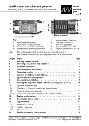
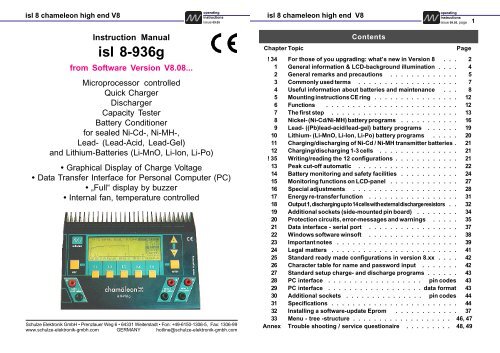
<strong>isl</strong> 8 chameleon high end V8<br />
Instruction Manual<br />
<strong>isl</strong> 8-<strong>936g</strong><br />
from Software Version V8.08...<br />
Microprocessor controlled<br />
Quick Charger<br />
Discharger<br />
Capacity Tester<br />
Battery Conditioner<br />
for sealed Ni-Cd-, Ni-MH-,<br />
Lead- (Lead-Acid, Lead-Gel)<br />
and Lithium-Batteries (Li-MnO, Li-Ion, Li-Po)<br />
operating<br />
instructions<br />
issue 09.05, page<br />
• Graphical Display of Charge Voltage<br />
• Data Transfer Interface for Personal Computer (PC)<br />
• „Full“ display by buzzer<br />
• Internal fan, temperature controlled<br />
<strong>Schulze</strong> <strong>Elektronik</strong> <strong>GmbH</strong> • Prenzlauer Weg 6 • 64331 Weiterstadt • Fon: +49-6150-1306-5, Fax: 1306-99<br />
www.schulze-elektronik-gmbh.com GERMANY hotline@schulze-elektronik-gmbh.com<br />
<strong>isl</strong> 8 chameleon high end V8<br />
Contents<br />
operating<br />
instructions<br />
issue 09.05, page<br />
Chapter Topic Page<br />
! 34 For those of you upgrading: what’s new in Version 8 . . . 2<br />
1 General information & LCD-background illumination . . . . 4<br />
2 General remarks and precautions . . . . . . . . . . . . . 5<br />
3 Commonly used terms . . . . . . . . . . . . . . . . . . . 7<br />
4 Useful information about batteries and maintenance . . . 8<br />
5 Mounting instructions CE ring . . . . . . . . . . . . . . . . 12<br />
6 Functions . . . . . . . . . . . . . . . . . . . . . . . . . 12<br />
7 The first step . . . . . . . . . . . . . . . . . . . . . . . . 13<br />
8 Nickel- (Ni-Cd/Ni-MH) battery programs . . . . . . . . . . . 16<br />
9 Lead- ((Pb)lead-acid/lead-gel) battery programs . . . . . . 19<br />
10 Lithium- (Li-MnO, Li-Ion, Li-Po) battery programs . . . . . 20<br />
11 Charging/discharging of Ni-Cd / Ni-MH transmitter batteries . 21<br />
12 Charging/discharging 1-3 cells . . . . . . . . . . . . . . . 21<br />
! 35 Writing/reading the 12 configurations . . . . . . . . . . . . 21<br />
13 Peak cut-off automatic . . . . . . . . . . . . . . . . . . . 22<br />
14 Battery monitoring and safety facilities . . . . . . . . . . . 24<br />
15 Monitoring functions on LCD-panel . . . . . . . . . . . . . 27<br />
16 Special adjustments . . . . . . . . . . . . . . . . . . . . 28<br />
17 Energy re-transfer function . . . . . . . . . . . . . . . . . 31<br />
18 Output 1, discharging up to 14 cells with external discharge resistors . . 32<br />
19 Additional sockets (side-mounted pin board) . . . . . . . . 34<br />
20 Protection circuits, error-messages and warnings . . . . . 35<br />
21 Data interface - serial port . . . . . . . . . . . . . . . . . 37<br />
22 Windows software winsoft . . . . . . . . . . . . . . . . . 38<br />
23 Important notes . . . . . . . . . . . . . . . . . . . . . . . 39<br />
24 Legal matters . . . . . . . . . . . . . . . . . . . . . . . . 41<br />
25 Standard ready made configurations in version 8.xx . . . . 42<br />
26 Character table for name and password input . . . . . . . 42<br />
27 Standard setup charge- and discharge programs . . . . . . 43<br />
28 PC interface . . . . . . . . . . . . . . . . . . pin codes 43<br />
29 PC interface . . . . . . . . . . . . . . . . . . data format 43<br />
30 Additional sockets . . . . . . . . . . . . . . . pin codes 44<br />
31 Specifications . . . . . . . . . . . . . . . . . . . . . . . . 44<br />
32 Installing a software-update Eprom . . . . . . . . . . . . 37<br />
33 Menu - tree -structure . . . . . . . . . . . . . . . . . . . 46, 47<br />
Annex Trouble shooting / service questionaire . . . . . . . . . 48, 49<br />
1
<strong>isl</strong> 8 chameleon high end V8<br />
operating<br />
instructions<br />
issue 09.05, page<br />
34 for those of you upgrading: what’s new in Version 8<br />
We know that it is precisely you who can’t wait to charge your Lithium batteries, and anyway you<br />
already know how to operate the charger. However, there are differences, and that’s why the last<br />
section is right here, at the start:<br />
To avoid having to carry out any conversion work on the charger at the same time as introducing V 8 of the<br />
software, we have limited the maximum cell count of battery output 3 for Li-Io and Li-Po cells to two.<br />
Though we are able to say that the <strong>isl</strong> 8 can be updated only by changing an EPROM and making some<br />
verifying measurements (also by yourself), you should send your charger to Weiterstadt. We will re-calibrate<br />
your charger because in the most seldom cases the old calibration is good enough to charge lithium cells.<br />
Additionally we will update the hardware for more reliability (cue: product care).<br />
Please note the following additional points:<br />
• 1. INFORMATION AND WARNING:<br />
After fitting the new EPROM check the charge voltage at Battery 3 (Akku 3): Both - 1 and 2 Li-Po<br />
cells - setting. Charge at around 250 ... 300 mA. Repeat the same test (or charge simultaneous)<br />
with packs of 1, 2, 3, 4 .. 10 Li-Po cells, connected to the Battery 1 and Battery 2 outputs.<br />
When the selected charge current is reached, please connect a digital voltmeter in parallel to the<br />
Battery sockets and check that it reads the same charge voltage (accurate to +-1%) as appears on<br />
the screen of the <strong>isl</strong> 8 (selection see below).<br />
(Remember: 1% at 8.4 volts are +-84mV, i.e. a display of 8.316 to 8.484 volts are ok; at 30 volts it is<br />
+-300 mV, i.e. display voltages of 29.700 V to 30.300 V are ok).<br />
If the readings do not agree, the charger needs to be re-calibrated. Please return it to us at<br />
Weiterstadt for the work to be carried out. If the necessary pecision can not reached by<br />
calibration, the microprocessor has to be changed at your costs (sorry).<br />
-->> To display the three charge voltages with an accuracy of one millivolt select "refresh" of the<br />
battery 2 output (Battery voltages of pack 1, pack 2 pack 3 are shown one below the other). The<br />
digital voltmeter you use for this measurement must have an error of better than 0.3%. If you changed the Version 8 EPROM at home (or if the calibration get lost), the display shows<br />
a warning message that the <strong>isl</strong> 8 is not calibrated. You do not have any possibility to switch off this<br />
warning - because we have no influence in the precision of your control measurements described<br />
above. Only a calibration in our firm deletes the warning message.
<strong>isl</strong> 8 chameleon high end V8<br />
1 General information<br />
operating<br />
instructions<br />
issue 09.05, page<br />
Congratulations! With the <strong>isl</strong> 8-<strong>936g</strong> you have purchased a top of the line product made in Germany.<br />
Reliable SMD technology, outstanding performance and flexibility and last but not least their easy<br />
handling have made the previous models very popular. By adding the most up-to-date electronic<br />
devices, a third charge output and a modified discharge circuit which re-transfers energy into the<br />
car battery, the chameleon high end has become even more powerful and flexible.<br />
The <strong>isl</strong> 8-<strong>936g</strong> requires no maintenance, but needs to be protected against dust and moisture. Openings<br />
in the housing are essential for cooling and must not be blocked! The chameleon high end provides<br />
best operating comfort and maximum reliability. Using the automatic C charging option, you will notice<br />
that the <strong>isl</strong> 8 microprocessor will charge you batteries as fast as possible, yet as carefully as<br />
necessary (don't be worried about the relatively high start current of the Ni-MH current calculation<br />
automatic). All three outputs may be in use at the same time. Additionally you can discharge your<br />
batteries, measure their capacity and condition them. Same options are available for sintered Ni-Cd,<br />
Ni-MH batteries.<br />
The big graphical LCD (Liquid-Crystal-Display) panel provides user guidance via softkey-functionbuttons<br />
and allows the transfer of charge data and parameters to a personal computer either online<br />
or from the non-volatile memory.<br />
In order to make full use of your new charger we strongly recommend you to read the Instruction<br />
Manual page by page and take note of the hints. Although the supplied text is rather long, there<br />
is valuable information in each sentence.<br />
Note: In order to get to a certain point in the menu, you may have to change the screen several<br />
times. Therefore in this manual you will sometimes find the complete sequence of key-operations,<br />
including the appropriate screen text, starting from the initial powerOn display.<br />
You will find in Chapter 33 (MenueTreeStructure) an overview of the available function-key<br />
descriptions.<br />
Note: As a novelty of the <strong>isl</strong> 8 - 2005 series the display background is illuminated.<br />
You will hear a humming sound when the backlighting of your <strong>isl</strong> 8 is switched on; this is perfectly<br />
normal. It simply indicates that the 400 Hz voltage converter for the lighting is operating. The<br />
illuminated film acts (unwanted) as a “loudspeaker”.<br />
We now deliver the <strong>isl</strong> 8 with a modification that you can switch on and off the illumination.<br />
Since the circuit board does not include a separate On / Off switch for this purpose, we have<br />
pressed an existing one into service: the switch for the fan socket on the side of the case.<br />
The button marked “f1 - fan” can now be used to switch off the backlighting (together with the fan<br />
for the battery cooler) in the graphic screen displays for “pack 1”, “pack 2” and “pack 3”.<br />
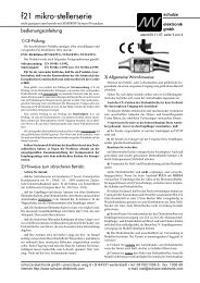
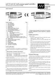
Re chapter 5 : Mounting instruction CE-ring<br />
Additional parts:<br />
CE-kab-i8<br />
not included<br />
CE-ring<br />
3 x included<br />
4<br />
<strong>isl</strong> 8 chameleon high end V8<br />
2 General remarks and precautions<br />
operating<br />
instructions<br />
issue 09.05, page<br />
The CE marking which you will find on all schulze products indicated that the equipment has been tested<br />
to meet the stringent European safety and radiation requirements; this does not mean that you do not<br />
have to follow these instructions!<br />
The cooling fins at the rear of the charger have been precision extruded and then machined; they may<br />
have sharp edges; handle with the same care with which this equipment has been manufactured.<br />
Please remember that fast-charging batteries can push the batteries to their limit; never operate the<br />
chargers unattended. The charger as well as the batteries may get warm; when in use, they should be<br />
placed on an appropriately sized, non-heat-conducting and non-combustible surface. By following these<br />
rules extensive damage will be avoided in case of a mishap. This applies in the same way also for<br />
the attached batteries.<br />
Many modern transmitters are equipped with an internal reverse-voltage protection diode. No “smart”<br />
charger can fast-charge these transmitters unless this diode is bypassed (shunted) (see chapter 11 for<br />
additional information when charging transmitters). Preferably, you can remove the transmitter’s battery<br />
and fast-charge it outside the transmitter. If you want to bypass the diode, contact the transmitter<br />
manufacturer. In no case should the fast-charge current for a transmitter pack exceed 1.2 Amp.<br />
In order to keep possible damages small in the case of an error, we recommend strongly to remove the<br />
batteries from the transmitter!<br />
Do not modify the charger’s car battery power cables or connecting clamps; they are very low loss to<br />
support the charger’s high-end charge capabilities. Do NOT insert fuses and NOT plug the charger into<br />
the car´s cigarette lighter!<br />
Do not cross-connect individual output charge cables or wires thereof; each charger outlet has its own<br />
sensing circuitry. Prevent electrical contact between any charger outlet and your car’s body. All this<br />
may damage your charger and/or your batteries! It is safest to place the charger on the ground. Place<br />
the charger on a safe support, do not “hang” it somewhere under the hood. The best approach is to use<br />
a separate, fully charged, dedicated 12-V battery and take it to the flight line.<br />
The internal software is always checking for operational errors.<br />
Do not operate the charger in the case that any of the cables are damaged or frayed, or in case the display<br />
panel indicates an ERROR.<br />
The <strong>isl</strong> 8 charging devices operate on 11 to 15 VDC, but may only be connected directly to a 12 V car<br />
battery! DO NOT RUN YOUR ENGINE OR ATTEMPT TO CHARGE YOUR CAR BATTERY WITH<br />
EXTERNAL EQUIPMENT WHILE OPERATING THE CHARGER, OR AS LONG AS THE CHARGER IS<br />
HOOKED UP TO YOUR CAR’S BATTERY.<br />
Should you decide to operate the charger from a (110V/240V AC to 12V or 13.8V DC) power supply<br />
(“battery eliminator”), then make sure this power supply is well regulated, can supply continuous DC<br />
current as high as 40 ... 45Amps(!), has a very high output capacitance (>5000µF/16V), very low ripple<br />
and is insensitive to the frequency of the carger´s internal switching voltage converter. Using any other<br />
source is likely to damage your charger or your batteries, and voids the warranty. ALWAYS use a<br />
schulze nt-40A power supply, NEVER use an automotive battery charger as the source for the<br />
precision-engineerd schulze charger.<br />
Because of the high charge current capabilities of these chargers, you should always use high-quality,<br />
gold-plated connectors in the charge cables to your batteries. Also, use heavy-duty (12-g) flex wire.<br />
We recommend you use either schulze short circuit protected charging cables and/or (in the USA) 4<br />
mm bullet connectors, the Deans Ultra plug or similar. See you local hobby dealer or call R/C-Direct.<br />
Always connect the banana plugs of your charge cables first; then, connect the charge cable to the<br />
battery. Note that “open” banana plugs, when the charge cable and battery are connected, carry the full<br />
battery voltage (and current).<br />
Note that all chargers have ventilation holes. Especially in discharge mode or when charging batteries less<br />
than 12V, the charger will dissipate energy, and thus get warm (the <strong>isl</strong>-8 even has an internal cooling<br />
fan). Do not block these ventilation holes and make sure you allow free air flow through the cooling fins<br />
5
<strong>isl</strong> 8 chameleon high end V8<br />
operating<br />
instructions<br />
issue 09.05, page<br />
located at the rear of the charger.<br />
Protect the charger from direct exposure to the sun (the sun´s heat will temporarily turn the LC-display<br />
black), dust, moisture and rain(!).<br />
Even though the schulze chargers are smart (they are micro-processor equipped and can determine a<br />
battery’s number of cells and its optimum charge current pattern), attempting to charge the following<br />
packs should not be attempted:<br />
- batteries built up from cells of different types and capacities<br />
- batteries made from different types of single cells<br />
- batteries with a different charging level of the cells<br />
- non rechargeable cells (dry cells)<br />
- batteries which are not expressly designed for fast charging and recharging.<br />
- defective or damaged packs or cells<br />
- already fully charged and/or hot batteries<br />
- battery packs with internal charge-current limiting devices<br />
- batteries which are buildt-in (internal) to other equipment<br />
Do not exceed a battery’s design (maximum) charge current as specified by its manufacturer; note that<br />
the schulze chargers will still optimally charge these packs in automatic charging mode; you can<br />
program the charger’s max (limit) charge current.<br />
When charging high-capacity battery packs with less than 7 cells, exercise extra care to make sure that<br />
these are not over-charged; packs which are (too) deeply discharged may cause the charger to cut off<br />
too soon.<br />
New batteries will only achieve their maximum capacity after several charge/discharge cycles; schulze<br />
chargers can be programmed to provide these cycles automatically.<br />
Always verify the charge amount which your battery has absorbed (mAh or Ah) after a full charge (this is<br />
indicated on the display panel); this is probably the best gauge of a battery’s health and/or the proper<br />
operation of the charger. This way, you will avoid unexpected loss of power and/or control.<br />
Please remember that battery packs can heat up considerably during a high-current discharge cycle;<br />
program your charger’s max discharge current to prevent overheating of the packs unless you provide<br />
additional cooling (some of the racing pilots now use a tube with electric fan cooling!). Note that e.g.<br />
discharging a 27-cell 1000mAh battery at 5A (=5C rate) will dangerously overheat this battery; the<br />
schulze charger can (and) should in this case be programmed to the limit discharge rate to a more<br />
acceptable level, for instance 1A (=1C) and/or a battery cooler in combination with the temperature<br />
sensor for cut-off must be used. You can also use our build in low-temperature-start circuit. (Do not<br />
forget to activate temperature sensor to the right pack output and fix it at the right battery.)<br />
An additional important function is the selection of the automatic cut-off circuit. Read the important<br />
comments in Chapter 12). Maximum protection against malfunctions of the cut-off automatic is provided<br />
by selecting additional cut-off criterias like max. temperature, max. energy input and max. charge time.<br />
Warranty on your new schulze charger is one year after the date of first purchase. Expressly excluded<br />
from this warranty are failures due to incorrect use and/or damage(s) to any object(s) and/or person(s)<br />
resulting from the correct or incorrect use of this charger. Before returning a schulze charger for<br />
repair, please check the charging of a single battery pack using a fully charged car battery; go through<br />
the check list at the end of the operating manual; if you still have problems, then, add a description of the<br />
problem you encountered (ALWAYS fill out the annex SQ-service questionaire), proof of purchase<br />
(date), your address and your telephone number.<br />
Warranty repairs are performed in Germany or in the USA; out-of-warranty work will performed at same<br />
locations, for a nominal charge. Return units which are found to be in good operating condition will be<br />
subjected to normal manufacturing tests. There will be a nominal charge for this, wether the unit is in<br />
warranty or not.<br />
More than a thousand schulze chargers are in use around the world every day without any problems.<br />
They perform….again and again.<br />
We hope that you, too, will join this happy schulze family.<br />
6<br />
<strong>isl</strong> 8 chameleon high end V8<br />
3 Commonly used Terms<br />
operating<br />
instructions<br />
issue 09.05, page<br />
Final charge voltage: the voltage at which the battery's charge limit (capacity limit) is reached.<br />
The charge process switches from a high current to a low maintenance rate (trickle charge) at<br />
this point. From this point on further high current charging would cause overheating and<br />
eventual terminal damage to the pack.<br />
Final discharge voltage: the voltage at which the battery's discharge limit is reached. The<br />
chemical composition of the batteries determines the level of this voltage. Below this voltage the<br />
battery enters the deep discharge zone. Individual cells within the pack may become reversepolarised<br />
in this condition, and this can cause permanent damage.<br />
Memory effect: The real memory effect has been recorded by Nasa, caused by repeated<br />
charge / discharge cycles. Nasa has found that full capacity can be regained by<br />
overcharging the cells. In modelling applications different effects are responsible<br />
for the reduction in cell capacity. The problem can be cured by balancing the cells<br />
(see below), and prevented by the measures described in Chapter 4.1.3.<br />
Balancing: a method of regaining full (nominal) capacity by alternately charging and discharging<br />
the pack, sometimes several times. This process is especially useful after a long period of nonusage<br />
(e.g. after purchase, or after several weeks without flying), and is also used to disperse<br />
the memory effect (see below). The effect of balancing is to break down the coarse crystaline<br />
structure (low capacity) inside the cell and convert it into a fine crystaline one (high capacity).<br />
Power-On (- reset): the status of the <strong>isl</strong> 8 after it has been connected to the car battery.<br />
Ready message: charger ready to run the program you have just selected (batteries not<br />
connected). The display shows #GO#.<br />
C: Coulomb or capacity: Unit of measurement relating to the quantity of charged energy. In<br />
conjunction with charge current data this unit is used to determine the recommended / prescribed<br />
charge current of a battery of a given capacity. Example: if the charge or discharge<br />
current of a 500 mAh battery is 50 mA, we refer to this as a charge or discharge at one tenth C<br />
(C/10 or 1/10 C).<br />
A, mA: unit of measurement relating to charge or dis-charge current. 1000 mA = 1 A (A=Ampere,<br />
mA=Milliampere)<br />
Ah, mAh: unit of measurement for the capacity of a battery (Amperes x time unit; h = hour). If a<br />
pack is charged for one hour at a current of 2 A, it has been fed 2 Ah of energy. It receives the<br />
same quantity of charge (2 Ah) if it is charged for 4 hours at 0.5 A, or 15 minutes (=1/4 h) at<br />
8A.<br />
7
<strong>isl</strong> 8 chameleon high end V8<br />
4 Useful information about batteries and maintenance<br />
4.1.1 General information<br />
operating<br />
instructions<br />
issue 09.05, page<br />
Do not charge below 0°C, optimum is 10...30°C.<br />
A cold cell is not capable of accepting as much current as a warm one. For this reason you must<br />
expect differences in charge characteristics if you use fully automatic charge current calculation<br />
(in Winter the charging properties will be worse than in Summer). The best working temperature<br />
for a Ni-MH cell is 40 ... 60°C. At lower temperatures the cell can not supply higher<br />
currents. Caution when using those cells a a receiver battery in a helicopter in the wintertime.<br />
The lower the internal resistance of the battery, the higher the charger can increase the charge<br />
current for that battery. For a battery charger which sets the current automatically the<br />
resistance of the cable is added to the internal resistance. For this reason: use<br />
heavy cable (large cross-section), even for receiver batteries, and keep them short.<br />
Do not charge via a switch or switch harness!<br />
If you wish to measure battery capacity accurately a suitable discharge current is usually 1/10 C.<br />
4.1.2 Reflex charging<br />
Charging processes which include a brief discharge pulse definitely have the effect that the<br />
battery is several degrees cooler at the end of the process. However, from the point of view of<br />
the competition operator this is an undesirable effect, as the cell chemistry can only supply high<br />
currents if its temperature is raised to a certain extent.<br />
All these effects, whether they actually occur or are simply hear-say, have no practical<br />
significance if batteries are correctly handled in the first place. When a battery is<br />
full, you can’t fill it any fuller! Read also chapter 4.1.3 for this subject area.<br />
4.1.3 Memory effect of Ni-Cd & Ni-MH cells<br />
If cells are repeatedly stored partially discharged, or are recharged from a half-discharged state,<br />
what is known as the memory effect sets in. The cells note that their full capacity is not<br />
required, and react by refusing to make it available.<br />
One aspect of this is that the crystalline chemical structure inside the cell changes; the cell‘s<br />
resistance rises and its voltage collapses under load, with the result that “full capacity” can no<br />
longer be exploited at normal discharge currents.<br />
Even if reflex charging were to eliminate the memory effect, there is no denying the necessity to<br />
store your cells in the discharged state; this applies to Ni-Cd cells and also to Ni-MH cells.<br />
A characteristic fact of these cells is that they self-discharge - and the rate of self-discharge is<br />
different for each individual cell in a battery pack! If a fully charged pack is left for a considerable<br />
time, it will eventually consist of cells of widely varying states of charge.<br />
If at this point you ...<br />
a) ... give the pack a full charge: the cell with the highest charge will be overcharged, heat up<br />
and be ruined, while the cell with the least charge will still not be full after the same period of<br />
charging.<br />
b) ... discharge the pack: the cell with the least charge will be completely flat first, then reverse<br />
polarity and often suffer an internal short-circuit. At the point when this happens, the cell with<br />
the most charge is still not yet completely discharged.<br />
This is a reliable method of wrecking your most valuable packs - and rest assured<br />
that reflex charging will make absolutely no difference. However, there is one<br />
method of avoiding the problem: discharge cells after use, and recharge them just<br />
before use!<br />
8<br />
<strong>isl</strong> 8 chameleon high end V8<br />
4.2 Nickel-Cadmium-batteries (Ni-Cd)<br />
operating<br />
instructions<br />
issue 09.05, page<br />
Nominal voltage level: 1.2 V / cells.<br />
Selecting the fast charge current (manual setting):<br />
Charge current = 2 C (never less!) (C=nominal battery capacity). Otherwise the cells do not make a<br />
detectable peak and the peak cut off automatic is not able to work resp. to work reliable.<br />
Maximum continous discharge current:<br />
Currents of 10 C to 30 C are possible, depending on cell type.<br />
Long time storage:<br />
Empty i.e. discharged to the discharge voltage cut off level (see maintenance), at low temperature<br />
(-20°C to +10°C).<br />
Maintenance: Charging: The automatic current setting circuitry (patent applied for) provides optimum<br />
protection to your Ni-Cd batteries during charging. The reduced current towards the end of the<br />
charge ensures a completely full pack combined with only a slight temperature rise, as you will<br />
easily see in comparison with conventional constant current techniques.<br />
Do not use the automatic charge current calculation of the Ni-Cd batteries when charging Ni-MH batteries!<br />
Discharging: To prevent your cells from memory effect and to keep the full capacity you have to<br />
discharge it after use, even when you store it over night (select Auto-D program to discharge down<br />
to 0.85V / cell).<br />
If a battery is brand-new or used irregularly it is often only possible to balance it completely by<br />
carrying out several discharge - charge cycles. Amongst model car operators it is standard practice<br />
to erase any memory effect by completely discharging each cell individually via a resistor (approx.<br />
68 Ohm). This deliberately ”unbalances” the pack, but it can cause the automatic charge termination<br />
circuitry to switch off the current prematurely during the charge process. Remedy: Discharge<br />
with a 10 Ohm resistor in series to a 1 A diode (1N4001).<br />
For receiver batteries special types such as the Sanyo KR500AAEC / N500AC (lower resistance) are a<br />
good choice.<br />
Warning: The reduced charge current with 1-6 cells makes the voltage peak in the charge curve very<br />
slight, especially with batteries of high nominal capacity. In this situation the charger is sometimes<br />
unable to detect the ”full” condition due to the ill-defined peak.<br />
4.3 Nickel-Metal-Hydride batteries (NiMH)<br />
Voltage level: 1.2 V / cell.<br />
Selecting the fast charge current manually (not automatically):<br />
Charge current typical 1 C (never less!) (set a fixed current of, for example, 1.2 A with 1100 mAh<br />
batteries, or 3 A with 3 Ah cells). Otherwise the cells do not make a detectable peak and the peak<br />
cut off automatic can not work reliable. Some modern high-current Ni-MH cells made by particular<br />
manufacturers can safely be charged at a higher rate of up to 1.6 C (Panasonic 3000: 3,5 - 4A, GP<br />
3000/3300: 3 A, Saft 3000: 3 A (not if battery is charged inside a transmitter!), Sanyo 3000/3300: 4 - 5A).<br />
Because of its high internal resistance do not charge high capacity cells of mignon(AA)-size from<br />
1500 mAh upward with automatic current calculation (AutoC, -CD, -DC).<br />
Maximum continous discharge current:<br />
Currents of 5 C to 15 C are possible, depending on cell type.<br />
Long time storage:<br />
Empty, i.e. discharged to the cut off level (see maintenance), at low temperature (-20°C to +10°C).<br />
Maintenance: To protect your Ni-MH batteries from the memory effect and keep the full capacity,<br />
discharge the cells after use down to the discharge voltage limit even when you store it over night.<br />
Never discharge by car bulbs or the drive motor (premature charge termination!), but use only the<br />
Auto-D programm when the battery type Ni-MH is selected. The cut off voltage is 1 volt / cell. This<br />
eliminates the danger of deep discharge termination and polarity reversal (over-discharge).<br />
It is important that you take the trouble to give Ni-MH cells when storing at +10...30°C a charge /<br />
discharge cycle around every four weeks, otherwise they become tired, and have to be pampered<br />
9
<strong>isl</strong> 8 chameleon high end V8<br />
operating<br />
instructions<br />
issue 09.05, page<br />
to restore them to full vigour. This involves going through the tiresome business of many repeated<br />
charge / discharge cycles.<br />
The automatic current setting circuitry (patent applied for) provides optimum protection to your Ni-MH<br />
batteries during charging. Do not use the Ni-Cd automatic current selection for Ni-MH batteries!<br />
Warning: Never charge fully charged Ni-MH batteries with the Auto C (or ..CD programs): Overheating<br />
and danger of explosion! The cut off automatic is disabled for about the first 7 minutes<br />
of charging - this could lead to a minimum charge time of about 10 minutes!<br />
It is possible to erase any memory effect by discharging each cell individually via a resistor of approx.<br />
10 Ohms in series to a 1 amp silicon diode (0.7 volt) plus a 1 amp Schottky diode (0.3 volt).<br />
Warning: At lower cell counts (1-6) and low charge currents (below 2 C) the battery makes only a very<br />
low voltage peak when fully charged. Under those conditions the cut off automatic works less<br />
reliable then with higher currents and/or higher number of cells.<br />
Typical for Sanyo Twicell industry types with flat top and RC3000H cells:<br />
High maximum load capacity and voltage level.<br />
Typical for Panasonic P3000NIMH cells:<br />
High maximum charge capacity and voltage level.<br />
Typical for GP GT3000 / 3300 cells:<br />
Extremely high charge capacity, good voltage level.<br />
Can be discharged with medium currents (about 40...45 amps; from 2003 up to 60 amps).<br />
4.3 Lead-acid batteries (Pb) ...<br />
... and VRLA (valve regulated lead-acid batteries = lead-gel batteries)<br />
Nominal voltage level: 2.0 V / cell.<br />
Charge voltage level: 2.3 V / cell; 2.42 V / cell for 3 hours max.<br />
Min. discharge voltage: 1.7 V / cell (this reduces lifetime).<br />
Number of cells to be selected on the <strong>isl</strong> 6:<br />
Nominal voltage of the battery to be charged divided by the nominal voltage level of lead-acid<br />
battery cells = cell count.<br />
Example: 12 V-Lead acid battery divided by 2,0 V => 6 cells.<br />
Selecting the fast charge current:<br />
Charge current = 0.15 C (C = nominal battery capacity) if no data sheets are available.<br />
Charge current up to 0.4 C for special types.<br />
Maximum continous discharge current:<br />
Typically 0.2 C, short time load up to 1 C.<br />
Long time storage:<br />
Full at low temperature, more precise:<br />
At +10°C up to 12 month, at +10...20° max. 9 month, at +20...30°C max 6 month, at +30...40°C 3<br />
month.<br />
Charge again after this period.<br />
Maintenance: In contrast to Ni-Cd/Ni-MH batteries, lead-acid batteries must be fully recharged<br />
after use in order to maintain full capacity.<br />
The nominal capacity can be reduced very quickly by incorrect handling (overloading, repeated<br />
100% discharges, and especially by deep-discharges). Please observe the battery manufacturer’s<br />
recommendations.<br />
Typical: The characteristics of lead-acid batteries are quite different to those of the Ni-Cd sealed<br />
cell packs which are used as the power source in model aircraft, cars and hydro-boats. They<br />
can only tolerate relatively low currents relative to their capacity if their full capacity is to be<br />
exploited, and/or the voltage is not to collapse too far.<br />
Used as single-cell glowplug energiser batteries and power source in some scale boats.<br />
Low self-discharge rate.<br />
10<br />
<strong>isl</strong> 8 chameleon high end V8<br />
4.5 Lithium-Manganese-Oxide batteries (LiMnO)<br />
operating<br />
instructions<br />
issue 09.05, page<br />
Nominal voltage level: 3.0 V / cell.<br />
Selecting the fast charge current: Up to 0.3125 C, dep. on cell type.<br />
Maximum continous discharge current: Up to 1.5 C.<br />
Maintenance: Always store these cells in the charged state.<br />
Typical: These cells are particularly recommended as receiver batteries (2 cells required),<br />
although correct charging and storage are very important. However, we do not recommend<br />
them as slow-fly flight packs, since they have a limited ability to supply high currents, and their<br />
useful life varies greatly according to the discharge current and the extent to which they are<br />
discharged. Very good weight : energy ratio.<br />
Hint: The most common form of this cell type is the „Tadiran“ cell.<br />
Tip: Ideally all single cells in a pack should be charged separately; alternatively charge all cells in parallel.<br />
4.6 Lithium-Ion batteries (Li-Io & Li-Po):<br />
Nominal voltage LiIo: 3,6 V / cell (SAFT)<br />
Nominal voltage LiIo/LiPo: 3,7 V / cell (SANYO, KOKAM)<br />
Max. charge voltage LiIo: 4,1 V +-40mV / cell (SAFT)<br />
(absolute limit 4.3 V / cell) LiPo: 4,2 V +-50mV / cell (MoliCel)<br />
Min. discharge voltage LiIo: 2,5 V / cell (MoliCel), 2,7 V / cell (SANYO)<br />
(absolute limit 2.3 V / cell) LiPo: 3,0 V / cell (KOKAM)<br />
Number of cells to be selected on the charger:<br />
Nominal voltage of LiPo-pack div.by nominal cell-voltage = cell count.<br />
--> 11,1 V LiPo-pack divided by 3.7 V => select 3 cells!<br />
If you would select more cells, the pack would explode during charging!<br />
Example: The Thunderpower TP8200 3s4p pack consists of 12 cells.<br />
4 of 2050mAh are connected parallel (4p) -> 4 * 2,05 Ah = 8200mAh.<br />
3 of the paralleled cells are connected in series (3s)-> 3*3,7V= 11,1 V.<br />
Selecting the fitting cell type:<br />
Select that battery type from the <strong>isl</strong> 8 menue which characteristics match best with the data<br />
sheet of the battery manufacturer.<br />
Selecting the fast charge current:<br />
Charge current = 1 C (SANYO / KOKAM) or less (0,7 C PANASONIC) (C = nominal battery<br />
capacity).<br />
Maximum continous discharge current:<br />
1 ... 20 C (very new types), depending on cell type.<br />
Long time storage:<br />
Empty, i.e. discharged to the discharge voltage cut off level (see maintenance), at low temperature<br />
(-20°C bis +10°C).<br />
Maintenance: Discharge with up to 1 C down to above listed discharge voltages. Always store<br />
these cells in the discharged state, if stored fully charged, the result can be a permanent<br />
reduction in capacity.<br />
When stored at +40°C or more charge additional every two months.<br />
Typical: Very good weight : energy ratio. High load cells have also a good weight : power resp.<br />
performance ratio.<br />
Hint: Many manufacturers direct how many cells are allowed to use in series and/or parallel use.<br />
The exact technical term of a Li-Po cell is Lithium-Ion-Polymer battery. These are hybrid cells and<br />
contain gelled electrolyte to enhance ion conductivity. The "true" (dry) Lithium-Polymer cells<br />
suffers from poor conductivity and work only with higher temperatures of more than 60°C.<br />
11
<strong>isl</strong> 8 chameleon high end V8<br />
5 Mounting instructions CE ring<br />
operating<br />
instructions<br />
issue 09.05, page<br />
Use 2.5 mm2 cables, 1 cable red, 1 cable black.<br />
Solder 1 male socket at every end of cable.<br />
Slide ring from free end of cables to 4 cm ( 2") to the male sockets and fix it with your<br />
fingers. Make additional 3 windings through the center of the ring.<br />
Cut cables to 15 cm, if cables at the pack have 5 cm (Max. total length 20 cm).<br />
The cables now looks like those of the picture on page 4.<br />
Bind cables with short pieces of heat shrink tubes.<br />
Solder your connectors on to the free ends of the cables now.<br />
You can also use our pre-fabricated charge cables CE-kab-i8.<br />
6 Functions<br />
Charge- and discharge programs of Pack 1 are split into groups, which can be selected<br />
using the +/- buttons after you have pressed f2/3/4:pack1/2/3param and f2:Progrm.<br />
The charger will perform the option you select by pressing the enter button. All programs<br />
use those currents as their maximum, which were separately selected under Ccurr<br />
and D-curr in the first and second parameter screen.<br />
[*] not at battery 2 output (Akku2), [**] only selectable on battery 3 output (Akku 3)<br />
2 fixed current combination programs* fix_CD, fix_DC, (up to 5 times)<br />
2 automatic current calulation combin.programs* auto_CD, auto_DC, (up to 5 times)<br />
1 fixed current charge programm fixC,<br />
1 fixed current discharge programm* fix-D,<br />
1 automatic current calulation charge program autoC,<br />
1 automatic current calulation discharge program* autoD,<br />
div. maximum currents [Amps] 0.1, (0.15, 0.2**), 0.25, 0.3, 0.5, 0.4, 0.6, 0.8, 1.0, 1.2, 1.5 (A3) ,<br />
2.0, 2.5, 3.0, 3.5, 4.0, 4.5, 5.0 (A2) , 5.5, 6.0, 6.5, 7, 8, max.(10) (A1)<br />
The actual charge current may also vary with battery type, number of cells, battery<br />
condition etc.<br />
The discharge current on akku 3 output is max. 400mA.<br />
Note regarding these instructions:<br />
To move to a particular menu point you may have to navigate your way through several screen<br />
displays.<br />
Sometimes these instructions list the complete path, i.e. a sequence of function buttons which<br />
have to be pressed, together with the associated texts, always starting from the PowerOn<br />
screen.<br />
A summary of the names used for the function buttons can be found in<br />
Chapter 30: Menu Tree Structure.<br />
12<br />
<strong>isl</strong> 8 chameleon high end V8<br />
7 The first step<br />
operating<br />
instructions<br />
issue 09.05, page<br />
• Take the chameleon high end out of the packaging.<br />
See Chapter 2: General Remarks and Precautions. Lack of air circulation may cause overheating.<br />
• Remove the 5 sockets at the left side of the housing (if not packed separately anyway).<br />
• Connect the chameleon high end to the 12 volt power source car battery.<br />
Note: No batteriepacks must be connected to the charger during this procedure. Try to achieve a<br />
good contact to the car battery terminals first time, otherwise you may not get the power-On<br />
screen ("#GO#") on the display. In this case disconnect immediately and retry after about 5<br />
seconds.<br />
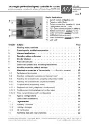
• The LCD panel shows the powerOn Menu screen (powerOn visible at right top) with<br />
the ms-logo and the name of the device <strong>isl</strong> 8-<strong>936g</strong> chamaleon high end plus date and<br />
time.<br />
• Press f2: pack1 to have a look at the screen for Output 1:<br />
The screen will show an empty coordinate-system graph with a horizontal minute<br />
scale and a vertical voltage scale. pack 1 is displayed at top right of the screen.<br />
• Before you connect a batterypack, check the top line of the display (Battery-status)<br />
whether the charge program suits your batteries. The selected charge program is<br />
displayed after the text ready / rdy.<br />
• Before you start testing the unit by charging a battery, please check the top line of<br />
the screen display (battery status display) to ensure that the correct battery type<br />
(e.g. NiCd) is set, and that the charge / discharge program and the maximum permissible<br />
charge / discharge current (in the Parameter menu “below” it) are suitable for your battery.<br />
You will see the selected charge program after the “#GO#”. P.S.: the method of setting this and<br />
other parameters is explained in detail later.<br />
Normally the fully automatic charge program auto L will be the best choice for nickel batteries. The<br />
fully automatic programs will check the battery several times during the charge regarding its<br />
energy consumption ability and adjust the charge current accordingly. Therefore no specific<br />
knowledge about Ni-Cd or Ni-MH cell type and number is required, as long as it is a sintered type<br />
between 100mAh up to some amp-hours (Ah) (Note: at Ni-Cd cells a charge current of min. 2 C,<br />
at Ni-MH-Zellen a charge current of min. 1C must be ensured).<br />
If the charge current stays below 1C (1C=nominal capacity of the battery), the battery is usually<br />
not (or no more) quick chargeable (e.g. high capacity Ni-MH batteries in mignon-size (AA)).<br />
Especially at low cell numbers this may also cause problems for the automatic to detect full<br />
condition. In this case it is advisable to adjust the charge rate manually or even better: Replace<br />
these batteries for other types - if the low curent is not caused by the charge cable or its<br />
connectors.<br />
The fully automatic programs can only perform correctly if the charging leads have adequate<br />
cross sections (2.5 mm 2 - also for Tx- and Rx-batteries!!!) and the cells are soldered<br />
together (i.e.: no spring loaded battery boxes!).<br />
If you want to change the parameters for pack 1, press f2: p1param1. This will open a new submenu<br />
giving the function keys f1 to f5 new meanings and names.<br />
1) It is the f1 button with which you select the battery type. In the second row above the function<br />
keys the display shows the current values which have been set at the factory (or later: the<br />
ones which you had selected).<br />
Pressing the f1: BattType key will create a small field of +-----+ letters in the display showing the<br />
actual battery type.<br />
The descriptions of the key functions will move up like signatures above the windows which is<br />
activated. The bottom line (directly above the keys) will now show the actual functions of the<br />
13
<strong>isl</strong> 8 chameleon high end V8<br />
operating<br />
instructions<br />
issue 09.05, page<br />
esc and enter keys.<br />
Furthermore two arrows point at the +/- keys at the right side. With these keys you can scroll<br />
through all available battery types for Output 1.<br />
After you have found the battery type you want (need!), confirm your selection by pressing enter.<br />
If you won't change the battery type, it is not necessary to scroll back: Just press esc.<br />
The new program will become active after connecting the battery.<br />
When leafing through the Battery Type menu you will have noticed the presence of the items<br />
“write” and “read” in addition to the battery types. This refers to the 12 configurations which<br />
you can store and call up again (see Chapter 25).<br />
All other menue points have also to be operated in this way.<br />
For full batteries with maximum safety the following adjustments are recommended:<br />
(Recommendations shown in bold typing)<br />
2) Program select: f2: Program: Our Proposal for Ni-Cd and Ni-MH batteries: auto C<br />
3) That the program works as you want the individual charge / discharge currents may be<br />
selected manually. The automatic programs will use these manually selected currents as<br />
maximum currents. The range of current may vary during charge/discharge, but will not exceed<br />
the selected maximum current.<br />
Current to select: f3: C-Curr: Our proposal for the autoC charge program: I=max.<br />
4) Number of cells (f4: CellCnt) will indicate 0, as no battery is connected yet. Later during<br />
charging or discharging, the number calculated by the device may be corrected manually.<br />
Now press f5: next Menue to get the next menu screen (p1param2).<br />
5) Next important step in setting up the safety functions is the max. energy input. To charge a<br />
completely empty 2400 mAh cell, usually an energy input of about 2400 ... 2600 mAh is required.<br />
Max. charge input for empty 2400 cells: f2: QUANTmAh: Proposal: 2400mAh.<br />
6) Next safety function is the max. charge time. Charge times in automatic mode will vary depending<br />
on battery type, number of cells, cell condition etc.<br />
With a fully automatic charge program it is only possible to estimate the charge time, and the time<br />
also varies from cell type to cell type. For this reason you must enter the higher value (see<br />
below) if experience does not tell you otherwise. Hint: If the required charge time exceeds 3<br />
hours, something is seriously wrong: either the battery is defective or the charge leads and/or<br />
the connectors are unsuitable.<br />
Max. charge time for Ni-Cd Batteries: f3: TIMEmin: Proposal: 25 ... 45 minutes.<br />
7) Discharge currents at autoD: f3: D-Curr: Proposal: I=max.<br />
8) You must also set the method of working of the automatic charge termination circuit. The setting<br />
which works well for most batteries is:<br />
Peak-Cut-Off: f4: CutOff: normal (for Ni-Cd Akkus), sensit (sensitive: for Ni-MH batteries).<br />
Now press f5: next Menue to get the next menu screen (p1param3).<br />
9) The temperature cut off (f1:Temp.Lim) should be setted to "OFF".<br />
Note: if a temperature sensor is present you can assign it to the various batteries. Please read<br />
Chapter 14 for information on battery monitoring systems. If you have assigned the sensor to a<br />
battery, but the sensor is not connected, you will hear a constant series of warning beeps.<br />
10) Next item in the menu determines the initial program for output 1 when the device is connected<br />
to a power source:<br />
Program at power-on-reset: f2: POR.Prg: Proposal: last or autoC (when you preferably<br />
charge Ni-Cd or Ni-MH batteries at this output).<br />
11) Charging of transmitters with build-in discharge protection diode: f3: w.Diode: select: „OFF“.<br />
12) Finaly you can decide whether you want to use short discharge pulses during charge. This<br />
methode is recommended to re-activate ´tired´ batteries. This method should be most useful with<br />
14<br />
<strong>isl</strong> 8 chameleon high end V8<br />
operating<br />
instructions<br />
issue 09.05, page<br />
Tx- and Rx- batteries which are never completely discharged. However, using this process<br />
does not even out the varying self-discharge rates of individual cells in the pack, and does not<br />
cause the cells to hold more charge, so the use of the function is purely a matter of taste …<br />
Refresh charge: f5: refresh: Proposal: OFF.<br />
Please check also the menue for the battery 2 output. You do not find so much menue points<br />
because of the missing discharge possibility.<br />
By playing with the keys without any batteries connected you get to know the <strong>isl</strong> 8. The selection<br />
of functions and the variation of values is always the same. If you are looking for a certain<br />
function, please use the Menu-Tree-Structure for reference (Chapter 33).<br />
- The esc key will always lead you back to the powerOn Menu screen without changing<br />
any values! In those cases when no values will be selected you can also get back to the<br />
battery screens (pack x) by pressing the enter push-button.<br />
From the powerOn Menu screen press f5 twice (f5:i8param1, f5:i8param2) and then f4<br />
(f4:name) if you want to add a personal word/name.<br />
Default on delivery is the name schulze elektronik gmbh with a “v” acting as cursor above the<br />
first letter "s".<br />
Other standard values can be called up with the function keys on the right side<br />
(date: 15. 6.95, time: We 12:30, copy: buffer1 to memory ...).<br />
Use f2 and f3 to move the cursor left or right. f1 and f4 will delete the letter below the cursor before<br />
it will move to the next position. To change the letters use the +/- key, marked with sign select.<br />
Press enter to store the new name in the non-volatile memory of the <strong>isl</strong> 8, or press esc to clear all<br />
changes and leave this sub-menu.<br />
Note: If a menu item on the display appears inverse (black background), the appropriate function key<br />
is temporarily blocked (i.e.: during test phase of Pack 1).<br />
If temperature value appears inverse, battery is not assigned and temperature-cutoff is deactivated.<br />
A ‘*’ in front of a menu item indicates, that this function is not available yet, but may be activated during<br />
a future software update.<br />
Back to the pack 1 screen:<br />
• The program which is displayed in the top line will start after the battery is connected.<br />
The charge amount will be continuously updated right next to the program / current display. Next to<br />
it you can see the temperature, measured via a connected sensor. At present this is for information<br />
only and can not be used for temperature cut-off purposes.<br />
On the right side of the display, below the car battery voltage (inverse for better contrast) the status<br />
of the other two charge Outputs is shown.<br />
• A Full indication or the disconnection of a battery will automatically cause a change to the<br />
appropriate screen to show this event. The name of Pack x (inverse) can be seen in the<br />
right top corner of the screen.<br />
Temporarilly connect a battery to Output 1 and watch the screen.<br />
The top line will display from left to right: charge time, battery voltage, charge current, charge amount<br />
and temperature.<br />
The chameleon high end will complete the charge (if you leave the battery connected) and<br />
indicates FULL (or EMPTY after discharge) together with a melody (or a buzz if melody = 0)<br />
which will stop after a short time.<br />
You should now know the most important functions. Still, we strongly recommend you to study<br />
the rest of the manual to make the best use of your device and learn about further options and<br />
how to interprete warnings.<br />
The chameleon high end will complete the charge (if you leave the battery connected) and<br />
indicates FULL (or EMPTY after discharge or TEMP or TIME or QUAN when cuts-off by the<br />
15
<strong>isl</strong> 8 chameleon high end V8<br />
operating<br />
instructions<br />
issue 09.05, page<br />
temperature, time or quantity limit) together with a melody or a buzz (Melody=0) which will stop<br />
after a short time.<br />
You should now know the most important functions. Still, we strongly recommend you to study<br />
the rest of the manual to make the best use of your device and learn about further options and<br />
how to interprete warnings and errors.<br />
8 Nickel battery programs (Ni-Cd, Ni-MH)<br />
After being disconnected from the car battery, the chameleon high end will turn back to a<br />
chosen program or to the last one (last) being selected (see Menu-Tree-Structure).<br />
Last will store the program type when a battery is connected.<br />
If a different program is required, it has to be selected before connecting a pack.<br />
After termination of the chosen program - the pack is now full or empty - a buzzer or a melody will<br />
play for a short time period and the blinking light output becomes permanently activated. To<br />
interrupt just press the +/- key. The LCD panel shows the final values.<br />
As the screen only shows the graph for one battery you may want to know what is happening on the<br />
other Outputs. Press f5:packStat from the appropriate screen and the display will provide the status of<br />
all connected batteries at the time f5 was pressed. No update will take place in this mode.<br />
Program- and Parameter selection:<br />
While pack 1 screen is shown on the display, press f2:p1param to get to the parameter submenu<br />
of Output 1.<br />
By pressing the - key you get to the discharge and PB programs. Pressing the + key will get you<br />
to the automatic combination programs. The constant current programs are located in between.<br />
To get to and from the Lead-acid programs no battery must be connected.<br />
Whenever an automatic program is selected, auto or aut will appear in the display.<br />
Note: Program select is closely linked with the menu items D-curr. and C-curr.<br />
Please read the following paragraphs.<br />
Ensure the cut-off mode and safety functions selected will suit your battery.<br />
If the safety functions have been set up incorrectly, they may not only loose their intended purpose<br />
(avoiding overcharge in case of a malfunction), but may even cause adverse results, i. e.:<br />
Interrupting the charge before the battery is full.<br />
Data like charge time, voltage at end of charge and charged capacity may give valuable information about<br />
the charge behaviour, the capacity of the connected battery-pack or improper full indications.<br />
Note:<br />
If auto or aut appears in the Select field, this always means that you have selected a fully automatic<br />
program (automatic charge and/or discharge current calculation).<br />
Because of the way these programs work, they are not suitable for charging transmitter batteries, nor for<br />
charging batteries fitted with thin (standard) charge leads. When the charge current is calculated automatically,<br />
the circuit takes into account the conductor tracks in the transmitter, the thin charge leads (e.g. to the receiver<br />
battery) and the connectors (usually with a maximum current capacity of only 1 A), and this leads to<br />
extremely low charge currents which cause the automatic charge termination circuit to fail.<br />
Typical result: the transmitter battery is overcharged, and may leak or explode!<br />
For this reason: never charge a transmitter battery in the transmitter.<br />
However, if you insist on doing this (on your own head be it):<br />
always select a fixed current program.<br />
But please note: NiCd batteries have to be charged at 2 C and NiMH batteries at 1 C, so a 3000 mAh Ni-MH<br />
transmitter battery should be charged at a current of 3 A. No transmitter’s circuit board tracks will tolerate<br />
such currents, and neither will the connectors used for the transmitter and receiver batteries (generally these<br />
are only approved for 1 A).<br />
We do not recommend this method of battery charging, and expressly deny any liability if you decide to use it!<br />
16<br />
<strong>isl</strong> 8 chameleon high end V8<br />
operating<br />
instructions<br />
issue 09.05, page<br />
Ni-Cd/Ni-MH charge program with manual charge current selection (fixC)<br />
These programs will charge your batteries with your selected C-Curr directly after connecting<br />
your batteries.<br />
Partly suitable to charge transmitter batteries (see hint on the page ahead).<br />
Please note that the microprocessor may reduce the current if due to the chosen charge rate the<br />
rising voltage or current threatens to cause overheating.<br />
The <strong>isl</strong> 8 charges until full condition is detected. The charger switches to trickle charge ("t", Ni-Cd<br />
batteries only). Charge time, battery peak voltage and loaded capacity are displayed on the<br />
screen. Full indication also starts buzzer for a short time.<br />
Suitable charge currents may be selected by the following rule:<br />
Charge current = 2 x C (C=nominal cell capacity)<br />
Example: Cell capacity C = 1.2 Ah, charge current 2 x 1.2 = 2.4A. Selected charge current: 2.5A<br />
Ni-Cd/Ni-MH charge program with automatic charge current selection (auto C)<br />
These programs will charge your batteries with your selected C-Curr directly after connecting<br />
your batteries. The charger automatically calculates a charge rate which suits the battery. The<br />
battery will continuously be checked during the charge and the charge current is adapted to the<br />
actual condition. Initially the program starts with 300mA, then increases the current to the<br />
calculated values, which may result in a reduced current towards the end of the charge.<br />
Partly suitable to charge transmitter batteries (see hint on the page ahead).<br />
The program will not exceed the maximum value set in menu item C-Curr.<br />
Caution: the automatic NiMH circuit works with a high initial current which should not be limited<br />
without due reason<br />
The <strong>isl</strong> 8 charges until full condition is detected. The charger switches to trickle charge ("t", Ni-Cd<br />
batteries only). Charge time, battery peak voltage and loaded capacity are displayed on the<br />
screen. Full indication also starts buzzer for a short time.<br />
Note: In contrast to other programs, this fully automatic program always starts with a double beep<br />
when you connect the battery.<br />
Ni-Cd/Ni-MH discharge program with manual current selection (fix-D)<br />
This program starts with the D-Curr current you have previously chosen, when connecting the<br />
batteries, and ends when the discharge voltage is reached. During the whole discharge the<br />
current will be kept at the value you selected, or may be reduced in order not to exceed the<br />
performance range of the chameleon high end.<br />
In contrast to the Capacity Measuring program, the discharge programs enable you to determine<br />
the remaining capacity of a partially discharged battery (for example to measure how much is<br />
left in your Rx battery after a couple of flights).<br />
At the end of the program discharge time, discharge voltage and discharged capacity will be<br />
displayed. A buzz or a melody will be activated for a short time.<br />
Note: For precise measuring of battery capacities a discharge current of 1/10 C is recommended,<br />
i.e.: a 1000mAh battery should be discharged with 100mA.<br />
For practical purposes higher discharge rates can be tolerated and may even be more realistic.<br />
In other cases you should limit the maximum discharge current in the menu point D-Curr for<br />
cells of low capacity (receiver batteries) and cell packs which could be subjected to excessive<br />
discharge currents through the energy re-transfer circuit; this avoids the cells being damaged through<br />
overheating. Recommended values for maximum continuous currents are 1 C to maximum 2 C.<br />
Info: The discharge cut-off voltage used for the Ni-Cd-discharge programs is about 0.85V per cell,<br />
for Ni-MH batteries the level is about 1 V/cell. The microprocessor will detect the number of cells<br />
with sufficient accuracy, but manual corrections may be made via menu item CellCnt, while the<br />
program is running.<br />
This feature is available for all programs of Output 1 and 3 ("akku 1" and "akku 3").<br />
When deep-discharged cells are connected, the number of cells will automatically be corrected<br />
after about 10 minutes.<br />
17
<strong>isl</strong> 8 chameleon high end V8<br />
operating<br />
instructions<br />
issue 09.05, page<br />
8.4 Ni-Cd/Ni-MH discharge program with automatic current selection (autoD)<br />
This program starts discharging after the battery is connected. The battery is initially discharged<br />
for around a minute at a low discharge current while the charger measures its characteristics. It<br />
then applies a discharge current suitable for the battery.<br />
The discharge current will not exceed any discharge value programmed under D-Curr. However,<br />
the initial discharge current is always limited by the max. discharge performance or the max.<br />
discharge current of the <strong>isl</strong> 8.<br />
Low capacity batteries (Rx-battery) or batteries which allow re-charge into the car battery, may be discharged<br />
at a lower rate to prevent damage. Recommended constant discharge rates are 1C to max. 2C.<br />
This program will discharge the battery connected to Output 1 down to the discharge voltage (see<br />
Chapter 8.3 Info).<br />
In contrast to fix-D, the autoD discharge program will automatically decrease the discharge<br />
currents towards the end of the discharge. The current (only at Ni-Cd batteries, not at Ni-MH<br />
batteries) will be reduced in steps and finally turned off. This way, the Ni-Cd cells may be<br />
discharged to a lower level.<br />
A buzz or a melody will be activated for a short time.<br />
8.5 Ni-Cd/Ni-MH battery conditioning programs (autoDC, fixDC)<br />
This program starts with the discharge program after the battery is connected and switches<br />
automatically to the charge program when battery is discharged. This program is intended to<br />
erase any memory effect and is particularly suited to freshen up (e.g. once a week) Tx and Rxbatteries<br />
which are usually never completely discharged in normal use.<br />
This program starts with the discharge program (autoD resp. fix-D). After reaching the "empty"voltage<br />
level the <strong>isl</strong> 8 automatically runs the autoC resp. fixC program in sequence.<br />
Please read the descriptions of the individual programs to understand the way they work and how<br />
to set the currents.<br />
For new or irregular maintained batteries a single discharge/charge-cycle may not be enough to<br />
achieve a complete formatting of the cells. In this case the aut2DC resp. fix2DC up to ...5DC<br />
provides the option of automatically running cycles. The ...5DC program stops the cycles when<br />
the max. discharged capacity (discharged quantity) has decreased.<br />
These programs will finish like a fixC resp. autoC program, with buzzer or melody.<br />
Only the usual charge data, but no information about the discharge cycle will be displayed on<br />
graphic display.<br />
The packStat menu will show the capacity values of all charge/discharge cycles.<br />
8.6 Ni-Cd/Ni-MH capacity measuring program (autoCD, fixCD)<br />
This program starts with the charge program charging after the battery is connected and then<br />
discharge down to the "empty" voltage level.<br />
This program enables you to monitor the performance of your batteries during their lifetime,<br />
allowing you to estimate their usefulness.<br />
This program starts with the charge program (autoC resp. fixC). After reaching the "full"-state the<br />
<strong>isl</strong> 8 automatically runs the autoD resp. fix-D program in sequence.<br />
Please read the descriptions of the individual programs to understand the way they work and how<br />
to set the currents.<br />
The programs also can run automatically for up to 5 times. The ...5DC program stops the cycles<br />
when the max. discharged capacity (discharged quantity) has decreased.<br />
At the end of the discharge the graphic display will show discharge time, discharge voltage and<br />
capacity, and a buzz or a melody will be activated for a short time.<br />
The packStat menu will show the capacity values of all charge/discharge cycles.<br />
18<br />
<strong>isl</strong> 8 chameleon high end V8<br />
9 Lead-battery programs (lead-acid, lead-gel (vrla))<br />
operating<br />
instructions<br />
issue 09.05, page<br />
The lead-acid battery charge programs all bear the designation “Lead” in the battery type designation.<br />
If you select this battery type you can charge and discharge lead-acid and lead-gel batteries.<br />
Lead batteries behave entirely differently from sintered-cell Ni-Cd batteries, which are commonly<br />
used as power sources in model aircraft, cars and hydro-boats. Lead batteries can only supply<br />
relatively low currents relative to their capacity if you wish to exploit their full capacity, otherwise<br />
the voltage falls off to an excessive extent. The same also applies to charging: the battery<br />
manufacturers usually state 20 hours to reach full nominal capacity (charge current 0.1 C, voltage<br />
limited).<br />
The lead charge programs of the chameleon high end charger provide a steadily rising charge<br />
current which gradually declines again when the battery’s maximum voltage is reached.<br />
The charge programs provided by the charger are capable of giving lead batteries virtually a full<br />
charge in just a few hours. The appearance of an “a” on the screen after the charge time display<br />
indicates that the charge current has declined to half of the maximum set value. At this point the<br />
battery is around 4/5 fully charged, and the process of charging the last 20% occurs much more<br />
slowly. Further increase in capacity is indicated by the appearance of the letters “b” and “c” as the<br />
current falls back further (1/4, 1/8). The time between the “a” point and the full display (when the<br />
charge current is switched off) may be almost as long as the time between connecting the battery<br />
and the appearance of the “a”. The buzzer sounds briefly when the full display appears.<br />
9.1 Lead battery charge program Fixed-C<br />
Set a charge current of around 0.4 C (see Chapter 4).<br />
If you are ever in doubt about this, always follow the instructions supplied by the battery manufacturer,<br />
as they do not necessarily agree with our suggestions, nor those of the importer or your model<br />
shop!<br />
The charge phase begins with a period when the battery is ‘balanced’; this is indicated by a flashing +<br />
preceding the current value.<br />
If you see no “+”, this indicates that the charger has reached the nominal charge current, and will not<br />
rise any further. If the screen displays a “*” constantly, this means that maximum charger power has<br />
been reached (this may occur when you are charging a high-capacity 2V glowplug battery).<br />
9.2 Lead battery discharge program Fixed-D (not at the Batt 2 output)<br />
For an accurate capacity measurement of your batteries please use a discharge current of around 1/<br />
10 C; for other purposes you can set any current within the permissible discharge currents for the<br />
battery.<br />
9.3 / 9.4 Lead battery combi-programs FixedDC and FixedCD (not at the Batt 2 output)<br />
These programs are a combination of the charge and discharge programs.<br />
…DC means that the battery is first discharged, then recharged; …CD means that it is first charged,<br />
then discharged. It is possible to carry out these combination programs repeatedly in sequence:<br />
when you select a combination program, the charger asks whether you wish to select up to five DC<br />
or CD cycles (max. 5).<br />
Note:<br />
• Don’t be surprised if the chameleon high end charger already shows full when the battery has<br />
reached around 70% of its nominal capacity. The reason is that the nominal capacity (i.e. useful<br />
life) of a lead battery is very quickly reduced by incorrect handling (overcharging, many 100%<br />
discharges, and especially deep-discharges). For more information please read the instructions<br />
supplied with your battery.<br />
• If you connect a battery which is already three-quarters full, or is exhausted (i.e. reduced nominal<br />
capacity), it will not be charged at the current you have set in the charge current menu, as the<br />
battery reaches its maximum permissible voltage before the selected maximum current is reached.<br />
• During the charge process the charge voltage limit is reduced to the voltage value for continuous<br />
charging (approx. 2.75 V / cell). In this case the <strong>isl</strong> 8 generally alerts the user by displaying the<br />
message “wrong cell count” for a few seconds.<br />
19
<strong>isl</strong> 8 chameleon high end V8<br />
10 Lithium-Battery Programms (Li-MnO, Li-Ion, Li-Po)<br />
operating<br />
instructions<br />
issue 09.05, page<br />
The Lithium battery charge programs all bear the prefix “Li” in the battery type designation.<br />
As explained in Chapter 4, there are currently three different types of Lithium battery in common use<br />
by modellers.<br />
Lithium-Manganese-Oxide cells (Li-MnO, trade name: Tadiran) are no longer in production, although<br />
some modellers are still using them as receiver batteries (two cells produce 6 Volts). These packs<br />
can be charged using the <strong>isl</strong> 8 in exactly the same way as Lithium-Ion and Lithium-Polymer cells.<br />
However, it is essential always to set the correct cell type in the menu, so that the charge or discharge<br />
data match your battery (on no account charge Li-MnO cells using the Li-Io or Li-Po program).<br />
The Lithium charge programs of the chameleon high end charger provide a steadily rising<br />
charge current which gradually declines again when the battery’s maximum voltage is reached.<br />
Note: If you connect a battery which is already full or almost full, it will not be charged at the<br />
current you have set, as the battery reaches its maximum permissible voltage before the<br />
selected maximum current is reached.<br />
The charge programs provided by the charger are capable of giving Lithium batteries virtually a full<br />
charge in just a few hours. The appearance of an “a” on the screen after the charge time<br />
display indicates that the charge current has declined to half of the maximum set value. At this<br />
point the battery is around 4/5 fully charged, and the process of charging the last 20%<br />
occurs much more slowly. Further increase in capacity is indicated by the appearance of the<br />
letters “b” and “c” as the current falls back further (1/4, 1/8). The time between the “a” point and<br />
the full display (when the charge current is switched off) may be almost as long as the time<br />
between connecting the battery and the appearance of the “a”. The buzzer sounds briefly<br />
when the full display appears.<br />
10.1 Lithium battery charge program fix C<br />
Set a charge current of around 1 C (see Chapter 4).<br />
If you are ever in doubt about this, always follow the instructions supplied by the battery manufacturer,<br />
as they do not necessarily agree with our suggestions, nor those of the importer or your<br />
model shop!<br />
The charge phase begins with a period when the battery is ‘balanced’; this is indicated by a<br />
flashing + preceding the current value.<br />
If you see no “+”, this indicates that the charger has reached the nominal charge current, and will<br />
not rise any further. If the screen displays a “*” constantly, this means that maximum charger<br />
power has been reached.<br />
10.2 Lithium battery discharge program fix-D (not at the Akku2 output)<br />
For an accurate capacity measurement of your batteries please use a discharge current of around<br />
1/10 C; for other purposes you can set any current within the permissible discharge currents<br />
for the battery.<br />
10.3 / 10.4 Lithiumbattery combi programs fix-DC and fix-CD (not at the Akku2 output)<br />
These programs are a combination of the charge and discharge programs.<br />
…DC means that the battery is first discharged, then recharged; …CD means that it is first<br />
charged, then discharged. It is possible to carry out these combination programs repeatedly in<br />
sequence: when you select a combination program, the charger asks whether you wish to<br />
select up to five DC or CD cycles (max. 5).<br />
If you set five cycles, the <strong>isl</strong> 8 will also interrupt the combi maintenance program if it detects that<br />
the charge quantity removed from the pack is less than in the previous cycle.<br />
20<br />
<strong>isl</strong> 8 chameleon high end V8<br />
operating<br />
instructions<br />
issue 09.05, page<br />
11 Charging/discharging of Ni-Cd / Ni-MH transmitter batteries<br />
Many transmitters are fitted with discharge protection diodes (short-circuit guard diodes). There<br />
are two options here: you can either by-pass the diodes in the transmitter, or you can set the<br />
menu point “w.Diode” to “ON” for the charge process in the p1param3 or p2param3 menu.<br />
The diode prevents the charger detecting that a battery is connected for charging, so you must<br />
start the charge process manually by pressing the “+” button.<br />
Since the Battery 3 sockets have no voltage converter, in theory this output could be used to<br />
recharge a battery in a transmitter whose electronics remain connected to the battery during the<br />
charge process (i.e. not disconnected by the On/Off switch).<br />
However, you must understand that it is fundamentally dangerous to charge a battery in the<br />
transmitter, as the battery could even explode, causing serious damage. We therefore advise<br />
you never to do this.<br />
12 Charging / discharging 1-3 cells, output 1<br />
Note following safety warnings and hints:<br />
Charging:<br />
Normally buzzer and display warns when cells are connected which voltage are too low. After<br />
about 30 seconds, charging cycle will be finished, if charging voltage does not increase above<br />
a certain value. These warnings and the previous switch off can be oppressed when pushing<br />
the plus button within the first 30 seconds of charging. When pushing the button, you must be in<br />
the corresponding graphical pack 1, pack 2 or pack 3 screen.<br />
Because of the fact that this described warning message appears at combination programs<br />
only when the charging program works, the use of any combination program is problematic and<br />
you also should not use it for safety reasons.<br />
Warning:<br />
Voltage peak of the cells is not very high when charging less than 4 cells. Cut of automatic<br />
function is not guaranteed. It is possible, that the peak cut off automatic stops charging too<br />
early, too late or not. Be sure, that charging current is as high as possible for the charger and<br />
near the maximum for the cells.<br />
Discharging:<br />
No special procedures necessary.<br />
Note:<br />
The hardware is not specially designed to discharge one Ni-Cd / Ni-MH cell. Discharging<br />
currents could be reduced by the <strong>isl</strong> 8, when voltage is lower than about 1 volt. In this case the<br />
real discharge current flow could even be different to the displayed current of the <strong>isl</strong> 8.<br />
35 Writing/reading the twelve configurations<br />
Retrieve configurations (read): Press the f1-„BattType“ key in the „p?param1“ menu and press<br />
the „+“ key until „read“ appears. After you had pressed „enter“ you can select one of the 12<br />
configurations (see chapter 25). In the next to last display line the configuration name -resp."?"appears.<br />
With „enter“ you replace the current parameter settings by the stored parameters.<br />
Store configurations (write): Press the f1-“BattType“ key in the „p?param1“ menu and press the<br />
„+“ key until „write“ appears. After you had pressed „enter“ you can select one of the 12<br />
locations of the configurations (the old configuration name -resp."?"- is also displayed). By<br />
pressing „enter“ you confirm the number of the storage location. The <strong>isl</strong> 8 now expects the<br />
input and/or change of the name of the configuration (similar to the proceeding of the owners<br />
name input). After the confirmation of the configurations name the current parameters are<br />
stored into the non volatile memory.<br />
21
<strong>isl</strong> 8 chameleon high end V8<br />
13 Automatic Cut-off Circuit<br />
operating<br />
instructions<br />
issue 09.05, page<br />
Before we discuss the various methods of automatic charge termination, you should be<br />
aware of a few basic facts:<br />
In most cases selecting the normal setting for the “CutOff” circuit gives the best results<br />
with genuine Ni-Cd sintered cells (not hybrid cells). In the strict setting, especially<br />
with the automatic programs, the charger sometimes fails to detect the Peak. Ni-MH<br />
batteries are generally charged using the sensitive (sensit) setting. Lead and Lithium<br />
batteries are switched off when the maximum charge voltage (U-max) is reached,<br />
and the charge current starts to decline.<br />
The method of charge termination is selected in the menu point CutOff under<br />
p1param2, p2param2 and p3param2.<br />
13.1.1 OFF: no Delta Peak (Delta-U) cut-off<br />
In this mode continuous charging is possible, as the automatic Delta-Peak circuit does<br />
not switch off the charge current.<br />
For safety reasons the C-current is automatically set to 100 mA when you select OFF (battery<br />
overheating risk), or if the temperature sensor is disconnected when ON is selected.<br />
If no battery is connected to the charger, the value of C-current cannot be increased.<br />
If a battery is connected, the charge current can be increased to a maximum of 500 mA<br />
while the battery is on charge.<br />
Under 200 mA the charge current consists of pulses of charge current; this is indicated<br />
by the tilde (~) preceding the charge current display on the graphic screen. The<br />
pulses are delivered at fairly broad intervals, which can be seen very clearly if you<br />
refer to the charge curve.<br />
13.1.2 sensitive: Delta Peak cut-off for flat voltage reduction<br />
sensit: Delta Peak cut-off with sensitive characteristic:<br />
This automatic termination method switches off the current when the final charge<br />
voltage curve reaches a plateau (flat), as is commonly encountered with hybrid Ni-Cd<br />
cells or Ni-MH cells.<br />
Usually this setting provides the most straightforward method of charging Ni-MH batteries.<br />
It can occur that the charge process is switched off automatically right at the start of the<br />
process if you try to recharge a pack of deep-discharged cells. You can avoid this by<br />
entering a delay time (in minutes) for charge termination in the p1/2/3param3 menu;<br />
the parameter is DELAYmin. At the start of the charge process a delay period has to<br />
elapse before the automatic cut-off circuit become active, i.e. it only comes into force<br />
after the set number of minutes.<br />
Caution: if the delay time is active and you connect cells which are already full (to give<br />
them a “top-up”) they will probably become very hot because the cells are charged<br />
initially without peak monitoring.<br />
This cut-off mode can be used with or without temperature monitoring (see Chapter 14).<br />
22<br />
<strong>isl</strong> 8 chameleon high end V8<br />
13.1.3 normal: Delta Peak termination for normal voltage reduction<br />
operating<br />
instructions<br />
issue 09.05, page<br />
normal: Delta Peak cut-off using well-proven termination criteria.<br />
In most cases this setting is the most straightforward method of charging Ni-Cd batteries.<br />
This cut-off mode can be used with or without temperature monitoring (see Chapter 14).<br />
13.1.4 strict: Delta Peak cut-off for high voltage reduction<br />
strict: Delta Peak termination with very strict termination criteria.<br />
This automatic cut-off method should only be selected if you experience premature<br />
terminations when using the normal setting. For example, this might occur with<br />
deep-discharged 1700 mAh N-SCRC cells.<br />
Warning: this method of charge termination is particularly unlikely to work properly with<br />
packs of selected cells.<br />
When hybrid cells are used with the Auto C program, the charge current is reduced so<br />
markedly towards the end of the charge process that under certain circumstances no<br />
detectable voltage peak occurs at the end of the charge. This means that the automatic<br />
cut-off circuit is not triggered.<br />
This mode cannot be selected for Ni-MH batteries.<br />
This charge termination mode can be used with or without temperature monitoring<br />
(see Chapter 14).<br />
13.2 DELAYmin: Delta Peak (Delta-U) cut-off will be activated after a time delay<br />
Activating this menu point generates a delay time of 1 minute (standard), 5 minutes or 9<br />
minutes. This period has to elapse before the peak termination circuit is activated.<br />
Caution: if the delay time is active and you connect cells which are already full (especially<br />
if you are using the fully automatic Ni-MH program) they will become very hot<br />
because the cells are charged initially without peak monitoring.<br />
Note: the Peak monitoring circuit itself also takes at least one minute to gather the<br />
battery’s charge data, assess the information, then switch off the charge current.<br />
23
<strong>isl</strong> 8 chameleon high end V8<br />
14 Monitoring and safety facilities<br />
operating<br />
instructions<br />
issue 09.05, page<br />
The charger contains two types of monitoring and safety facilities:<br />
1) Those which protect the device itself, e.g.: the demagnetization-sensor or the<br />
maximum charge performance control to avoid over-heating of the <strong>isl</strong> 8, and<br />
2) Those which protect the batteries connected.<br />
For those under 1) please see Chapter 20.<br />
As already mentioned in Chapter 7 - The first Step -, correctly set safety facilities may<br />
prevent damage/destruction of your battery in case of cut-off automatic malfunction.<br />
But be aware: Incorrect set-ups may not be able to prevent over-charge and may even<br />
cause premature cut-offs.<br />
14.1 Temperature monitoring<br />
Temperature monitoring can be used for charge- and discharge programs.<br />
The max. temperature limit can be set (beginning from the POR screen) via<br />
f5: i8param1, f2: off.tmp.<br />
The temperature values can be adjusted in steps of 2°, the resolution of the sensor. To<br />
switch from odd to even values you just have to go for the limits. The upper limit will<br />
turn to even, the lower limit to odd numbers.<br />
Only one temperature sensor is available, but it can be used in many different ways.<br />
14.1.1 If the sensor is not assigned to any of the three outputs, it will turn off the <strong>isl</strong> 8<br />
itself when the selected temperature plus 30°C is exceeded.<br />
14.1.2 The sensor can be assigned to any of the three outputs.<br />
14.1.3 It is also possible to assign the sensor to multiple outputs. This makes sense if<br />
the sensor is used for emergency cut-off at 75°C. At ‘normal’ cut-off temperatures of<br />
45°C all assigned outputs would be turned off, independant of their state of charge,<br />
as the sensor can only monitor one battery.<br />
14.1.4 Assignement of the temperature sensor:<br />
14.1.4.1 Assigning Battery 1 to Battery 3:<br />
This parameter is set in the menu point Temp.Lim under p1param3, p2param3 or<br />
p3param3, which you can reach via the menus AxParam1, next menu, next menu<br />
(where x = 1, 2 or 3).<br />
Activation display:<br />
The activated temperature display is shown on the graphic screens in normal text style<br />
(i.e. not inverse video).<br />
If the active display shows —°, this indicates that the temperature sensor is not connected,<br />
or there is a cable fracture, and the charger emits a warning signal. If a<br />
battery is connected, it is not charged; if this occurs while a charge process is under<br />
way, it is interrupted with the message Tfab in the top status line.<br />
24<br />
<strong>isl</strong> 8 chameleon high end V8<br />
operating<br />
instructions<br />
issue 09.05, page<br />
If temperature monitoring is active, it is important to ensure that the battery temperature<br />
is below 41°C at the start of the charge / discharge process. If the temperature is<br />
higher than this, the charge or discharge process is not initiated; the <strong>isl</strong> 8 waits until<br />
the battery has cooled down. A message Temp.Lim (temperature limit exceeded)<br />
appears on the screen.<br />
Hints<br />
• It is up to you to attach the temperature sensor to the correct battery pack !!!<br />
• Never use Temperature-cut-off on PB-batteries, as it will more likely lead to the<br />
destruction of the battery rather than to a proper charge. Selection of excessive<br />
charge currents or constant charges exceeding the max. voltage will cause permanent<br />
damage (loss of capacity) or even destruction of the battery.<br />
• Using Temperature cut-off for Combination programs (DC, CD, 3DC, 2CD ...) without<br />
Delta-peak monitoring (CutOff OFF), the battery temperature must not exceed the cutoff<br />
temperature during discharge (Select a low discharge current, otherwise the cutoff<br />
will cause a premature end of the discharge cycle).<br />
If Delta-peak monitoring is activated, exceeding the selected temperature will cause an<br />
emergency cut-off.<br />
• Disconnected temperature sensors or sensors with defective wires will stop the<br />
program together with the TEMP message.<br />
13.1.4.3 Control<br />
Activated temperature monitoring can be identified by normal letters on the battery<br />
screens. If temperature monitoring is inactive, the value is displayed inverse.<br />
13.1.4.4 Message<br />
If programs are terminated because the set temperature values are exceeded, the display<br />
will show TEMP instead of the usual FULL or EMPTy message. When using a combination<br />
program (Output 1 or 2), TEMP means in this case: (dis-)charging interrupted, not<br />
really empty/not really full. If the battery temperature is higher than 40°C (not adjustable)<br />
before a discharge process, the discharge is not initiated, and the screen displays the<br />
message Temp.Lim until the battery temperature falls below 40°C.<br />
14.2 Charge quantity monitoring<br />
As the name implies, this function is limited to charge programs.<br />
For activation and set-up of this function, press p1param2, QUANTmAh for Output 1,<br />
p2param, QUANTmAh for Output 2 or p3param2, QUANTmAh for Output 3.<br />
The procedure is very easy: Just add about 10% ... 20% to what it takes to charge your<br />
battery and program this value. A ">" (greater) sign in front of the quantity value<br />
means, that quantity monitoring is disabled.<br />
The charge quantity must be selected for all battery types separately.<br />
The QUANTity units used in the menu are mAh (milli-Ampere-hours; the graphic display<br />
shows mAh or Ah (1000 milli-ampere-hours = 1 Ah (amp-hour)).<br />
Example: A standard 1700 mAh cell requires about 2 Ah for a complete charge. The<br />
safety cut-off for this type of battery should be set at a minimum of 2200mAh.<br />
25
<strong>isl</strong> 8 chameleon high end V8<br />
operating<br />
instructions<br />
issue 09.05, page<br />
Some selected 2400mAh may even require 2700mAh for a complete charge. If the<br />
charge is frequently terminated by the charge monitoring function, the set value may<br />
need to be increased. Be reminded that a partially charged battery will not be able to<br />
consume a full nominal capacity charge (To avoid the memory effect you should<br />
discharge your batteries anyway).<br />
Please bear in mind that it is not possible to charge the full nominal capacity into a<br />
battery which is not completely discharged beforehand (however, to minimise the<br />
memory effect you should really ensure that the cells are completely discharged first,<br />
right down to the final discharge voltage).<br />
If programs are terminated because set charge quantity values are exceeded, the<br />
display will show "QUAN"tity. instead of the usual FULL or EMPTy message.<br />
14.3 Charge time monitoring<br />
As the name implies, this function is limited to charge programs.<br />
For activation and set-up of this function, press TIMEmin (time / minute) item in the<br />
p1param2, p2param2 or p3param2 menue of the three packs.<br />
The charge time must be selected for all battery types separately.<br />
Setting the max. charge times is quite easy: Just add about 10% ... 20% to what it takes<br />
to charge your battery and program this value. A ">" (greater) sign in front of the time<br />
value means, that time monitoring is disabled.<br />
The units used in the menu are min (minutes; the graphic display usually uses seconds).<br />
While the expected charge time can be easily estimated for the fix C programs, the<br />
times in auto C will vary according to the calculated charge current.<br />
Still, checking the charge times in automatic mode may give you an indication on the<br />
condition of your battery: Fit batteries require less charge time.<br />
For comparison you have to ensure similar conditions: Identical charge lead (2.5mm2 )<br />
and similar temperatures of batteries and surroundings. Cold batteries take longer<br />
than warm batteries.<br />
If programs are terminated because set charge time values are exceeded, the display<br />
will show TIME instead of the usual FULL or EMPTy message.<br />
Note:<br />
All the mentioned adjustments will be stored in the chameleon high end’s non-volatile<br />
memory and will be readily available even after the device has been disconnected.<br />
26<br />
<strong>isl</strong> 8 chameleon high end V8<br />
15 Monitoring functions on the LCD-panel<br />
operating<br />
instructions<br />
issue 09.05, page<br />
15.1 Car battery - discharge quantity- and discharge current- control indication<br />
This screen display finally lets you know for certain what you can expect of your car<br />
battery or mains power supply when fast-charging your batteries, and what quantity of<br />
energy is removed from your car battery in a single day. This display also allows you<br />
to check whether the specified wattage has produced the desired current limiting in<br />
conjunction with the cell count in use when you are using the charger with a mains<br />
power supply.<br />
You will find the indications in in the graphic screens pack 1 to pack 3 above the inverse<br />
car battery voltage.<br />
A negative sign indicates a consumption from the car battery (or power supply). If no<br />
accumulator is connected, the power consumption the <strong>isl</strong> 8 device itself (220mA) is<br />
indicated.<br />
Current quantity will be reset when connecting <strong>isl</strong> 8 to the car battery.<br />
The current- and quantity indication for the primary energy source (car battery / mains<br />
power supply) is a calculated value, which is matched quite well with the reality.<br />
15.2 Charge-/discharge current maximum load control display<br />
If the current figures during charge/discharge are lower than expected, usually the charger<br />
has automatically reduced the current because a limit has been reached.<br />
For example: When reaching the maximum performance of the voltage converter, or of the<br />
charge/discharge stage, the display will show a "*" in front of the charge current.<br />
15.3 Discharge / energy re-transfer control display<br />
Discharge currents are marked with a "-" in front of the current. As soon as energy is retransfered<br />
into the car battery the "-" is replaced by an "r".<br />
If the charger reaches one of its limits and has to reduce the discharge current, the "-" or<br />
"r" will intermittently replaced by a "*".<br />
If the external 1.5 ohm/150 watt resistor is switched on (wether it is connected or not) the<br />
"r" will become "R". If the car battery is abslutely full even when it is discharged by the<br />
external resistor "R" will change to "A" ("Autobattery full") and the discharge current is<br />
reduced.<br />
15.4 Status display<br />
Press f5:packStat from the pack 1/2/3 screens to get an overview about the status of all<br />
connected batteries and especially if combined programs are used on Output 1 or 3:<br />
e.g. which combined program has been selected, which part of it is currently running (charge<br />
or discharge) and which phase of the xDC resp xCD program is running: Up to 5 cycles<br />
are displayed one below the other. The values of battery one on the left side of the screen,<br />
those of battery 3 output on the right side (see also chapter 34).<br />
Note:<br />
The status screen will not be updated during display.<br />
27
<strong>isl</strong> 8 chameleon high end V8<br />
16 Special adjustments<br />
operating<br />
instructions<br />
issue 09.05, page<br />
16.1 Operation from an external car battery<br />
When using an external battery which is not used for starting the car, it can be discharged to a<br />
lower voltage level. Via the Menu-Items f5:i8param, f1:carbatt you can change the threshold<br />
value for the low-voltage warning.<br />
Based on years of experience this value is set at 11.2V, displayed as *11.200mV. In this case the<br />
"*" stands for recommended value.<br />
You can now choose your desired value.<br />
The chameleon high end will stop all operations if the supply voltage drops 600mV below this<br />
value and will display an appropriate error message.<br />
16.2 Resetting the display of car battery discharge quantity<br />
The display of the energy discharged from the car battery (see Chapter 18.1) is not reset every<br />
time you connect the <strong>isl</strong> 8 to the car battery. It is only reset automatically if the date has<br />
changed since the last time you connected it. This makes it possible to make best use of the<br />
limited capacity of the car battery at the flying site by disconnecting the <strong>isl</strong> 8 between charge<br />
processes, but still keep track of the total energy discharged during the one day. If you operate<br />
the <strong>isl</strong> 8 in the meantime using a mains power supply (in which case we only recommend the<br />
use of our NT40A), and you switch the <strong>isl</strong> 8 from car battery mode (Batt) to mains power<br />
supply mode (for example: N[W]220), the cumulative value for discharged energy is interrupted,<br />
but not erased. Next time you switch back to battery mode, the charger resumes measurement<br />
of discharged energy. You can erase the cumulative figure manually in the same menu<br />
(i8Param1 -> Mains/Batt) using the menu point BatRes (Battery discharge quantity Reset),<br />
above Batt, i.e. by pressing the + button.<br />
16.3 Operation from a car battery charger<br />
Never connect the <strong>isl</strong> 8 directly to a car battery charger as it will be damaged.<br />
Even when using a car battery as a buffer the remaining peaks from the car battery charger<br />
may cause the chameleon high end to display irregular error messages.<br />
16.4 Operation from an AC/DC power supply<br />
Although operation from a well stabilized Power Supply is possible, it is not recommended due to<br />
the <strong>isl</strong> 8’s high performance and its capability of energy re-transfer which may cause damage<br />
to the power supply and/or the charger.<br />
Our mains power supply NT-40A has been tested with the <strong>isl</strong> 8. But: the energy re-transfer<br />
function is not possible (Chapter 17)!<br />
When operating from an AC/DC power supply in car battery mode never connect more than 12<br />
cells (at the beginning of the discharge - also when using the autoCD program - the battery<br />
voltage has to be below 18V) or manually set the discharge current limit to 750mA or less.<br />
With Menu-items f5:i8param1, f3:mns/bat the maximum charge performance on output 1 can be<br />
limited to lower values to keep the current from the mains power supply below the maximum.<br />
Also the energy re-transfer option will be deactivated.<br />
Note: The charge-power of the <strong>isl</strong> 8 is always higher than the selected converter-power:<br />
Converter-power = U - U * charge current; charge-power = U * charge-current.<br />
battery car battery battery<br />
Display: Batt means CarBattery use with full power + re-transfer; M[xxx] = AC/DC mains use<br />
with xxxWatts max. converter power; the re-energy transfer circuit is disabled.<br />
28<br />
<strong>isl</strong> 8 chameleon high end V8<br />
operating<br />
instructions<br />
issue 09.05, page<br />
Simultaneous operation of all three outputs with reduced power is possible, but power of output 2<br />
and output 3 must be added to the power of output 1 (max. power consumption of all three<br />
outputs is higher than the chosen value).<br />
Note: Be sure, that the power consumption of the <strong>isl</strong> 8 is always lower or equal than the allowed<br />
continuous current of the power supply. Attention: Primary current differs also by the variable<br />
charge voltage of the connected packs!<br />
Note: Power of output 2 is always 1/3 power of output 1. If you are reducing power of output 1,<br />
you are reducing power of output 2 simultaneous.<br />
Caution: set the charge power so that the permissible continuous current of the<br />
mains power supply is not exceeded (note: if you are using our NT-40A mains<br />
power supply there is no need to reduce converter power). When the nominal<br />
charge power value is applied, a higher current is drawn briefly, and naturally the<br />
mains power supply must be able to deliver this. The stated maximum current of<br />
the mains power supply must be greater than or equal to the actual current drain of<br />
the <strong>isl</strong> 8. (The peak current to which we refer here is drawn just after connecting<br />
the battery or after a pause for measurement). Note: charge power limiting only<br />
applies when the converter is in use.<br />
For this reason the current value display (above the car battery voltage display) is very helpful for<br />
establishing the primary current drain.<br />
Safe operation of the chameleon high end from an AC/DC Power Supply may be effected by<br />
further factors like ripple-voltage, continous power performance, compatibility with the frequency<br />
of the voltage converter, adequately sized capacitors (an area where laboratory power<br />
supplies sometimes show deficiencies) etc.<br />
It is the responsibility of the operator to check the reliable function of the combination power<br />
supply and charger. We can not be held liable for problems and damages resulting from<br />
unsuitable combinations<br />
16.5 Program after reset<br />
You can select the initial program for Output 1 when the charger is connected to a<br />
power source. Press f2:pack1, f2:p1param, f5:p1param2, f4:PORprog and decide<br />
whether you want the charger to start with the last used program (‘last’ will store the<br />
program type when a battery is connected) or starts with the program, you chose in<br />
the menu.<br />
16.6 Blinking light output<br />
You have the option of blinking light or continuous light at the end of a program. Press<br />
f5 i8param1, f5 i8param2, f1 light to get to the menu-item and use the +/- keys for<br />
changes. There is a 12V Output for loads up to 25W.<br />
16.7 Melody selection<br />
Note: Only available for device number 7627 and lower. Now the internal piezo-buzzer<br />
can be switched ON or OFF with this menue.<br />
You can choose between 12 short melodies. Press f5:i8param1, f4:melody to get to<br />
the menu-item and use the +/- keys for changes. Melody 0 means: buzzer is activated.<br />
The volume cannot be changed.<br />
Note: The scrolling speed in this menu will vary according to the numbers.<br />
29
<strong>isl</strong> 8 chameleon high end V8<br />
operating<br />
instructions<br />
issue 09.05, page<br />
16.8 Fan ON/OFF<br />
This function key, available in the pack 1/2/3 screens, will operate an external battery<br />
cooler fan connected to the additional pin board. The menu item shows the function<br />
of the key in normal and inverse characters.<br />
Note: The internal fan can not be turned off. It runs permanently on 12V to cool the display.<br />
Avoid operation in direct sunlight as the display will become dark!<br />
16.9 Refresh<br />
The Refresh option is available for output 1 and 3. Refresh charging is supposed to get<br />
older, stored or intermittently used batteries faster up to speed and is particularly<br />
suited for Rx- and Tx-battery maintenance.<br />
We do not take part in advertisement myths: A healthy battery will not become fuller than<br />
full. Using refresh you probably will not detect any increase in capacity or any decrease<br />
in internal resistance on properly maintained batteries.<br />
Refresh is turned off in with.Diode charge modes. It is not possible to charge batteries<br />
with an additional discharge protection diode in refresh mode.<br />
16.10 Owners name<br />
The owner’s name is displayed every time you connect the charger to the car battery. It<br />
can be changed in the menu i8Param2 (f2:i8Param1, f2:i8Param2, Name).<br />
Operating “cursor” (f2, f3) moves the cursor (i.e. the “V” above the text), operating<br />
“erase” (f1, f4) erases the character under the cursor, and then moves the cursor in<br />
the direction of the arrow.<br />
The maximum length of the name is 23 characters.<br />
16.11 Passwort input for owners name<br />
The owner’s name entered in the charger is now password-protected. If you now<br />
attempt to change the owner’s name and press enter, the unit asks you to enter the<br />
stored password. As supplied, the charger accepts the password "keyword". The<br />
unit always suggests this password, and you should change it as soon as possible<br />
to make it impossible for unauthorised users to change your stored name. The<br />
charger expects a name with 7 characters (which can include the space character). It<br />
differentiates between capital letters and small letters, and also accepts numerals<br />
and special symbols.<br />
When you have entered the correct password, you can then change that password by<br />
pressing the f5 button (New-Pass (instead of enter)). To exclude the possibility of<br />
errors when entering the name, the <strong>isl</strong> 8 asks you to enter it twice. You have to enter<br />
the new password twice, i.e. the password must be entered one time in the New-<br />
Pass1 menue and a second time in the NewPass2 menu - every time confirmed by<br />
pressing enter.<br />
Memorise the name carefully. If you forget your password, we can restore it at the<br />
factory, but only if you can prove that the charger you sent to us is actually your<br />
property. The easiest way to convince us of this is to enter the charger’s serial<br />
number on the guarantee card when you purchase the unit, and send it in to us.<br />
To see the charger’s serial number, connect the unit to the car battery and press the<br />
f5 button three times.<br />
30<br />
<strong>isl</strong> 8 chameleon high end V8<br />
operating<br />
instructions<br />
issue 09.05, page<br />
17 Principle of the energy re-transfer functions (limits, warnings)<br />
If the battery pack voltage is higher than about 18V, it is possible to discharge back into<br />
the car battery. (Hint: Two smaller (maybe 10 cells) packs of identical batteries with<br />
identical charge level may be connected in series to use this feature). The built in<br />
voltage converter is used in a kind of ‘reverse’-mode. As energy is not transformed<br />
into heat (common practice and still performed at lower cell numbers), discharge<br />
currents can be as high as charge currents.<br />
The energy re-transfer function may be activated during the automatic combined<br />
programs or at manual selected discharge currents from 1.0A, provided that the<br />
function has not been de-activated by choosing AC mains power supply mode.<br />
If normal discharge currents should be higher than the re-transferred currents the recharge<br />
mode will be quitted.<br />
The discharge current will be gradually increased until the selected value or the<br />
performance limit of the chameleon high end has been reached.<br />
If the car battery voltage reaches about 15V, the discharge current will automatically<br />
reduced in order not to exceed the 15V. (The displays shows an "A" in front of the<br />
current value on the display (A = Autobattery voltage achieved).<br />
If an external discharge resistor is connected, the charger will try first to lower the car<br />
battery voltage by connecting the resistor in parallel, before reducing the discharge<br />
current. If, due to the resistor and/or other consumers (e.g. pack 2), the car battery<br />
voltage drops below about 13 V, the discharge resistor is disconnected automatically<br />
by the microprocessor.<br />
You have two options: If you want your flight packs discharged as fast as possible, you<br />
should connect the external resistor. If you want to get (or keep) your car battery<br />
charged as full as possible (maximum 15V in cycle use), then don’t.<br />
For energy re-transfer mode a car battery must be connected<br />
The use of an AC/DC Power Supply, even with an external resistor connected, will<br />
usually cause serious damage to the power supply and/or the charger due to overvoltages<br />
and over-currents during the above mentioned process.<br />
If mains-operation has been selected the energy re-transfer function is blocked.<br />
When operating from an AC/DC power supply in car battery mode never connect more<br />
than 12 cells (at the beginning of the discharge - also when using the autoCD<br />
program - the battery voltage has to be below 18V) or manually set the discharge<br />
current limit to 750mA.<br />
31
<strong>isl</strong> 8 chameleon high end V8<br />
18 Output 1. Discharging up to 14 cells<br />
operating<br />
instructions<br />
issue 09.05, page<br />
From now, the <strong>isl</strong> 8 can discharge few cell numbers with more than 2.5A.<br />
For doing this, there is the need of an additional high power resistor, which is automatically<br />
paralleled to the battery by the <strong>isl</strong> 8 if necessary.<br />
4 types of discharge resistors are available in 3 different resitance-values:<br />
The 2 types with 1.5Ohms, originally used to discharge the car battery, can now be used to<br />
discharge up to 14 cells.<br />
1) i8-elast-kk, 1.5Ohm/150W, 200 x 60 x 60mm, with cooling-rips.<br />
2) i8-elast-vent, 1.5Ohm/150W, 85 x 85 x 105mm, with fan-cooling.<br />
To connect the 1.5Ohm resistors to the <strong>isl</strong> 8, a low-priced additional cable is necessary. This<br />
cable makes possible that <strong>isl</strong> 8 can parallel the resistor to the battery with its internal switch,<br />
which is designed for a maximum of 10A.<br />
3) i8-elast-0.66, 0.66Ohm/300W for maximum of 12 cells, 85 x 85 x 105mm, with fan.<br />
4) i8-elast-0.33, 0.33Ohm/200W for maximum of 7 cells, 85 x 85 x 105mm, with fan.<br />
Instruction for the connection of the additional cable for the 1.5 Ohm discharge<br />
resistors:<br />
Because of short-circuits, use exactly the following sequence.<br />
a) Put the 9 pin wire wrap male socket of the additional cable in the 9 pin female socket of the<br />
discharge resistor. Fasten with tape.<br />
b) Put the 9 pin female socket of the additional cable into the „entladelast“ male socket of the <strong>isl</strong> 8.<br />
Only those 4 pins with negative polarity are used.<br />
c) The red banana plug of the additional cable must be stuck in the + akku 1 banana socket of the<br />
<strong>isl</strong> 8.<br />
d) The battery to be discharged must be stuck at beginning of discharge with the + pole piggyback<br />
in the rear socket of the banana plug. The - (neg.) pole must be stuck quite normally into the "-"<br />
Akku 1 banana socket.<br />
Connection of 0.66 and 0.33Ohm discharge resistors:<br />
These resistors are switched by high current relays in parallel to the accumulator to be discharged.<br />
The switching of the high current relay is initialised by the „entladelast“ output of the <strong>isl</strong> 8.<br />
a) The 9 pin socket of the thin cable of the discharge resistor must be stuck into the „entladelast“<br />
socket at the left side of the <strong>isl</strong> 8.<br />
b) The both banana plugs of the discharge resistors must be stuck in the both akku 1 banana<br />
sockets outputs.<br />
c) The plugs of the charging cables must be stuck now on the top of the banana sockets of the<br />
discharge resistor.<br />
Table of the possible and permissible discharge currents:<br />
Type resistance area current at: 6V 8V 10V 12V 14V<br />
i8-elast-kk 1.5Ohm/150W 1-14 cells 4A 5.3A 6.7A 8A 9.3A<br />
i8-elast-vent 1.5Ohm/150W 10-14 cells -* -* 6.7A 8A 9.3A<br />
i8-elast-0.66 0.66Ohm/300W 1-12 cells 9A 12A 15A 18A -**<br />
i8-elast-0.33 0.33Ohm/300W 1-7 cells 18A 24A -** -** -**<br />
[-*]not permissible, ventilator does not run.<br />
[-**]not permissible, overload of maximum performance.<br />
Remark:<br />
The actual discharge currents are higher, cause of the <strong>isl</strong> 8 internally additional<br />
discharge current up to 2.5A.<br />
32<br />
<strong>isl</strong> 8 chameleon high end V8<br />
operating<br />
instructions<br />
issue 09.05, page<br />
Adjustments at the <strong>isl</strong> 8:<br />
To be able to activate the external connected discharge resistor, you must first<br />
a) select the fix-D discharge program.<br />
b) the discharge current on the upper side of the max. current must be adjusted on one of the<br />
three possible resistor values. This means, that you find at the upper end of the discharge<br />
current scale three further values with R=1.5, R=0.66 and R=0.33.<br />
It is essential that you chose the right resistor value. Only then the correct discharge current<br />
value can be calculated and shown. The <strong>isl</strong> 8 can not measure the external discharge current,<br />
it only can calculate from the battery voltage and the connected resistor value!<br />
c) Then the battery can be connected as described on the previous page.<br />
The <strong>isl</strong> 8 then begins to run and the linear discharge stage starts slowly discharging up to the<br />
maximum allowable performance (
<strong>isl</strong> 8 chameleon high end V8<br />
19 Additional sockets (side-mounted pin-board)<br />
operating<br />
instructions<br />
issue 09.05, page<br />
On the left side of the housing there is a two pole pin board row for external devices.<br />
Note: Please remove all pin board sockets (if not packed seperately) prior to the first<br />
use of the chameleon high end in order to avoid short circuits between the noninsulated<br />
pins.<br />
If you solder some cables to the pins, please insulate carefully with heat shrink tube to<br />
avoid short circuits and glue with 5 minute epoxy (do not use cyanoacrylate glue) to fix<br />
them.<br />
The positive poles are protected by an internal M16 A fuse.<br />
19.1 External discharge resistor ("entladelast")<br />
An external resistor of at least 1.5Ohm/150W can be connected to the pin board.<br />
Ensure that the connecting cables are soldered to all 4 ‘+’ pins and all 4 ‘-’ pins of the<br />
socket and use heat shrink tube for insulation.<br />
The discharge resistor will automatically connect in parallel with the car battery when<br />
during the energy re-transfer the car battery reaches the 15V limit. The output is<br />
coded against reverse polarity.<br />
How to connect the 1.5 Ohm or other discharge resistors to discharge less than 15<br />
cells with higher currents read Section 18: Output 1. Discharging up to 14 cells<br />
with external discharge resistors.<br />
Warning: Commercially available resistors will become very hot during discharge (over<br />
100°C) and are susceptible to short circuits if the windings are not insulated.<br />
They present a potential danger for injuries (burns) or fires. We recommend resistors<br />
which are covered by a housing with an integrated cooling fan or with large cooling<br />
ribs to dissipate the heat (accessories).<br />
19.2 Blinking light output ("blinklicht")<br />
To connect an ordinary car indicator bulb 12V/25W for optical full/empty indication.<br />
To turn off the light signal (and/or the buzzer/melody) just press the +/- keys.<br />
19.3 Fan output ("lüfter")<br />
To connect a 12V battery cooler. The output is coded against reverse polarity.<br />
19.4 Temperature sensor ("temp. sensor")<br />
To connect the temperature sensor provided (LM335Z).<br />
19.5 PC-output ("PC")<br />
To connect to a COM-Interface socket of an IBM compatible PC using our 9-pin interface<br />
cable. For more details see Chapter 21, Data Interface (PC-Interface).<br />
34<br />
<strong>isl</strong> 8 chameleon high end V8<br />
operating<br />
instructions<br />
issue 09.05, page<br />
20 Protection circuits, error-messages and warnings<br />
The chameleon high end is equipped with various protection and control circuits to<br />
monitor car battery voltage, charger temperature, maximum performance etc.<br />
Exceeding the limits will, in some cases, interrupt the charge (e.g. car battery overvoltage),<br />
the cause will be displayed and the buzzer will be activated for a short time.<br />
The symbols < and > may be displayed. ‘>’ means bigger, ‘
<strong>isl</strong> 8 chameleon high end V8<br />
operating<br />
instructions<br />
issue 09.05, page<br />
TIME, Charge time exceeded<br />
If a battery charges for more than 3 hours, we cannot say, that this is quick-charging. If you use autoC<br />
program and your battery is not full within 3 hours, autoC did calculate a wrong current (mostly<br />
when you charge a receiver pack with the original charge leads).<br />
For correct function of the automatic charge current selection a charge lead with 2.5 mm 2 is<br />
mandatory. We recommend the use of a charge lead for the flight pack combined with a short (<<br />
50mm) adapter piece to connect your Rx-battery. The short lead of the Rx-battery normally will not<br />
affect the performance, but no on-off switches with build-in charge sockets must be interconnected.<br />
Disconnect Pack x<br />
Error x77, Charge converter performance over maximum<br />
Error x55, Battery voltage over maximum (e.g. > 50V on a 10 cell pack)<br />
other nonsense errors<br />
These and other unexplainable errors the charger may display, when ...<br />
... connected to a car battery with an operating car battery charger.<br />
... connected to an unsuitable Power Supply.<br />
Keep in mind that due to a different environment or situation, even with time consuming tests it may<br />
not be possible to find the cause of some error displays.<br />
If there are no malfunctions you will still be charged for the time spent on testing!<br />
Before you return the device for a check, test it several times connected to a full car battery to<br />
ensure the problem has not been caused by reasons mentioned above.<br />
EMPTy or RPOL (reverse polarity) - Display during Ni-Cd-Program after about 30s.<br />
To delete the memory-effect batteries may have been completely discharged down to 0V (not<br />
possible with this device). The charging of these packs is possible, but up to a certain voltage a<br />
warning will be displayed.<br />
Attention: The warning mentioned above appears if the voltage does not rise fast enough. This could<br />
be an indication of reversed polarity, if a completely discharged battery was incorrectly connected.<br />
It may even get ‘reverse-charged’.<br />
Hint: The chameleon high end can not detect reversed polarity if a pack is discharged to 0V. It will<br />
always start a normal charge cycle, normally ending after 30s with the message reversed polarity<br />
(Rpol) or deep discharged (EMPTy), if the battery has not reached a minimum voltage by then. For<br />
safety reasons you may have to restart the charge program several times, e.g. when using high<br />
capacity cells.<br />
• With deep discharged batteries it may take up to ten minutes until the correct number of cells is<br />
identified.<br />
• A battery voltage below 0.5V on Output 3 is interpreted as reverse polarity.<br />
Disconnect Packs<br />
This message will be displayed if batteries are already connected to the charger while connecting it<br />
to a power source. The device can not decide by itself whether to select a Ni-Cd- or a PB-program<br />
or if Output 2 and 3 may be started uncontrolled. The same message will appear if hardware is<br />
defective or if during the program the watchdog detects the microprocessor in a state not foreseen<br />
by the software (e.g. due to external interference).<br />
Error #9, blown fuse<br />
This error message will be displayed if a short circuit has been caused between the positive pins of<br />
the external sockets and the negative terminal of the car battery.<br />
In this case the internal M 16 A glass fuse (size: 5x20mm) needs to be replaced.<br />
Before opening the housing, disconnect the device from the power source.<br />
To open: Remove all three visible Philips screws and all external sockets!<br />
36<br />
<strong>isl</strong> 8 chameleon high end V8<br />
21 Data interface - serial port<br />
operating<br />
instructions<br />
issue 09.05, page<br />
Note: The Data Interface can be reached from the powerOn screen provided no battery is<br />
connected (data shown inverse if access is not possible).<br />
Charge data (Currents, voltages) can be stored in a non-volatile memory and/or transfered<br />
and displayed from the a) screen buffer, b) buffer, or c) memory.<br />
Explanation to a), b) and c):<br />
21.1 Screen Buffer<br />
For each pack a certain part of the RAM area (no data storage after power is disconnected)<br />
is reserved. These areas only contain the data for the voltage curve display.<br />
21.2 Buffer<br />
The chameleon high end is currently equipped with three buffers (RAM areas with no data<br />
storage after power is disconnected). Data can be stored in 1 second intervals for a period<br />
of 40 minutes. To extend the maximum storage capability, every other value of a full buffer<br />
will be automatically deleted and replaced by a new value to achieve 40 / 80 / 160 minute<br />
periods with reduced resolution. The last resolution used by the chameleon high end can<br />
be called up by pressing the following key combination from the powerOn screen:<br />
f1:data, f1:buff(er)&mem(ory) resolution.<br />
The resolution of the voltage is 16 bit.<br />
The charge current is always stored using 8 bit resolution, i.e. there is a small data reduction.<br />
(Also see Chapter 21.4 Data-Transfer).<br />
It is advisable to designate buffer 1-3 to Output 1-3. This can be done by pressing f1:data,<br />
f2:pack to buffer assignment, f5:standard values, or with the same result: f1:data,<br />
f5:standard values for f2, or make your own selection.<br />
Note: The chosen selection can only be changed after a charge process has been stored<br />
in a buffer. E.g.: If Buffer 1 was used for Output 1, Data from the next charge at Output 1<br />
may be assigned to Buffer 2. As long as the same buffer is not used again, previously<br />
stored data can be recalled until power is disconnected.<br />
21.3 Memory<br />
The chameleon high end has a non-volatile memory with the size of one buffer area. The<br />
complete information of one buffer can be stored, even if power is disconnected.<br />
Data from the buffer to the memory will be transfered by pressing f1 data, f3 copy buffer<br />
to memory. The copy menu also shows (in square brackets) the latest Output - Buffer<br />
configuration.<br />
37
<strong>isl</strong> 8 chameleon high end V8<br />
operating<br />
instructions<br />
issue 09.05, page<br />
21.4 Data Transfer<br />
21.4.1 Online, i.e. simultaneous while charging/discharging<br />
With only pack 1 connected, data is transferred every second via the serial PC-port,<br />
otherwise data is linked into a 3 second block.<br />
Online data transfer provides the best voltage (16 bit) and current (10 bit) resolution as<br />
well as additonal transfer of State and Temperature values.<br />
These data can be monitored on a PC-screen with our windows software winsoft and<br />
may also be shown or printed (in color).<br />
21.4.2 From a buffer or the memory.<br />
Each data transfer starts with a commentary line, which contents the (record-) date, the<br />
start time of the data recording, the data source, the pack number and the used<br />
program.<br />
Data transfer will take place as fast as possible with simultaneous display on the LCD.<br />
Data transfer may be started without connection to a PC for visual control of the data.<br />
You can stop and start data transfer by pressing - or + button.<br />
Data transfer can be terminally interrupted by pressing the esc key.<br />
Note: Due to technical reasons the 16 bit voltage of the (discrete) analog to digital<br />
converter (ADC) of the peak detection facility are not as precise as the analog 10 bit<br />
values of the microprocessor. The 16 bit resolution (in mV) however makes trends<br />
appear more noticable.<br />
During the first 15 seconds of a charge/discharge program the 16 bit voltage values will<br />
be calibrated for better resolution of the data transfer to the winsoft.<br />
22 Windows software winsoft<br />
With winsoft you can receive data from the <strong>isl</strong> 8, store them in global or selective files,<br />
recall them and display them graphically, compare curves, transform pack voltages in<br />
average cell values, show energy figures, print curves (in color) and much more.<br />
Using a standard windows text program you may also have a look at the raw data as<br />
transferred from the <strong>isl</strong> 8.<br />
To run the windows software you need Microsoft DOS 6.22 and Microsoft Windows for<br />
Workgroups 3.11. The program may run with earlier versions, winsoft version 3.06<br />
or higher works also with Win´95.<br />
Installation instructions can be found on the 3.5" disk under readme.txt.<br />
Instructions how to use our winsoft evaluation program are integrated as help lines,<br />
(click on "Help" in the top line of the winsoft) which can also be printed in page form.<br />
The winsoft which can be downloaded from our homepage will cause the program to<br />
stop after a value of seconds of more than three minutes displaying ‘demo-version’<br />
on the PC-screen.<br />
Hint: winsoft is available in english and german language.<br />
38<br />
<strong>isl</strong> 8 chameleon high end V8<br />
23 Important notes<br />
operating<br />
instructions<br />
issue 09.05, page<br />
• Charging leads are only to be connected to the appropriate Outputs.<br />
• Cross wiring between Outputs may cause short circuits and damage the device<br />
and the batteries (even may cause melting or explosion!).<br />
• Charge/Discharge currents may be displayed without the leading zero, for higher<br />
resolution within the space provided (e.g.: A current of 0.333A will be displayed as<br />
.33A instead of 0.3A).<br />
• Transmitters are often protected against discharge by a diode. For quick charge this<br />
feature needs to be disenabled (see Tx-Manual) or must be charged with the<br />
w.Diode charge option (see CutOff menu).<br />
To avoid possible damage inside the Tx, the charge current must not exceed 1.2A<br />
(Graupner mc-18/20). Watch the charge current when using an automatic program. The<br />
resistance of the printed circuit board may cause the microprocessor to select a charge<br />
current too low for safe peak detection. When in doubt: Choose manual selection.<br />
Warning: with large-capacity batteries it is not possible to set a charge current of 1 C or<br />
2 C as required for reliable Peak termination, and for this reason we strongly advise<br />
you not to charge the transmitter battery in the transmitter!<br />
• A common cause for insufficient charge currents in automatic mode are unsuitable<br />
charge leads. The automatic charge current calculation is based on the measurement<br />
of the internal resistance of the connected battery. The lower the internal<br />
resistance, the higher the possible charge current.<br />
As the charger can only measure the total resistance (internal resistance+ resistance<br />
of the leads + resistance of the connectors), for correct calculation of the charge<br />
current it is essential to keep the additional resistance at a minimum by using<br />
charging leads with adequate cross sections (2.5mm2 , also for Rx-batteries!), high<br />
quality (gold) connectors, and a maximum length of 75 cm.<br />
When using thin charging leads and/or on-off switches with build-in charging sockets<br />
on low voltage batteries, the additional resistance of the connectors and cables could<br />
be higher than the actual battery resistance. In this case the automatic charge current<br />
would be less than half of what it should be! In such cases manual current selection<br />
is recommended. The microprocessor will also consider the condition of the cells<br />
when calculation the charge current in automatic modes.<br />
Be reminded that on a full car battery the charge current for a 4 cell battery (e.g. Rxpack)<br />
will be restricted to a maximum of about 2A to avoid overheating of the charger.<br />
Even with high capacity cells a higher charge current will only be selected if the limits<br />
of the charger are not exceeded.<br />
• Don’t be amazed if your battery packs seem to absorb lower currents in automatic<br />
programs during the winter months - a cold cell does not perform like a warm one.<br />
• If the charger technically can not provide the charge current manually selected or<br />
automatically calculated (see example above, or e.g. 6.0A at 30 cells), a "*" will<br />
appear between voltage and current values on the display. In this case the actual<br />
charge current will be displayed.<br />
39
<strong>isl</strong> 8 chameleon high end V8<br />
operating<br />
instructions<br />
issue 09.05, page<br />
• During the measuring phases (a "!" appears between voltage and current figures),<br />
some function keys are blocked. They are also inoperative when the charger has<br />
noticed a drop in the charge voltage, so that peak detection will not be disturbed.<br />
The cut-off automatic can be monitored: it takes several, closely followed voltage<br />
drops before the charge on Output 1 is terminated. The voltage drops detected will<br />
appear as a, b, ... between charge time and voltage values on the display and can be<br />
used as an indication for the Full-probability.<br />
With a full battery at this point a "t" indicating trickle-charge will be displayed. To keep<br />
the battery full, (only) the Ni-Cd programs use a pulsed current.<br />
• Safety Note: As a standard procedure you should check whether the charged capacity<br />
after full indication is about what can be expected. This will allow you to identify any<br />
premature full detections and may also avoid crashs due to only partly charged<br />
batteries. The probabilities for premature full indications depend on several factors. It<br />
happens most likely with deep discharged batteries, low cell numbers or certain<br />
battery types.<br />
• Especially on low cell numbers you should perform some test charges to verify correct<br />
peak detection. Full batteries may become over-charged if the peak is not very<br />
pronounced.<br />
• If an error (not a warning) appears, all current programs will be interrupted and<br />
previous information about charge time and battery voltage is lost.<br />
• It may take several seconds before the software detects the disconnection of a PBbattery.<br />
This is for technical reasons is to be considered normal.<br />
• You risk malfunctions and damage to the device, if...<br />
... switches or fuses are used between charger and battery<br />
... terminal clamps are replaced by others than 4mm gold connectors<br />
... the device is operated while car engine is running and/or connected to the cigarette<br />
lighter socket.<br />
... an unsuitable Power Supply is used<br />
... energy re-transfer into a Power Supply is tried.<br />
• Lead and Lithium battery charging and displays:<br />
When you connect a Lead or Lithium battery the current rises over a fairly long period<br />
(around one minute per Ah of capacity or per Amp of current).<br />
The phase when the charge current is rising is indicated by a flashing “plus” symbol<br />
preceding the current value. If no “+” is displayed, the nominal charge current has<br />
been reached, and will not rise any further.<br />
A constant (non-flashing) asterisk (*) indicates that the maximum power of the charger<br />
has been reached (charge voltage too low for the selected charge current, or voltage<br />
too high for the selected current).<br />
When you disconnect a fully charged lead battery it may take several seconds for the<br />
software to detect that the battery is no longer present. This is a feature of the design,<br />
and is normal.<br />
40<br />
<strong>isl</strong> 8 chameleon high end V8<br />
24.1 Warranty<br />
All <strong>isl</strong> 6 chargers are carefully checked and<br />
tested before dispatch.<br />
If you have a complaint, send the unit back to<br />
us with a clear description of the fault.<br />
A message such as "doesn't work properly"<br />
or "software error" doesn't help us much!<br />
Before you send your <strong>isl</strong> 6 back to us, please<br />
test the unit carefully, as it costs us money to<br />
test a charger, and if it turns out to be in<br />
working order we have to recover those<br />
costs from you. In this case it makes no<br />
difference whether the fully functional<br />
charger is returned within the warranty<br />
period or not. Approved warranty claims are<br />
processed in accordance with our currently<br />
valid General Conditions of Business, which<br />
are printed in our catalogue.<br />
One further note: if a problem arises with<br />
any schulze product, send it directly to us<br />
without interfering with it in any way.<br />
This ensures that we can repair the unit<br />
quickly, pick up warranty faults without any<br />
dispute, and keep costs to a minimum.<br />
You can also be sure that we will fit genuine<br />
replacement parts which will work properly in<br />
your unit. Unfortunately we have had bad<br />
experience with third-party Service Centres<br />
which claim technical competence. Note also<br />
that any out-side interference with our<br />
products invalidates the warranty (e.g. the<br />
original pole clamps omitted or replaced).<br />
Incompetent attempts at repair can cause<br />
further damage. We often find it impossible to<br />
estimate the repair cost of devices in such<br />
condition, and in certain circumstances we are<br />
then obliged to decline to repair it altogether.<br />
24.2 Limited liability / compensation<br />
We at <strong>Schulze</strong> <strong>Elektronik</strong> <strong>GmbH</strong> are unable to<br />
monitor the observance of our assembly and<br />
operation instructions, our prescribed<br />
conditions and methods for installation,<br />
connection, usage and maintenance of our<br />
battery chargers. For this reason we cannot<br />
accept liability for loss, damage or costs<br />
which arise through the inappropriate use of<br />
our products, or are connected in any way<br />
with such use.<br />
24 Legal matters<br />
operating<br />
instructions<br />
issue 09.05, page<br />
41<br />
Within the normal legal limits, our obligation to<br />
provide compensation, for whatever legal<br />
reason, is limited to the invoice value of that<br />
quan-tity of product immediately involved in the<br />
event which caused the damage. This does not<br />
apply if we are obliged to accept unlimited<br />
liability in accordance with mandatory law due<br />
to our deliberate or serious negligence.<br />
24.3 CE approval<br />
All <strong>isl</strong> 6 units built after January 1996 satisfy all<br />
relevant and mandatory EC directives: these are<br />
the EMF directives<br />
- 89/336/EWG,<br />
- 91/263/EWG and<br />
- 92/31/EWG.<br />
The product has been tested to meet the<br />
following basic technical standards:<br />
Interference radiation: EN 50 081-1:1992,<br />
Interference susceptibility: EN 50 082-1:1992,<br />
and/or EN 50 082-2:1995.<br />
You are the owner of a product whose design<br />
and construction fulfil the safety aims of the EC<br />
for the safe operation of devices.<br />
The approval procedure includes a test of<br />
interference radiation, i.e. of interference<br />
generated by the charger. This charger has<br />
been tested under practical conditions at<br />
maximum load current and with a large number<br />
of cells, and remains within the interference<br />
limits. A less stringent test would be, for<br />
example, to measure interference levels at a<br />
low charge current or with only 7 cells, in<br />
which mode the voltage converter would not be<br />
active. In such cases the charger would not<br />
produce its maximum interfer-ence level.<br />
The procedure also includes a test of interference<br />
susceptibility, i.e. the extent to which the<br />
charger is vulnerable to interference from other<br />
devices. The test involves subjecting the<br />
charger to RF signals similar to those produced<br />
by an RC transmitter or a radio telephone.<br />
Note:<br />
If you encounter problems in using this device,<br />
please carry out the measures described in<br />
Chapter 13 and 14 before you decide that it is<br />
defective.
<strong>isl</strong> 8 chameleon high end V8<br />
operating<br />
instructions<br />
issue 09.05, page<br />
25 Standard ready-made configurations of version 8<br />
The 2 x 12 pre-set configurations are not available if you have upgraded the charger yourself, i.e.<br />
if you have installed an exchange program Eprom yourself at home.<br />
Of course, you still have the option to transfer all these settings manually from the table printed<br />
below.<br />
If you have your own ideas about configuration names (e.g. you wish to use the name of the<br />
battery), or if you wish to alter the order of the configurations, you can certainly do this exactly<br />
as you wish within the limits of the software's facilities. For example, to copy a particular<br />
configuration to a different number, simply read in the configuration with the old number, then<br />
store it under the new number. Only the name has to be altered.<br />
For the factory settings listed below there is no automatic correction facility for inverted bits in the<br />
memory. As a result changes in the configuration may occur by themselves in rare cases.<br />
Akku 1 Name(g.) Name(e.) B.type Program Current QUANT TIME CutOff<br />
1 CdaL10 CdaC10 Ni-Cd autoL 10 A 2700 180 normal<br />
2 CdaE10 CdaD10 Ni-Cd autoE -10 A 2700 180 normal<br />
3 MHaL10 MHaC10 Ni-MH autoL 10 A 3700 180 sensit.<br />
4 MHaE10 MHaD10 Ni-MH autoE -10 A 3700 180 sensit.<br />
5 PofL8A PofC8A Li-Po festL 8.0 A 8800 90 U-Max<br />
6 PofE8A PofD8A Li-Po festE -8.0 A 8800 90 U-Max<br />
7 PofL35 PofC35 Li-Po festL 3.5 A 3700 90 U-Max<br />
8 PofE35 PofD35 Li-Po festE -3.5 A 3700 90 U-Max<br />
9 CdLE10 CdCD10 Ni-Cd aut1LE +-10 A 2700 180 normal<br />
10 CdEL10 CdDC10 Ni-Cd aut1EL -+10 A 2700 180 normal<br />
11 MHLE10 MHCD10 Ni-MH aut1LE +-10 A 3700 180 sensit.<br />
12 MHEL10 MHDC10 Ni-MH aut1EL -+10 A 3700 180 sensit.<br />
Akku 2 Name(d.) Name(e.) Akkutyp Programm Strom MENGE ZEIT PeakAb.<br />
1 Cdau5A Cdau5A Ni-Cd autoL 5.0 A 2700 180 normal<br />
2 Cdfe5A Cdfx5A Ni-Cd festL 5.0 A 2700 180 normal<br />
3 Cdfe2A Cdfx2A Ni-Cd festL 2.0 A 2700 180 normal<br />
4 MHau5A MHau5A Ni-MH autoL 5.0 A 3700 180 sensit.<br />
5 MHfe35 MHfx35 Ni-MH festL 3.5 A 3700 180 sensit.<br />
6 MHfe2A MHfx2A Ni-MH festL 2.0 A 2700 180 sensit.<br />
7 LiPo5A LiPo5A Li-Po festL 5.0 A 3700 90 U-Max<br />
8 LiPo3A LiPo3A Li-Po festL 3.0 A 3700 90 U-Max<br />
9 LiPo1A LiPo1A Li-Po festL 1.0 A 1200 90 U-Max<br />
10 Cdfe12 Cdfx12 Ni-Cd festL 1.2 A 2700 180 normal<br />
11 MHfe12 MHfx12 Ni-MH festL 1.2 A 3700 180 sensit.<br />
12 MHdi12 MHdi12 Ni-MH festL m.Diode 1.2 A 1200 180 sensit.<br />
Other: Given cell count for charge programs: 1 cell, discharge programs: max. cell count; Peak cut<br />
off delay: as short as possible (1 resp. 2 resp 7 minutes); Current 10 A= “max.“;<br />
Temp.cut off = OFF; Refresh= OFF; POR.Prg is not setted.<br />
26 Character-table for name and password input<br />
..../0 1 2 3 4 5 6 7 8 9 : ; < = > ? @ A B C D E F G H I J K L M N O P Q R S T U<br />
V W X Y Z [ Y ] ^ _ ` a b c d e f g h i j k l m n o p q r s t u v w x y z { | } > <<br />
Leerzeichen ! “ # ä ö ü ° ( ) * + , - . / 0 1 2...<br />
42<br />
<strong>isl</strong> 8 chameleon high end V8<br />
27. Standard setup charge-/discharge programs<br />
operating<br />
instructions<br />
issue 09.05, page<br />
menue pack 1 pack 2 pack 3<br />
Battery Type NiCd NiCd NiCd<br />
Program fixC fixC fixC<br />
Charge current I=0.25A I=0.25A I=0.25A<br />
Cell count 0 (1) 0 (1) 0 (1)<br />
QUANtity [mAh] 2700 2700 2700<br />
TIME [min] 150 150 150<br />
Discharge current I-0.3A - I-0.3A<br />
CutOff normal normal normal<br />
Temperature cut off OFF OFF OFF<br />
POR.Program last last last<br />
with.Diode AUS AUS AUS<br />
DELAY [min] 1 (2) 1 (2) 1 (2)<br />
Refresh OFF - OFF<br />
Car battery minimum voltage 11.2 V ( in brackets: )<br />
Temperature 60 °C (Preset Lead / Lithium)<br />
Mains power supply / Car battery Car Battery<br />
Melody 5 resp. buzzer ON from device number 7628 and higher<br />
Full / Empty Light Output Flashlight<br />
28 PC interface, View on soldering side of female sockets<br />
T Gnd RS 232 Interface SUB D socket 9-pins (25-pins)<br />
T = Transmit; connect with RXD Pin 2 (Pin 3)<br />
R = Receive; connect with TXD Pin 3 (Pin 2)<br />
R Gnd Signal GND; connect with GND Pin 5 (Pin 7)<br />
29 Data format PC interface<br />
Data transfer rate: 9600 Baud<br />
Data block: P:sssss:uuuuu:iiiiiVSttt## (ASCII)<br />
Legend: P Pack-Output-No.<br />
: Separation sign<br />
sssss Time in seconds<br />
: Separation sign<br />
uuuuu Battery voltage in millivolt<br />
: Separation sign<br />
iiiii Curent in milliampere<br />
V[:,-] Charge/discharge indicator<br />
S[l,L,E,P,v...] Charge-/Discharge program status<br />
ttt[-, ,0..9] Temperature<br />
## Item number (not V4 / V8 software)<br />
Commentary line: * Date DayOfWeek Time DataSource PackOutputNo<br />
UsedProgram CellCount BatteryType<br />
Re CellCount: Calculated cell count at nickel-batteries,<br />
in the menue selected cell count at lead- and lithium-batteries<br />
43
<strong>isl</strong> 8 chameleon high end V8<br />
Pin polarity<br />
- - + + + - + - + - soldered separation pins<br />
- - + + + - + - + -<br />
Coded, pin missing, dummy pin in<br />
female socket required<br />
Disch.resistor light fan temp.sensor Solder bridge on socket<br />
operating<br />
instructions<br />
issue 09.05, page<br />
30 External pin board sockets layout (Viewing on soldering side of female sockets)<br />
31 Specifications<br />
Pack 1 Output:<br />
Pack 2 Output:<br />
Ni-Cd/Ni-MH batteries:<br />
Ni-Cd/Ni-MH batteries:<br />
Cell count (@ 1.65V / cell) (1)4-36 cells Cell count (@ 1.65V / cell) (1)4 - 27 cells<br />
Capacity (Ni-Cd/Ni-MH) 0,1 - 5 / 10 Ah Capacity (Ni-Cd/Ni-MH) 0,1 - 2,5 / 5 Ah<br />
Charge currents 0.25 - 10 A Charge currents 0.25 - 5 A<br />
Max. converter performance ~ 240 W Max. converter performance ~ 95 W<br />
Max. charge perform. (@ 12V Car) ~ 320 W Max. charge perform.(@ 12V Car) ~ 115 W<br />
@ 6V (~4 cells) ~ 3,1 A @ 6V (~4 cells) ca. ~ 1,7 A<br />
@ 9V (~6 cells) ~ 5,7 A @ 9V (~6 cells) ca. ~ 3,0 A<br />
@ 11 - 34V (~8-20 cells) ~ 10,0 A @ 10.5 - 25V (~7-15 cells) ~ 5,0 A<br />
@ 40V (~24 cells) ~ 7,9 A @ 33V (~20 cells) ~ 3,5 A<br />
@ 45V (~27 cells) ~ 6,8 A @ 40V (~24 cells) ~ 2,6 A<br />
@ 50V (~30 cells) ~ 6,0 A @ 45V (~27 cells) ~ 2,1 A<br />
Lead/Li-MnO,Li-Ion,Li-Po batteries:<br />
Lead batt. cell cnt. (pack1/2/3) 23 / 19 / 4 cells<br />
Li-MnO batt. cell cnt. (pack1/2/3)16 / 13 / 3 cells<br />
Li-Ion batt. cell cnt. (pack1/2/3) 13 / 11 / 2 cells<br />
Li-Po batt. cell cnt. (pack1/2/3) 13 / 11 / 2 cells<br />
Trickle currents none<br />
Pack 3 Output:<br />
Ni-Cd/Ni-MH batteries:<br />
Cell count (@ 1.5V / cell) (1) 4 - 6 cells<br />
Capacity (Ni-Cd/Ni-MH) from 100 mAh<br />
Charge currents ~ 100 - 1500 mA<br />
(Linear) Discharge circuit:<br />
Sonstiges:<br />
All batteries below 18V:<br />
Gewicht ca. ~ 1350 g<br />
Discharge currents 50mA...2.5 A Dimensions ~ 207x151x68 mm<br />
Max. loss performance 20 W Supply Voltage 11 - 15.1 V<br />
(Converter) Energy re-transfer circuit:<br />
Cell count (@ 1.22V / cell) 15 - 34 cells<br />
Capacity ab 1 Ah<br />
Discharge currents 0.35 - 10 A<br />
Low voltage warning<br />
Low voltage cut-off<br />
Max. supply current<br />
Idle current<br />
~ 11.6-10.4 V<br />
~ 11.0- 9.8 V<br />
~ 45 A<br />
~ 220 mA<br />
Discharge performance ~ 200 W External sockets:<br />
@ 23V (~19 Zellen) ca.<br />
@ 30V (~24 Zellen) ca.<br />
@ 36V (~30 Zellen) ca.<br />
~ 10 A<br />
~ 6.7 A<br />
~ 5.7 A<br />
Internal fuse (5 x 20mm) M 16 A<br />
Discharge resistor (1.5 R/150W) 12.5V / 10 A<br />
External Light (21W bulb) 12.5V / 2.5 A<br />
Resolution temperature sensor: 1 °C Fan for battery cooler (1.5-3W) 12.5V / 0.5 A<br />
All Data given is based on a 12.5V car battery voltage.<br />
Recommended battery size: 12V/> 90 Ah, min. 12 V/ 63 Ah<br />
Tolerances at Pack 1/2 currents: typ. 5%; max. ~15% or 250mA (larger value counts)<br />
Tolerances at Pack 3 currents: typ. 5%; max ~10% or 100mA (larger value counts)<br />
44<br />
<strong>isl</strong> 8 chameleon high end V8<br />
32 Installing a software-update Eprom<br />
operating<br />
instructions<br />
issue 09.05, page<br />
As soon as we have completed a new version of the software which includes significant<br />
improvements over the previous version, we will inform you by letter. If your charger is less<br />
than one year old, you will automatically be sent the new software version at no cost to you.<br />
Of course, for this system to work you must fill in the guarantee card and send it in to us!<br />
If you have received an Eprom (multi-pin chip) from us, please...<br />
• Ensure that any static charge in your body is dissipated before you touch the Eprom.<br />
• Disconnect the <strong>isl</strong> 8 from its power supply and unscrew the three cross-point screws.<br />
• Open the case by lifting the front; there is a rubber seal on the underside at the rear, and you will<br />
need to squeeze it tightly to compress it.<br />
• The old Eprom (there is only one in the charger; it is the chip with the silver sticker) can now be<br />
levered up and out of its socket using a screwdriver. Work carefully, raising the chip evenly left<br />
and right, and take care not to tilt it to the rear, as this will bend the pins out of line. The best<br />
method is to slip the blade of the screwdriver into the slot between the Eprom body and the<br />
socket, working from the side of the charger where the auxiliary socket row is located.<br />
• Ensure that the distance between the two rows of pins matches the spacing of the Eprom<br />
socket. If we have not already done this, you will find that it is usually necessary with new<br />
Eproms to bend the pins inward slightly until they are at right-angles to the chip body. This can<br />
be done simultaneously for all pins on one side by laying the pins flat on a table, so that the<br />
chip's body is standing up at an angle, then bending the body over further until it is vertical.<br />
Important: ensure that you simply increase the angle of the bend at the existing "elbow"; don't<br />
bend them where the pins start to taper!<br />
• The new Eprom can now be placed lightly in the socket, the same way round as the old Eprom;<br />
note that the notch on one end of the Eprom body must face the square micro-processor. Check<br />
that all the pins are located in the correct position, between the pairs of metal contacts in the<br />
socket, then press down firmly to engage it; usually you will hear the pins "crunch" into place.<br />
• Check briefly that the charger is working by connecting it to the car battery (or - preferably - a<br />
current-limited 12 ... 13.8 V mains PSU). If the screen does not immediately show the usual<br />
Power-On display, disconnect instantly and check the installation of the Eprom (see previous<br />
paragraph)! If you install the chip the wrong way round, it will be ruined. Guarantee invalid!<br />
• If you previously disconnected the cable to the cooling fan and the loudspeaker, re-connect the<br />
cable now, with the brown or black wire facing the sockets for Battery 3. If your charger has a<br />
loudspeaker, the connector will be at a slight angle; this is deliberate due to space restrictions in<br />
the case, and must be maintained.<br />
• Re-assemble the charger by reversing the procedure outlined above, i.e. first push the grommet<br />
and power cable into the slot in the case, place the rubber<br />
seal on the internal side of the heatsink, and press together<br />
firmly, at the same time sliding the bottom part of the case<br />
forward under the case cover. Don't forget to fit and tighten<br />
the three screws.<br />
45
<strong>isl</strong> 8 chameleon high end V8<br />
0: PowerOn<br />
f1: data<br />
f2: pack 1 curve<br />
f3: pack 2 curve<br />
f4: pack 3 curve<br />
f5: <strong>isl</strong>8parameters1<br />
2: pack 1<br />
f1: fan on/off<br />
f2: pack 1 parameters<br />
f3: pack 2 curve<br />
f4: pack 3 curve<br />
f5: pack 1-3 state<br />
3: pack 2<br />
f1: fan on/off<br />
f2: pack 1 curve<br />
f3: pack 2 parameters<br />
f4: pack 3 curve<br />
f5: pack 1-3 state<br />
4: pack 3<br />
f1: fan on/off<br />
f2: pack 1 curve<br />
f3: pack 2 curve<br />
f4: pack 3 parameters<br />
f5: pack 1-3 state<br />
5: i8param1<br />
f1: car battery undervoltage<br />
f2: cut-off temperature<br />
f3: mains/car-battery<br />
f4: buzzer (melody)<br />
f5: <strong>isl</strong> 8 parameters menue2<br />
<strong>isl</strong> 8 device parameters 1<br />
33 Menu-Tree-Structure<br />
Battery parameters 1<br />
2.2: pack1params1<br />
f1: battery type/configurations<br />
f2: program selection<br />
f3: max. charge current<br />
f4: cell count<br />
f5: pack1params-menue2<br />
3.3: pack2params1<br />
f1: battery type/configurations<br />
f2: program selection<br />
f3: max. charge current<br />
f4: cell count<br />
f5: pack3params-menue2<br />
Battery parameters<br />
5.5: i8param2<br />
f1: light-output blink/continuous<br />
f2: set date<br />
f3: set time<br />
f4: set name<br />
f5: set initial params (General Reset)<br />
<strong>isl</strong> 8 device parameters 2<br />
operating<br />
instructions<br />
issue 09.05, page<br />
Battery parameters 2<br />
2.2.5: pack1params2<br />
f1: max. charge quantity<br />
f2: max. charge time<br />
f3: max. discharge current<br />
f4: peak cutoff<br />
f5: pack1params-menue3<br />
3.3.5: pack2params2<br />
f1: max. charge quantity<br />
f2: max. charge time<br />
f3: - omitted -<br />
f4: peak cutoff<br />
4.4: pack3params1<br />
f1: battery type<br />
f2: program selection<br />
f3: max. charge current<br />
f4: cell count<br />
f5: pack3params-menue2 4.4.5: pack3params2<br />
f1: max. charge quantity<br />
f2: max. charge time<br />
f3: max. discharge current<br />
f4: peak cutoff<br />
f5: pack3params-menue3<br />
<strong>isl</strong> 8 chameleon high end V8<br />
46 47<br />
Data storage / Data transfer<br />
1: data<br />
f1: buffer and memory resolution<br />
f2: pack to buffer assignment<br />
f3: copy buffer to memory<br />
f4: transfer to LCD and/or PC<br />
f5: standard values for f2<br />
pack to buffer assignment<br />
(p1->b1, p2->b2, p3->b3)<br />
Battery parameters 3<br />
2.2.5.5: pack1params3<br />
f1: temperature cut off<br />
f2: power-on program<br />
f3: discharge protection diode yes/no<br />
f4: cutoff delay<br />
f5: refresh on/off<br />
f5: pack2params-menue3 3.3.5.5: pack2params3<br />
f1: temperature cut off<br />
f2: power-on program<br />
f3: discharge protection diode yes/no<br />
f4: cutoff delay<br />
f5: entf. (p1/p2/p3 control voltages)<br />
4.4.5.5: pack3params3<br />
f1: temperature cut off<br />
f2: power-on program<br />
f3: discharge protection diode yes/no<br />
f4: cutoff delay<br />
f5: refresh on/off<br />
operating<br />
instructions<br />
issue 09.05, page<br />
1.1: resolution<br />
f1: *buffer1 (show function)<br />
f2: *buffer2 (show function)<br />
f3: *buffer3 (show function)<br />
f4: *memory (show function)<br />
f5: - omitted -<br />
1.2: assignment<br />
f1: pack 1 to buffer?<br />
f2: pack 2 to buffer?<br />
f3: pack 3 to buffer?<br />
f4: - omitted -<br />
f5: standard (p1->b1, p2->b2, p3->b3)<br />
1.3: copy<br />
f1: buffer 1 into memory<br />
f2: buffer 2 into memory<br />
f3: buffer 3 into memory<br />
f4: - omitted -<br />
f5: standard (buffer1->memory)<br />
1.4: transfer<br />
f1: buffer/memory -> LCD<br />
f2: buffer/memory -> PC<br />
f3: - omitted -<br />
f4: standard (memory->LCD)<br />
f5: standard (memory->PC)
<strong>isl</strong> 8 chameleon high end V8<br />
TS-Trouble Shooting<br />
operating<br />
instructions<br />
issue 09.05, page<br />
Dear customer,<br />
If your charger appears not to work as you expect it to, please run through the measures outlined<br />
below step by step before assuming that it is faulty.<br />
Only if you have completed all these checks, and the problem is still present, ring on our hotline for<br />
technical advice. Even better, fill in the service questionnaire (next page) and send or fax it to<br />
us. We will then ring you back with advice.<br />
From long years of experience with our battery chargers we know that most problems<br />
do not arise if the points listed below are followed to the letter.<br />
If we receive your charger but can find no fault with it ("no fault found") - which usually<br />
means that the measures described below have been ignored - please note once<br />
again that we incur costs in checking the unit, and that those costs are payable by<br />
you even if the charger is within the warranty period.<br />
1. Connect the charger to a fully charged car battery with a capacity of at least 60 Ah. Do not use<br />
a mains-powered Power Supply Unit!<br />
2. For the power supply to the charger use only the original cables and terminal clips. Connectors<br />
such as wander plugs, car cigar lighter plugs etc. are not suitable! If you have made changes,<br />
kindly restore the original cables and clips. Take care to produce sound soldered joints - no "solder<br />
blobs" or dry joints, please!<br />
3. Charge cables for all batteries should have a conductor cross-section of 2.5 sq mm. The charger's<br />
automatic current setting circuitry is only capable of setting a suitable (i.e. high) charge current<br />
for your battery if the cable is of this cross-section. Give the automatic circuit a fair chance!<br />
4. Just as important as the charge cables are the connectors attached to them. Use the proven 4<br />
mm gold-contact connectors at the charger end (don't use expensive wander plugs). Your flight<br />
packs should already be fitted with gold-contact connectors. Tin-plated connectors are completely<br />
unsuitable as their transfer resistance is high and they are prone to intermittent contact.<br />
Be sure that your cables are well soldered to the plugs and sockets. Do not fasten with<br />
screws.<br />
5. If you observe Points 3) and 4) and connect a discharged battery to the charger, the fully automatic<br />
charge mode should set a current of at least 1C, usually as much as 2C, after about 5 - 10<br />
min-utes. If this is not the case, then the internal resistance of the battery is probably excessive.<br />
In short, your battery has "had it", or is not suitable for rapid-charging.<br />
6. Ensure that there are no defective cells in the battery pack. Bad cells usually heat up early in the<br />
charge, and then cause the charger to switch off prematurely, and/or to set too low a charge<br />
current in automatic mode.<br />
7. If the 3/4-hour limit is exceeded when you are charging from the Akku 1 or Akku 2 output in automatic<br />
mode, then something is wrong with your charge cable, your connectors or your battery.<br />
Perhaps too small a cross-section in the charge cable? Connectors not good-quality goldcontact<br />
types? Dry solder joints? Battery ready for the bin, or not designed for rapid-charging?<br />
Establish the reason! Attempting to alter the 3/4-hour time limit is not the way forward, as in most<br />
cases a charge period of one hour already indicates that something is amiss. After 5 - 10 minutes<br />
the automatic circuitry should have set a charge current of at least 1C!<br />
8. Have you read the information in Chapter 1 (Warnings) and 2 (How to obtain reliable, troublefree<br />
operation) and observed the recommendations?<br />
<strong>isl</strong> 8 chameleon high end V8<br />
48 49<br />
operating<br />
instructions<br />
issue 09.05, page<br />
SQ-Service Questionaire Your Address:<br />
To: <strong>Schulze</strong> <strong>Elektronik</strong> <strong>GmbH</strong> and<br />
Fax-No. +49-6150-1306-99 Telephone No.:<br />
or to our eMail address below<br />
Please complete every section. If a fault arises<br />
please return this form with the unit!<br />
eMail Address:<br />
Battery: Your Information Example<br />
Purpose (Transmitter, receiver, flight pack) Transmitter<br />
Manufacturer Sanyo<br />
No. of cells / voltage 8 cells/9.6 volts<br />
Capacity 1700 mAh<br />
Type 1700SCE<br />
Cells soldered or clipped soldered<br />
Charge cable connector Barrel<br />
Charge cable: Original<br />
Length 1,5 m<br />
Cross-section 0,14 sq-mm<br />
Charger connector<br />
Power supply:<br />
Wander plug<br />
Fault with mains PSU power: yes<br />
PSU type Power 150<br />
Output voltage 13 V<br />
Maximum output current 11 A<br />
Fault with car battery power: no<br />
Nominal capacity, car battery<br />
Charger:<br />
45 Ah<br />
Type <strong>isl</strong> 8-<strong>936g</strong><br />
Software version (read out display after power on) V 8.03<br />
Charge output used Akku 1<br />
Charge program/Current if "fixed" selected Auto L, I=x,xx A<br />
(Automatic mode:) max. charge current 0.83A<br />
(Automatic mode:) charge current at fault 0.25A<br />
Duration of charge 133 min<br />
Battery temperature at termination 30°C<br />
Error message<br />
Description of fault: Charge output 1, 2, 3, all in use?<br />
# 52