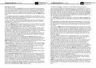
future-l, -xl, -xxl - Schulze Elektronik GmbH
future-l, -xl, -xxl - Schulze Elektronik GmbH
future-l, -xl, -xxl - Schulze Elektronik GmbH

Create successful ePaper yourself
Turn your PDF publications into a flip-book with our unique Google optimized e-Paper software.
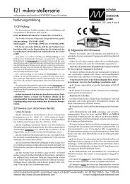
<strong>future</strong>-l, <strong>xl</strong>, x<strong>xl</strong><br />
Power speed controller for brushless and sensorless motors<br />
Operating instructions V 1 Date of issue: 23 JUN 2011<br />
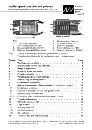
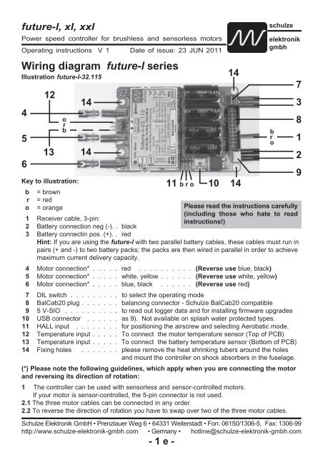
Wiring diagram <strong>future</strong>-l series<br />
Illustration <strong>future</strong>-l-32.115<br />
4<br />
5<br />
6<br />
12<br />
13<br />
o r<br />
b<br />
Key to illustration:<br />
b = brown<br />
r = red<br />
o = orange<br />
14<br />
14<br />
1 Receiver cable, 3-pin:<br />
2 Battery connection neg (-). . black<br />
3 Battery connectin pos. (+). . red<br />
- 1 e -<br />
11 b r o<br />
schulze<br />
elektronik<br />
gmbh<br />
Please read the instructions carefully<br />
(including those who hate to read<br />
instructions!)<br />
Hint: If you are using the <strong>future</strong>-l with two parallel battery cables, these cables must run in<br />
pairs (+ and -) to two battery packs; the packs are then wired in parallel in order to achieve<br />
maximum current delivery capacity.<br />
4 Motor connection* . . . . . red . . . . . . . . . . (Reverse use blue, black)<br />
5 Motor connection* . . . . . white, yellow . . . . . . (Reverse use white, yellow)<br />
6 Motor connection* . . . . . blue, black . . . . . . (Reverse use red)<br />
7 DIL switch . . . . . . . . . to select the operating mode<br />
8 BalCab20 plug . . . . . . . balancing connector - <strong>Schulze</strong> BalCab20 compatible<br />
9 5 V-SIO . . . . . . . . . . to read out logger data and for installing firmware upgrades<br />
10 USB connector . . . . . . as 9). Not available on splash water protected types.<br />
11 HALL input . . . . . . . . for positioning the airscrew and selecting Aerobatic mode.<br />
12 Temperature input . . . . . To connect the motor temperature sensor (Top of PCB)<br />
13 Temperature input . . . . . To connect the battery temperature sensor (Bottom of PCB)<br />
14 Fixing holes . . . . . . . please remove the heat shrinking tubers around the holes<br />
and mount the controller on shock absorbers in the fuselage.<br />
(*) Please note the following guidelines, which apply when you are connecting the motor<br />
and reversing its direction of rotation:<br />
1 The controller can be used with sensorless and sensor-controlled motors.<br />
If your motor is sensor-controlled, the 5-pin connector is not used.<br />
2.1 The three motor cables can be connected in any order.<br />
2.2 To reverse the direction of rotation you have to swap over two of the three motor cables.<br />
<strong>Schulze</strong> <strong>Elektronik</strong> <strong>GmbH</strong> • Prenzlauer Weg 6 • 64331 Weiterstadt • Fon: 06150/1306-5, Fax: 1306-99<br />
http://www.schulze-elektronik-gmbh.com • Germany • hotline@schulze-elektronik-gmbh.com<br />
10<br />
14<br />
14<br />
b<br />
r<br />
o<br />
7<br />
3<br />
8<br />
1<br />
2<br />
9
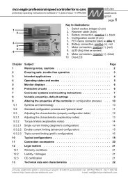
<strong>future</strong>-l, <strong>xl</strong>, x<strong>xl</strong><br />
Power speed controller for brushless and sensorless motors<br />
Operating instructions V 1 Date of issue: 23 JUN 2011<br />
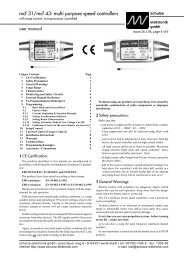
Wiring diagram <strong>future</strong>-<strong>xl</strong> series<br />
Illustration <strong>future</strong>-<strong>xl</strong>-32.200 / 32.202 / 40.160 / 40.161 (WK)<br />
4<br />
5<br />
6<br />
12<br />
13<br />
o r<br />
b<br />
14<br />
14<br />
- 2 e -<br />
schulze<br />
elektronik<br />
gmbh<br />
11 b r o 10<br />
14<br />
Key to illustration:<br />
b = brown<br />
r<br />
o<br />
= red<br />
= orange<br />
Please read the instructions carefully<br />
(including those who hate to read<br />
1 Receiver cable, 3-pin:<br />
instructions!)<br />
2 Battery connection neg (-). . black<br />
3 Battery connectin pos. (+). . red<br />
Hint: If you are using the <strong>future</strong>-<strong>xl</strong> with two parallel battery cables, these cables must run<br />
in pairs (+ and -) to two battery packs; the packs are then wired in parallel in order to achieve<br />
maximum current delivery capacity.<br />
4 Motor connection* . . . . . red . . . . . . . . . . (Reverse use blue, black)<br />
5 Motor connection* . . . . . white, yellow . . . . . . (Reverse use white, yellow)<br />
6 Motor connection* . . . . . blue, black . . . . . . (Reverse use red)<br />
7 DIL switch . . . . . . . . . to select the operating mode<br />
8 BalCab20 plug . . . . . . . balancing connector - <strong>Schulze</strong> BalCab20 compatible<br />
9 5 V-SIO . . . . . . . . . . to read out logger data and for installing firmware upgrades<br />
10 USB connector . . . . . . as 9). Not available on splash water protected types.<br />
11 HALL input . . . . . . . . for positioning the airscrew and selecting Aerobatic mode.<br />
12 Temperature input . . . . . To connect the motor temperature sensor (Top of PCB)<br />
13 Temperature input . . . . . To connect the battery temperature sensor (Bottom of PCB)<br />
14 Fixing holes . . . . . . . please remove the heat shrinking tubers around the holes<br />
and mount the controller on shock absorbers in the fuselage.<br />
(*) Please note the following guidelines, which apply when you are connecting the motor<br />
and reversing its direction of rotation:<br />
1 The controller can be used with sensorless and sensor-controlled motors.<br />
If your motor is sensor-controlled, the 5-pin connector is not used.<br />
2.1 The three motor cables can be connected in any order.<br />
2.2 To reverse the direction of rotation you have to swap over two of the three motor cables.<br />
14<br />
b r<br />
o<br />
7<br />
3<br />
8<br />
1<br />
2<br />
9
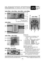
<strong>future</strong>-l, <strong>xl</strong>, x<strong>xl</strong><br />
Power speed controller for brushless and sensorless motors<br />
Operating instructions V 1 Date of issue: 23 JUN 2011<br />
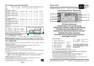
Wiring diagram <strong>future</strong>-x<strong>xl</strong> series<br />
Illustration <strong>future</strong>-x<strong>xl</strong>-40.300 / 40.303 K or WK<br />
4<br />
5<br />
6<br />
14<br />
Key to illustration:<br />
b = brown<br />
r = red<br />
o = orange<br />
8<br />
7<br />
14<br />
11 b r o<br />
1 Receiver cable, 3-pin:<br />
2 Battery connection neg (-). . black<br />
3 Battery connectin pos. (+). . red<br />
10<br />
- 3 e -<br />
schulze<br />
elektronik<br />
gmbh<br />
Please read the instructions carefully<br />
(including those who hate to read<br />
instructions!)<br />
Hint: If you are using the <strong>future</strong>-x<strong>xl</strong> with two parallel battery cables, these cables must run<br />
in pairs (+ and -) to two battery packs; the packs are then wired in parallel in order to achieve<br />
maximum current delivery capacity.<br />
4 Motor connection* . . . . . red . . . . . . . . . . (Reverse use blue, black)<br />
5 Motor connection* . . . . . white, yellow . . . . . . (Reverse use white, yellow)<br />
6 Motor connection* . . . . . blue, black . . . . . . (Reverse use red)<br />
7 DIL switch . . . . . . . . . to select the operating mode<br />
8 BalCab20 plug . . . . . . . balancing connector - <strong>Schulze</strong> BalCab20 compatible<br />
9 5 V-SIO . . . . . . . . . . to read out logger data and for installing firmware upgrades<br />
10 USB connector . . . . . . as 9). Also available on splash water protected types.<br />
11 HALL input + LED . . . . . for positioning the airscrew and selecting Aerobatic mode.<br />
12 Temperature input . . . . . To connect the motor temperature sensor<br />
13 Temperature input . . . . . To connect the battery temperature sensor<br />
14 Fixing holes . . . . . . . Mount the controller always on shock absorbers in the<br />
fuselage<br />
15 „aldis-HV“ output . . . . is activated at full throttle (mounted only if required)<br />
(*) Please note the following guidelines, which apply when you are connecting the motor<br />
and reversing its direction of rotation:<br />
1 The controller can be used with sensorless and sensor-controlled motors.<br />
If your motor is sensor-controlled, the 5-pin connector is not used.<br />
2.1 The three motor cables can be connected in any order.<br />
2.2 To reverse the direction of rotation you have to swap over two of the three motor cables.<br />
13<br />
9<br />
14<br />
14<br />
15<br />
12<br />
b r<br />
o<br />
2<br />
3<br />
1<br />
3<br />
2
Dear customer,<br />
Congratulations on your choice of a <strong>future</strong>-l, -<strong>xl</strong> or -x<strong>xl</strong> speed controller, which is a micro-computer<br />
controlled unit developed and manufactured entirely in Germany, designed for brushless and<br />
sensorless 3-phase rotary current motors.<br />
All models of the <strong>future</strong> are amongst the world’s most powerful speed controllers.<br />
<strong>future</strong> controllers have the most intelligent, comprehensive software, which means that this speed<br />
controller (or governor) is capable of operating virtually any brushless motor currently on the market<br />
with optimum efficiency.<br />
The ips (intelligent programming system for <strong>future</strong>-l, -<strong>xl</strong>, -x<strong>xl</strong>) makes it as simple as possible to<br />
configure the controller to match any radio control system and operating mode: The transmitter<br />
stick travel settings of the wing programs is fully automatical, the operating modes can easily be<br />
configured by the DIL switch.<br />
The integral motor connector system is a feature of all <strong>future</strong>-l, -<strong>xl</strong> or -x<strong>xl</strong> , and makes it possible<br />
to remove the unit for servicing, or for fitting in another model, simply by unplugging the cables<br />
- no soldering is required.<br />
Contents<br />
Chapter Subject Page<br />
- Wiring diagrams . . . . . . . . . . . . . . . . . . . . . 1<br />
1 Warning notes, cautions . . . . . . . . . . . . . . . . . 5<br />
2 Ensuring safe, trouble free operation . . . . . . . . . . . 6<br />
3 Types, intended applications and common highlights . . . 7<br />
4 Protective circuits . . . . . . . . . . . . . . . . . . . . 8<br />
5 Monitor displays . . . . . . . . . . . . . . . . . . . . . 9<br />
6 Installing and connecting the unit . . . . . . . . . . . . 10<br />
7 Connector systems and mounting instructions . . . . . . 12<br />
8 Using the controller for the first time . . . . . . . . . . . 13-21<br />
8.1 ips - the intelligent programming system . . . . . . . . . . . 13<br />
8.2 Symbols and terminology . . . . . . . . . . . . . . . . . . 14<br />
8.3.1 Mode setting for Wing aircraft models . . . . . . . . . . . . 15<br />
8.3.2 Mode setting for Aerobatic wing models . . . . . . . . . . . 16<br />
8.3.3 Mode setting for Helicopter models and important tips . . . . 17<br />
8.3.4 Mode setting for Car models . . . . . . . . . . . . . . . . 20<br />
8.3.5 Mode setting for Boat models . . . . . . . . . . . . . . . . 21<br />
9 Tips . . . . . . . . . . . . . . . . . . . . . . . . . . . 22<br />
10 Interfaces . . . . . . . . . . . . . . . . . . . . . . . . 23<br />
11 Interface protocols . . . . . . . . . . . . . . . . . . . . 24<br />
12 Accessories . . . . . . . . . . . . . . . . . . . . . . . . 25<br />
13 Additional features of the <strong>future</strong>-x<strong>xl</strong> . . . . . . . . . . . . 26<br />
14 Legal matters . . . . . . . . . . . . . . . . . . . . . . . 27<br />
15 Specifications . . . . . . . . . . . . . . . . . . . . . . 28<br />
16 Product overview . . . . . . . . . . . . . . . . . . . . 28<br />
- 4 e -
1 Warning notes, cautions<br />
Electric motors fitted with propellers are<br />
dangerous and require proper care for safe<br />
operation. Keep well clear of the propeller at<br />
all times when the battery pack is connected.<br />
Technical defects of an electrical or mechanical<br />
nature may result in unintended motor<br />
runs; loose parts may cause serious personal<br />
injuriy and/or property damage.<br />
The CE-certificate on the speed controller<br />
does not absolve you from taking proper care<br />
when handling the system!<br />
Speed controllers are exclusively for use in<br />
RC models. Their use in man-carrying aircraft<br />
is prohibited.<br />
Speed controllers are not protected against<br />
reverse polarity (+ terminal and - terminal<br />
reversed). Connecting the battery pack to<br />
the motor leads of the controller will almost<br />
certainly cause irreparable damage.<br />
Electronic equipment is sensitive to humidity.<br />
Speed controllers which have got wet may<br />
not function properly even after thorough<br />
drying. You should send them back to us for<br />
cleaning and testing.<br />
Do not use speed controllers in conjunction<br />
with a power supply connected to the mains.<br />
Energy reversal can occur when the motor<br />
slows down and stops, and this may damage<br />
the power supply or cause an over-voltage<br />
condition which could damage the controller.<br />
Never disconnect the flight pack while the<br />
motor is running, as this could cause damage<br />
on a speed controller.<br />
Please take care when switching off the<br />
receiver battery: depending on the receiver<br />
you are using, it may send an incorrect throttle<br />
signal to the <strong>future</strong> at this moment, which<br />
could then cause the motor to burst into life<br />
unexpectedly.<br />
Protect the speed controller from mechanical<br />
loads, vibration, dirt and contamination.<br />
Keep the cables to the motor as short as<br />
possible (max. length = 10 cm / 4”).<br />
- 5 e -<br />
Do not exceed the maximum stated length of<br />
cable between battery and <strong>future</strong> (max.<br />
length: see chapter 6.3.1). The wiring inside<br />
the battery pack must also be as short as<br />
possible. Use in-line soldered “stick” packs.<br />
For the same reason, use a clamp-type<br />
amperemeter, not a series meter with shunt<br />
resistor.<br />
Never leave the flight battery connected<br />
when ...<br />
... the model is not in use and/or<br />
... the battery pack is being charged.<br />
Although some speed controllers feature a<br />
separate On/Off switch, this does not isolate<br />
it completely from the battery.<br />
Speed controllers can only function properly<br />
if they are in full working condition. The protective<br />
and monitoring circuits can also only<br />
work if the speed controller is in good operating<br />
condition.<br />
In the case of motor failure (e.g.short circuits<br />
in the windings) the over-temperature sensor<br />
in the controllers may react too slowly to<br />
prevent damage. Switch the motor off immediately<br />
to prevent permanent damage to the<br />
speed controller.<br />
Note: Please remember that the monitoring<br />
circuits are unable to detect every abnormal<br />
operating condition, such as a short between<br />
the motor cables. Note also that a stalled<br />
motor will only trip the current limiter if the<br />
motor's stall current is well above the controller's<br />
peak current. For example, if you are<br />
using an 80 A controller in conjunction with a<br />
20 A motor, the current monitor will not detect<br />
an excessive current even when the motor is<br />
stalled.<br />
Common information<br />
If you are using a <strong>future</strong> with BEC system<br />
then connect on no account a separate receiver<br />
battery or an electronic battery switch<br />
(two receiver batteries), as this may cause<br />
damage to the speed controller and could<br />
cause current to flow from the receiver battery<br />
to the motor.
2 Ensuring safe, trouble-free operation<br />
Use only compatible connectors. A 2 mm pin<br />
cannot provide reliable contact in a 2.5 mm<br />
socket. The same applies with 2mm goldcontact<br />
pins and 2 mm tin-plated sockets.<br />
Please also remember that ...<br />
... the wiring of your RC-components must be<br />
checked regularly for loose wires, oxidation,<br />
or damaged insulation.<br />
... your receiver and the aerial must be at<br />
least 3 cm (>1") away from motor, speed<br />
controller and high-current cables. For example,<br />
the magnetic fields around the highcurrent<br />
cables can cause interference to the<br />
receiver.<br />
... all high-current cables must be as short as<br />
possible. Maximum length between flight<br />
pack and speed controller must never exceed<br />
the length listed in chapter 6.3.1; the length<br />
between speed controller and motor should<br />
not exceed 10 cm (4") to avoid interferences.<br />
... all high-current cables longer than 5 cm<br />
(2") must be twisted together. This applies in<br />
particular to the motor power cables, which<br />
are very powerful sources of radiated interference.<br />
... in model aircraft: half of the receiver aerial's<br />
length should be routed along the fuselage,<br />
the other half should be allowed to trail<br />
freely (take care not to tread on it). Do not<br />
attach the end of the aerial to the fin!<br />
... in model boats: half of the receiver aerial's<br />
length should be deployed inside the hull<br />
above the waterline, the other half should be<br />
threaded into a small tube mounted upright.<br />
Every time you intend to use the power<br />
system - before you turn on the receiver -<br />
make sure that ...<br />
... no one else is using the same frequency<br />
(identical channel number).<br />
... your transmitter is switched on and the<br />
throttle stick is (as a rule) in the STOP position<br />
(exceptions see Section 9).<br />
- 6 e -<br />
Carry out a range check before each flight.<br />
Ask an assistand to hold the model aircraft<br />
and set the throttle stick to the half throttle<br />
position. Collapse the transmitter aerial. Walk<br />
away from the model to the distance stated<br />
by the RC system manufacturer (this might<br />
be a distance of about 50-60 m = 200'). Make<br />
sure that you still have full control of the<br />
system at this range.<br />
As a general rule: receiver interference is<br />
more likely to occur when using a controller<br />
with BEC system, as these units do not feature<br />
an opto-coupler with its optical link.<br />
When Ni-Cd batteries approach the end of<br />
their charge, voltage falls drastically and<br />
quickly. The <strong>future</strong> detects this and reduces<br />
power to the motor automatically. This should<br />
leave sufficient energy to bring your model<br />
safely back home. However, if you use a<br />
small number of cells of high internal resistance<br />
and operate at high motor currents, the<br />
controller may reduce power before the pack<br />
is discharged. You can eliminate this problem<br />
by using low resistance straps to connect the<br />
cells, or use the direct cell-to-cell soldering<br />
technique (“sticks”) and short, heavy-gauge<br />
wire if you assemble your own batteries.<br />
Your receiver also benefits from the stability<br />
of the voltage supplied from the battery by a<br />
BEC system. If the BEC voltage is stable, the<br />
receiver is less liable to suffer interference.<br />
The CE symbol is your guarantee that the<br />
unit meets all the relevant interference emission<br />
and rejection regulations when it is in<br />
use.<br />
If you encounter problems operating the<br />
<strong>future</strong> controller, please note that many<br />
problems are due to an unsuitable combination<br />
of receiving system components, or an<br />
inadequate installation in the model.
3 Types, intended applications and common highlights<br />
Common Highlights<br />
Almost all of this <strong>future</strong>-l, -<strong>xl</strong>, -x<strong>xl</strong> controllers are<br />
universal types which can be used in model<br />
aircraft, helicopters, boats and cars. They<br />
includes an opto-coupler which ensures minimum<br />
possible transfer of interference to your receiver.<br />
Warning: A by-passed opto-coupler by an external<br />
BEC can lead to interference problems.<br />
The <strong>future</strong>-l and -<strong>xl</strong> controllers are designed with<br />
a relatively big PCB with a lot of copper on the<br />
inner layers. It is used as a cooling plate which<br />
distributes and dissipates the heat which especially<br />
rises in part throttle use.<br />
„K“-Types:<br />
All <strong>future</strong>-l and -<strong>xl</strong> controllers with a single ”K” in<br />
the type designation feature a finned heat-sink.<br />
This unit is an excellent choice for use under partload<br />
conditions, i.e. operating them primarily at<br />
part-throttle settings does not lead so quickly to<br />
overheating, even with high cell counts.<br />
„WK“-Types:<br />
These types are protected by a dipping varnish.<br />
Depending on the type they are equipped with<br />
one (-l) or two water cooling tubes (-<strong>xl</strong>). The -x<strong>xl</strong><br />
is equipped with an aluminium cooling block with<br />
a sequence of internal tightly contiguous cooling<br />
windings.<br />
• „Auto-arm“ function and „power on reset“.<br />
• Up to 2048-step resolution over the whole<br />
control range for extremely fine speed control.<br />
• RC-Car programm with proportional brake.<br />
• RC-Car- and boat-programm with reverse gear<br />
(can be additionally switched on).<br />
• „ips“ (intelligent programming system) with no<br />
pots! The speed controller uses - depending on<br />
the operating mode - fixed throttle positions or<br />
automatically configures itself every time to the<br />
stick travel when you go airborn.<br />
• During the “Power-On” process the motor acts<br />
as a loudspeaker to give you audible confirmation<br />
of the procedure.<br />
• Connectors (sensors not included):<br />
2 temperature sensors, HALL-sensor, 5V-SIO,<br />
USB (not at „W“-types).<br />
<strong>Schulze</strong> BalCab20 balancing cable connector to<br />
monitor the single cells in a lithium battery pack.<br />
When this connector is not connected then the<br />
throttle is decreased when the pack voltage<br />
reaches about 59 % or 66 % of the connecting<br />
voltage at all battery types.<br />
- 7 e -<br />
Types overview<br />
<strong>future</strong>-l<br />
<strong>future</strong>-l-24.150WK<br />
For 10-24 Nickel- or 3-8 Lithium-cells.<br />
150 A full throttle for 3 Ah, 200 A for 10 sec.<br />
By the cooling water connection and the additional<br />
splash-water protection the speed controller<br />
is particularly applicable in boats and cars.<br />
<strong>future</strong>-l-32.115<br />
For 10-32 Nickel- or 3-10 Lithium-cells.<br />
115 A full throttle for 3 Ah, 150 A for 10 sec.<br />
<strong>future</strong>-l-32.115WK<br />
As above. By the cooling water connection and<br />
additional splash-water protection the controller<br />
is particularly applicable in boats and cars.<br />
<strong>future</strong>-l-40.100<br />
For 10-40 Nickel- or 3-14 Lithium- cells.<br />
100 A full throttle for 3 Ah, 133 A for 10 sec.<br />
<strong>future</strong>-l-40.100WK<br />
As above. By the cooling water connection and<br />
additional splash-water protection the controller<br />
is particularly applicable in boats and cars.<br />
<strong>future</strong>-<strong>xl</strong><br />
WK-Types: By the cooling water connection<br />
and the splash-water protection the speed<br />
controller is particularly applicable in boats<br />
and cars.<br />
<strong>future</strong>-<strong>xl</strong>-32.200WK / 32.202WK<br />
For 10-32 Nickel- or 3-10 Lithium- cells.<br />
200 A full throttle for 3 Ah, 260 A for 10 sec.<br />
<strong>future</strong>-<strong>xl</strong>-40.160 / 40.161 (WK)<br />
For 20-40 Nickel- or 4-14 Lithium- cells.<br />
160 A full throttle for 3 Ah, 210 A for 10 sec.<br />
<strong>future</strong>-x<strong>xl</strong><br />
<strong>future</strong>-x<strong>xl</strong>-40.300K / 40.303K or WK<br />
For 12-40 Nickel- or 4-14 Lithium- cells.<br />
330 A full throttle for 3 Ah, 440 A for 10 sec.<br />
<strong>future</strong>-x<strong>xl</strong>-40.300WK / 40.303WK<br />
By the cooling water connection and the<br />
splash-water protection the speed controller<br />
is particularly applicable in boats and cars.
4 Protective circuits<br />
Note: the monitor circuits are effective, but they<br />
cannot detect every possible operating condition.<br />
4.1 Temperature monitors<br />
4.1.1 The temperature monitor for the power<br />
MOSFETs and the PCB throttles down the motor<br />
and later switches off the motor. You can reset<br />
the unit using the "auto-arm" function (throttle<br />
stick to stop for about 2 sec.)<br />
If the motor windings are short-circuited the<br />
temperature monitor reacts too slowly to prevent<br />
damage. Switch the motor off immediately to<br />
avoid permanent damage to the speed controller.<br />
4.1.2 The temperature monitor, operating via the<br />
external sensors, throttles the motor back to 50%<br />
of power (helicopter: to 90% of the set nominal<br />
rotational speed) in order to warn the user that<br />
the temperature is excessive. The default limits<br />
are 100°C for motor temperature, and 70°C for<br />
battery temperature.<br />
4.2 Voltage monitor<br />
As soon as the voltage of the drive battery falls<br />
back to the under voltage threshold the motor is<br />
throttled back (more information about the threshold<br />
value see chapter 8.9).<br />
If the situation which caused the controller to<br />
throttle back continues for more than a short time,<br />
the unit switches the motor off.<br />
Of course, you can re-start the motor again briefly<br />
by moving the throttle stick back to "stop" for<br />
about 2 seconds to re-arm the system.<br />
In this situation you retain full control of the model<br />
until the receiver battery is flat.<br />
4.3 Current Monitor<br />
The <strong>future</strong> controllers feature a current monitor<br />
circuit which trips when the current rises above<br />
the specified maximum value. If the motor is<br />
stalled, the motor is throttled back. This means,<br />
that a motor which draws an excessive current<br />
will never reach full-throttle, and the current may<br />
stay below the specified maximum value. If <strong>future</strong><br />
is a short time in current limiting mode, it will<br />
disarm itself (switching off the motor). Re-arming<br />
= apply 2 seconds “stopp”.<br />
- 8 e -<br />
4.4 Maximum rotational speed<br />
monitor<br />
If maximum rotational speed of the motor will<br />
exceed, <strong>future</strong> throttles down. In this state do not<br />
use longer than 1 second. After 2 seconds at<br />
maximum speed the motor is switched off.<br />
Because of this: Do not run motor without airscrew.<br />
4.5 Minimum rotational speed<br />
monitor<br />
To ensure that the controller detects the rotor<br />
position reliably, this series of <strong>future</strong> types sets a<br />
defined minimum rotational speed.<br />
This protective function can cause the motor to be<br />
reluctant to start up or even to a refused start if its<br />
torque limit is exceeded.<br />
If this should happen, check also under full throttle<br />
that the maximum permissible motor current is<br />
not exceeded. In this case a more leightweight<br />
propeller and/or one step smaller in diameter<br />
must be used.<br />
4.6 Operation with only two motor<br />
phases connected<br />
If you attempt to operate a motor with only two<br />
phases connected, the controller detects after a<br />
brief period that the motor is unable to follow.<br />
Nothing happens, and no connection melody is<br />
emitted.<br />
If one motor connector comes adrift in use, the<br />
<strong>future</strong> disarms itself within milliseconds.<br />
4.7 Reverse polarity protection<br />
These speed controllers are not protected against<br />
reversed polarity!<br />
4.8 Receiver signal monitor<br />
If the receiver signal fails, or the signal is longer<br />
or shorter than the usual range of values, the<br />
smart controller reverts to hold mode for about<br />
300 milliseconds (helicopter = 1.5 s) before<br />
switching to disarmed mode.<br />
This warning function enables you to eliminate<br />
receiver interference before you actually lose your<br />
model, perhaps by modifying the installation or<br />
changing the radio control components<br />
4.9 Watchdog<br />
If this circuit is tripped the speed controller stops<br />
working briefly and then reverts to normal operation.
4.10 Beep-Codes<br />
Under certain circumstances <strong>future</strong> controllers<br />
refuses to work after connection to the power<br />
battery and beeps - if possible - an error code:<br />
4 beeps:<br />
battery weak (empty or high impedance) or<br />
battery cables too long. (Remedy e.g. by<br />
adding low ESR electrolytic capacitors with<br />
fitting tension and capacity near the <strong>future</strong> -<br />
see picture below)<br />
5 beeps:<br />
motor too strong or short circuit in the windings.<br />
6 beeps:<br />
double tone beep, normal beep, double tone...<br />
(motor defective, battery weak, <strong>future</strong> defective)<br />
Remedy when the <strong>future</strong> beeps 4 times<br />
How to mount additional blocking capacitors:<br />
The electrolytic capacitors should be from the<br />
same type, same capacity and also the same<br />
tension as equipped on the <strong>future</strong>.<br />
Glue capacitors together as shown in the<br />
picture, bend legs to the right (to the left),<br />
solder them together. Add a reinforce lead to<br />
the neg. and to the pos. pole each.<br />
Strip the isolation in a distance of about 5 cm<br />
from the controller on a length of 5 mm and<br />
tin the core. Wind overhanging leads around<br />
the battery leads and solder them tight.<br />
Fix leads with tape and/or heat shrinking tube.<br />
Hint: By means of the additional capacitors<br />
the anti-spark circuit is inoperative.<br />
- 9 e -<br />
5 Monitor displays<br />
5.1 The <strong>future</strong> is not fitted with LED to indicate<br />
its operating state.<br />
5.2 However, when the unit is being configured<br />
the set stick end-points are confirmed<br />
by a beep from the motor or a barely reciptible<br />
"blip" in full-throttle position when<br />
normal using with activated brake. (See also<br />
the corresponding section 4.10 or 8).<br />
5.3 aldis connection (alarm display)<br />
When printing the manual only available<br />
on the <strong>future</strong>-x<strong>xl</strong>.<br />
THE useful aid to optimising the power system,<br />
also “flat battery” warning and high temperature<br />
indicator This is a panoramic LED<br />
array consisting of red LEDs, usable with<br />
10...32* / 40** Ni-cells or 3...10* / 14** Li-cells,<br />
designed to be mounted on the underside of<br />
the helicopter in any clearly visible position.<br />
We can retro-fit the connection provided that<br />
the circuit board is suitable (or you can do it,<br />
but no guarantee claims; take care: the flight<br />
battery voltage is present at this connection).<br />
This connection always becomes active if …<br />
5.3.1 ... the motor reaches full-throttle (in “governor”<br />
mode this means: I cannot maintain<br />
the rotational speed, i.e.: motor + gearbox +<br />
collective pitch angle = incorrectly matched;<br />
or: battery flat, land immediately) and<br />
5.3.2 ... the <strong>future</strong> detects overheating<br />
(aldis comes on at around 90°C and goes<br />
out again at around 80°C).<br />
(*) Previous aldis: max. 42 volts<br />
(**) New: aldis-HV: max. 60 volts
6 Installations, connections<br />
6.1 Receiver connection<br />
Connect the (3-wire) receiver cable<br />
attached to the <strong>future</strong> to the receiver<br />
servo output corresponding to the<br />
throttle stick on the transmitter (or a<br />
switch if that is your preference).<br />
The <strong>future</strong> receives its control signal<br />
via this receiver socket.<br />
Hint: Because of the fact that the <strong>future</strong><br />
is not equipped with a BEC system<br />
and the control pulses from the<br />
receiver is led through an electrically<br />
insulating opto-coupler to the <strong>future</strong><br />
your receiver and the servos are in<br />
need of a receiver battery to work as<br />
expected.<br />
6.2 Installing in the fuselage<br />
Velcro (hoop and loop) tape is the<br />
ideal method of mounting the <strong>future</strong>-l<br />
oder -<strong>xl</strong> controllers in the fuselage. Of<br />
course they also can be mounted on<br />
shock absorbers.<br />
The -x<strong>xl</strong> should be mounted exclusively<br />
on shock absorbers in the fuselage.<br />
It is essential to use shock absorbers<br />
of adequate length (height), otherwise<br />
the circuit board may suffer mechanical<br />
damage, and this may then result<br />
in electrical damage.<br />
Do not pack the <strong>future</strong> in foam as this<br />
may lead to a heat buildt-up in the<br />
controller.<br />
- 10 e -<br />
6.3 Connecting the battery<br />
6.3.1 Cable length battery <strong>future</strong><br />
Do not exceed the maximum stated<br />
length of cable between battery and<br />
<strong>future</strong>, otherwise the speed controller<br />
may be damaged.<br />
This rule still applies even if your power<br />
system features a retractable (folding)<br />
motor, or your model necessarily<br />
includes a long battery cable!!! Especially<br />
most of the lithium battery packs<br />
with odd cell count or round cells<br />
which are assembled in a zig-zag pattern<br />
also produce ”long cable” effects.<br />
Use in-line (end-to-end) soldered<br />
packs exclusively.<br />
The maximum cable lengths inside the<br />
battery pack plus the length between<br />
the battery pack and the PCB of the<br />
<strong>future</strong> are as follows:<br />
fut-l: (14“) 35 cm red, 35 cm black<br />
fut-<strong>xl</strong>: (10“) 25 cm red, 25 cm black<br />
fut-x<strong>xl</strong>: (14“) 35 cm red, 35 cm black<br />
6.3.2 Selecting appropriate connectors<br />
/ wiring battery packs in parallel<br />
It is essential to select connectors<br />
whose maximum load capacity is appropriate<br />
to the motor's current drain<br />
and the battery's maximum discharge<br />
rate.<br />
For this reason virtually all <strong>future</strong>-l, -<strong>xl</strong><br />
and -x<strong>xl</strong> types are fitted with two pairs<br />
of battery cables.<br />
The <strong>future</strong>-l-40.100(WK) is the sole<br />
type which is connected adequately<br />
using only single 6 mm connectors and<br />
a battery capable of delivering up to<br />
100 A.
If higher currents are used, the battery<br />
packs must be wired in parallel.<br />
When using the <strong>future</strong>-l or -<strong>xl</strong> the<br />
easiest method of accomplishing this<br />
is to fit each pair of cables with a pair<br />
of 4 mm polarised connectors. Take<br />
care to maintain correct polarity (Chapter<br />
7).<br />
If you are using the <strong>future</strong>-x<strong>xl</strong> types<br />
this procedure is not sufficient due to<br />
the maximum discharge rates of standard<br />
commercial battery packs. For<br />
this reason more than two packs<br />
should be wired in parallel, and these<br />
should be connected using 6 mm polarised<br />
connectors.<br />
Connectors which do not have a polarised<br />
insulator can be made safe (i.e.<br />
polarised) by soldering the <strong>future</strong>’s<br />
positive battery wire to a socket, and<br />
the <strong>future</strong>’s negative wire to a plug.<br />
We recommend that you choose your<br />
connectors using the right power rating<br />
from our selection in Section 7 - fitting<br />
any other type of connector invalidates<br />
the warranty.<br />
6.3.3 Connecting the balancer cable<br />
If you are using a battery with a <strong>Schulze</strong><br />
BalCab20 socket, all you need to<br />
complete the connection is a Bal-<br />
Cab20-Verl.<br />
If two packs of this type are wired in<br />
parallel, then the pack with the weakest<br />
cell (assuming that you know<br />
which this is) should be connected to<br />
the balancer socket of the <strong>future</strong>.<br />
Otherwise you also need a LiPoDiMA-<br />
TIC-SE14.<br />
If your battery is fitted with a different<br />
balancer connector, you can use our<br />
BalCab20-Set, fit an adapter or use<br />
LiPoDiMATICs with the appropriate<br />
connectors.<br />
- 11 e -<br />
The connection of the BalCab20 socket<br />
(balancing connector of the battery)<br />
must be connected before power<br />
cables of the <strong>future</strong> are connected to<br />
the battery. Only in this chronological<br />
order the single cell monitoring is active.<br />
Firmwareversion V 3.20 or higher<br />
allows the activation of the single cells<br />
monitoring a little bit later: when you<br />
apply throttle for the first time.<br />
6.4 Connecting the motor<br />
The cables to the motor should be<br />
kept as short as possible to avoid interferences<br />
to your reiceiver. Long<br />
cables tend to act as aerials and radiate<br />
interference; they also add unnecessary<br />
weight (see also section 2).<br />
Long cables should be twisted. Carry<br />
out the range check with the motor<br />
running at half-throttle. Check motor<br />
temperature during this test! Some<br />
motors grow hotter at long duration<br />
half throttle than at full throttle.<br />
Cut down the existing motor cables to a<br />
length of no more than 10 cm. Do not<br />
extend the motor cables except in exceptional<br />
cases; although this generally<br />
does not harm to the <strong>future</strong> itself.<br />
Under no account is it allowed to<br />
wind ferrite cores on the motor wires!<br />
Locate the cables with the pp60 plugs<br />
supplied with the controller (plugged<br />
into the integrated motor sockets of<br />
the <strong>future</strong>), and solder them to the<br />
motor cables. Observe solder instructions<br />
in section 7.2. See cover sheets<br />
(page 1-3) for details of cable configuration.<br />
Avoid pulling on the motor cables; we<br />
recommend that you secure the three<br />
motor plugs with glass-reinforced or<br />
fabric tape to prevent them being<br />
pulled out.
7 Connector systems and mounting instructions<br />
7.1 CT4, 4 mm gold-contact connector system; rating up to 80 A<br />
+ red sleeve wide plug socket sleeve narrow red ( akku)<br />
battery <strong>future</strong><br />
- black sleeve narrow socket plug sleeve wide black ( akku)<br />
Fit the connectors in the order shown above; the contacts are pressed in as follows:<br />
a. Rest plastic sleeve on vice jaws with cables hanging down.<br />
b. Close vice jaws until cables are just free to move.<br />
c. Fit plug into socket and tap into sleeve until latch engages.<br />
d. Fit socket onto plug and tap into sleeve until latch engages.<br />
7.2 pp60L, 6.0 mm gold contact system; rating up to about 150 A<br />
+ red red heat shrinking tube plug + spring socket + red ( akku)<br />
battery <strong>future</strong><br />
- black black heat shrinking tube socket plug - black ( akku)<br />
Fit the connectors in the order shown above:<br />
a. Strip the isolation from the leads, twist wires, tin them.<br />
b. Remove contact spring carefully with a pair of tweezers from the core of the<br />
plug to avoid over heating them.<br />
c. Solder plugs and sockets to the leads. Observe polarity (i.e. the colours of the<br />
leads) and the contact type (i.e. if male or female).<br />
d. Shrink heat shrinking tube segments as shown in the right part of the picture.<br />
e. Mount the contact spring again on its place.<br />
- 12 e -
8 Initial use<br />
8.1 ips, the intelligent programming system<br />
for configuring the <strong>future</strong>-l, -<strong>xl</strong>, -x<strong>xl</strong> to suit your application<br />
8.1.1 If you have a transmitter with adjustable servo travel we recommend that you set throttleservo<br />
to normal full travel, i.e. +/- 100%. Adjust Multiplex servo center pulse width to 1.5 ms<br />
(= -22% center or use uni-mode).<br />
8.1.2 The DIL switch bank of the ips allows to config the controller to various applications.<br />
It is not necessary to use any other aids (PC, programming PCB).<br />
8.1.2.1+2 The DIL-switches 1 and 2 are used to select the operating mode.<br />
Extensive information and explanations can be found on the following pages.<br />
8.1.2.3 Activating the brake, the governor mode or the reverse gear*<br />
8.1.2.4 Smooth start time or the range of the governor RPM regulation*<br />
8.1.2.5 Automatic adjustment to the mechanical transmitter stick travel or the use of the<br />
fixed given stick pulse width für e.g. neutral, full brake, full reverse and/or full throttle*<br />
8.1.2.6 Selection of the under voltage limit of the pack or cell tension<br />
(*) depending on the selected operating mode.<br />
Explanations re 8.1.2.5 - DIL-switch No. 5 = OFF<br />
The stick travel setup process is based on the previous standard procedure when the unit<br />
is first switched on, and is fully automatic:<br />
8.1.2.5.1 Under normal circumstances you simply proceed as previously: 1. Transmitter to<br />
stop, 2. Switch on receiver, 3. Connect flight pack / drive battery (<strong>future</strong> confirms this with<br />
”Power-On” tones = flight pack / drive battery connected), then learns the Stop position and<br />
confirms this with a beep; it is then armed, 4. Hold model in launch / start position, 5. Apply<br />
full-throttle (<strong>future</strong> learns full-throttle point, confirms with brief drop in rotational speed), 6.<br />
Launch / Start model. The process configures both the brake point and the full-throttle point,<br />
so full stick travel is always available when you operate the motor, giving ultra-fine control.<br />
8.1.2.5.2 If you find the brief motor speed drop at the full-throttle setting disturbing (confirmation<br />
of learned full throttle position), or don’t wish to apply full throttle at launch / start,<br />
there is an alternative method: set the transmitter stick to the full-throttle position before you<br />
switch on the receiving system and connect the flight pack / drive battery. After the ”Power-<br />
On” tones the <strong>future</strong> emits two beeps (to confirm it has learned the full throttle position); the<br />
transmitter stick is then moved to Stop, and the <strong>future</strong> emits one beep (to confirm it has<br />
learned the brake position); the controller is now armed, and the model can be launched or<br />
started at any throttle position.<br />
8.1.2.5.3 In the model car and boat programs the controller only learns the neutral point; the<br />
full-throttle position is a fixed margin from the learned neutral point.<br />
8.1.2.5.4 In the helicopter programs the stick travels cannot be configured by the user.<br />
The neutral and full brake and full-throttle settings are fixed.<br />
Explanations re 8.1.2.5 - DIL-switch No. 5 = ON (e.g.: stop = 1,1 ms, full throttle = 1,9 ms)<br />
The full brake-, neutral- and full throttle positions are fixed.<br />
In all operating modes the controllers work as described in chapter 8.1.2.5.4.<br />
When you want to exploit the full travel of the transmitter stick to vary motor speed, it could<br />
be possible that you program a slight reduction in servo travel at the transmitter.<br />
Caution: If you reduce servo travel too far, full throttle will not be available, and the controller<br />
will not reach the Stop setting, and therefore will not reach the armed state!<br />
8.1.3 If your <strong>future</strong> beeps twice (double beep = full throttle position) when the transmitter stick is<br />
at the brake position, you must reverse the throttle channel using your transmitter’s servo<br />
reverse function. If you neglect to do this, the <strong>future</strong> will be armed (single beep) at the transmitter’s<br />
full-throttle setting, and run at full-throttle at the stop setting, which is not recommended!<br />
- 13 e -
8.2 Symbols and terminology<br />
Stick: The throttle stick on the transmitter<br />
Neutral position (self neutralising stick, 1.36 ... 1.67 ms pulse width)<br />
Idle position (position where the motor just barely runs) or stop position (brake).<br />
Brake position or idle position: (equivalent to e.g. 1.1 ms pulse width)<br />
Position of the throttle stick where the motor stops or just barely runs.<br />
Full-throttle position: (equivalent to e.g. 1.9 ms pulse width)<br />
100% voltage passed to the motor.<br />
Wait (e.g. 1 second)<br />
Audible indicators:<br />
These indicators are only audible when a motor is attached, as the motor itself acts<br />
as the loudspeaker.<br />
Power-On melody (Flight-/drive battery connected)<br />
Single beep (Brake position detected/learned, <strong>future</strong> is armed)<br />
Double beep (Full throttle position detected/learned, <strong>future</strong> not armed)<br />
Momentary interruption in running (full throttle position learned while running)<br />
c.v. = connecting voltage<br />
The controller measures and stores the battery voltage when the battery pack is connected<br />
to the controller. This value is stored unchanged until the pack is separated from the battery.<br />
- 14 e -<br />
�����<br />
�<br />
��<br />
���
8.3.1 Mode setting wing aircraft models<br />
DIL switch # 1 = 0 = air<br />
DIL switch # 2 = 0 = wing<br />
DIL switch # 3 = 0 = brake off<br />
1 = brake enabled<br />
DIL switch # 4 = 0 = short soft start for direct drive + planetary gear<br />
1 = smoother soft start for belt drive gearbox<br />
DIL switch # 5 = 0 = learns throttle stick travel automatically<br />
1 = uses fixed stick positions (1,1 ms - 1,9 ms)<br />
DIL switch # 6 = 0 = LiPo empty level 3.0 V / cell or 59 % of c.v.<br />
1 = LiPo empty level 3.3 V / cell or 66 % of c.v.<br />
a Receiver off (flight battery disconnected)<br />
b Set throttle stick to brake position<br />
c Switch transmitter on<br />
d Switch receiver on and connect flight battery<br />
e <strong>future</strong> confirms by playing the „Power-On“ tune...<br />
f ...waits about 1 second, confirms brake position with a<br />
single beep and is armed!<br />
g Hold model in launch position, keep clear of danger area<br />
around propeller!<br />
h* Move throttle quickly to full-throttle position and ...<br />
... leave it there for about 1 second (motor is running!)<br />
i* <strong>future</strong> confirms full-throttle position by interrupting the motor<br />
run very briefly - a barely perceptible "blip"<br />
j The <strong>future</strong> is completely configured and the model can be<br />
flown<br />
(*) When „DIL-switch # 5 = 1“ then it is not necessary to apply<br />
full throttle at „h“. The blip at „i“ is omitted.<br />
- 15 e -<br />
TXon<br />
RXon<br />
�����<br />
���<br />
�
8.3.2 Mode setting aerobatic wing aircraft models<br />
with proportional brake<br />
DIL switch # 1 = 1 = land (!)<br />
DIL switch # 2 = 0 = car (!)<br />
Jumper-bridge on the HALL-input pin 1+3 (brown+orange or black+white)<br />
DIL switch # 3 = 0 = Normal controller<br />
1 = Throttle regulation at decreasing battery voltage<br />
DIL switch # 4 = 0 = Short soft start for direct drive<br />
1 = Smoother soft start for belt drive gearbox<br />
DIL switch # 5 = - = The throttle stick travel is always fixed:<br />
full brake = 1.0 ms, neutral = 1.5 ms, full throttle = 2.0 ms<br />
DIL switch # 6 = 0 = LiPo empty level 2.5 V / cell or 59 % of c.v.<br />
1 = LiPo empty level 3.3 V / cell or 66 % of c.v.<br />
a Receiver off (flight battery disconnected)<br />
b Set throttle stick to brake position<br />
c Switch transmitter on<br />
d Switch receiver on and connect flight battery<br />
e <strong>future</strong> plays the „Power-On“ tune...<br />
f ...waits about 1 second, then confirms brake position with a<br />
single beep and is armed!<br />
g The <strong>future</strong> is completely configured!<br />
h Put model in launch position, keep clear of danger area<br />
around propeller!<br />
i Apply throttle with the throttle stick.<br />
j The model can be flown.<br />
- 16 e -<br />
or<br />
TXon<br />
RXon<br />
�����<br />
�
8.3.3 Mode setting helicopter models<br />
DIL switch # 1 = 0 = air<br />
DIL switch # 2 = 1 = heli (helicopter)<br />
DIL switch # 3 = 0 = Normal controller. Use throttle via pitch curve!<br />
1 = Governor mode. RPM is constant at varying loads.<br />
DIL switch # 4 = 0 = Low r.p.m. range*<br />
1 = High r.p.m. range*<br />
DIL switch # 5 = 0 = Regulator constants: Standard mode<br />
1 = Regulator constants: Expert mode<br />
DIL switch # 6 = 0 = LiPo empty level 3.0 V / cell or 59 % of c.v.<br />
1 = LiPo empty level 3.3 V / cell or 66 % of c.v.<br />
a Receiver off (flight battery disconnected)<br />
b Set pitch stick to „minimum pitch“<br />
(c) In speed governor mode only (DIL switch # 3 = 1):<br />
Move slider resp. toggle switch to „motor off“ position<br />
d Switch transmitter on<br />
e Switch receiver on (connect flight battery)<br />
f <strong>future</strong> plays „Power-On“ tune...<br />
g ...waits about 1 second, confirms idle position with a<br />
single beep and is armed!<br />
h Model is ready to launch, keep clear of danger area<br />
around rotor blades!<br />
(i) In speed governor mode only (DIL switch # 3 = 1):<br />
Move slider very quickly (or set toggle switch) in direction of<br />
hoovering throttle to set the rotor speed you require and<br />
wait until the rotor has reached the set value<br />
j Move the transmitter stick towards hoovering position,<br />
the helicopter can be flown<br />
(*) See annotations in chapter 8.3.3.1+ on the next pages<br />
- 17 e -<br />
TXon<br />
RXon<br />
�����<br />
�
8.3.3.1 Common to the helicopter mode<br />
• Fixed stick positions: Idle (off)=1,1 ms, full throttle=1,9 ms<br />
• Slow initial motor start up to 10 seconds<br />
8.3.3.2 Explanatory notes regarding rotational speed range<br />
The number of poles in the motor can be viewed as a supplementary electrical "reduction<br />
gearbox". For a given pre-set electrical rotational speed an eight-pole motor (shaft) turns<br />
four times as slowly as a two-pole motor, and a four-pole motor turns at half the speed of a<br />
two-pole type. This means: if you set the <strong>future</strong> for an (electrical) nominal rotational speed<br />
of 28,000 rpm, a two-pole motor will spin at 28,000 rpm (by definition this also applies to the<br />
motor shaft), but a four-pole motor will turn at only 14,000 rpm (at the motor shaft), while an<br />
eight-pole motor spins at only 7000 rpm (at the motor shaft). The two rotational speed ranges<br />
therefore cover all the motors and reduction ratios used in model helicopters.<br />
8.3.3.3 Selecting the (electrical) rotational speed range<br />
The low rotational speed range is generally used for two-pole motors or low-speed four-pole<br />
motors. If your motor has six or more poles you can always use the high speed range. If in<br />
doubt, carry out an experiment to find the optimum operating mode - always starting with the<br />
low speed range. If the maximum possible rotational speed is sufficient for aerobatic flying,<br />
then you have found the correct mode. If not, select the high range.<br />
8.3.3.4 Setting the (electrical) speed ranges in the transmitter (relating to 2-pole motors)<br />
The pulse widths of the throttle channel is linear divided to the travel of the throttle slider.<br />
(The approx. % values are relating to the servo travel of the mc18...mc24 transmitters)<br />
Low r.p.m.: Slider at pulse width: 1.16 ms (-84,5%)= 3250 rpm, 1.9 ms (+100%)= 29500 rpm<br />
High r.p.m.: Slider at pulse width: 1.16 ms (-84,5%)=13000 rpm, 1.9 ms (+100%)= 118000 rpm<br />
8.3.3.5 Examples<br />
Example 1: Logo600 HACKER C50-18XL with 13 teeth pinion and 8s (3-D setup)<br />
Low r.p.m., 1500 rpm = +16 %, 1900 rpm = +49 %<br />
Example 2: Logo600 Pletti Orbit 30-12 Heli Expert with 15 teeth pinion and 8s (normal setup)<br />
High r.p.m., 1400 rpm = +18 %, 1650 rpm = +40 %<br />
Example 3: Logo600 Pletti Orbit 30-12 Heli Expert with 15 teeth pinion and 10s (3D setup)<br />
High r.p.m., 1600 rpm = +36 %, 2000 rpm = +71 %<br />
Example 4: Joker Köhler Actro 32-3 with 20 teeth pinion and 10s LiPo<br />
High r.p.m., 1350 rpm = -3 % 1600 rpm = +16 %<br />
Example 5: Acrobat Shark Kontronik Pyro 30-12 with 20 teeth pinion and 12s LiPo<br />
High r.p.m., 1500 rpm = +32 %, 2000 rpm = +69 %<br />
Hint: A %-calculation program „HeliCalc“ is available on our Homepage at the<br />
download section C1.<br />
8.3.3.6 Setting the auto-rotation function<br />
If operation of the auto-rotation switch at the transmitter triggers a mixer which reduces the<br />
throttle channel to the pulse width corresponding to minimum rotational speed, then you<br />
can interrupt an auto-rotation descent at any time simply by operating the auto-rotation<br />
switch again, as this returns the system to the previously set rotational speed.<br />
In this case a much faster soft-start is employed when the motor speeds up, instead of the<br />
initial ten-second soft-start.<br />
Note: program the auto-rotation setting to about 1.15 ms, rather than "motor off". In the<br />
case of Graupner radio control systems this corresponds to -87.5%.<br />
If you were to program a genuine "motor off" signal (less than 1.14 ms) for the throttle<br />
channel when auto-rotation is selected, it would be almost impossible to interrupt an autorotation<br />
descent since the initial ten-second soft-start would be triggered again.<br />
- 18 e -
8.3.3.7 Pre-set of the rotor speed<br />
To provide finer control of the pre-set rotor speed, set up the slider channel on<br />
the transmitter so that the full-throttle end-point correspondends to the maximum<br />
rotor speed you ever need (e.g. for aerobatics). You can achieve this by<br />
reducing servo travel, and/or adjusting the neutral point. It is usual to use a 3position<br />
toggle switch (motor off / hover / cruise) or better: Autorotation /<br />
hoover- / cruise and a separate OFF-switch if you wish to use fixed rotational<br />
speeds.<br />
8.3.3.8 Note to the configuration<br />
Fixed stick positions means: idle (off) = 1.1 ms, full throttle = 1.9 ms. If you<br />
are using a Graupner RC system this equates to +/- 100% stick travel.<br />
If you find that you cannot arm the controller reliably, the solution is to increase<br />
servo travel to about 105%...110%.<br />
In speed regulator mode the full throttle setting on a slider should be different<br />
- according to the maximum rotational speed you require - and is not necessarily<br />
100%.<br />
Important: If you are using the <strong>future</strong> as a normal speed controller (not as a<br />
governor) in your helicopter, you must connect the <strong>future</strong>’s servo cable to the<br />
receiver output which puts out the throttle curve set on the transmitter when<br />
you operate the collective pitch control.<br />
If you are using the <strong>future</strong> as a speed regulator (governor), you must not<br />
connect the controller to the receiver channel which puts out the throttle<br />
curve. Instead connect it to a channel which is controlled directly by a slider or<br />
rotary control on the transmitter, i.e. a channel not affected every time by the<br />
collective pitch control. If you ignore this, motor speed will change every time<br />
you give a collective pitch command.<br />
8.3.3.9 Helicopter motors (efficiency / temperature)<br />
For helicopter applications the motor’s maximum efficiency should be around<br />
15 A - 20 A for scale / hovering / normal flights. When the main use is 3-D,<br />
then the max. efficiency should be at currents of about 30 - 40 amperes.<br />
8.3.3.10 Rotational speed fluctuations in governor mode (const. rpm)<br />
• The first step is to test the <strong>future</strong> in standard constant speed mode and/or in<br />
standard speed controller mode (not constant speed mode). Test it if the air is<br />
not smooth. If tail oscillation occur, the gyro is incorrectly set up, and/or the<br />
tail rotor servo is too slow, and/or the tail rotor control mechanism and/or the<br />
helicopter chassis is not rigid enough.<br />
There must be absolutely no play in the sliding sleeve linkage, the blades,<br />
the ballraces in the sleeve and in the tail rotor blades.<br />
• If the transmission includes a belt drive, especially in the main rotor system,<br />
the belt must be adaquately tensioned.<br />
• Receiver interference may affect the nominal rotor speed, and cause fluctuations<br />
in rotational speed. In “normal controller” mode this interference is not<br />
usually detectable. Please use a PCM-receiver or -of course- a schulze<br />
alpha-receiver.<br />
• Please mount the gyro directly on the tailboom, not in or on the chassis.<br />
- 19 e -
8.3.4 Mode setting car models<br />
DIL switch # 1 = 1 = land<br />
DIL switch # 2 = 0 = car<br />
DIL switch # 3 = 0 = Forward only, reverse gear off.<br />
1 = Forward and reverse gear.<br />
DIL switch # 4 = 0 = Short soft start for fast acceleration<br />
1 = Smoother soft start for less grip<br />
DIL switch # 5 = 0 = Learning „neutral“ position (neutral +- 0,3 ms)*<br />
1 = Fixed throttle positions (1,2 / 1,5 / 1,8 ms)**<br />
DIL switch # 6 = 0 = LiPo empty level 3.0 V / cell or 59 % of c.v.<br />
1 = LiPo empty level 3.3 V / cell or 66 % of c.v.<br />
a Receiver off (drive battery disconnected)<br />
b Set transmitter stick to centre position (1.4 ... 1.67 ms)<br />
c Switch transmitter on<br />
d Switch receiver on and connect drive battery<br />
e <strong>future</strong> plays „Power-On“ tune...<br />
f ...waits about 1 second and calculates the full throttle and<br />
full brake position (when DIL switch # 5 = 0),<br />
g confirms neutral position with a single beep<br />
and is armed!<br />
h Moving the transmitter stick towards full throttle starts the<br />
motor running forward<br />
i Moving the transmitter stick towards full brake slows the<br />
model proportionally<br />
j If reverse gear is enabled: If you leave the stick in the reverse<br />
position (more than 75% reverse travel, i.e. less than 0.225 ms<br />
below the learned neutral position) for longer than 1.2 seconds,<br />
the car will accelerate slowly in reverse.<br />
(*) full-brake = neutral - 0,3 ms; full-throttle = neutral + 0,3 ms<br />
(**) full-brake = 1,2 ms; neutral = 1,5 ms; full-throttle = 1,8 ms<br />
- 20 e -<br />
TXon<br />
RXon<br />
�����<br />
�
8.3.5 Mode setting boat models<br />
DIL switch # 1 = 1 = land<br />
DIL switch # 2 = 1 = boat<br />
DIL switch # 3 = 0 = Forward only, reverse gear off.<br />
1 = Forward and reverse gear.<br />
DIL switch # 4 = 0 = Short soft start for fast acceleration<br />
1 = Smoother soft start<br />
DIL switch # 5 = 0 = Learning „neutral“ position (neutral +- 0,3 ms)*<br />
1 = Fixed throttle positions (1,2 / 1,5 / 1,8 ms)**<br />
DIL switch # 6 = 0 = LiPo empty level 3.0 V / cell or 59 % of c.v.<br />
1 = LiPo empty level 3.3 V / cell or 66 % of c.v.<br />
a Receiver off (drive battery disconnected)<br />
b1* Set stick to centre position (for forward/reverse use) or<br />
b2* Set stick to end position (stop, for double stick travel)<br />
c Switch transmitter on<br />
d Switch receiver on and connect drive battery<br />
e <strong>future</strong> confirms „Power-On“, waits about 1 second and<br />
f1* calculates full throttle and reverse position (when DIL switch # 5 = 0)<br />
f2* or calculates only full throttle position (when DIL switch # 5 = 0)<br />
g confirms neutral position with a single beep<br />
and is armed!<br />
h Moving the transmitter stick towards full throttle starts the<br />
motor running forward<br />
i Moving the transmitter stick towards reverse gear the boat<br />
slow down<br />
j If reverse gear is enabled (DIL sw. # 3 = 1) and b1* or **:<br />
If you leave the stick in the reverse position (over 75% reverse travel,<br />
i.e. less than 0.225 ms below the learned neutral position) for longer<br />
than 1.2 seconds, the boat will accelerate slowly in reverse.<br />
(* b1, f1) full-brake = neutral - 0,3 ms; full throttle = neutral + 0,3 ms<br />
(* b2, f2) Neutral position is learned; full throttle = neutral + 0,6 ms<br />
(**) full-brake = 1,2 ms; neutral = 1,5 ms; full-throttle = 1,8 ms<br />
- 21 e -<br />
TXon<br />
RXon<br />
�����<br />
�<br />
or
9 Tips<br />
9.1 Start-up problems, controller / governor faults<br />
We have now established that the usual cause of unreliable motor start-up problems<br />
is poor contact in the connectors.<br />
Inadequate contact can result in faults due to excessive voltage, especially when<br />
the high-voltage versions of the <strong>future</strong> are used, because the high resistance of<br />
the connectors prevents the voltage being passed back into the battery at midrange<br />
settings, and especially during braking.<br />
9.1.1 Examples of poor practice and their remedies<br />
• Solder between the contact segments of the plug<br />
- Remedy: solder on a brand-new plug.<br />
• Resin (electronic solder flux) under the contact segments of the plug<br />
- Remedy: remove flux residues with meths or contact cleaner.<br />
• Over-long leads between battery and <strong>future</strong><br />
- Remedy: shorten to permissible length (chapter 6).<br />
• Lack of spring pressure in the contact segments<br />
- Remedy: solder on brand-new plugs, and be sure to cool the contact spring<br />
when soldering (or remove them carefully before soldering).<br />
• Poor-quality connectors. Oxidised sockets (black inside), discoloured gold plating<br />
(greenish or grey), weak contact springs.<br />
- Remedy: use high-quality plugs and sockets from a brand-name manufacturer<br />
- Remedy: don’t use cheap goods from the Far East<br />
- Remedy: contact springs shld be made of copper-beryllium - not from mild steel!<br />
9.2 Overheating motors<br />
Never shorten the winding wires which project from the motor. The strands are<br />
coated with high-temperature lacquer, and it is impossible to solder through this<br />
material. To obtain a sound soldered joint you must mechanically remove the lacquer<br />
coating all round each individual strand. Any strands which are not soldered<br />
or fractured cause an increase in current flow through each remaining wire, and<br />
this in turn causes a lower efficiency and increase in motor temperature.<br />
9.3 Interferences<br />
We regognized some interference in combination with certain types of motors.<br />
These interferences occurs in combinations with different manufacturers of controllers.<br />
9.4 Multi motor operation<br />
In general terms we do not recommend operating multiple motors with a <strong>future</strong>.<br />
From some of our customers we have heard that this certainly works with some (but<br />
not all) Aveox, Hacker, Kontronik or Lehner motors, provided that the currents do not<br />
exceed the permissible maximum values for the speed controller concerned. However,<br />
we cannot guarantee that both motors will rotate over the full load range.<br />
It is never permissible to run more than one Plettenberg or Köhler (Actro) motor<br />
connected to a single <strong>future</strong>: you must use a separate <strong>future</strong> for each motor.<br />
However, you can certainly power both controllers from a single drive battery -<br />
provided that you use short power leads and/or inline soldered batteries in a cup.<br />
- 22 e -
10 Interfaces<br />
10.1 5 V-SIO communications interface<br />
This socket can be used to update the <strong>future</strong> to the latest firmware version, or to read out<br />
the logger data at 9600 Bd. (see also chapter 11.1)<br />
Cable required to connect to PC: prog-adapt-uni<br />
10.2 USB communications interface<br />
This socket can be used to update the <strong>future</strong> to the latest firmware version, or to read out<br />
the logger data at up to 128 KBd. (see also chapter 11.1)<br />
Cable required to connect to PC: USB-Kabel-mini<br />
Driver file required for the PC: schulze-<strong>future</strong>-l-<strong>xl</strong>-x<strong>xl</strong>-64bit.inf<br />
(You will find it in our USB driver download section C 4 on our Homepage).<br />
10.3 HALL sensor input<br />
10.3.1 This socket can be used to connect a HALL sensor (for detecting magnetic fields). If<br />
you connect the HALL sensor and glue a magnet to the spinner or the propeller (with correct<br />
polarity - see chapter 12.5; check LED on -x<strong>xl</strong> glows when controller is not armed),<br />
then a useful function can be exploited when the controller is set to fixed-wing model aircraft<br />
mode: when the brake is activated, the motor will stop and remain for a few seconds<br />
with the sensor directly over the magnet. (Note: only possible in a natural locking position of<br />
the motor). Typical applications are to place the propeller of a glider’s folding motor vertical,<br />
so that the pylon can retract cleanly, or to fold the blades of a glider’s folding propeller<br />
horizontally, so that the model does not land on one propeller blade.<br />
Sensor set: mcr-sss (consisting of mcr-sens and mcr-mag)<br />
10.3.2 The Hall sensor socket can also be used to ascertain the actual shaft speed of a<br />
motor (one magnet on the propeller) or a helicopter rotor (usually three magnets on the<br />
main gear). The signals are stored in the logger data sets as a rotational speed value.<br />
10.3.3 Bridging the outer two pins of the three-pole socket activates the aerobatic fixedwing<br />
aircraft program in the Car setting (see Chapter 8.3.2). The best way to do this is to<br />
modify an unwanted servo lead: remove the centre wire, then cut the two outer wires very<br />
short, strip the insulation, solder them together and insulate the joint. Don’t bridge two<br />
adjacent pins, as this can result in a short-circuit which could damage the speed controller.<br />
10.4 Motor temperature sensor input<br />
To measure the temperature of an in-runner (!) motor, the sensor can be glued to the<br />
outside of the motor case.<br />
10.4.1 Temperature sensor for <strong>future</strong>-l and -<strong>xl</strong> : TempSens-3<br />
This is connected to the three-pole pin-row located on the top of the controller between<br />
the motor sockets: the brown wire must line up with the centre motor phase.<br />
10.4.2 Temperatursensor für <strong>future</strong>-x<strong>xl</strong> : TempSens-2<br />
This should be connected to the rear two-pole socket (on the side, located close to the<br />
motor terminals) and locked in place.<br />
10.5 Battery temperature sensor input<br />
Wherever possible, position the sensor on the centre (or better: in the centre) of the battery<br />
for measuring battery temperature.<br />
10.5.1 Temperature sensor for <strong>future</strong>-l and <strong>xl</strong> : TempSens-3<br />
This is connected to the three-pole pin-row on the underside of the controller, located<br />
between the motor sockets: the brown wire must line up with the centre motor phase.<br />
10.5.2 Temperatursensor für <strong>future</strong>-x<strong>xl</strong> : TempSens-2<br />
This should be connected to the front two-pole socket (on the side, located close to the<br />
battery terminals) and locked in place.<br />
- 23 e -
11 Communications interface protocols<br />
11.1 We do not publish the protocol for the firmware upgrade. We recommend that you use the<br />
latest version (V 3.1.0.1 and higher) of Akkusoft by Martin Adler.<br />
Note that you need to select the file type <strong>future</strong>*.l, <strong>future</strong>*.<strong>xl</strong>, <strong>future</strong>*.x<strong>xl</strong> under Extras -><br />
Firmwareupgrade.<br />
In the Akkusoft you have to select the fitting COM port. Since as the USB port is redirected<br />
to a virtually COM port you have to read out the used COM port number from the<br />
Device Manager** while the <strong>future</strong> is connected to the computer. Note: At first the driver<br />
must be installed using our special .inf configuration file (see chapter 10.2). (**) XP: Rightclick<br />
on MyComputer, Properties, Hardware, Device Manager, COM and LPT ports.<br />
11.2 The 5 V-SIO communications interface communicates at 9600 Baud, no parity,<br />
1 stop-bit, 1 start-bit.<br />
11.3 The USB communications interface communicates at up to 128 kBaud; this is not affected<br />
by the selected baud rate in the Akkusoft.<br />
11.4 Every time the motor runs, the <strong>future</strong> writes to its memory module (4 Mbyte) at a userselectable<br />
time resolution.<br />
You can read out the logger data via both of the interfaces mentioned above.<br />
Data output commences when the <strong>future</strong> is connected to the power supply (or USB<br />
interface), and the PC picks up a start command. The Akkusoft program includes two<br />
start buttons for this purpose. Akkusoft also allows for the division of the Y-axes in the<br />
curve window when you select <strong>future</strong>-l, -<strong>xl</strong>, -x<strong>xl</strong> under Curve Select.<br />
11.5 There are two different data formats: ASCII or SHORT<br />
The ASCII format is suitable for small amounts of stored data, whereas the SHORT version<br />
is better if the data transfer is not to take too long - especially at the 5 V-SIO interface.<br />
11.5.1 ASCII, ASCII, start command is a lower-case r, the transmission format looks like<br />
this:Time[sssss.ss], throttle position [%%], current [mA]***, controller temperature[°C],<br />
battery pack voltage[mV], (electrical) motor speed[rpm]*, HALL rotational speed[rpm]**,<br />
motor temperature[°C], battery temperature[°C], cell1[mV], …, cell14[mV]. No data output<br />
for cells which are not connected.<br />
(*) Motor shaft speed = (electrical) rotational speed output divided by the number of motor<br />
pole pairs (an eight-pole motor has four pairs of poles, N/S).<br />
(**) Propeller speed or helicopter main rotor speed = rotational speed output / number of magnets.<br />
(***) fut.-<strong>xl</strong>-32.202, -<strong>xl</strong>-40.161, -x<strong>xl</strong>-40.303 only. Other types „0“ (Current = zero). Firmware<br />
V5 or higher: A calculated value is displayed (no precise value) when the motor was<br />
running the first time with full throttle after the flight/drive battery was changed.<br />
11.5.2 SHORT, start command is a lower-case x, the transmission format consists of max. 24<br />
bytes = 48 nibbles +CR+LF.<br />
Since this format cannot be displayed using a text editor, Akkusoft converts the data into<br />
the ASCII format when storing the original received data.<br />
11.6 Setting the recording time interval<br />
For this function Akkusoft includes a button which sends the digits 0, 1, 2, 5 or 9; the<br />
default setting is 2 = 200 ms, which equates to 5 data sets per second.<br />
0 = 50 ms, 1 = 100 ms, 2 = 200 ms, 5 = 500 ms, 9 = 1000 ms (1 second).<br />
11.7 Erasing data stored in the <strong>future</strong><br />
Every time you connect the power battery, the <strong>future</strong> ensures that data can be recorded<br />
for a period of one hour. If data has to be erased in order to guarantee the one-hour<br />
period, it is always the oldest logger data which is deleted. If the most recent recording<br />
lasts 15 minutes at 200 ms resolution, the erase process takes about 2.5 seconds before<br />
the controller is armed. At twice the resolution, or twice the recording period, the erase<br />
process is increased proportionately (i.e. also twice as long). At maximum resolution the<br />
process may take up to 40 seconds.<br />
The erase command is an e, and Akkusoft includes an erase button for this purpose.<br />
- 24 e -
12 Accessories<br />
12.1 prog-adapt-uni<br />
Active adapter to connect the 5 V-SIO of<br />
the <strong>future</strong>-l, -<strong>xl</strong> und -x<strong>xl</strong> (and also the<br />
<strong>future</strong>-value) with the RS232 interface<br />
(COMx) of a PC or Laptop<br />
12.2 USB-Kabel-mini (USB-cable-mini)<br />
Adapter cable to connect the mini-USB<br />
connector on the <strong>future</strong>-l, -<strong>xl</strong> and -x<strong>xl</strong> with<br />
the USB-connector of a PC or Laptop<br />
12.3 TempSens-2<br />
Cable which is equipped with a temperature<br />
sensor IC to connect to the temperature<br />
measuring inputs of the <strong>future</strong>-x<strong>xl</strong><br />
12.4 TempSens-3<br />
Cable which is equipped with a temperature<br />
sensor IC to connect to the temperature<br />
measuring inputs of the <strong>future</strong>-l and<br />
<strong>future</strong>-<strong>xl</strong><br />
12.5 mcr-sss<br />
Cable with a HALL-Sensor (magnetic field<br />
sensor) to connect to the Hall-connector<br />
on the <strong>future</strong>-l, -<strong>xl</strong> and -x<strong>xl</strong>. Contains also<br />
3 magnets (Observe polarity. The magnets<br />
must be mounted in such a way that<br />
their mark is face to face to the marking of<br />
the sensor).<br />
12.6 aldis-HV<br />
Alarm display, at present only for the <strong>future</strong>-x<strong>xl</strong> Picture see chapter 5<br />
- 25 e -
13 Additional features of the <strong>future</strong>-x<strong>xl</strong><br />
This chapter shows the additional features of the <strong>future</strong>-x<strong>xl</strong>-40.303K or -WK and also of<br />
the <strong>future</strong>-x<strong>xl</strong>-40.333K or -WK in comparison to its predecessor model <strong>future</strong>-x<strong>xl</strong>-<br />
40.300K or -WK.<br />
Following changes are made which maily refers to the data logging function:<br />
Measuring the motor current<br />
In contrast to its predecessor, whose motor current measuring was not precise enough to<br />
display, the 40.303 / 40.333 has some more electronic components to measure the motor<br />
current. The new one is relatively precise and has no additional losses (in contrast to a<br />
shunt-resistor measurement).<br />
Built-in real time clock<br />
Because of the fact that a lot of measurements can be stored internally, we have added a<br />
real time clock to the 40.303 / 40.333 which allows to add a time- and date-stamp on the<br />
top of each logging session. So you can find those data - which shall fit to a certain flight<br />
(or drive) - very much faster.<br />
The real time clock needs a Lithium battery: RENATA, 3 V, CR1632, 120 mAh.<br />
This battery is a special type which is rated for an operating temperature of 85°C.<br />
When this battery is flat, it should be replaced only by this type.<br />
After changing the battery - date and time must be adjusted again.<br />
Setting date and time<br />
For that purpose, as well as for reading the stored data, a connection to the PC has to be<br />
established.<br />
When you use the USB device it is not necessary to connect a battery to the controller.<br />
When you are using the 5V-SIO you have to connect a battery with minimum 7.4 volts to<br />
the power cables.<br />
The time stamp is stored into the logging data memory every time you connect the<br />
controller to the power battery and also appears on the USB and 5V-SIO Port.<br />
* Date = 2010.06.01 Time = 16:36:46<br />
If you have to set the date you have establish a data connection between 40.303 / 40.333<br />
and PC. You can use the Windows standard Hyperterminal or - our recommendation - the<br />
Online Window of the Akkusoft (don’t forget to select the so called TerminalMode in this<br />
online window by using the right mouse button in this window).<br />
Type in a „D“, followed by the year (4-digit); the 40.303 / 40.333 answeres with a „.“ . Next<br />
you have to type-in the month (2-digit), this is also confirmed with a „.“. After that you have<br />
to type-in the day (2-digit); this is confirmed by a final „OK“ or „done“.<br />
To set the time you have to establish first the data connection between 40.303 / 40.333<br />
and PC. To set the date you have to type-in an upcase „T“ followed by the hour (24h<br />
format, 2-digit); the hours are acknowledged by a „:“. Next you have to type-in the minutes<br />
(2-digit format); these will be also answered by a „:“. Finally you have to set the seconds<br />
(2 digits). These will be acknowledged by an „OK“ or „done“.<br />
p.s.: The <strong>Schulze</strong>-Soft has an own button to set DATE and TIME in the <strong>future</strong>-x<strong>xl</strong>.<br />
- 26 e -
14 Legal matters<br />
14.1 Warranty<br />
All <strong>Schulze</strong> devices are carefully checked and tested before dispatch.<br />
If you have a complaint, send the unit back to us with a clear description of the fault.<br />
A message such as "doesn't work properly" or "software error" doesn't help us<br />
much!<br />
For all supply of warranty services our Terms of Sale and Supply are applicable<br />
(see <strong>Schulze</strong> Homepage).<br />
One further note:<br />
If a problem arises with any schulze product, send it directly to us without interfering<br />
with it in any way.<br />
Changes or extensions of the device can lead to additional costs if these impede or<br />
prevent services.<br />
Non-suitable components will be replaced or build back to the delivered condition at<br />
the owners expense without any consultation.<br />
This ensures that we can repair the unit quickly, pick up warranty faults without any<br />
dispute, and keep costs to a minimum.<br />
You can also be sure that we will fit genuine replacement parts which will work<br />
properly in your unit. Unfortunately we have had bad experience with third-party<br />
Service Centres which claim technical competence. Note also that any out-side<br />
interference with our products invalidates the warranty. Incompetent attempts at<br />
repair can cause further damage. We often find it impossible to estimate the repair<br />
cost of devices in such condition, and in certain circumstances we are then obliged<br />
to decline to repair it altogether.<br />
14.2 CE approval<br />
All <strong>Schulze</strong> devices satisfy all relevant and mandatory EC directives:<br />
These are the<br />
EMF directive 89/336/EWG: 3.May 1989 plus<br />
additional changes up to 3. January 1994<br />
The product has been tested to meet the following basic technical standards:<br />
Interference radiation: DIN EN 55014-1: 2003-09<br />
Interference susceptibility: DIN EN 55014-2: 2002-08<br />
You are the owner of a product whose design and construction fulfil the safety aims<br />
of the EC for the safe operation of devices.<br />
The approval procedure includes a test of interference radiation, i.e. of interference<br />
generated by the speed controller. This speed controller has been tested<br />
under practical conditions at maximum load current and with a large number of<br />
cells, and remains within the interference limits.<br />
A less stringent test would be, for example, to measure interference levels at a low<br />
current. In such cases the speed controller would not produce its maximum interference<br />
level.<br />
The procedure also includes also a test of interference susceptibility, i.e. the<br />
extent to which the device is vulnerable to interference from other devices. The test<br />
involves subjecting the speed controller to RF signals similar to those produced by<br />
an RC transmitter or a radio telephone.<br />
- 27 e -
15 Specifications<br />
Key to product summary <strong>future</strong>-l, -<strong>xl</strong>, -x<strong>xl</strong> in section 16<br />
Weight Specification is excluding / including power cables<br />
Current rating Nominal current / maximum current<br />
The excess current level lies above the maximum current value for each unit.<br />
The nominal current value is the continuous current at full throttle at which the<br />
<strong>future</strong> can be operated when connected to a 3 Ah battery without forced cooling.<br />
The nominal current value actually achieved may vary in either direction with<br />
different types of motor, rotational speeds and cell counts.<br />
Throttle, brake Internal resistance of the MOSFETs, based on data sheet values (25°C / 10 V<br />
gate voltage). At 125°C the resistance is about 40% higher. For this reason you<br />
should always provide an effective flow of cooling air over the <strong>future</strong> to prevent<br />
it getting too hot.<br />
Pulse times Allowed range: 0.8 ms ... 2.5 ms<br />
Cycle time: 4 ms (HRS mode) ... 30 ms<br />
Rotational speed The rotational speed stated above is the limit value for a 2-pole motor (...P2).<br />
The following division factors apply: P4= /2; P6= /3; P8= /4; P10= /5.<br />
Part-load-switching frequency: 7 - 35.2 kHz:<br />
<strong>future</strong> controllers make measurements at the motor when the controller is connected<br />
to the battery and then sets the fitting frequency fully automatically<br />
Soft-start The soft-start feature on throttle and brake is different for all applications<br />
(aircraft / helicopter / boat / car)<br />
Over temperature electronics: Limit is at about 110 °C<br />
Over temperature motor: Limit is at about 100 °C<br />
Over temperature battery: Limit is at about 70 °C<br />
Logging time about 150 minutes @ resolution 0 = 50 milliseconds<br />
50 hours @ resolution 9 = 1 second<br />
Transmission time total memory (4 MB); using the Akkusoft on the PC; „Automatic Window<br />
Graph“ on or off: Transmission format ASCII SHORT (on) SHORT (off)<br />
5 V-SIO / RS232 (9600 Bd): about 6 hours 2 h 30 2 h 20 min<br />
USB („slow“ PC): about 1 h 30 min 1 h 20 5 min<br />
USB („fast“ PC): about 30 min 20 min 4 min<br />
16 Product overview <strong>future</strong>-l, -<strong>xl</strong>, -x<strong>xl</strong><br />
Type Current Nickel Lithium Size Weight CableThrottle BrakeRot.Sp. Remark<br />
Unit --> [A] [cell count] [mm] [g] [mm 2 ] [m�] [m�] [min -1 ]<br />
24 / 8 cells<br />
fut-l-24.150WK 150/200 10-24 3 - 8 95+BR*65*21 124-156 4*4.0 2*0.7 0.7/3 240k 1 cool.tube<br />
32 / 10 cells<br />
fut-l-32.115 115/150 10-32 3-10 95+B*65*21 113-145 4*4.0 2*1.0 1.0/3 240k<br />
fut-l-32.115WK 115/150 10-32 3-10 95+BR*65*21 124-156 4*4.0 2*1.0 1.0/3 240k 1 cool.tube<br />
fut-<strong>xl</strong>-32.202WK* 200/260 10-32 3-10 130+R*73*21 189-229 4*6,0 2*0,56 0,56/3 240k 1 cool.tube<br />
40 / 14 cells<br />
fut-l-40.100 100/133 10-40 3-14 95+B*65*21 113-133 2*6.0 2*1.5 1.5/3 240k<br />
fut-l-40.100WK 100/133 10-40 3-14 95+BR*65*21 124-144 2*6.0 2*1.5 1.5/3 240k 1 cool.tube<br />
fut-<strong>xl</strong>-40.161* 160/210 10-40 3-14 130*73*29 181-213 4*4,0 2*0,9 0,9/3 240k<br />
fut-<strong>xl</strong>-40.161WK* 160/210 10-40 3-14 130+R*73*29 203-235 4*4.0 2*0.9 0.9/3 240k 2 cool.tub.<br />
fut-x<strong>xl</strong>-40.303K* 300/400 12-40 4-14 161+B*100*38 520-560 4*6,0 2*0,75 0,75/3 240k<br />
fut-x<strong>xl</strong>-40.303WK* 300/400 12-40 4-14 161+BR*100*34 590-630 4*6,0 2*0,75 0,75/3 240k water coolfut-x<strong>xl</strong>-40.333K<br />
330/440 12-40 4-14 161+B*100*38 520-560 4*6,0 2*0,59 0,59/3 240k<br />
fut-x<strong>xl</strong>-40.333WK 330/440 12-40 4-14 161+BR*100*34 590-630 4*6,0 2*0,59 0,59/3 240k water cool-<br />
-ing plate with tubes<br />
Key to table above<br />
+S Motor Sockets = plus about 12 mm<br />
+T Cooling Tube(s) = plus two times about 15 mm<br />
* The specifications of the predecessor types <strong>xl</strong>-32.200, <strong>xl</strong>-40.160, x<strong>xl</strong>-40.300 are equivalent to the data in the table.<br />
- 28 e -