ecolader: rapid discharger/charger series - Schulze Elektronik GmbH
ecolader: rapid discharger/charger series - Schulze Elektronik GmbH
ecolader: rapid discharger/charger series - Schulze Elektronik GmbH

You also want an ePaper? Increase the reach of your titles
YUMPU automatically turns print PDFs into web optimized ePapers that Google loves.
<strong>ecolader</strong>: <strong>rapid</strong> <strong>dis<strong>charger</strong></strong>/<strong>charger</strong> <strong>series</strong><br />
Operating instructions for software V1.04, date of issue 05 MAY 1998<br />
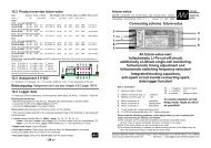
Connections to saddle (“hump”) packs:<br />
An ideal method of connecting the individual<br />
measurement wires in the case of factorymade<br />
saddle packs is to use the small sockets<br />
which are designed to accept the discharge<br />
resistances for the individual cells.<br />
Alternatively you can make up a saddle<br />
pack discharge box precisely for this measurement<br />
task, by soldering a measurement<br />
cable to the pairs of contacts which are<br />
located over each cell connector.<br />
Caution: it only makes sense to use factory-assembled<br />
soldered packs for this purpose;<br />
the transfer resistances are too high<br />
for measuring individual cells.<br />
Connections to battery "sticks":<br />
If your stick packs are not fitted with discharge<br />
sockets, you can "make do" by soldering<br />
the measurement wires to pins, and<br />
slipping the pins under the heat-shrink<br />
sleeve.<br />
Single cells:<br />
Single cells should be clamped together in<br />
the form of sticks, fitting a plate (ideally consisting<br />
of woven copper cell link braid) between<br />
the cells. The measurement wires are<br />
soldered permanently to these plates.<br />
The cells can be supported in a U-shaped<br />
or V-shaped channel, for example. Even<br />
better, cut slots in a plastic tube to line up<br />
with the cell joints, fit the metal plates in the<br />
slots and press the cells together with a<br />
spring (see photos on page 30).<br />
Fitting the "sensor wires":<br />
If only one measurement wire is used between<br />
the cells to pick up the voltage, the<br />
contact from cell to cell must really be<br />
100%, otherwise any slight contact resistance<br />
will be assumed to be cell resistance,<br />
and the measurement will be incorrect. For<br />
4 cells you can use two wires per cell, which<br />
should be connected in the sequence<br />
shown in brackets (see page 27).<br />
Sequence of measurement wires:<br />
The order of the measurement wires should<br />
be coded using different colours, as it is essential<br />
to maintain the correct sequence, so<br />
that the PC analysis software (winsoft) can<br />
show the correct voltage for each cell in the<br />
pack.<br />
The colours of the wires are based on the colour<br />
code for electronic components which is<br />
in standard use throughout the world:<br />
schulze<br />
elektronik<br />
gmbh<br />
Page 29<br />
(exception: wire 7). 4 cells:<br />
0: black cell 1 - (cell 1 -)<br />
1: brown cell 1 + (cell 1 +)<br />
2: red cell 2 + (cell 3 -)<br />
3: orange cell 3 + (cell 3 +)<br />
4: yellow cell 4 + (cell 5 -)<br />
5: green cell 5 + (cell 5 +)<br />
6: blue cell 6 + (cell 7 -)<br />
7: white cell 7 + (cell 7 +)<br />
4-cell mode: cells 2, 4 and 6 absent.<br />
The black wire 0 must make very good contact<br />
with the pack as it carries the power supply<br />
to the 12-bit A/D converter.<br />
Wire No. 7 is a special case: between the black<br />
and white wires the voltage of the en-tire 7cell<br />
pack can be measured. The winsoft<br />
program assumes this to be the case.<br />
If you wish to measure batteries consisting of<br />
fewer cells, then this white wire must also<br />
be connected to the positive terminal of the<br />
last cell to transfer the overall voltage of the<br />
pack in every case.<br />
This even applies to packs of cells when you only<br />
wish to measure the overall voltage.<br />
With high-current charge processes in particular, the<br />
<strong>ecolader</strong> is not able to determine and display the<br />
exact voltage of a battery, due to the cable resistances<br />
inside and outside the <strong>charger</strong>. If you require<br />
exact voltage values, you must use the<br />
12-Bit measurement procedure. i. e. you<br />
should connect the black measurement wire to<br />
the negative terminal of the first cell in the pack,<br />
and the white wire to the last cell in the pack.<br />
If you use the 4-point measurement method<br />
(using the cell holder shown on page 27)<br />
you may find that “cells” 2, 4, and 6 exhibit a<br />
low voltage when the pack is on charge.<br />
These values are due to the transfer resistance<br />
of the clamp connection.<br />
To ensure that all measurement results are reliable<br />
and reproducible, the voltage data is<br />
not transferred via the 8 measurement wires<br />
if more than one battery is connected to the<br />
<strong>ecolader</strong> select.<br />
To avoid error messages (Voltage > MAX) when<br />
the sensor wires are connected, it is important<br />
when discharging or charging always to connect<br />
the negative terminal of the charge cable<br />
first, followed by the positive terminal,<br />
when the sensor wires are connected.<br />
You will obtain false measurements of the last<br />
cell in the pack if the battery is measured<br />
during a charge process and not, as is usual,<br />
during a discharge. The car battery /<br />
mains PSU voltage must not exceed 12 V.<br />
schulze elektronik gmbh • prenzlauer weg 6 • D-64331 weiterstadt • tel: 06150/1306-5, fax: 1306-99<br />
internet: http://www.schulze-elektronik.com e-mail: mail@schulze-elektronik.com