ecolader: rapid discharger/charger series - Schulze Elektronik GmbH
ecolader: rapid discharger/charger series - Schulze Elektronik GmbH
ecolader: rapid discharger/charger series - Schulze Elektronik GmbH

Create successful ePaper yourself
Turn your PDF publications into a flip-book with our unique Google optimized e-Paper software.
<strong>ecolader</strong>: <strong>rapid</strong> <strong>dis<strong>charger</strong></strong>/<strong>charger</strong> <strong>series</strong><br />
Operating instructions for software V1.04, date of issue 05 MAY 1998<br />
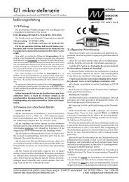
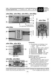
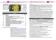
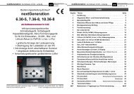
Heat-sink. Caution,<br />
temperature may<br />
reach 100°C<br />
Power cable<br />
to 12 V ... 13.8 V<br />
DC power<br />
supply<br />
Charge/<br />
discharge<br />
socket 1<br />
Left side:<br />
Auxiliary<br />
sockets<br />
schulze<br />
elektronik<br />
gmbh<br />
Page 1<br />
Display for<br />
battery data,<br />
program and<br />
<strong>charger</strong> info<br />
Side socket:<br />
8-channel 12-bit<br />
A/D converter<br />
Charge/discharge<br />
socket 2<br />
socket 3<br />
menü, akku1, akku2, akku3, spezial = Control buttons<br />
Dear fellow modeller,<br />
Your choice of the <strong>ecolader</strong> provides you with a micro-computer controlled High-Tech <strong>charger</strong> and<br />
<strong>dis<strong>charger</strong></strong> developed and built in Germany.<br />
As market leaders in the field of automatic <strong>rapid</strong> <strong>charger</strong>s for model aircraft, our aim with this device<br />
was to produce a high-quality <strong>charger</strong> for the model car driver with all the functionality you need.<br />
Thanks to the <strong>charger</strong>'s facility to charge at all three outputs using default settings, you do not need<br />
to operate any controls on the unit - apart from selecting a charge or discharge program.<br />
As a "pro" driver you will appreciate the <strong>ecolader</strong>'s comprehensive adjustment facilities, all aimed at<br />
charging the maximum possible quantity of energy into your packs by means of a range of charging<br />
techniques, including the optimised <strong>Schulze</strong> Refresh process for revitalising tired batteries.<br />
Combination programs (charge/discharge or discharge/charge) are provided to help you maintain,<br />
balance and measure the condition of your packs.<br />
The <strong>ecolader</strong> select can be used with a supplementary resistance to increase the already very<br />
high discharge current still further. Batteries are measured using a precision 12-bit A/D converter,<br />
and battery data can be transferred to the PC for analysis and archiving.<br />
Section Subject Page<br />
1 Warnings . . . . . . . . . . . . . . . . . . . . . . . . . . . . . . . . . . . . . 2<br />
2 How to obtain reliable, trouble-free operation . . . . . . . . . . . . . . . . . 3<br />
3 Fitting the CE tube . . . . . . . . . . . . . . . . . . . . . . . . . . . . . . . . 4<br />
4 Terminology . . . . . . . . . . . . . . . . . . . . . . . . . . . . . . . . . . . 4<br />
5 Useful information on battery care . . . . . . . . . . . . . . . . . . . . . . 5<br />
6 Basic operations . . . . . . . . . . . . . . . . . . . . . . . . . . . . . . . . . 6<br />
7 Connecting the unit, setting the standard values . . . . . . . . . . . . . . . 8<br />
8 Changing the default characteristics (summary table) . . . . . . . . . . . . . 10<br />
8.1-8.24 Description of <strong>charger</strong> characteristics . . . . . . . . . . . . . . . . . . . . . 10-27<br />
9 Monitor displays on the LCD screen . . . . . . . . . . . . . . . . . . . . . . 27<br />
10 Auxiliary sockets on the side panels . . . . . . . . . . . . . . . . . . . . . . 28<br />
11 Data interface . . . . . . . . . . . . . . . . . . . . . . . . . . . . . . . . . . . 30<br />
12 winsoft PC analysis program . . . . . . . . . . . . . . . . . . . . . . . . . . 30<br />
13 Legal matters . . . . . . . . . . . . . . . . . . . . . . . . . . . . . . . . . . . 31<br />
14 Specification, auxiliary socket pin-outs, data formats . . . . . . . . . . . . . 32<br />
15 Error messages and their causes . . . . . . . . . . . . . . . . . . . . . . . . 34<br />
16 Fault-finding, fault correction . . . . . . . . . . . . . . . . . . . . . . . . . . 35<br />
17 Service questionnaire . . . . . . . . . . . . . . . . . . . . . . . . . . . . . . 36<br />
schulze elektronik gmbh • prenzlauer weg 6 • D-64331 weiterstadt • tel: 06150/1306-5, fax: 1306-99<br />
internet: http://www.schulze-elektronik.com e-mail: mail@schulze-elektronik.com
Page 2 <strong>ecolader</strong>: <strong>rapid</strong> <strong>dis<strong>charger</strong></strong>/<strong>charger</strong> <strong>series</strong><br />
1 Warnings<br />
Injury hazard! Watch out for sharp corners<br />
and edges when handling the <strong>charger</strong> (heatsink).<br />
The CE symbol is not an excuse to handle the<br />
<strong>charger</strong>, the power supply or the batteries<br />
connected to it carelessly.<br />
Before you connect the unit to a 12 V car battery:<br />
switch off the vehicle's engine. The<br />
<strong>charger</strong> is only approved for use with a stationary<br />
vehicle whose engine is stopped.<br />
The unit must only be operated with the original,<br />
unmodified connecting cables.<br />
Avoid short-circuits between the charge outputs<br />
and the car bodywork. To be on the safe<br />
side, place the <strong>charger</strong> on the ground.<br />
The charge cables and charge outputs must<br />
never be connected to each other or shorted<br />
in any way; the result would inevitably be<br />
damage to the unit and/or the battery. To<br />
avoid short-circuits between the banana<br />
plugs on the charge cable, always connect<br />
the charge cable to the <strong>charger</strong> first, and<br />
only then connect the battery. Keep to the<br />
reverse order when disconnecting. Our<br />
safety charge cables eliminate the hazard of<br />
exposed banana plug contacts, as they are<br />
protected by a spring-loaded insulating<br />
sleeve.<br />
To meet CE requirements the length of the<br />
charge cable must not exceed 20 cm.<br />
The temperature of the <strong>ecolader</strong>'s heat-sink<br />
can easily reach 100°C when running. Take<br />
care not to touch it to avoid burns!<br />
There is always a risk of explosion when Ni-Cd<br />
batteries are being <strong>rapid</strong>-charged. For this<br />
reason it is important not to leave the <strong>charger</strong><br />
unsupervised during <strong>rapid</strong>-charging.<br />
Place the unit and the batteries connected to it<br />
on a non-flammable, heatproof and electrically<br />
non-conducting surface when in use.<br />
Keep inflammable and volatile substances and<br />
objects well clear of the charging station when<br />
the system is in use.<br />
As a precaution we recommend that you remove<br />
batteries from the model for charging.<br />
When charging internal transmitter batteries the<br />
maximum permissible charge current (dictated<br />
by the transmitter circuit board) must<br />
be observed by setting the current manually.<br />
The usual rate is 0.5 - 2 A; see radio manufacturer's<br />
specification.<br />
Note that fully-charged cells become very hot<br />
when "peaked" using the delay setting on<br />
the charge termination circuit.<br />
Never attempt to use the <strong>ecolader</strong> with a car<br />
battery when the battery itself is on charge<br />
on a battery <strong>charger</strong>. This will damage the<br />
<strong>charger</strong>! Use a stabilised 13.8 V DC voltage<br />
source which is current overload protected.<br />
Protect the <strong>ecolader</strong> from damp, water, shock<br />
and pressure loads.<br />
Do not continue to use the <strong>charger</strong> if it exhibits<br />
a fault, or if the screen displays an error<br />
message.<br />
Charging fewer than four cells:<br />
The peak detection termination circuit may trip<br />
prematurely, with a delay, or even not at all!<br />
Reason: the "kink" in the voltage curve of<br />
high-capacity cells when the charge current<br />
is low and the number of cells small is very<br />
slight.<br />
If you use a low number of cells the <strong>charger</strong><br />
will not reach the normal maximum charge<br />
current to prevent overheat.<br />
The following types of battery / pack / cell must<br />
not be connected to the unit:<br />
- Packs consisting of different types of cell<br />
- Mixtures of old and new cells, or cells of<br />
different makes<br />
- Non-rechargeable batteries (i.e. dry cells)<br />
- Lithium-Ion batteries<br />
- Batteries which are not expressly stated by<br />
the manufacturer to be suitable for the high<br />
charge currents which this unit supplies<br />
- Faulty or damaged single cells<br />
- Fully charged or hot batteries<br />
- Batteries with an integral charge or cut-off<br />
circuit<br />
- Batteries which are an integral part of a<br />
device, or are electrically connected to other<br />
components<br />
schulze elektronik gmbh • prenzlauer weg 6 • D-64331 weiterstadt • tel: 06150/1306-5, fax: 1306-99<br />
internet: http://www.schulze-elektronik.com e-mail: mail@schulze-elektronik.com
<strong>ecolader</strong>: <strong>rapid</strong> <strong>dis<strong>charger</strong></strong>/<strong>charger</strong> <strong>series</strong><br />
Operating instructions for software V1.04, date of issue 05 MAY 1998<br />
2 How to obtain reliable, trouble-free operation<br />
Be sure to protect the <strong>charger</strong> from direct sunshine,<br />
dust, damp and rain. If the unit<br />
should get wet, let it dry out thoroughly and<br />
have it checked and cleaned before re-use.<br />
The case openings must never be obstructed or<br />
sealed.<br />
The <strong>charger</strong> produces considerable heat when<br />
working - up to 100°C at the heat-sink; don't<br />
burn yourself! - and it is important to provide<br />
an effective means of dissipating the heat.<br />
This applies in particular after a high-rate<br />
charge of a pack of few cells, or a high-current<br />
discharge process, when the unit<br />
should be allowed plenty of time to cool<br />
down before re-use.<br />
Check the <strong>charger</strong> regularly - cables, connectors,<br />
case and screen - for possible damage<br />
and intermittent contacts.<br />
Keep the charge leads (between <strong>charger</strong> and<br />
pack) as short as possible. CE directives require<br />
cables no longer than 20 cm. The cables<br />
attached to the battery must also be as<br />
short as possible, and the conductor crosssection<br />
should be no less than 2.5 mm2 -<br />
even for a receiver battery!<br />
Use high-quality connectors exclusively (goldcontact<br />
types) at both ends of the charge<br />
cable, and run each cable through one of<br />
the ferrite tubes (CE tube) supplied with the<br />
<strong>charger</strong>. These tubes are essential in order<br />
to meet CE requirements (see Section 3).<br />
Twist cables together to avoid interference.<br />
Always keep to the battery manufacturer's recommended<br />
charge currents and times. You<br />
should only charge packs which are expressly<br />
stated to be suitable for <strong>rapid</strong>-charging.<br />
In theory the unit can be powered by a stabilised<br />
mains power supply, but we cannot<br />
recommend this generally.<br />
If you insist on using the <strong>charger</strong> in this way,<br />
you must check carefully to ensure that your<br />
combination of <strong>charger</strong> / power supply<br />
works correctly under all circumstances.<br />
schulze<br />
elektronik<br />
gmbh<br />
Page 3<br />
Many transmitters feature a reverse-flow diode<br />
which must be by-passed if you wish to <strong>rapid</strong>-charge<br />
the battery. Be sure to read the<br />
RC system instructions before you try this.<br />
Make it a habit to check that the charge quantity<br />
indicated is roughly what you expected<br />
after the unit has switched off automatically.<br />
This is the easy and reliable way to notice<br />
when and if the unit detects a "battery full"<br />
state erroneously. Premature charge termination<br />
is most likely with deep-discharged<br />
packs, and/or packs of few cells (carry out a<br />
test charge first!), although particular cell<br />
types tend to cause problems.<br />
Caution: if you fail to notice that a battery is<br />
not fully charged, using that pack in a model<br />
aircraft could easily cause a crash!<br />
The sequence of letters "a", "b"... indicates the<br />
probability of a full charge, but the "full"<br />
message does not necessarily follow them.<br />
The letters sequence often appears at the<br />
start of the charge, especially if deep-discharged<br />
cells are in use.<br />
Cells to be recharged together must be connected<br />
by soldering if the fully automatic<br />
programs are to function correctly. Don't use<br />
battery boxes with spring contacts!<br />
The <strong>ecolader</strong> only sets the charge current calculated<br />
as optimum for the battery if that<br />
current does not exceed any of the permissible<br />
parameters for the <strong>charger</strong>.<br />
Results with Ni-MH batteries are good provided<br />
that you set the charge current manually,<br />
and keep to charge currents of 1 C or less.<br />
The unit needs about 10 minutes time to detect<br />
the correct number of cells of a deeply discharged<br />
pack.<br />
If the voltage at battery socket 3 is < 0.5 V the<br />
<strong>charger</strong> assumes reversed polarity.<br />
schulze elektronik gmbh • prenzlauer weg 6 • D-64331 weiterstadt • tel: 06150/1306-5, fax: 1306-99<br />
internet: http://www.schulze-elektronik.com e-mail: mail@schulze-elektronik.com
Page 4 <strong>ecolader</strong>: <strong>rapid</strong> <strong>dis<strong>charger</strong></strong>/<strong>charger</strong> <strong>series</strong><br />
3 Fitting the CE tube<br />
Requirements:<br />
- The conductor cross-section of the charge cables<br />
should be 2.5 mm2 .<br />
- One insulator should be coloured red (positive<br />
terminal +) and the other black (negative terminal<br />
-).<br />
- The charge cable should be no longer than 20<br />
cm (including the length of cable attached to<br />
the battery!) in order to meet CE requirements.<br />
1. Solder a banana plug to each cable. You can<br />
avoid short-circuits by using our special safety<br />
banana plugs with spring-loaded insulators.<br />
2. Tie the two cables together about 4 cm from<br />
the banana plugs using one of the cable ties<br />
supplied.<br />
3. Slip the EMF tube supplied onto the free end<br />
of the charge cable.<br />
4. Tie the two cables together immediately after<br />
the tube using the second cable tie (see illustration).<br />
Cable ties<br />
5. Twist the cables together and/or hold them<br />
together with pieces of heat-shrink sleeving.<br />
6. Now solder the battery connector to the exposed<br />
wire ends. Don't forget to fit the heatshrink<br />
sleeves on the wires beforehand.<br />
A factory-made charge cable complete with<br />
safety banana plugs and CE tube is available<br />
from us under CE-kab-i6 (see illustration).<br />
The sensor cable for the <strong>ecolader</strong> select is<br />
made up in the same way using a tube and two<br />
cable ties, but the tube should be located up to<br />
5 cm from the 10-pin socket.<br />
4 Terminology<br />
Final discharge voltage: The final discharge voltage<br />
represents the discharge limit for the pack.<br />
The voltage is determined by the chemical composition<br />
of the battery. Below this voltage the cells enter<br />
the deep-discharge zone, where there is a danger<br />
of individual cells suffering reversed polarity<br />
and possible permanent damage.<br />
Balancing: Alternating discharge / charge cycles,<br />
repeated where necessary, aimed at restoring the<br />
full (nominal) capacity. This process is especially<br />
effective after a long period of non-use (e.g. after<br />
purchase, or after several weeks' lay-off), or in an<br />
attempt to eliminate the memory effect (see below).<br />
Balancing has the effect of converting a<br />
coarse crystalline structure inside the cell (low capacity)<br />
into a fine crystalline one (high capacity).<br />
Memory effect: this term is used for the effect on<br />
battery capacity (shorter motor runs) of repeated<br />
partial charges/discharges. This phenomenon can<br />
be eliminated by carrying out several balancing<br />
processes, in which the packs are taken down to<br />
their final discharge voltage, or even slowly reduced<br />
to a cell voltage of 0 V by means of resistances<br />
across each cell separately.<br />
Final charge voltage: the voltage which represents<br />
the charge (or capacity) limit of the battery. At this<br />
point the <strong>charger</strong> switches from a high current to a<br />
low maintenance rate (trickle charge). Further <strong>rapid</strong>-charging<br />
at this point would lead to overheating<br />
and permanent cell damage.<br />
Power-On (reset): State of <strong>ecolader</strong> when just connected<br />
to the car battery.<br />
Ready message: unit ready to carry out your selected<br />
program (batteries not yet connected).<br />
C: Coulomb / Capacity: unit of measurement for<br />
the quantity of charge; in conjunction with the<br />
charge current information this unit is used to calculate<br />
the recommended charge current of a battery<br />
of a particular capacity. Example: if the charge<br />
or discharge current of a 500 mAh pack is 50 mA,<br />
we speak of a charge or discharge rate of one<br />
tenth C (C/10 or 1/10 C).<br />
A, mA: unit of measurement for the charge or discharge<br />
current. 1A = 1000mA (A=Ampere, mA=Milliampere)<br />
Ah, mAh: unit of measurement for the capacity of a<br />
battery (Amps multiplied by time unit; h = hour). If a<br />
battery is charged for one hour at a current of 2 A,<br />
a total of 2 Ah of energy has been fed into it. The<br />
battery has been supplied the same quantity of energy<br />
(2 Ah) if it is charged for 4 hours at 0.5 A, or<br />
15 minutes (= 1/4 hour) at 8 A.<br />
schulze elektronik gmbh • prenzlauer weg 6 • D-64331 weiterstadt • tel: 06150/1306-5, fax: 1306-99<br />
internet: http://www.schulze-elektronik.com e-mail: mail@schulze-elektronik.com
<strong>ecolader</strong>: <strong>rapid</strong> <strong>dis<strong>charger</strong></strong>/<strong>charger</strong> <strong>series</strong><br />
Operating instructions for software V1.04, date of issue 05 MAY 1998<br />
5 Useful information about<br />
battery care<br />
5.1 General information:<br />
A cold cell cannot absorb so much current as a<br />
warm one, and for this reason you can expect<br />
seasonal differences in charge behaviour<br />
if you use the fully automatic charge<br />
current calculation. In Winter your packs will<br />
not accept as much charge as in Summer.<br />
The lower the internal resistance of the battery,<br />
the higher the <strong>charger</strong> can push the charge<br />
rate. Note that a <strong>charger</strong> which calculates<br />
the charge rate automatically also takes<br />
into account the resistance of the charge<br />
cables. So: use short cables of large<br />
conductor cross-section (even for receiver<br />
battery cables). Do not charge via a<br />
switch or switch harness!<br />
5.2 Nickel-Cadmium batteries:<br />
Selecting the charge current (manual selection):<br />
Charge current = 2 x C (C = nominal battery<br />
capacity)<br />
If a pack is not regularly maintained, or is<br />
brand-new, it can often take several discharge/charge<br />
cycles for it to reach a completely<br />
balanced condition.<br />
As a general rule you can calculate a suitable<br />
discharge current for an accurate measurement<br />
of battery capacity as follows:<br />
Discharge current = 1/10 C (C = nominal<br />
battery capacity)<br />
In practice however, higher discharge currents<br />
can be tolerated, depending on the<br />
degree of accuracy you require.<br />
Our automatic method of calculating charge<br />
current is the subject of a patent application,<br />
and provides optimum protection to your Ni-<br />
Cd packs against damage. The reduced<br />
charge current towards the end of the process<br />
ensures maximum energy absorption<br />
and minimal temperature rise, as can easily<br />
be ascertained in comparison with conventional<br />
constant current charging procedures.<br />
schulze<br />
elektronik<br />
gmbh<br />
Page 5<br />
Note that the lower charge current which is applied<br />
with 1-5 cells, combined with the small<br />
voltage "kink" with high-capacity packs, may<br />
lead to difficulties in detecting the Peak<br />
when such packs are <strong>rapid</strong>-charged.<br />
To erase the memory effect it is common practice<br />
amongst model car operators to discharge<br />
each cell (individually!) via resistor of<br />
about 68 Ohm.<br />
This process deliberately "unbalances" the<br />
pack.<br />
However, this procedure may result in the<br />
<strong>charger</strong> terminating the process prematurely<br />
of the subsequent charge.<br />
Storage: Ni-Cd batteries must therefore be discharged<br />
down to the final discharge voltage<br />
after use, in order to prevent the occurrence<br />
of the memory effect, and to maintain the<br />
pack's full capacity.<br />
5.3 Lead-acid batteries:<br />
Lead-acid batteries cannot be charged using<br />
the <strong>ecolader</strong>. However, in the interests of<br />
completeness we are providing a little background<br />
information on the subject.<br />
The characteristics of lead-acid batteries are<br />
entirely different from those of Ni-Cd sintered-cell<br />
packs, which are used as the<br />
power source in model aircraft, model cars<br />
and hydroplane boats. Lead-acid batteries<br />
can only be discharged at relatively low currents<br />
if their full capacity is to be exploited,<br />
and/or their voltage is not to collapse too<br />
far.<br />
As with discharging, these batteries may only<br />
be charged at low currents (0.1 C, voltagelimited).<br />
The charge period is then in the order<br />
of 20 hours.<br />
The nominal capacity (i.e. charge duration) can<br />
be reduced very quickly by incorrect maintenance<br />
(overcharging, many 100% discharges<br />
and especially deep discharges). Read<br />
the instructions supplied with your batteries.<br />
Storage: if lead-acid batteries are to be maintained<br />
at full capacity, they must be stored<br />
in the charged state, in contrast to Ni-Cd<br />
packs.<br />
schulze elektronik gmbh • prenzlauer weg 6 • D-64331 weiterstadt • tel: 06150/1306-5, fax: 1306-99<br />
internet: http://www.schulze-elektronik.com e-mail: mail@schulze-elektronik.com
Page 6 <strong>ecolader</strong>: <strong>rapid</strong> <strong>dis<strong>charger</strong></strong>/<strong>charger</strong> <strong>series</strong><br />
6 Basic operations:<br />
6.1 Button assignment at the standard working<br />
level:<br />
After connecting the <strong>ecolader</strong> to the car battery<br />
or a suitable mains power supply the LCD<br />
screen shows the standard working level.<br />
esc, enter, +, -:<br />
no function assigned.<br />
spezial (special):<br />
This button is used to select the display<br />
mode of the two-line LCD screen.<br />
See Section 6.4 for further details.<br />
menü (menu):<br />
This button is used to branch off into the<br />
menu level of the <strong>ecolader</strong>, to alter currents,<br />
programs and device parameters.<br />
Before branching into the menu level, press<br />
one of the three akku buttons, so that you see<br />
in the first line of the LCD screen the parameters<br />
of your selected battery.<br />
In "One-battery-full-screen" mode you can only<br />
alter the parameters of the previously selected<br />
battery number.<br />
akku 1, akku 2, akku 3 (battery 1, 2, 3):<br />
If you give a short press on one of these buttons<br />
when in "One-battery-full-screen" mode<br />
the display switches over to show data for the<br />
battery you have selected.<br />
In "Two-battery-display" mode a brief press<br />
on the akku 2 or akku 3 button switches the<br />
second line of the screen to show battery 2<br />
or battery 3 constantly.<br />
akku 1, akku 2, akku 3:<br />
If you hold these buttons pressed in you will<br />
see for a period of about 3 seconds an expanded<br />
status display on the selected battery,<br />
in addition to the switch-over as described<br />
above (e.g. A1 A1 disconnected<br />
disconnected, disconnected A2<br />
A2<br />
charging(1) charging(1) 1.0A 1.0A). 1.0A<br />
In addition the currently charged-in or discharged<br />
charge quantity is shown in line 2 of<br />
the screen.<br />
Holding the akku button pressed in extends<br />
the 3-second period mentioned above.<br />
In the combination programs you can display<br />
the charge / discharge quantities of all previously<br />
completed phases by pressing the +<br />
and - button within the 3-second period mentioned<br />
above. The quantity value of the current<br />
phase is not updated during this time.<br />
(See also Section 9, monitor displays)<br />
6.2 Button assignment at the menu level:<br />
esc, enter:<br />
return to working level.<br />
+, -: Select function:<br />
Leafs through within a table of functions<br />
which are displayed in the second<br />
line of the screen.<br />
Functions are, for example, a simple<br />
display function of device number, selecting<br />
the charge or discharge current,<br />
selecting a charge or discharge program,<br />
and configuring safety functions<br />
such as limiting the maximum charge<br />
time.<br />
The <strong>ecolader</strong> select offers additional features,<br />
including owner's name, date,<br />
time of day, and clock-controlled starting<br />
time for programs (each battery separately).<br />
akku 1, akku 2, akku 3, spezial:<br />
Depending on whether one of the above<br />
named functions is battery-specific or<br />
<strong>charger</strong>-specific, you must press one of<br />
the akku buttons or the spezial button to<br />
select or alter a function. You then move<br />
to the Value (value change) level.<br />
Note: In "One-battery-full-screen" mode<br />
only one of the three akku buttons is active.<br />
User guidance:<br />
In the first line of the screen you see the<br />
current value; in the second line the associated<br />
function.<br />
In each case you will see the buttons<br />
which are required or assigned at the<br />
right-hand edge of the screen, in order<br />
to change the value of a function, such<br />
as the value of the charge current or the<br />
charge termination criterion.:<br />
?+- for the + and/or - button, for leafing<br />
through within "select function", e.g. in<br />
order to have a quick look at the current<br />
settings of the <strong>charger</strong>.<br />
?e for enter or esc button<br />
?a for akku 1, 2, 3 button<br />
?s for spezial button<br />
schulze elektronik gmbh • prenzlauer weg 6 • D-64331 weiterstadt • tel: 06150/1306-5, fax: 1306-99<br />
internet: http://www.schulze-elektronik.com e-mail: mail@schulze-elektronik.com
<strong>ecolader</strong>: <strong>rapid</strong> <strong>dis<strong>charger</strong></strong>/<strong>charger</strong> <strong>series</strong><br />
Operating instructions for software V1.04, date of issue 05 MAY 1998<br />
6.3 Button assignment at the Value level:<br />
When you have selected a variable battery-specific<br />
value, the left-hand side of<br />
the first line of the screen shows the battery<br />
to which the displayed value refers<br />
(e.g.: A2: A2:). A2:<br />
+, -: Select value:<br />
Leafs through in a table of values which<br />
are displayed individually in the second<br />
line of the screen.<br />
Values may be, for example, different<br />
charge current values, charge / discharge<br />
programs which you can select,<br />
but also device parameters (e.g. selecting<br />
the max. overall current consumption<br />
for the <strong>charger</strong>). The displayed value<br />
which you wish to use must then be selected<br />
by pressing the enter button.<br />
enter:<br />
esc:<br />
Returns to the menu level, accepting<br />
the value shown in the second line of the<br />
screen.<br />
Returns to the menu level without<br />
changing the earlier value.<br />
spezial:<br />
Sets the just selected value to a default<br />
(standard) value (= "enter" function with<br />
value already defined). An example is car<br />
battery low voltage 11200 mV (11.2 V).<br />
Complex input functions:<br />
Multiple select facilities (e.g. the date)<br />
are first selected as a group using the<br />
akku buttons before the values are entered:<br />
Date using akku 1 (T = batt 1)<br />
Month using akku 2 (M= batt 2)<br />
Year using akku 3 (J = batt 3)<br />
Default value withspezial (s)<br />
In this case the second line of the<br />
screen helps to guide the user:<br />
Date:T1,M2,Y3,s<br />
Date:T1,M2,Y3,s<br />
6.4 Special functions:<br />
schulze<br />
elektronik<br />
gmbh<br />
Page 7<br />
Selecting the LCD screen display mode:<br />
(leaf through using + -, select with enter)<br />
"One-Battery-Screen" mode: (default)<br />
The 2 lines of the screen display virtually all the<br />
adjustment and operational parameters of a single<br />
battery. In this mode the battery number is<br />
enclosed by two black fields (squares) at the<br />
start of the second line of the screen.<br />
"Two-battery-Screen" mode:<br />
The second line of the screen shows battery 2 or<br />
battery 3. In this mode the battery 3 display<br />
shows a black field in the first and last thirds of<br />
the second line.<br />
"Temperature display on or off":<br />
The second line of the LCD screen shows the<br />
battery temperature (full-screen mode only, has<br />
priority over car battery voltage display).<br />
"Car battery voltage on or off":<br />
The second line of the LCD screen shows the<br />
power supply voltage (in "Two-battery-display"<br />
mode only when battery 3 is displayed). Useful<br />
when the <strong>ecolader</strong> is powered by your car battery.<br />
Naturally, the information otherwise shown<br />
at this position is no longer visible.<br />
"Discharge and charge quantity on or off":<br />
In two-battery-display mode the charge/discharge<br />
quantity can be shown instead of battery voltage.<br />
"Time of day on or off":*<br />
The <strong>ecolader</strong> select shows the time of day in the<br />
first line of the LCD screen.<br />
Note: the information normally shown at this position<br />
is overwritten by these displays.<br />
Switching off the "full" or "empty" beep:<br />
Press any button.<br />
We suggest that you use the esc button, to avoid<br />
making inadvertent changes to device settings.<br />
Display of charge/discharge quantity after an error:<br />
Press the corresponding akku x button.<br />
6.5 Miscellaneous information<br />
For charging 6 cells a supply voltage of 12 V is<br />
sufficient. The <strong>ecolader</strong> stays cooler with a 12 V<br />
supply than with 13.8 V during the charge process.<br />
When charging 7 cells you should use a fullycharged<br />
12 V battery (or 13.8 V mains PSU).<br />
If the <strong>ecolader</strong> is required to operate for long periods<br />
at high charge / discharge currents, we recommend<br />
that you connect a fan to the cooling<br />
fan socket on the left-hand side of the <strong>charger</strong>, in<br />
order to cool the heat-sink on the rear of the<br />
case. This will avoid the safety circuit tripping,<br />
which reduces current and/or switches the <strong>ecolader</strong><br />
off if its temperature reaches about 100°C.<br />
schulze elektronik gmbh • prenzlauer weg 6 • D-64331 weiterstadt • tel: 06150/1306-5, fax: 1306-99<br />
internet: http://www.schulze-elektronik.com e-mail: mail@schulze-elektronik.com
Page 8 <strong>ecolader</strong>: <strong>rapid</strong> <strong>dis<strong>charger</strong></strong>/<strong>charger</strong> <strong>series</strong><br />
7 Connecting the <strong>charger</strong>,<br />
setting the default values<br />
Please read Section 1 "Warnings" and Section<br />
2 "How to obtain reliable, trouble-free operation".<br />
There you will find valuable information<br />
which you should know before you attempt<br />
to connect and use the <strong>charger</strong>.<br />
7.1 Before connecting the unit<br />
Take the <strong>ecolader</strong> out of its box before using<br />
it, to ensure an adequate flow of cooling<br />
air when it is running.<br />
Do not connect the <strong>charger</strong> to the battery or<br />
batteries you wish to charge.<br />
Ensure that the power supply (12 V car battery,<br />
12-13.8 V mains PSU) is providing stable<br />
power without any unwanted effects.<br />
Ensure that the power supply is making really<br />
sound contact with the terminals of the<br />
<strong>ecolader</strong>. This is not possible with cheap<br />
banana plugs and car cigar lighter plugs,<br />
and these should therefore not be used.<br />
7.2 Switch on the power supply<br />
If you are using the car battery in your vehicle:<br />
- switch off the engine.<br />
If you are using a suitable mains PSU:<br />
- switch on the PSU beforehand.<br />
7.3 Connect the <strong>ecolader</strong> to the power supply<br />
The power terminal clips should be clamped<br />
onto the contact surfaces of the power supply<br />
maintaining correct polarity, working quickly<br />
and confidently.<br />
The integral fan will run briefly, then stop.<br />
After connection the screen will show the following<br />
Ready messages:<br />
eco-select eco-select eco-select V1.xx V1.xx V1.xx (or <strong>ecolader</strong>+)<br />
(c)schulze (c)schulze gmbh<br />
gmbh<br />
Date Date DayOfWk DayOfWk DayOfWk Time Time (not with <strong>ecolader</strong>+)<br />
schulzelektronik<br />
schulzelektronik schulzelektronik (or your name)<br />
A1 A1 ready ready Auto Auto C<br />
C<br />
nA1 A1 A1nL^_____q0000<br />
A1 L^_____q0000 ("One-Batt-Screen")<br />
If none of these messages appears, and<br />
you just see black squares, immediately<br />
disconnect the unit; damage may ensue if the<br />
<strong>charger</strong> is left in an undefined state. Wait 5<br />
seconds, repeat step 7.3.<br />
If nothing at all appears on the screen, you<br />
have probably connected + to -.<br />
7.4 Typical first charge process<br />
7.4.1 Default values (General Reset)<br />
If you don't know the configuration of the<br />
<strong>ecolader</strong> we recommend that you start by<br />
resetting the unit to the default values.<br />
This Reset sets the parameters for each battery<br />
output separately to values which are<br />
usable for almost all charging applications.<br />
At the same time the device parameters<br />
can be set to standard (default) values.<br />
Default value list: see Section 8.xx.<br />
Procedure:<br />
Press the menü button.<br />
The screen displays the following:<br />
A1:Auto A1:Auto C C (or other program)<br />
C/D-Program C/D-Program C/D-Program ?a<br />
?a<br />
Press the - (minus) button 6 x to reach the<br />
default value function.<br />
The screen now shows the following:<br />
- - - - - - - - - - - - - - - - - - - - - - -<br />
-<br />
DefaultValues?as<br />
DefaultValues?as<br />
Press the akku 1 button to set the default<br />
values for battery 1.<br />
The screen displays the following:<br />
DefaultValues?A1<br />
DefaultValues?A1<br />
<br />
<br />
Confirm with the enter button.<br />
The screen briefly shows the message:<br />
DefaultValues?A1<br />
DefaultValues?A1<br />
DefaultValues?A1<br />
executed<br />
executed<br />
and then switches back to:<br />
- - - - - - - - - - - - - - - - - - - - - - -<br />
-<br />
DefaultValues?as<br />
DefaultValues?as<br />
Press the spezial button to set the default<br />
values for the general operational parameters<br />
of the <strong>ecolader</strong>.<br />
The screen displays the following:<br />
DefaultValuesECO<br />
DefaultValuesECO<br />
<br />
<br />
Confirm with the enter button.<br />
The screen briefly shows the following:<br />
DefaultValuesECO<br />
DefaultValuesECO<br />
executed<br />
executed<br />
and then switches back to:<br />
- - - - - - - - - - - - - - -<br />
-<br />
DefaultValues?as<br />
DefaultValues?as<br />
DefaultValues?as<br />
Press the esc button to revert to the standard<br />
display.<br />
The screen now shows the following:<br />
schulze elektronik gmbh • prenzlauer weg 6 • D-64331 weiterstadt • tel: 06150/1306-5, fax: 1306-99<br />
internet: http://www.schulze-elektronik.com e-mail: mail@schulze-elektronik.com
<strong>ecolader</strong>: <strong>rapid</strong> <strong>dis<strong>charger</strong></strong>/<strong>charger</strong> <strong>series</strong><br />
Operating instructions for software V1.04, date of issue 05 MAY 1998<br />
A1 A1 ready ready auto auto C<br />
C<br />
nA1 A1 A1 A1nL^_____q0000<br />
A1 L^_____q0000<br />
L^_____q0000<br />
The first line of the screen shows that charge output 1<br />
(A1) is ready, and that the fully automatic charge program<br />
Auto C will be used.<br />
The second line features "A1" enclosed by two black<br />
fields (blocks), indicating that the "One-battery-fullscreen"<br />
mode has been selected, and that the data<br />
on the screen applies to battery 1.<br />
The slightly smaller L after A1 shows that the linear<br />
charge process has been set.<br />
The "pitched roof" (circumflex) symbol shows that<br />
peak-detect charge termination has been selected.<br />
The underlines are place-holders for the temperature, termination<br />
delay time or start time activation.<br />
The q stands before the 4-digit charge quantity display.<br />
The screen does not display the maximum charge current<br />
which the automatic calculation circuit could set.<br />
7.4.2 Displaying / altering the max. charge<br />
current for Battery 1:<br />
For a practice run, press the akku 1 button briefly, in<br />
order to switch the screen to "Display Battery 1"<br />
mode. (If, for example, you had previously pressed<br />
the akku 3 button, all the subsequent monitoring information<br />
would refer to battery 3).<br />
Now press the menü button once.<br />
(This takes you to Select Function for the charge /<br />
discharge program)<br />
Press the + button once.<br />
(This takes you to maximum charge current within Select<br />
Function)<br />
A1:I=6.0A<br />
A1:I=6.0A<br />
ChargeCur(max)?a<br />
ChargeCur(max)?a<br />
With the current value displayed in the first line, for<br />
example, the fixed C program could later charge a<br />
good 2 Ah pack without any problem.<br />
Pressing one of the akku 2 or akku 3 buttons in the<br />
selected "One-battery-full-screen" mode would be ignored<br />
(try it out), but in "Two-battery-display" mode<br />
this would switch to Select Value for the maximum<br />
charge current of Battery 2 to Battery 3.<br />
Now press the akku 1 button once.<br />
This takes you to Select Value for the maximum charge<br />
current for battery 1.<br />
The screen swaps the lines appropriately.<br />
ChargeCur(max)A1 ChargeCur(max)A1 (previously line 2)<br />
I=6.0A I=6.0A +-se +-se (previously line 1)<br />
I.e. the values which can be altered using the + and -<br />
buttons are always displayed in the second line of the<br />
screen.<br />
Pressing the + or - buttons at this point would now<br />
alter the current value, and pressing the enter button<br />
would select the new value.<br />
Please press the esc button twice at this point to return<br />
to the standard working level, as we do not want<br />
to change the charge current value at this juncture.<br />
schulze<br />
elektronik<br />
gmbh<br />
Page 9<br />
7.4.3 Starting a charge program<br />
Now the battery can be connected, taking<br />
care to maintain correct polarity.<br />
A short double-beep signals the start of an<br />
automatic program.<br />
The <strong>ecolader</strong> initially charges the battery at<br />
300 mA for about 15 seconds, in order to<br />
gain the information it needs to calculate the<br />
initial charge current.<br />
The first line of the screen shows the charge<br />
time, the charge voltage and the current<br />
charge current. When requested (by pressing<br />
the akku 1 button) the screen can show<br />
the current charged-in quantity. Note that<br />
the charge quantity can be displayed constantly<br />
if you press the spezial button.<br />
The charge current is then raised gradually<br />
over the first few minutes of the charge until<br />
it reaches the set maximum value, provided<br />
that the state of the battery and the number<br />
of cells in the pack allows this. Batteries of<br />
low capacity or high internal resistance will<br />
not reach maximum charge rate.<br />
If your 1700 or 2000 cells do not reach the 6<br />
A value, then your battery has either been<br />
poorly maintained, or has already "had it".<br />
The speed and extent to which the <strong>ecolader</strong><br />
applies charge current to your batteries, using<br />
the automatic charge process (patent<br />
applied for), is a direct indicator of the state<br />
of your batteries (low internal resistance =<br />
high charge current); although it may also<br />
indicate (just as accurately) that your charge<br />
cables are not up to the job (long or thin cables<br />
= high resistance = low charge current)!<br />
The automatic current calculation allows you<br />
to see the state of your battery immediately.<br />
7.4.3 "Full" display:<br />
Once a reset has been carried out (as described<br />
above), the battery's "full" condition<br />
is detected by the voltage peak method.<br />
The <strong>ecolader</strong> features a special form of<br />
"full" detection based on fuzzy logic, which<br />
makes it largely proof against interference.<br />
Professionals may wish to adjust some parameters<br />
of the peak termination system,<br />
but normally it is best to leave it at the default<br />
setting.<br />
The first line of the screen shows the charge<br />
time, an inverted f (= full) alternating with a<br />
t (= trickle charge), the final charge voltage<br />
and the reason for termination (PEAK), alternating<br />
with the charged-in quantity.<br />
The buzzer sounds briefly.<br />
schulze elektronik gmbh • prenzlauer weg 6 • D-64331 weiterstadt • tel: 06150/1306-5, fax: 1306-99<br />
internet: http://www.schulze-elektronik.com e-mail: mail@schulze-elektronik.com
Page 10 <strong>ecolader</strong>: <strong>rapid</strong> <strong>dis<strong>charger</strong></strong>/<strong>charger</strong> <strong>series</strong><br />
8 Altering the characteristics<br />
of the <strong>charger</strong><br />
Tabular symmary in the order of the table<br />
stored in the <strong>ecolader</strong>:<br />
To leaf through in the Function Table press<br />
the menü button once after the Ready message<br />
appears, with the <strong>ecolader</strong> connected<br />
to the power supply. This takes you to Select<br />
Function (8.15), printed below in bold<br />
type:<br />
[*] <strong>ecolader</strong> select only Page<br />
8.1* Calibrating the12-bit A/D-converter. 10<br />
8.2* Owner's name . . . . . . . . . . . 11<br />
8.3* Date . . . . . . . . . . . . . . . . 11<br />
8.4 Time of day . . . . . . . . . . . . 12<br />
8.5 Start time . . . . . . . . . . . . . 12<br />
8.6 Max. charge time . . . . . . . . . 13<br />
8.7 Max. charge quantity . . . . . . . 13<br />
8.8 Termination temperature . . . . . 14<br />
8.9 Termination delay . . . . . . . . . 14<br />
8.10 Termination check count . . . . . 15<br />
8.11 Termination sensitivity . . . . . . 15<br />
8.12 Termination criterion . . . . . . . 16<br />
8.13 Charge method . . . . . . . . . . 17<br />
8.14 Charge current . . . . . . . . . . 18<br />
8.15 Select charge/discharge program 18<br />
8.15.1* Sel.CD . . . . . . . . . . . . . 18<br />
8.15.2 Auto C . . . . . . . . . . . . . 19<br />
8.15.3 Fix C . . . . . . . . . . . . . 19<br />
8.15.4 Fix -D . . . . . . . . . . . . . 20<br />
8.15.5 Auto-D . . . . . . . . . . . . . 20<br />
8.15.6 Combi programs ...DC . . . . . 21<br />
8.15.7 Combi programs ...CD . . . . . 21<br />
8.16 Discharge current . . . . . . . . . 22<br />
8.17 Min. discharge voltage . . . . . . 22<br />
8.18 Cell count correction . . . . . . . 23<br />
8.19 No. of cycles of combi program . . 23<br />
8.20 Program after Power-On Reset . . 24<br />
8.21 Default values for batteries and <strong>charger</strong> 24<br />
8.22 Max. primary current . . . . . . . 25<br />
8.23 Car battery - min. voltage threshold . . 26<br />
8.24 Light / buzzer function at battery full . . 26<br />
8.25 Display device No. . . . . . . . . 27<br />
8.1* Calibrating 12-bit ADC<br />
Description:<br />
The <strong>ecolader</strong>-select features a precision 8channel<br />
12-bit analogue/digital converter<br />
which is used to measure the battery cells.<br />
To ensure that all 8 measurement channels<br />
work exactly "in step", the <strong>charger</strong> also features<br />
a calibration facility in the prototypes.<br />
The facility was incorporated to compensate<br />
for tolerances in the prototypes, which were<br />
fitted with input voltage divider resistors of<br />
5% tolerance.<br />
However, since production versions are<br />
equipped with 0.1% (!!!) resistors, the maximum<br />
error without calibration is well below<br />
1% (typical 3 mV) in any case, which means<br />
that this menu point is to be considered of<br />
checking the 8 channels of the A/D converter.<br />
Preparation:<br />
Connect the 10-pin plug on the eco-elast-<br />
0.40 Ohm discharge load resistor (accessory)<br />
to the measurement input on the righthand<br />
side of the <strong>charger</strong>. Note that this is an<br />
exceptional procedure. This sets all the<br />
measurement inputs to the same potential<br />
and connects them to a calibration voltage<br />
source. On no account connect the red banana<br />
plug of the discharge load resistor!<br />
Branch to the calibration menu:<br />
Press the spezial button, then:<br />
Carry out the 8 AD-channel voltages:<br />
Press the enter button, or<br />
Interrupt:<br />
Press the esc button<br />
Return to the Select Function menu:<br />
Both actions (above) takes you back automatically<br />
to the Select Function menu.<br />
Disconnect the 10-pin connector.<br />
Display:<br />
After a short waiting period the <strong>ecolader</strong><br />
confirms that output to the PC is complete<br />
by emitting a short beep.<br />
If you are using the winsoft software on<br />
your PC, you can observe the data output in<br />
the Info online window.<br />
schulze elektronik gmbh • prenzlauer weg 6 • D-64331 weiterstadt • tel: 06150/1306-5, fax: 1306-99<br />
internet: http://www.schulze-elektronik.com e-mail: mail@schulze-elektronik.com
<strong>ecolader</strong>: <strong>rapid</strong> <strong>dis<strong>charger</strong></strong>/<strong>charger</strong> <strong>series</strong><br />
Operating instructions for software V1.04, date of issue 05 MAY 1998<br />
8.2* Owner's name<br />
Description:<br />
The <strong>ecolader</strong>-select allows you to enter your<br />
name or telephone number in the 16-charcater<br />
screen area, so that you can easily<br />
identify your own <strong>charger</strong>.<br />
Activating the menu point:<br />
Press the spezial button.<br />
The first line of the screen then displays the<br />
key to the buttons, while the second line<br />
shows the name for you to change.<br />
You will see a cursor (small horizontal line)<br />
above the letter which can be changed, i.e.<br />
the cursor appears between the two lines of<br />
the display.<br />
Entering your name:<br />
The cursor is initially located above the first<br />
letter of the name.<br />
Press the + or - button until the screen<br />
shows the letter (or other character) which<br />
you want at that position.<br />
Release the button.<br />
Press the akku 3 button to confirm the new<br />
letter and move to the next letter on the<br />
right.<br />
If you make a mistake, press the akku 2<br />
button to move back one space.<br />
Press the akku 1 button between the first<br />
name and the last name to produce a<br />
space. The same applies at the end of the<br />
name if you want to erase the last few letters<br />
of the old name.<br />
The spezial button resets the name to<br />
schulzelektronik<br />
schulzelektronik.<br />
schulzelektronik<br />
Display:<br />
The screen shows a new letter or symbol, or<br />
a movement of the cursor, immediately after<br />
you press the appropriate button.<br />
Return to the Function Menu:<br />
Press enter to store the new name, or<br />
press esc to revert to the old name and discard<br />
your changes.<br />
8.3* Date<br />
schulze<br />
elektronik<br />
gmbh<br />
Page 11<br />
Description:<br />
The <strong>ecolader</strong>-select allows you to enter the<br />
current date, as it includes a special "timekeeper"<br />
module which maintains the date<br />
information even when the <strong>charger</strong> is<br />
switched off, and updates it daily. The date<br />
information is not required internally, unlike<br />
the time information (see Sections 8.4).<br />
Activating the menu point:<br />
Press the spezial button.<br />
This action shows the current date in the first<br />
line of the screen; the second line provides<br />
a brief key to the method of changing it:<br />
Day akku 1 button<br />
Month akku 2 button<br />
Year akku 3 button<br />
15.06.98 15.06.98 spezial button (default value)<br />
After you have pressed one of the buttons stated<br />
above you move on to<br />
Select value:<br />
Press the + or - button.<br />
The value to be changed appears in the<br />
second line of the screen.<br />
Confirm value:<br />
Press enter<br />
Interrupt:<br />
Press esc<br />
Note:<br />
The default value is roughly in the middle of<br />
the overall range, and serves as a good<br />
starting point when you need to set a completely<br />
new date.<br />
schulze elektronik gmbh • prenzlauer weg 6 • D-64331 weiterstadt • tel: 06150/1306-5, fax: 1306-99<br />
internet: http://www.schulze-elektronik.com e-mail: mail@schulze-elektronik.com
Page 12 <strong>ecolader</strong>: <strong>rapid</strong> <strong>dis<strong>charger</strong></strong>/<strong>charger</strong> <strong>series</strong><br />
8.4 Time of day, day of week*<br />
Description:<br />
The <strong>ecolader</strong>-select allows you to enter the<br />
current time of day, as it contains a special<br />
"timerkeeper" module which maintains the<br />
time information even when it is switched off,<br />
and updates the information every minute.<br />
The "day of the week" information is not required<br />
internally, unlike the "time of day" information<br />
which is part of the facility to start<br />
a program automatically at a particular time<br />
of day (see also Section 8.5).<br />
The <strong>ecolader</strong> + does not feature the "timekeeper"<br />
module, and you have to enter the<br />
time of day every time you connect it to the<br />
power source.<br />
Activating the menu point:<br />
Press the spezial button.<br />
When you have done this the first line of the<br />
screen displays the current day of the week*<br />
followed by the time of day. The second line<br />
shows a brief key to the buttons used to<br />
change the information:<br />
Day of week* menü button<br />
Hours (H1) akku 1 button<br />
Tens/min.(TM2) akku 2 button<br />
Minutes (M3) akku 3 button<br />
Mi Mi 12:30 12:30 spezial button (default value)<br />
Once you have pressed one of the buttons stated<br />
above you move to<br />
Select value:<br />
Press the + or - button.<br />
The value to be changed appears in the<br />
second line of the screen.<br />
Confirm value:<br />
Press enter<br />
Interrupt:<br />
Press esc<br />
Note:<br />
The default value is roughly in the middle of<br />
the overall range, and serves as a good<br />
starting point when you need to set a completely<br />
new time of week.<br />
It is not recommendable to change the unit's<br />
internal clock if a start time is activated or<br />
the Sel.LE program is used. This eliminates<br />
the danger of mistakes or unwanted starts.<br />
8.5 Start time<br />
Description:<br />
The <strong>ecolader</strong> includes the facility to enter<br />
the time of day at which the selected program<br />
is to start.<br />
Activating the menu point:<br />
Press the akku x button.<br />
When you have done this the first line of the<br />
screen displays the current day of the week<br />
followed by the time of day. The second line<br />
shows a brief key to the buttons used to<br />
change the information:<br />
Current time (T) menü button<br />
Hours (hh1) akku 1 button<br />
Tens / min.(tm) akku 2 button<br />
Minutes (mm3) akku 3 button<br />
off spezial button (or after POR)<br />
Once you have pressed one of the buttons stated<br />
above you move to<br />
Select value:<br />
Press the + or - button.<br />
The value to be changed appears in the<br />
second line of the screen.<br />
Confirm value:<br />
Press enter<br />
Interrupt:<br />
Press esc<br />
Notes:<br />
When you connect the <strong>charger</strong> to the car<br />
battery (Power On Reset) the start time is<br />
switched off.<br />
The start time can be set to any time in the<br />
following 24-hour period. Note: if you set a<br />
start time which is “lower” than the unit's internal<br />
clock time, the program will therefore<br />
not start immediately.<br />
The menü button copies the current time of<br />
day. This can also be used as the starting<br />
point for setting the start time.<br />
All 3 battery outputs can be started and operated<br />
automatically using completely different<br />
programs and at different times.<br />
Display:<br />
Near the Ready message (or in the second<br />
display line of the "one battery full screen")<br />
you will see a clock symbol if a start time<br />
has already been selected and set.<br />
If the battery has already been connected<br />
and is ready for use, but the start time has<br />
not yet been reached, the screen displays<br />
the following message:<br />
WaitUntil>hh:mm WaitUntil>hh:mm (hh:mm is the start time)<br />
schulze elektronik gmbh • prenzlauer weg 6 • D-64331 weiterstadt • tel: 06150/1306-5, fax: 1306-99<br />
internet: http://www.schulze-elektronik.com e-mail: mail@schulze-elektronik.com
<strong>ecolader</strong>: <strong>rapid</strong> <strong>dis<strong>charger</strong></strong>/<strong>charger</strong> <strong>series</strong><br />
Operating instructions for software V1.04, date of issue 05 MAY 1998<br />
8.6 Maximum charge time<br />
Description:<br />
This is a safety function.<br />
If for any reason the charge termination criterion<br />
you have selected should fail, the<br />
charge current is switched off after the set<br />
maximum charge time has elapsed.<br />
Activating the menu point:<br />
Press the akku x button.<br />
Select value :<br />
Press the + or - button.<br />
Value range:<br />
5 min ... 50 min ... >11 h (i.e. > 660 min).<br />
Confirm value:<br />
Press enter<br />
Interrupt:<br />
Press esc<br />
Special feature:<br />
You will see a > symbol in front of the largest<br />
number in the table. This means that the<br />
charge time monitor is switched off!<br />
Notes:<br />
The charge time limiter and the option of<br />
switching off the charge time limit described<br />
in this Section do not disable the automatic<br />
charge termination circuits.<br />
If you wish to disable the automatic charge<br />
termination system, please use the continuous<br />
charge program (see Section 8.12).<br />
It is particularly important to set charge time<br />
limiting and charge quantity limiting to values<br />
appropriate to the battery when you are<br />
charging transmitter batteries.<br />
If this safety function trips, it ends any combination<br />
program (...CD or ...DC) which may<br />
be in use at that time.<br />
8.7 Max. charge quantity<br />
schulze<br />
elektronik<br />
gmbh<br />
Page 13<br />
Description:<br />
This is a safety function.<br />
If for any reason the charge termination criterion<br />
you have selected should fail, the<br />
charge current is switched off after the set<br />
maximum charge quantity has been supplied.<br />
Activating the menu point:<br />
Press the akku x button.<br />
Select value:<br />
Press the + or - button<br />
Value range:<br />
100 mAh ... 3000 mAh ... >11 Ah<br />
Confirm value:<br />
Press enter<br />
Interrupt:<br />
Press esc<br />
Special feature:<br />
You will see a > symbol in front of the largest<br />
number in the table. This means that the<br />
max. charge quantity monitor is switched<br />
off!<br />
Notes:<br />
It is particularly important to set charge time<br />
limiting and charge quantity limiting to values<br />
appropriate to the battery when you are<br />
charging transmitter batteries.<br />
The default value (3000 mAh) is correct for<br />
selected 2000 mAh packs which have been<br />
discharged down to 0 V. For normal 1700<br />
cells which have only been discharged down<br />
to 0.7 V per cell, a limit value of 2400 - 2600<br />
mAh is a safer option.<br />
If this safety function trips, it ends any combination<br />
program (...CD or ...DC) which may<br />
be in use at that time.<br />
schulze elektronik gmbh • prenzlauer weg 6 • D-64331 weiterstadt • tel: 06150/1306-5, fax: 1306-99<br />
internet: http://www.schulze-elektronik.com e-mail: mail@schulze-elektronik.com
Page 14 <strong>ecolader</strong>: <strong>rapid</strong> <strong>dis<strong>charger</strong></strong>/<strong>charger</strong> <strong>series</strong><br />
8.8 Termination temperature<br />
Description:<br />
This function has a dual purpose: it provides<br />
extra safety when the charge is terminated<br />
using the (voltage) peak detection<br />
feature.<br />
It can also be used as an independent<br />
method of "battery full" charge termination.<br />
Activating the menu point:<br />
Press the akku x button.<br />
Select value:<br />
Press the + or - button.<br />
Value range:<br />
23° C ... 45° C ... 50° C.<br />
Fixed temperature values:<br />
41° C, 65° C (see notes below).<br />
Confirm value:<br />
Press enter<br />
Interrupt:<br />
Press esc<br />
Notes:<br />
The temperature limit values can be set<br />
separately for each battery, but the <strong>charger</strong><br />
only has one temperature sensor, which<br />
must be activated on a battery-specific basis<br />
under the menu point Charge Termination<br />
Criterion (see Section 8.12).<br />
In addition a fixed, non battery-specific<br />
temperature value of 65° C is active for the<br />
whole device during every charge and discharge<br />
process as an "emergency power<br />
cut-off" system. Simply push the temperature<br />
sensor into the battery to be monitored.<br />
Moreover there is a non-selectable temperature<br />
limit of 41° C which delays a discharge<br />
process involving a battery above<br />
this temperature until it cools down to below<br />
this value; this only applies if temperature<br />
termination has been selected.<br />
The temperature sensor should be plugged<br />
into the socket marked cal on the <strong>ecolader</strong><br />
+.<br />
8.9 Termination delay<br />
Decription:<br />
This function is useful with cells which really<br />
refuse to be charged by erroneously tripping<br />
the peak detection system. It does this by<br />
charging for the first few minutes without<br />
checking the voltage peak.<br />
Activating the menu point:<br />
Press the akku x button.<br />
Select value:<br />
Press the + or - button.<br />
Value range:<br />
1 min ... 8 min ... 10 min.<br />
Confirm value:<br />
Press enter<br />
Interrupt:<br />
Press esc<br />
Notes:<br />
However, since the automatic charge termination<br />
system is very reliable in operation,<br />
and since a wide variety of termination criteria<br />
are taken into account and analysed, this<br />
function only needs to be activated in very<br />
rare cases.<br />
Entering a delay time does not immediately<br />
result in a delayed activation of the automatic<br />
charge termination system. This has to<br />
include the additional "del." component in<br />
the termination criterion (see Section 8.12).<br />
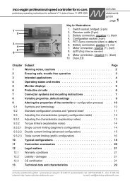
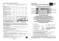
"One-Batt-Screen" mode<br />
22:17a8.50V 22:17a8.50V 4.7A<br />
4.7A<br />
nA1 A1 A1nL^de08.q0046<br />
A1 L^de08.q0046<br />
schulze elektronik gmbh • prenzlauer weg 6 • D-64331 weiterstadt • tel: 06150/1306-5, fax: 1306-99<br />
internet: http://www.schulze-elektronik.com e-mail: mail@schulze-elektronik.com<br />
Ch. time<br />
Batt1 code:<br />
"Onebattfullscreen"<br />
"full" probability<br />
Battery<br />
voltage<br />
Linear ch.<br />
Peak termination<br />
delayed by 8 minutes<br />
"Two-Batt-Screen" mode<br />
Line 1 = Battery 1<br />
Line 2 = Battery 2<br />
Pulsed ch.<br />
Temperaturetermination<br />
Pl. holder for<br />
7 00 start time<br />
symbol<br />
A1P°ready A1P°ready I=6.0A<br />
I=6.0A<br />
08:55 08:55 9.19V#3.0A<br />
9.19V#3.0A<br />
Ch. time Battery<br />
voltage<br />
Ch. current<br />
Ch. quantity<br />
in mAh, after<br />
10 Ah in Ah.<br />
q stands for<br />
"Quantity"<br />
Fixed current<br />
charge program<br />
Charge current<br />
"Reduced" symbol, since<br />
primary current set to 9 A<br />
Indirect displays: Batt. 2 set to peak term., as battery 1 is set to temp. termination.<br />
Batt. 2 is on pulsed charge, as battery 1 is set to pulsed charge.
<strong>ecolader</strong>: <strong>rapid</strong> <strong>dis<strong>charger</strong></strong>/<strong>charger</strong> <strong>series</strong><br />
Operating instructions for software V1.04, date of issue 05 MAY 1998<br />
8.10 Termination check count<br />
Description:<br />
This function is used to configure the automatic<br />
charge termination system.<br />
Checks on the probability of the battery being<br />
fully charged are made at 30-second intervals<br />
after the first peak is detected.<br />
The battery is only considered to be full<br />
when the test result is positive over the desired<br />
number of checks, and the charge current<br />
is then switched off. This means that<br />
brief variations in battery voltage due to cell<br />
"noise" or other effects do not result in premature<br />
charge termination.<br />
Note that too many checks prolong the test<br />
period and allow the battery to heat up more<br />
than is necessary.<br />
Activating the menu point:<br />
Press the akku x button<br />
Select value:<br />
Press the + or - button<br />
Value range:<br />
2 x ... 3 x ... 7 x (at approx. 30 s intervals)<br />
Confirm value:<br />
Press enter<br />
Interrupt:<br />
Press esc<br />
Caution:<br />
Do not change this parameter unless you<br />
understand exactly how the system works!<br />
Notes:<br />
The number of termination checks works<br />
hand in hand with charge termination sensitivity<br />
and the fixed check time interval.<br />
Three checks with a sensitivity of 3 mV /<br />
cell, using a 6-cell pack and a test period of<br />
about 90 seconds, produce a minimum<br />
voltage drop of:<br />
3 mV * 6 cells * 3 checks = 54 mV<br />
The actual voltage drop is usually higher<br />
(100-400mV).<br />
If the batteries are too hot after the charge<br />
termination, you should reduce the number of<br />
checks to 2 (e.g. if you are charging at more<br />
than 6 A). If they are too cold, the number of<br />
checks can be increased to 7.<br />
When pulsed charging is in use, the charge<br />
is terminated after 5 checks at most.<br />
schulze<br />
elektronik<br />
gmbh<br />
Page 15<br />
8.11 Termination sensitivity<br />
Description:<br />
This function is used to configure the automatic<br />
charge termination system.<br />
The likelihood that a battery is fully charged<br />
varies according to the magnitude of the<br />
voltage drop after the peak. This voltage<br />
drop must be greater than the set sensitivity<br />
over the time period of about 30 seconds<br />
(fixed internal period) if the battery is to be<br />
recognised as fully charged.<br />
Caution:<br />
This parameter prevents erroneous premature<br />
terminations. It is not designed to charge<br />
a battery "fuller than full" by setting high values.<br />
Please see also Section 8.10.<br />
High values reduce the possibility of erroneous<br />
terminations, but may not be achieved by<br />
the battery under certain circumstances due<br />
to low charge currents (owing to the automatic<br />
current calculation system towards the end<br />
of the charge) with the possible result that the<br />
battery could be overcharged.<br />
The sensitivity value you enter refers to a<br />
single cell, i.e. a 6-cell pack will exhibit six<br />
times the value. This value is calculated by<br />
the automatic charge termination circuitry<br />
based on the calculated number of cells.<br />
Activating the menu point:<br />
Press the akku x button.<br />
Select value:<br />
Press the + or - button.<br />
Value range:<br />
batt. 1, 2: 0 mV ... 3 mV ... 5 mV (per cell).<br />
batt. 3: 0 mV ... 1 mV ... 5 mV (per cell).<br />
Confirm value:<br />
Press enter<br />
Interrupt:<br />
Press esc<br />
Notes:<br />
Hybrid cell batteries (Panasonic, yellow<br />
Sanyo) should be charged with the sensitivity<br />
reduced to 1 mV.<br />
Nickel Metal Hydride batteries should be<br />
charged with the sensitivity reduced to 0<br />
(zero), and a fixed current setting of about<br />
0.5 to 1 C.<br />
schulze elektronik gmbh • prenzlauer weg 6 • D-64331 weiterstadt • tel: 06150/1306-5, fax: 1306-99<br />
internet: http://www.schulze-elektronik.com e-mail: mail@schulze-elektronik.com
Page 16 <strong>ecolader</strong>: <strong>rapid</strong> <strong>dis<strong>charger</strong></strong>/<strong>charger</strong> <strong>series</strong><br />
8.12 Termination criteria<br />
Description:<br />
This function is used to define which criterion<br />
the <strong>ecolader</strong> is to use to detect the "battery<br />
full" condition<br />
The following criteria are available for you to<br />
select:<br />
Peak:<br />
Termination criterion is the voltage drop in<br />
the charge voltage which occurs with full<br />
cells due to temperature rise.<br />
Peak termination is also sometimes termed<br />
Delta-Peak termination.<br />
Peak and temperature:<br />
Termination criterion is the voltage drop in<br />
the charge voltage combined with cell temperature.<br />
This system only works if the temperature<br />
sensor is connected and a sensible<br />
termination temperature has been set (see<br />
Section 8.8).<br />
That criterion which first registers "battery<br />
full" effects the termination of the charge<br />
current.<br />
Continuous charge (no termination)<br />
For safety reasons the charge current is<br />
pre-set to 300 mA when you select continuous<br />
charging, although it is possible to increase<br />
it to a maximum of 500 mA.<br />
Temperature termination:<br />
This termination criterion is increased cell<br />
temperature.<br />
The function only works correctly if the temperature<br />
sensor is connected, and a sensible<br />
termination temperature has been set;<br />
the optimum temperature varies with the different<br />
methods of charging (see Sections<br />
8.8 and 8.13).<br />
Peak plus delay:<br />
Peak detection is only activated after the<br />
time set in Section 8.9 has elapsed.<br />
Peak plus delay and temperature:<br />
Peak detection is only activated after the<br />
time set in Section 8.9 has elapsed. The<br />
temperature monitoring is active from the<br />
start of the charge process.<br />
Activating the menu point:<br />
Press the akku x button.<br />
Select:<br />
Press the + or - button.<br />
Select range:<br />
As previously described.<br />
Confirm selection:<br />
Press enter<br />
Interrupt:<br />
Press esc<br />
Caution:<br />
Since the <strong>ecolader</strong> only has one temperature<br />
sensor socket, you should make certain that<br />
you have assigned the sensor to the correct<br />
battery: it makes no sense to activate temperature<br />
termination for Battery 1 and Battery 2 if<br />
both packs are to be charged simultaneously,<br />
as it is not possible to attach one sensor to<br />
both batteries at the same time.<br />
For this reason all other batteries are<br />
switched to peak detect termination if temperature<br />
termination is selected for one pack.<br />
Naturally, you can expect fatal results if the<br />
temperature sensor is connected to Battery 1,<br />
but temperature termination is activated for<br />
Battery 2.<br />
Special feature:<br />
Even when you activate pure temperature<br />
termination, the peak-detect system still<br />
works in the background.<br />
Should you happen to forget to attach the<br />
temperature sensor to the battery, the peak<br />
detect system will activate the buzzer to remind<br />
you of your error.<br />
When you carry out a Power-On-Reset, peak<br />
termination is always (additionally) activated<br />
for reasons of safety (i.e. sensor may not be<br />
attached to battery), and a continuous charge<br />
or a delay period will be switched off.<br />
Display:<br />
A "°" indicates that temperature termination<br />
is activated, and a "^" indicates peak detection.<br />
The criterion which has resulted in switching<br />
off the charge current is displayed on the far<br />
right of the screen after the charge:<br />
PEAK and TEMP refer here to the charge<br />
termination criteria.<br />
If after the charge you see QUANT or TIME,<br />
the charge process was interrupted prematurely<br />
because one of the safety limits was<br />
exceeded.<br />
schulze elektronik gmbh • prenzlauer weg 6 • D-64331 weiterstadt • tel: 06150/1306-5, fax: 1306-99<br />
internet: http://www.schulze-elektronik.com e-mail: mail@schulze-elektronik.com
<strong>ecolader</strong>: <strong>rapid</strong> <strong>dis<strong>charger</strong></strong>/<strong>charger</strong> <strong>series</strong><br />
Operating instructions for software V1.04, date of issue 05 MAY 1998<br />
8.13 Charge method<br />
Description:<br />
With this function you determine the method<br />
of charging to be used to charge your<br />
packs.<br />
The following methods are available:<br />
Linear charging:<br />
The most commonly used and straightforward<br />
of all methods of charging.<br />
The charge current stays constant for minutes<br />
at a time, and is only interrupted briefly<br />
for the automatic termination system to take<br />
measurements.<br />
If you charge a pack using automatic current<br />
calculation, you may find that a different<br />
charge current is applied after one of the<br />
short measurement pauses, but it will then<br />
be held constant again for a long period.<br />
Pulse charging:<br />
Pulse charging means that the charge current<br />
is divided up into pulses of current. After<br />
each pulse of charge current there follows<br />
a "rest" period in which no current<br />
flows.<br />
To avoid placing too severe a load on the<br />
mains PSU or car battery due to superimposed<br />
pulses, the charge pulses for Battery<br />
1 and Battery 2 are applied alternately.<br />
For this reason the pulsed current for Battery<br />
1 is 1.5 times the average charge current<br />
(soft pulses), and the pulsed current for<br />
Battery 2 is 3 times the average current<br />
(hard pulses).<br />
It is essential that your power supply can<br />
deliver these increased peak currents; this<br />
applies in particular to mains PSUs.<br />
For this reason, pulsed charging applies to<br />
Battery 1 and Battery 2 simultaneously.<br />
Example: Batt 1: 6 A --> 9 A pulsed current,<br />
Batt 2: 5 A --> 15 A pulsed current!<br />
Linear charging with refresh pulses:<br />
The charge process is interrupted at particular<br />
intervals by discharge pulses at the<br />
same rate as the charge current.<br />
Pulse charging with refresh pulses:<br />
The charge is interrupted at particular intervals<br />
by discharge pulses at the same rate<br />
as the pulsed charge current.<br />
schulze<br />
elektronik<br />
gmbh<br />
Page 17<br />
Refresh pulses can be set separately for Battery<br />
1 and Battery 2.<br />
Activating the menu point:<br />
Press the akku x button.<br />
Select:<br />
Press the + or - button.<br />
Select range:<br />
As described on the left.<br />
Confirm selection:<br />
Press enter<br />
Interrupt:<br />
Press esc<br />
Notes on refresh charging:<br />
The discharge pulses are intended to accelerate<br />
the regenerative effect of old batteries,<br />
and reduce the memory effect.<br />
An additional advantage is that the temperature<br />
rise sets in later as the packs approach<br />
the fully charged state. Batteries therefore<br />
stay cooler towards the end of the charge.<br />
During refresh charging you will hear quiet<br />
crackling noises from the battery; this is perfectly<br />
normal and is due to the high-current<br />
discharge pulses.<br />
Important note regarding refresh charging:<br />
It is important to take into account the delayed<br />
temperature rise in a battery by adjusting<br />
the temperature setting to lower values<br />
if you are using temperature charge termination.<br />
Display:<br />
The screen displays various symbols to indicate<br />
the charge method you have selected:<br />
"L" for Linear charging<br />
"P" for Pulse charging<br />
"f " for Refresh charging<br />
The symbols on the screen are slightly<br />
smaller than the usual symbol height, in order<br />
to be able to display the combination<br />
"Lf" and "Pf" in a single display field.<br />
"Two-Batt-Screen"<br />
Line 1 = Battery 1<br />
Line 2 = Battery 2<br />
Pulse charge<br />
Temperature<br />
termination<br />
A1P°ready A1P°ready auto auto C<br />
07:17 07:17 9.19V!3.5A<br />
9.19V!3.5A<br />
Ch. time Battery<br />
voltage<br />
Measure.<br />
pause<br />
Automatic<br />
ch. program<br />
Ch. current<br />
(before the<br />
meas. pause)<br />
Indirect displays: Batt. 2 set to peak termination, as Batt. 1 is set to temp. termin.<br />
Batt. 2 set to pulse charging, as Batt. 1 is being pulse-charged.<br />
schulze elektronik gmbh • prenzlauer weg 6 • D-64331 weiterstadt • tel: 06150/1306-5, fax: 1306-99<br />
internet: http://www.schulze-elektronik.com e-mail: mail@schulze-elektronik.com
Page 18 <strong>ecolader</strong>: <strong>rapid</strong> <strong>dis<strong>charger</strong></strong>/<strong>charger</strong> <strong>series</strong><br />
8.14 Charge current<br />
Description:<br />
This function is used to select the maximum<br />
possible charge current which the <strong>ecolader</strong><br />
is to apply when charging.<br />
Activating the menu point:<br />
Press the akku x button.<br />
Select value:<br />
Press the + or - button.<br />
Value range:<br />
Battery 1: 300 mA ... 6 A ... 10 A.<br />
Battery 2: 150 mA ... 4 A ... 5 A.<br />
Battery 3: 100 mA ... 1 A ... 2 A.<br />
Confirm value:<br />
Press enter<br />
Interrupt:<br />
Press esc<br />
Notes:<br />
The actual charge current may be lower<br />
than the value you have set, depending on<br />
the number of cells, the maximum total current<br />
drain (primary current) and - in particular<br />
- if automatic current calculation is in<br />
use.<br />
Altering the charge current during a charge<br />
process only becomes effective if the<br />
change cannot upset automatic (peak) termination.<br />
That means: if the screen is displaying<br />
a "full" probability symbol (a, b...;<br />
see below), the charge continues temporarily<br />
with an unchanged current.<br />
"One-batt-full-scrn" mode<br />
Ch. time<br />
Batt. 2 code:<br />
"One-batt-full-s"<br />
"full" probability<br />
Battery<br />
voltage<br />
22:17a8.50V 22:17a8.50V 4.7A<br />
4.7A<br />
nA2 A2 A2nL^.....q0046<br />
A2 L^.....q0046<br />
Linear ch.<br />
Pl.-holder for<br />
7<br />
Place-holder for<br />
temperature display etc.<br />
00 start-time-<br />
Peak termination<br />
symbol<br />
Ch. current<br />
Ch. quantity<br />
in mAh, over<br />
10 Ah in Ah.<br />
q stands for<br />
"Quantity"<br />
8.15 Charge/disch. program<br />
This funtion is used to determine the charge or<br />
discharge program which is to be used.<br />
Activating the menu point:<br />
Press the akku x button.<br />
Select:<br />
Press the + or - button.<br />
Select range:<br />
As described below.<br />
Confirm select:<br />
Press enter<br />
Interrupt:<br />
Press esc<br />
8.15.1 Sel.CD*<br />
Purpose:<br />
This program is designed for measuring<br />
packs of cells using a high discharge current.<br />
Sequence:<br />
Before the discharge process the battery is<br />
fully charged using the auto C program.<br />
After the "full" termination the unit waits<br />
about 5 minutes and then re-starts the<br />
auto C program.<br />
After the "full" termination the unit waits a<br />
further 5 minutes and then starts the auto C<br />
program a third time.<br />
The point of this procedure is to have all<br />
packs "brim-full", even if individual cell capacities<br />
are not identical.<br />
After the charge process the pack is discharged<br />
at high rate using the fix--D program.<br />
Note:<br />
For discharge currents above 10 A the external<br />
discharge load resistance must be<br />
connected.<br />
The standard settings for charge and discharge<br />
current and limiting still apply.<br />
Display:<br />
In the "wait" pauses the following message<br />
appears on the screen:<br />
WaitUntil>hh:mm; hh:mm = time of day.<br />
schulze elektronik gmbh • prenzlauer weg 6 • D-64331 weiterstadt • tel: 06150/1306-5, fax: 1306-99<br />
internet: http://www.schulze-elektronik.com e-mail: mail@schulze-elektronik.com
<strong>ecolader</strong>: <strong>rapid</strong> <strong>dis<strong>charger</strong></strong>/<strong>charger</strong> <strong>series</strong><br />
Operating instructions for software V1.04, date of issue 05 MAY 1998<br />
8.15.2 Auto C<br />
Purpose:<br />
Optimum program for charging batteries<br />
quickly and completely, with very few preconditions<br />
(see select criteria below).<br />
Description:<br />
The <strong>ecolader</strong> automatically calculates the<br />
ideal charge current to suit the battery.<br />
This it does by measuring the pack con-tinuously,<br />
and repeatedly adjusting the<br />
charge current to suit the pack's energy absorption<br />
capacity and/or the maximum capacity<br />
of the <strong>ecolader</strong>.<br />
Initially the unit charges at 300 mA for a<br />
brief period, then it raises the current; towards<br />
the end of the charge the current is<br />
reduced again.<br />
The program charges until it detects the<br />
"full" state, then switches to a trickle charge.<br />
The calculated charge current is reduced if<br />
the <strong>charger</strong> threatens to overheat or overload.<br />
Select criteria:<br />
As a rule the fully automatic "Auto C"<br />
charge program is the best choice for Ni-Cd<br />
packs.<br />
It is not necessary to have an accurate<br />
knowledge of the type of Ni-Cd sintered cell<br />
battery provided that the capacity is within<br />
the range 300 mAh to 5 Ah - the only preconditions<br />
are adequate cross-section of<br />
the charge cable (2.5 mm2 ), high-quality<br />
connectors and a pack consisting of soldered<br />
cells.<br />
If the calculated charge currents turn out too<br />
low due to poor battery condition, the time<br />
limit trips to restrict the length of the charge.<br />
For this reason it may make sense initially<br />
to use a fixed current program (eg. Fix2CD)<br />
with a charge rate of 0.5 C ... 1 C, until the<br />
pack has to some extent come "back to life".<br />
If the battery will not accept currents above<br />
1 C ... 2 C in automatic mode, then either it<br />
is not suitable for <strong>rapid</strong>-charging, or it has<br />
come to the end of its life - it's "had it".<br />
8.15.3 Fix C<br />
schulze<br />
elektronik<br />
gmbh<br />
Page 19<br />
Purpose<br />
If you know the permissible charge currents<br />
for your batteries, you can use a suitable<br />
charge program with a fixed, defined current.<br />
This allows you to carry out balancing<br />
charges, standard and <strong>rapid</strong> charges (low,<br />
moderate and high currents respectively)<br />
with the charge times you calculate - depending<br />
on the batteries' initial state of<br />
charge.<br />
Description<br />
The selected program immediately starts<br />
charging using the current you have selected.<br />
The charge current is maintained until<br />
the pack is recognised to be fully charged.<br />
The charge rate is only reduced if the selected<br />
current and the pack's rising voltage<br />
present a danger of the unit overheating or<br />
overloading.<br />
Select criterion:<br />
Especially with Ni-MH batteries manual current<br />
selection (0.5 C to max. 1 C) is always<br />
preferable, with the automatic charge termination<br />
set to "sensitive" (see Section 8.11).<br />
With a small number of cells and a high<br />
charge current you can make the task of the<br />
automatic termination circuit easier by selecting<br />
a fixed current program:<br />
With 8 Ni-Cd cells the charge current should<br />
be at least 1.5 C, with 6 cells 2 C and with 4<br />
cells more than 3 C, so that a detectable<br />
voltage peak can occur. Read the manufacturer's<br />
notes to check that the pack is approved<br />
for charging at these currents!<br />
A fixed current program is the only alternative<br />
if you are obliged to charge batteries using<br />
charge leads which are too thin, because<br />
in that case the automatic current calculation<br />
circuit cannot work correctly. The<br />
high resistance of the small cable cross-section<br />
would be interpreted as internal battery<br />
resistance, and this would cause the charge<br />
current to be lower than ideal.<br />
The same applies if the calculated charge<br />
currents in automatic mode turn out too low<br />
due to poor battery condition; in this case<br />
the time limiter will trip. In such cases balance<br />
the battery beforehand using a fixed<br />
current program.<br />
A fixed current program is also a good alternative<br />
when you wish to charge a pack of<br />
known capacity within a particular timespan.<br />
schulze elektronik gmbh • prenzlauer weg 6 • D-64331 weiterstadt • tel: 06150/1306-5, fax: 1306-99<br />
internet: http://www.schulze-elektronik.com e-mail: mail@schulze-elektronik.com
Page 20 <strong>ecolader</strong>: <strong>rapid</strong> <strong>dis<strong>charger</strong></strong>/<strong>charger</strong> <strong>series</strong><br />
8.15.4 Fix -D<br />
Purpose:<br />
Program designed to discharge a pack<br />
quickly to the pre-set final discharge voltage.<br />
Description:<br />
The <strong>ecolader</strong> checks whether the set maximum<br />
discharge current will exceed the permissible<br />
discharge power limit.<br />
If so, it reduces the discharge current to a<br />
permissible value, and superimposes a<br />
flashing asterisk on the LCD screen.<br />
If not, the <strong>ecolader</strong> discharges the pack using<br />
your chosen current.<br />
The program discharges down to the final<br />
discharge voltage at a constant current.<br />
After this the discharge process is halted.<br />
Notes:<br />
Please bear in mind that high discharge currents<br />
(around 2 C or higher) will cause the<br />
battery to heat up. Cool it if necessary.<br />
You can allow the <strong>ecolader</strong> to calculate the<br />
final discharge voltage automatically, or set<br />
a limit value instead (see Section 8.17).<br />
At high discharge currents, and - in particular<br />
- when packs are being discharged<br />
simultaneously at akku 1 and akku 2 outputs,<br />
the <strong>charger</strong> can get very hot. To avoid<br />
over- heating, the discharge current is reduced<br />
in two stages, at which time the "reduced"<br />
symbol ("*") appears on the screen.<br />
Even when cooled down the full current will<br />
not flow until at least one pack is completely<br />
discharged.<br />
8.15.5 Auto-D<br />
Purpose:<br />
Optimum program for <strong>rapid</strong>ly but gently discharging<br />
batteries completely down to the<br />
final discharge limit. Ideal for erasing the<br />
memory effect of Ni-Cd batteries, and/or<br />
preparatory to completely discharging them<br />
using individual resistances.<br />
Description:<br />
The <strong>ecolader</strong> checks whether the set maximum<br />
discharge current will exceed the permissible<br />
discharge power limit.<br />
If so, it reduces the discharge current to a<br />
permissible value, and superimposes a<br />
flashing asterisk ("*") on the LCD screen.<br />
If not, the <strong>ecolader</strong> discharges the pack using<br />
your chosen current.<br />
The program discharges down to the final<br />
discharge voltage at a constant current.<br />
After this the discharge current is reduced<br />
gradually so that the the voltage does not<br />
fall below the set final discharge voltage limit.<br />
When the discharge current falls to a fraction<br />
of the pre-set value, the discharge process<br />
is halted.<br />
Notes:<br />
Please bear in mind that high discharge currents<br />
(around 2 C or higher) will cause the<br />
battery to heat up. Cool it if necessary.<br />
You can allow the <strong>ecolader</strong> to calculate the<br />
final discharge voltage automatically, or set<br />
a limit value instead (see Section 8.17).<br />
At high discharge currents, and - in particular -<br />
when packs are being discharged simultaneously<br />
at akku 1 and akku 2 outputs, the<br />
<strong>charger</strong> can get very hot. To avoid overheating,<br />
the discharge current is reduced in<br />
two stages, at which time the "reduced"<br />
symbol ("*") appears on the screen. Even<br />
when cooled down the full current will not<br />
flow until at least one pack is completely discharged.<br />
schulze elektronik gmbh • prenzlauer weg 6 • D-64331 weiterstadt • tel: 06150/1306-5, fax: 1306-99<br />
internet: http://www.schulze-elektronik.com e-mail: mail@schulze-elektronik.com
<strong>ecolader</strong>: <strong>rapid</strong> <strong>dis<strong>charger</strong></strong>/<strong>charger</strong> <strong>series</strong><br />
Operating instructions for software V1.04, date of issue 05 MAY 1998<br />
8.15.6 Aut_DC, Fix_DC<br />
(_ = 1...8 and X)<br />
Purpose<br />
The battery care programs (1DC ... XDC)<br />
balance your batteries in order to erase any<br />
existing memory effect, or to force the<br />
chemistry to "get going". Those batteries in<br />
particular which are only slightly discharged<br />
(e.g. transmitter and receiver batteries),<br />
need to be discharged completely and then<br />
recharged on a regular basis. Irregularly<br />
maintained or brand-new packs often require<br />
this procedure to be repeated several<br />
times in sequence.<br />
Description<br />
The battery connected to the <strong>charger</strong> is discharged<br />
to the final discharge voltage using<br />
the xxxx-D program, and then recharged<br />
using the xxxx C program (repeated n times<br />
if you are using the xxx_DC program). The<br />
program continues charging until the peak is<br />
detected, then switches to a trickle charge.<br />
The initial value for the discharge current is<br />
calculated from the maximum discharge<br />
power and/or the maximum permissible discharge<br />
current for the <strong>ecolader</strong>.<br />
When the final discharge voltage is reached<br />
using one of the automatic programs, the<br />
discharge current is reduced until it reaches<br />
a low value.<br />
Continuous charge current adjustment relative<br />
to the pack's energy absorption capacity<br />
in the automatic programs.<br />
The calculated charge current is reduced if<br />
there is a danger that the unit will overheat<br />
or be overloaded.<br />
Select criteria:<br />
If the calculated charge currents turn out too<br />
low in automatic mode due to poor battery<br />
condition, the time limiter eventually trips.<br />
For this reason it may make sense to start<br />
by using a fixed current program (e.g.<br />
Fix2DC) and a current of 0.5 C ... 1 C until<br />
the battery has to some extent "come back<br />
to life".<br />
If the battery refuses to accept currents<br />
above 1 C ... 2 C in automatic mode, it is either<br />
unsuitable for <strong>rapid</strong>-charging, or it is approaching<br />
the end of its life; it's "had it".<br />
8.15.7 Aut_CD, Fix_CD<br />
(_ = 1...8 and X)<br />
schulze<br />
elektronik<br />
gmbh<br />
Page 21<br />
Purpose<br />
This program is ideal for studying the<br />
changing behaviour of individual battery<br />
packs. It provides a useful means of checking<br />
their usefulness based on varying capacity<br />
data.<br />
Description<br />
The battery connected to the <strong>charger</strong> is<br />
charged up using the xxxx C program, and<br />
then discharged again using the xxxx-D program.<br />
In the automatic programs the <strong>ecolader</strong> automatically<br />
and regularly calculates the optimum<br />
charge current for the battery.<br />
The calculated charge current is reduced if<br />
there is a danger that the unit will overheat<br />
or be overloaded. The program continues<br />
charging until the peak is detected.<br />
After this, the battery connected to the unit<br />
is discharged to the final discharge voltage.<br />
The initial value for the discharge current is<br />
calculated from the maximum discharge<br />
power and/or the maximum permissible discharge<br />
current for the <strong>ecolader</strong>.<br />
When the final discharge voltage is reached<br />
using one of the automatic programs, the<br />
discharge current is reduced until it reaches<br />
a low value.<br />
Select criteria:<br />
If the calculated charge currents turn out too<br />
low in automatic mode due to poor battery<br />
condition, the time limiter eventually trips.<br />
For this reason it may make sense to start<br />
by using a fixed current program (e.g.<br />
Fix2DC) and a current of 0.5 C ... 1 C until<br />
the battery has to some extent "come back<br />
to life".<br />
If the battery refuses to accept currents<br />
above 1 C ... 2 C in automatic mode, it is either<br />
unsuitable for <strong>rapid</strong>-charging, or it is approaching<br />
the end of its life; it's "had it".<br />
Important with all combination programs:<br />
These programs only function if you are<br />
using peak-detect or temperature termination.<br />
Exceeding a charge quantity or<br />
charge time causes the combination program<br />
to be halted.<br />
Setting the number of cycles: see Section 8.19<br />
schulze elektronik gmbh • prenzlauer weg 6 • D-64331 weiterstadt • tel: 06150/1306-5, fax: 1306-99<br />
internet: http://www.schulze-elektronik.com e-mail: mail@schulze-elektronik.com
Page 22 <strong>ecolader</strong>: <strong>rapid</strong> <strong>dis<strong>charger</strong></strong>/<strong>charger</strong> <strong>series</strong><br />
8.16 Discharge current<br />
Description:<br />
This function is used to select the maximum<br />
possible discharge current which the <strong>ecolader</strong><br />
is to use for discharging.<br />
Any current value above 10 A can be<br />
achieved using a separate discharge load resistance<br />
(accessory) plugged into the <strong>charger</strong>.<br />
The discharge load resistance is rated at<br />
0.40 Ohm, and is ideal for a standard 20 A<br />
discharge with a 6-cell pack. The resistance<br />
provides the basic load at the start of the<br />
discharge process, and the internal discharge<br />
current sink maintains a constant<br />
software-controlled 20 A discharge rate as<br />
battery voltage falls off.<br />
Activating the menu point:<br />
Press the akku x button.<br />
Select value:<br />
Press the + or - button.<br />
Value range:<br />
Battery 1: 300 mA ... 6 A ... 10 A ... 32 A.<br />
Battery 2: 150 mA ... 4 A ... 5 A.<br />
Battery 3: 100 mA ... 1 A ... 2 A.<br />
Confirm value:<br />
Press enter<br />
Interrupt:<br />
Press esc<br />
Note:<br />
The actual discharge current may be lower<br />
than the value set, depending on the number<br />
of cells.<br />
When the discharge load resistance is in<br />
use, the discharge current may be higher<br />
than the value set if the Ohm value of the<br />
discharge load resistance does not permit a<br />
lower current value. The minimum discharge<br />
current can be calculated from the formula:<br />
I = U / R. Example: a "pushed" 6-cell pack<br />
when freshly charged has a voltage under<br />
load of slightly less than 8 V. With our standard<br />
0.40 Ohm discharge load resistance<br />
this produces a minimum discharge current<br />
of: 7.8 V / 0.40 Ohm = 19.5 A.<br />
The <strong>ecolader</strong> software does not switch on<br />
the external discharge load resistance when<br />
battery voltage is above 10.5 V to guard<br />
against overload.<br />
8.17 Min. discharge voltage<br />
Description:<br />
This function is used to set the termination<br />
voltage of your battery during the discharge<br />
process.<br />
Activating the menu point:<br />
Press the akku x button<br />
Select value:<br />
Press the + or - button.<br />
Value range:<br />
automatic:<br />
The <strong>ecolader</strong> calculates the final discharge<br />
voltage from the number of cells in the pack<br />
and the discharge current in use.<br />
or:<br />
Battery 1, Battery 2: 500 mV ... 10 V<br />
Battery 3: 1 V ... 10 V<br />
in 500 mV increments<br />
Confirm value:<br />
Press enter<br />
Interrupt:<br />
Press esc<br />
Notes:<br />
If you are using the fixed limit values you<br />
may have to enter different limit values with<br />
different numbers of cells and different discharge<br />
currents.<br />
For a given number of cells, the automatic<br />
circuit sets the termination voltage lower the<br />
higher the discharge current is set. The<br />
baseline voltage for the calculation is 0.7 V/<br />
cell.<br />
In the automatic setting the calculated termination<br />
voltage can be read off during or<br />
after the discharge (and charge) process in<br />
the top line of the LCD screen when you call<br />
up the menu point.<br />
Connecting the discharge resistance and batteries<br />
schulze elektronik gmbh • prenzlauer weg 6 • D-64331 weiterstadt • tel: 06150/1306-5, fax: 1306-99<br />
internet: http://www.schulze-elektronik.com e-mail: mail@schulze-elektronik.com
<strong>ecolader</strong>: <strong>rapid</strong> <strong>dis<strong>charger</strong></strong>/<strong>charger</strong> <strong>series</strong><br />
Operating instructions for software V1.04, date of issue 05 MAY 1998<br />
8.18 Correcting the cell count<br />
Description:<br />
This function allows you to override the <strong>ecolader</strong>'s<br />
automatic cell count calculation. The<br />
number of cells, as calculated by the <strong>ecolader</strong><br />
automatically, or corrected manually<br />
by the operator, is transferred to the winsoft<br />
software and is used for battery analysis.<br />
Activating the menu point:<br />
Press the akku x button.<br />
Select value:<br />
Press the + or - button.<br />
Value range:<br />
1 cell ... 6 cells ... 8 cells<br />
Confirm value:<br />
Press enter<br />
Interrupt:<br />
Press esc<br />
Notes:<br />
The calculated cell count is used by the automatic<br />
charge termination system to determine<br />
the actual termination sensitivity, and<br />
to calculate automatically the final discharge<br />
voltage in the discharge process.<br />
It is true that a slight mis-calculation in the<br />
cell count makes it impossible to detect significant<br />
capacity differences during the discharge<br />
process, as the termination usually<br />
occurs in the steeply falling section of the<br />
voltage curve.<br />
In the case of deep-discharged cells the cell<br />
count is automatically corrected repeatedly<br />
in the last few minutes of the charge process.<br />
If you manually correct the cell count after<br />
connecting the battery to the <strong>charger</strong>, the<br />
unit will not make any further automatic corrections.<br />
schulze<br />
8.19 No. of cycles of<br />
combination program<br />
elektronik<br />
gmbh<br />
Page 23<br />
Purpose:<br />
Tired batteries have to be "got into training"<br />
by repeated charge / discharge cycles. If a<br />
pack is to be revived completely, the number<br />
of cycles should be set higher or lower depending<br />
on the age and condition of the pack.<br />
Description:<br />
This function is used to set the number of<br />
cycles the combination programs xxx_DC<br />
(see Section 8.15.6) and xxx_CD (see Section<br />
8.15.7) are to complete during their<br />
course. One cycle consists of two phases:<br />
first the charge, then the discharge, or first<br />
the discharge, then the charge phase.<br />
Special feature:<br />
The process of repeating the program "X"<br />
times is concluded when the <strong>charger</strong> determines<br />
no further rise in capacity during the<br />
discharge process. In any case it finishes<br />
after 9 cycles.<br />
Activating the menu point:<br />
Press the akku x button.<br />
Select:<br />
Press the + or - button.<br />
Select range:<br />
1 x ... 9 x (9 x = X times function)<br />
Confirm select:<br />
Press enter<br />
Interrupt:<br />
Press esc<br />
Notes:<br />
The xxx4DC program consists of 8 phases:<br />
4 discharge phases (1, 3, 5, 7) and 4 charge<br />
phases (2, 4, 6, 8). The <strong>ecolader</strong> select<br />
transfers the number of the phase to the<br />
comment segment of the winsoft software,<br />
where it appears as a title to the diagram.<br />
The number of the phase appears in brackets<br />
in the status display during the charge /<br />
discharge process. (hold the akku button<br />
pressed in for one second).<br />
If you are using a combination program the<br />
charge time limit or the charge quantity limit<br />
still apply - but for each phase separately!<br />
After all, a 2000 mAh pack can still only absorb<br />
2 Ah after three discharge / charge<br />
cycles, and not 6 Ah.<br />
schulze elektronik gmbh • prenzlauer weg 6 • D-64331 weiterstadt • tel: 06150/1306-5, fax: 1306-99<br />
internet: http://www.schulze-elektronik.com e-mail: mail@schulze-elektronik.com
Page 24 <strong>ecolader</strong>: <strong>rapid</strong> <strong>dis<strong>charger</strong></strong>/<strong>charger</strong> <strong>series</strong><br />
8.20 Program after Power-On<br />
Reset (POR)<br />
Description:<br />
This function is used to set your choice of<br />
default program, i.e. the program which is<br />
selected when you initially connect the <strong>ecolader</strong><br />
to the car battery.<br />
Activating the menu point:<br />
Press the akku x button.<br />
Select:<br />
Press the + or - button.<br />
Select range:<br />
All programs as described in Section 8.15.<br />
Default setting battery 1+2: Auto C<br />
Default setting battery 3: Fix C<br />
Confirm select:<br />
Press enter<br />
Interrupt:<br />
Press esc<br />
Special features:<br />
Menu point "last":<br />
If you choose "last" the <strong>charger</strong> will set the<br />
program which was last used, i.e. was in<br />
use before you disconnected it from the car<br />
battery), when you connect the unit to the<br />
car battery next time.<br />
"Sel.CD" program:<br />
This program is not available as a default<br />
after POR, and must be selected explicitly<br />
(see Section 8.15).<br />
8.21 Default values<br />
Description:<br />
This function allows you to enter settings for<br />
charging batteries and for using the <strong>ecolader</strong><br />
which you have found to be ideal for your<br />
purposes.<br />
Select:<br />
The settings are battery-specific, and are<br />
made using the three akku x buttons and<br />
the spezial button.<br />
battery 1:<br />
Max. charge time 50 min<br />
Max. charge quantity 3000 mAh<br />
Termination temperature 45° C<br />
Termination delay 8 min<br />
Termination check count 3 x<br />
Termination sensitivity 3 mV/cell<br />
Termination criterion Peak<br />
Charge method Linear charge<br />
Max. charge current 6 A<br />
Charge / discharge program Auto C<br />
Max. discharge current 6 A<br />
Final discharge voltage automatic<br />
Cycle count of combination program 1<br />
Program after POR Auto C<br />
battery 2:<br />
Max. charge time 50 min<br />
Max. charge quantity 3000 mAh<br />
Termination temperature 45° C<br />
Termination delay 8 min<br />
Termination check count 3 x<br />
Termination sensitivity 3 mV/cell<br />
Termination criterion Peak<br />
Method of charging Linear charge<br />
Max. charge current 4 A<br />
Charge / discharge program Auto C<br />
Max. discharge current 4 A<br />
Final discharge voltage automatic<br />
Cycle count of combination program 1<br />
Program after POR Auto C<br />
schulze elektronik gmbh • prenzlauer weg 6 • D-64331 weiterstadt • tel: 06150/1306-5, fax: 1306-99<br />
internet: http://www.schulze-elektronik.com e-mail: mail@schulze-elektronik.com
<strong>ecolader</strong>: <strong>rapid</strong> <strong>dis<strong>charger</strong></strong>/<strong>charger</strong> <strong>series</strong><br />
Operating instructions for software V1.04, date of issue 05 MAY 1998<br />
battery 3:<br />
Max. charge time 50 min<br />
Max. charge quantity 1000 mAh<br />
Termination temperature 45° C<br />
Termination delay 8 min<br />
Termination check count 3 x<br />
Termination sensitivity 1mV/cell<br />
Termination criterion Peak<br />
Charge method Linear charge<br />
Max. charge current 1 A<br />
Charge / discharge program Fix C<br />
Max. discharge current 1 A<br />
Final discharge voltage automatic<br />
Cycle count of combination program 1<br />
Program after POR Fix C<br />
special:<br />
Max. primary current 20 A<br />
Min. car battery voltage (Umin.) 11.2 V<br />
Light flashing<br />
Buzzer on<br />
LCD mode One-Batt-Screen<br />
Display / select default settings:<br />
Press enter to accept default setting<br />
(screen shows: "executed")<br />
Press esc to interrupt.<br />
8.22 Max. primary current<br />
schulze<br />
elektronik<br />
gmbh<br />
Page 25<br />
Description:<br />
This function avoids your car battery being overloaded<br />
(when the voltage falls to an unacceptable<br />
level); can also be used to prevent overloading<br />
a mains PSU.<br />
Mains PSUs may only be operated within their<br />
stated continuous load capacity (the lower value<br />
in the specification for the PSU) which is specific<br />
to that unit.<br />
If you ignore this, there is a danger that the<br />
mains PSU will overheat, or its output voltage will<br />
collapse under severe load. As a rule the <strong>ecolader</strong><br />
carries out a Reset in this situation, i.e. it<br />
acts as if it had just been connected to the car<br />
battery, and then "hangs" at the self-test stage<br />
since batteries are already connected to it.<br />
In the worst case the <strong>ecolader</strong> may "hang" at full<br />
charge current, and in this situation it is very likely<br />
to wreck your valuable batteries.<br />
You can avoid such a disaster by setting an input<br />
current (primary current) which suits your mains<br />
PSU, i.e. you limit the <strong>ecolader</strong>'s current drain.<br />
Bear in mind that the <strong>ecolader</strong> itself consumes a<br />
small idle current, and this must also be included<br />
in the calculation.<br />
Also remember that a limit placed on the primary<br />
current means that the full level of current pulses<br />
will not be achieved if you use pulsed charging.<br />
Method of working:<br />
If the permissible primary current is exceeded,<br />
the charge current is reduced to a lower value.<br />
If several batteries are connected to the unit, the<br />
current to all batteries is reduced equally.<br />
Any current reduction is only restored when you<br />
disconnect a battery.<br />
Any current reduction is not restored when a battery<br />
reaches the fully charged stage.<br />
The current does not change if a battery is at the<br />
"full detection" stage (a, b ... on the screen). If<br />
you connect a new battery at this stage, the battery<br />
<strong>charger</strong> ignores it initially!<br />
Activating the menu point<br />
Press the spezial button<br />
Select:<br />
Press the + or - button<br />
Select range:<br />
5 A ... 20 A ... 22 A<br />
Confirm select, or interrupt:<br />
Press enter or esc<br />
Note:<br />
A reduction in primary current manifests itself in<br />
particular when you select pulsed charging, as<br />
the unit then limits the peak current drain instead<br />
of the average current drain.<br />
schulze elektronik gmbh • prenzlauer weg 6 • D-64331 weiterstadt • tel: 06150/1306-5, fax: 1306-99<br />
internet: http://www.schulze-elektronik.com e-mail: mail@schulze-elektronik.com
Page 26 <strong>ecolader</strong>: <strong>rapid</strong> <strong>dis<strong>charger</strong></strong>/<strong>charger</strong> <strong>series</strong><br />
8.23 Car battery min. voltage<br />
Description:<br />
The purpose of this function is to avoid discharging<br />
your car battery excessively.<br />
Deep-discharging causes long-term damage<br />
to the battery, and could also mean that<br />
your car engine will not start at the end of<br />
the session.<br />
Activating the menu point:<br />
Press the spezial button.<br />
Select value:<br />
Press the + or - button.<br />
Value range:<br />
10.4 V ... 11.2 V ... 11.6 V<br />
in 100 mV increments<br />
Confirm value:<br />
Press enter<br />
Interrupt:<br />
Press esc<br />
Notes:<br />
The default value is preceded by an asterisk.<br />
The range of values stated above represents<br />
the voltage limit below which the <strong>ecolader</strong><br />
beeps at you slowly to draw your attention<br />
to the low battery voltage.<br />
If the battery voltage falls to more than 0.5<br />
V below the selected voltage, all charge and<br />
discharge processes are halted.<br />
Display:<br />
If the battery reaches the set low voltage<br />
limit the <strong>ecolader</strong> shows the following:<br />
Carbattvolts=MIN<br />
and beeps at 2-second intervals.<br />
If it falls by a further 0.5 V (500 mV) the<br />
screen shows the following message:<br />
Carbattvolts
<strong>ecolader</strong>: <strong>rapid</strong> <strong>dis<strong>charger</strong></strong>/<strong>charger</strong> <strong>series</strong><br />
Operating instructions for software V1.04, date of issue 05 MAY 1998<br />
8.25 Displaying the serial number<br />
of the <strong>charger</strong><br />
Description:<br />
The purpose of this function is to provide information<br />
only. For example, it allows the<br />
9 LCD monitor displays<br />
Method of charging:<br />
"L" Linear charge (L only 5 pixel high)<br />
"P" Pulsed charge (p only 5 pixel high)<br />
"f" Refresh charge (f only 5 pixel high)<br />
Termination criterion:<br />
"^" Peak termination activated<br />
"°" Temperature termination activated<br />
"45°M" Termination temperature (Max, at 'ready')<br />
"28°C" Sensor temperature (during charge)<br />
"A4.20V" Final discharge voltage (Automatic)<br />
"F4.50V" Final discharge voltage (Fixed volt.)<br />
Time symbol 700 Start at time<br />
_____ Place-holder (temp. or delay display)<br />
During charging or discharging:<br />
Time [Min. : Sec.] / [Hours h Min.]<br />
Voltage [Volts]<br />
Current [Amperes]<br />
After the time display:<br />
"a", "b"... "full" probability<br />
"f" (inverse, flashing) indicates "full"<br />
"e" (inverse, flashing) indicates "empty"<br />
"t" for trickle charge<br />
Before the current display:<br />
"!" Measurement pause during charge<br />
"*" reduced due to overheating danger<br />
""" reduced due to excess batt. voltage<br />
"," gradual reduction in "Auto-D"; final<br />
discharge voltage reached<br />
Professional selection unit for single cells (see Section 10.6)<br />
To compensate for the higher transfer<br />
resistance of the clip connection, four<br />
cells are each measured with two<br />
"zero-current" sensing connections.<br />
This is known as a 4-pole<br />
measurement.<br />
To achieve a 20 A discharge current,<br />
our discharge load resistance must be<br />
used with 0.30 Ohms.<br />
schulze<br />
elektronik<br />
gmbh<br />
Page 27<br />
software to determine which version of the<br />
circuit board is fitted, so that any special<br />
hardware features can be taken into account.<br />
"#" reduced due to primary current limit<br />
"
Page 28 <strong>ecolader</strong>: <strong>rapid</strong> <strong>dis<strong>charger</strong></strong>/<strong>charger</strong> <strong>series</strong><br />
10 Auxiliary sockets<br />
(pins on side of case)<br />
On both sides of the <strong>charger</strong>'s case you will find<br />
a double row of pins for the connection of<br />
auxiliary devices<br />
[*] <strong>ecolader</strong> select only<br />
10.1* Discharge load, left side of case<br />
The discharge load resistance is designed to<br />
allow discharge currents of more than 10 A;<br />
the internal current sink permits a maximum<br />
discharge current of no more than 10 A.<br />
The currents drawn by the external resistance<br />
vary with the voltage of the pack to be discharged.<br />
For this reason the internal discharge<br />
current sink is coupled with the external<br />
resistance for discharging. For example,<br />
it very accurately holds the total discharge<br />
current constant as battery voltage<br />
falls.<br />
The value of the external discharge resistance<br />
has been chosen to ensure that a 6-cell<br />
pack can be discharged at a constant rate<br />
of 20 A until it is completely flat.<br />
Since a fully charged 6-cell battery will<br />
cause a current of just on 20 A to flow<br />
through the external resistance, this represents<br />
the lowest discharge current for 6<br />
cells, even if you set 12 A or 15 A.<br />
The resistance should not be less than 0.40<br />
Ohm / 300 Watts for discharging 6 cells.<br />
The load resistance is always connected in parallel<br />
to the battery to be discharged, provided<br />
that you have set a discharge current<br />
higher than 10 A, and that a discharge program<br />
has been selected.<br />
Caution: standard commercial resistances will<br />
reach a temperature much higher than 100°<br />
C, and this presents a danger of fire or skin<br />
burns, and also of short-circuits if the resistance<br />
features exposed windings. For this<br />
reason use resistances with a case which<br />
prevents skin-contact, and which are either<br />
fitted with a cooling fan or can dissipate excess<br />
heat through a large-area ribbed heatsink<br />
(accessory).<br />
Connections: connect the 10-pin plug to the<br />
pins on the side, and connect the red banana<br />
plug to the positive socket of the akku<br />
1 charge socket (see photo on page 22).<br />
10.2 Flashing light output, left<br />
For connecting a 12 V / 25 W car flasher<br />
bulb to provide visual indication of a full or<br />
discharged battery.<br />
The active flasher output (and the buzzer) is<br />
switched off when you press any of the 9<br />
buttons on the <strong>charger</strong>.<br />
Max. load up to 12 V / 21 W (approx. 2 A).<br />
Circuit-breaker:<br />
The <strong>ecolader</strong> includes an electronic circuitbreaker<br />
which interrupts the lamp current in<br />
an overload situation. To reset the circuitbreaker<br />
disconnect the cable to the flashing<br />
light, and allow the circuit-breaker to cool off.<br />
Remove the cause of the overload before<br />
re-connecting it.<br />
10.3 Fan output, left<br />
For connecting a 12 V battery cooling fan.<br />
The output is polarised.<br />
It is connected permanently to the car battery<br />
supply, i.e. it is not switchable.<br />
Max. load 12 V / 5 W (approx. 0.4 A).<br />
The fan output is connected to the same circuit-breaker<br />
as the flasher output (see Section<br />
9.2).<br />
10.4 Temperature sensor, left (cal on eco+)<br />
For connecting the temperature sensor<br />
(LM335Z) supplied with the <strong>charger</strong>.<br />
10.5* PC socket, left<br />
For connecting to the serial (COM) interface<br />
of a compatible PC via the interface cable<br />
(with 9-pin sub-D connector) supplied.<br />
If your vacant serial port on the PC has a<br />
25-pin socket, use a 9 -> 25-pin mouse<br />
adaptor.<br />
See also Section 10: data interface.<br />
10.6* 8-channel 12-bit A/D converter, right<br />
For selecting individual cells it is important<br />
to obtain accurate voltage information on<br />
each separate cell in a pack when it is discharged<br />
at a high rate, preferably 20 A.<br />
This is possible with the <strong>ecolader</strong> select, as<br />
it provides a means of connecting 8 measurement<br />
wires to factory-assembled packs<br />
(up to 7 cells), and of producing the high<br />
discharge current using an external load resistance.<br />
schulze elektronik gmbh • prenzlauer weg 6 • D-64331 weiterstadt • tel: 06150/1306-5, fax: 1306-99<br />
internet: http://www.schulze-elektronik.com e-mail: mail@schulze-elektronik.com
<strong>ecolader</strong>: <strong>rapid</strong> <strong>dis<strong>charger</strong></strong>/<strong>charger</strong> <strong>series</strong><br />
Operating instructions for software V1.04, date of issue 05 MAY 1998<br />
Connections to saddle (“hump”) packs:<br />
An ideal method of connecting the individual<br />
measurement wires in the case of factorymade<br />
saddle packs is to use the small sockets<br />
which are designed to accept the discharge<br />
resistances for the individual cells.<br />
Alternatively you can make up a saddle<br />
pack discharge box precisely for this measurement<br />
task, by soldering a measurement<br />
cable to the pairs of contacts which are<br />
located over each cell connector.<br />
Caution: it only makes sense to use factory-assembled<br />
soldered packs for this purpose;<br />
the transfer resistances are too high<br />
for measuring individual cells.<br />
Connections to battery "sticks":<br />
If your stick packs are not fitted with discharge<br />
sockets, you can "make do" by soldering<br />
the measurement wires to pins, and<br />
slipping the pins under the heat-shrink<br />
sleeve.<br />
Single cells:<br />
Single cells should be clamped together in<br />
the form of sticks, fitting a plate (ideally consisting<br />
of woven copper cell link braid) between<br />
the cells. The measurement wires are<br />
soldered permanently to these plates.<br />
The cells can be supported in a U-shaped<br />
or V-shaped channel, for example. Even<br />
better, cut slots in a plastic tube to line up<br />
with the cell joints, fit the metal plates in the<br />
slots and press the cells together with a<br />
spring (see photos on page 30).<br />
Fitting the "sensor wires":<br />
If only one measurement wire is used between<br />
the cells to pick up the voltage, the<br />
contact from cell to cell must really be<br />
100%, otherwise any slight contact resistance<br />
will be assumed to be cell resistance,<br />
and the measurement will be incorrect. For<br />
4 cells you can use two wires per cell, which<br />
should be connected in the sequence<br />
shown in brackets (see page 27).<br />
Sequence of measurement wires:<br />
The order of the measurement wires should<br />
be coded using different colours, as it is essential<br />
to maintain the correct sequence, so<br />
that the PC analysis software (winsoft) can<br />
show the correct voltage for each cell in the<br />
pack.<br />
The colours of the wires are based on the colour<br />
code for electronic components which is<br />
in standard use throughout the world:<br />
schulze<br />
elektronik<br />
gmbh<br />
Page 29<br />
(exception: wire 7). 4 cells:<br />
0: black cell 1 - (cell 1 -)<br />
1: brown cell 1 + (cell 1 +)<br />
2: red cell 2 + (cell 3 -)<br />
3: orange cell 3 + (cell 3 +)<br />
4: yellow cell 4 + (cell 5 -)<br />
5: green cell 5 + (cell 5 +)<br />
6: blue cell 6 + (cell 7 -)<br />
7: white cell 7 + (cell 7 +)<br />
4-cell mode: cells 2, 4 and 6 absent.<br />
The black wire 0 must make very good contact<br />
with the pack as it carries the power supply<br />
to the 12-bit A/D converter.<br />
Wire No. 7 is a special case: between the black<br />
and white wires the voltage of the en-tire 7cell<br />
pack can be measured. The winsoft<br />
program assumes this to be the case.<br />
If you wish to measure batteries consisting of<br />
fewer cells, then this white wire must also<br />
be connected to the positive terminal of the<br />
last cell to transfer the overall voltage of the<br />
pack in every case.<br />
This even applies to packs of cells when you only<br />
wish to measure the overall voltage.<br />
With high-current charge processes in particular, the<br />
<strong>ecolader</strong> is not able to determine and display the<br />
exact voltage of a battery, due to the cable resistances<br />
inside and outside the <strong>charger</strong>. If you require<br />
exact voltage values, you must use the<br />
12-Bit measurement procedure. i. e. you<br />
should connect the black measurement wire to<br />
the negative terminal of the first cell in the pack,<br />
and the white wire to the last cell in the pack.<br />
If you use the 4-point measurement method<br />
(using the cell holder shown on page 27)<br />
you may find that “cells” 2, 4, and 6 exhibit a<br />
low voltage when the pack is on charge.<br />
These values are due to the transfer resistance<br />
of the clamp connection.<br />
To ensure that all measurement results are reliable<br />
and reproducible, the voltage data is<br />
not transferred via the 8 measurement wires<br />
if more than one battery is connected to the<br />
<strong>ecolader</strong> select.<br />
To avoid error messages (Voltage > MAX) when<br />
the sensor wires are connected, it is important<br />
when discharging or charging always to connect<br />
the negative terminal of the charge cable<br />
first, followed by the positive terminal,<br />
when the sensor wires are connected.<br />
You will obtain false measurements of the last<br />
cell in the pack if the battery is measured<br />
during a charge process and not, as is usual,<br />
during a discharge. The car battery /<br />
mains PSU voltage must not exceed 12 V.<br />
schulze elektronik gmbh • prenzlauer weg 6 • D-64331 weiterstadt • tel: 06150/1306-5, fax: 1306-99<br />
internet: http://www.schulze-elektronik.com e-mail: mail@schulze-elektronik.com
Page 30 <strong>ecolader</strong>: <strong>rapid</strong> <strong>dis<strong>charger</strong></strong>/<strong>charger</strong> <strong>series</strong><br />
11* Data interface<br />
The <strong>ecolader</strong> select transfers important charge<br />
and discharge data to the PC at one-second<br />
intervals when "on-line".<br />
To receive and analyse the data your PC must<br />
be loaded with our winsoft software, and<br />
the <strong>ecolader</strong> select must be connected to<br />
the PC using our interface cable (isl 8-<br />
RS232). Both are included with the <strong>ecolader</strong><br />
select.<br />
The following data is transferred:<br />
battery number,<br />
charge time in seconds,<br />
charge / discharge voltage in mV,<br />
charge / discharge current in mA,<br />
Temperature of the temperature sensor.<br />
If only Battery 1 is connected, the voltages are<br />
also transferred which are picked up by the<br />
8 measurement wires:<br />
Cell 1... cell 7 and the<br />
overall voltage of all the cells.<br />
The <strong>ecolader</strong> select also transfers a special set<br />
of incidental data at the start of the charge<br />
or discharge process, including the name of<br />
the program in use, date, time of day and<br />
cell count...<br />
The exact data format and pin-outs for the interface<br />
connector are shown in the Specification<br />
in Section 14.<br />
12* "winsoft" Windows®<br />
Software<br />
Using winsoft you can receive data from the<br />
<strong>ecolader</strong> select and the isl 8 (a <strong>charger</strong> /<br />
<strong>dis<strong>charger</strong></strong> for up to 36 cells, specially designed<br />
for model aircraft use), and store the<br />
information globally or selectively for each<br />
battery in files in the computer. You can<br />
then read in the data again, display it in<br />
graphic form, compare graphs with each<br />
other on-screen, normalise voltages for the<br />
cell count, smoothe curves, select combination<br />
program curves from an on-line data<br />
file, display energy statements for batteries,<br />
print out graphs (in colour), and much more.<br />
It is also possible to export the data to a<br />
spreadsheet program for further processing.<br />
The Windows software runs on any computer<br />
using Microsoft DOS 6.22 and Microsoft<br />
Windows für Workgroups 3.11; it also usually<br />
runs correctly with the immediate predecessor<br />
versions.<br />
Installation instructions are included in the<br />
readme.txt file on the 3.5" diskette supplied<br />
with the <strong>charger</strong>.<br />
The operating instructions for our winsoft analysis<br />
program is integrated into the software's<br />
Help texts, which can also be printed<br />
out from within the program page by page.<br />
Home-made selection device for individual cells (see Section 10.6)<br />
to + Batt. 1 charge socket to - Batt. 2 charge socket<br />
Detail enlargement, + terminal<br />
Detail enlargement, - terminal<br />
schulze elektronik gmbh • prenzlauer weg 6 • D-64331 weiterstadt • tel: 06150/1306-5, fax: 1306-99<br />
internet: http://www.schulze-elektronik.com e-mail: mail@schulze-elektronik.com
<strong>ecolader</strong>: <strong>rapid</strong> <strong>dis<strong>charger</strong></strong>/<strong>charger</strong> <strong>series</strong><br />
Operating instructions for software V1.04, date of issue 05 MAY 1998<br />
13 Legal matters<br />
13.1 Warranty<br />
All <strong>ecolader</strong> <strong>charger</strong>s are carefully checked<br />
and tested before dispatch.<br />
If you have a complaint, send the unit back to<br />
us with a clear description of the fault. A<br />
message such as "doesn't work properly" or<br />
"software error" doesn't help us much!<br />
Before you send your <strong>ecolader</strong> back to us,<br />
please test the unit carefully, as it costs us<br />
money to test a <strong>charger</strong>, and if it turns out to<br />
be in working order we have to recover<br />
those costs from you. In this case it makes<br />
no difference whether the fully functional<br />
<strong>charger</strong> is returned within the warranty period<br />
or not. Approved warranty claims are<br />
processed in accordance with our currently<br />
valid General Conditions of Business, which<br />
are printed in our catalogue.<br />
One further note: if a problem arises with any<br />
schulze product, send it directly to us without<br />
interfering with it in any way.<br />
This ensures that we can repair the unit quickly,<br />
pick up warranty faults without any dispute,<br />
and keep costs to a minimum.<br />
You can also be sure that we will fit genuine replacement<br />
parts which will work properly in<br />
your unit. Unfortunately we have had bad<br />
experience with third-party Service Centres<br />
which claim technical competence. Note<br />
also that any out-side interference with our<br />
products invalidates the warranty. Incompetent<br />
attempts at repair can cause further<br />
damage. We often find it impossible to estimate<br />
the repair cost of devices in such condition,<br />
and in certain circumstances we are<br />
then obliged to decline to repair it altogether.<br />
13.2 Limited liability / compensation<br />
We at <strong>Schulze</strong> <strong>Elektronik</strong> <strong>GmbH</strong> are unable to<br />
monitor the observance of our assembly<br />
and operation instructions, our prescribed<br />
conditions and methods for installation, connection,<br />
usage and maintenance of our battery<br />
<strong>charger</strong>s. For this reason we cannot accept<br />
liability for loss, damage or costs which<br />
arise through the inappropriate use of our<br />
schulze<br />
elektronik<br />
gmbh<br />
Page 31<br />
products, or are connected in any way with<br />
such use.<br />
Within the normal legal limits, our obligation to<br />
provide compensation, for whatever legal<br />
reason, is limited to the invoice value of that<br />
quantity of product immediately involved in<br />
the event which caused the damage. This<br />
does not apply if we are obliged to accept<br />
unlimited liability in accordance with mandatory<br />
law due to our deliberate or serious<br />
negligence.<br />
13.3 CE approval<br />
All <strong>ecolader</strong> units satisfy all relevant and mandatory<br />
EC directives: these are the EMF directives<br />
- 89/336/EWG,<br />
- 91/263/EWG and<br />
- 92/31/EWG.<br />
The product has been tested to meet the following<br />
basic technical standards:<br />
Interference radiation: EN 50 081-1:1992,<br />
Interference susceptibility: EN 50 082-1:1992<br />
and/or EN 50 082-2:1995.<br />
You are the owner of a product whose design<br />
and construction fulfil the safety aims of the<br />
EC for the safe operation of devices.<br />
The approval procedure includes a test of interference<br />
radiation, i.e. of interference generated<br />
by the <strong>charger</strong>. This <strong>charger</strong> has<br />
been tested under practical conditions at<br />
maximum load current and with the mostly<br />
used number of cells, and remains within<br />
the interference limits.<br />
The procedure also includes a test of interference<br />
susceptibility, i.e. the extent to which<br />
the <strong>charger</strong> is vulnerable to interference<br />
from other devices. The test involves subjecting<br />
the <strong>charger</strong> to RF signals similar to<br />
those produced by an RC transmitter or a<br />
radio telephone.<br />
Note:<br />
If you encounter problems in using this device,<br />
please carry out the measures described in<br />
Chapter 16 before you decide that it is defective.<br />
schulze elektronik gmbh • prenzlauer weg 6 • D-64331 weiterstadt • tel: 06150/1306-5, fax: 1306-99<br />
internet: http://www.schulze-elektronik.com e-mail: mail@schulze-elektronik.com
Page 32 <strong>ecolader</strong>: <strong>rapid</strong> <strong>dis<strong>charger</strong></strong>/<strong>charger</strong> <strong>series</strong><br />
14.1 Specification<br />
all models Weight Size Screen Screen<br />
approx. [kg] approx. [mm] [line x char] [area]<br />
1.1 207 x 142 x 58 2 x 16 61x15mm<br />
akku 1 akku 2 akku 3<br />
No. of cells (1-71 ) 4 - 7 (1-71 ) 4 - 7 (1-81 ) 4 - 8<br />
Charge / discharge currents 0.3 - 10 A 0.15 - 5 A 0.1 - 2 A<br />
Charge / discharge power max. 60 W 32 W 24 W<br />
for cell capacity<br />
Tolerances, <strong>ecolader</strong> +<br />
0.3 - 5 Ah 0.15 - 2.5 Ah 0.1-1 Ah<br />
Current, Batt. 1 & 2: typ. 5%; max. 15% or 250 mA (whichever is the greater)<br />
Current, Batt. 3: typ. 5%; max. 10% or 100 mA (whichever is the greater)<br />
Voltage: typ. 5%, max .10%<br />
Tolerances, <strong>ecolader</strong> select<br />
Current, Batt. 1 & 2: typ. 3%; max. 5% or 200 mA (whichever is the greater)<br />
Current, Batt. 3: typ. 5%; max. 10% or 100 mA (whichever is the greater)<br />
Voltage: typ. 3%, max. 5%<br />
12-bit ADC: typ. 1%, max. 3%<br />
Miscellaneous information:<br />
[ 1 ] All charge outputs can be used with 1 cell or more provided that the charge current is at least<br />
3 C and temperature monitoring is used for charging. Peak detection is too unreliable in such<br />
cases.<br />
- Total power dissipation of > 60 W can result in system shut-down due to overheating.<br />
- No-load current drain: approx. 200 mA<br />
- Power supply: 11 - 15.2 V<br />
- All data assumes a car battery voltage of 12 V ... 13.8 V DC<br />
- Recommended car battery: 12 V / 36 Ah or larger; must be fully charged to charge 7 cells!<br />
- Recommended mains PSU: 13.8V (required to charge 7 cells), ideally switchable to 12 V (recommended<br />
for charging 6 cells, as the <strong>ecolader</strong> stays cooler; current: 20/22 A.<br />
14.2 Other features<br />
- fully automatic charge current calculation, patent applied for<br />
- All battery outputs can be used simultaneously<br />
- All battery outputs suitable for Ni-Cd and Ni-MH batteries<br />
- Safety charge termination after selectable charge times<br />
- Safety charge termination according to selectable charge quantity<br />
- Safety charge termination according to selectable temperature (selectable battery output)<br />
- Low voltage warning, selectable within the range 10.4 - 11.6 V<br />
- Low voltage shut-down at 0.5 V below warning threshold<br />
- Electronic circuit-breaker in the + 12 V line for external connections<br />
<strong>ecolader</strong> select:<br />
- Precision 8-channel 12-bit analogue-digital converter provides selection facility for individual<br />
battery cells<br />
- Socket for external discharge load resistances (for 6-cell batteries preferably 0.40 Ohm, 300 W)<br />
14.3 Default settings for battery programs and <strong>charger</strong><br />
See Section 8.21; the default values are also underlined in the value ranges stated in the sub-sections<br />
of Section 8.<br />
schulze elektronik gmbh • prenzlauer weg 6 • D-64331 weiterstadt • tel: 06150/1306-5, fax: 1306-99<br />
internet: http://www.schulze-elektronik.com e-mail: mail@schulze-elektronik.com
<strong>ecolader</strong>: <strong>rapid</strong> <strong>dis<strong>charger</strong></strong>/<strong>charger</strong> <strong>series</strong><br />
Operating instructions for software V1.04, date of issue 05 MAY 1998<br />
14.4 Pin-outs of auxiliary sockets, seen from solder side of sockets<br />
Socket polarity<br />
schulze<br />
elektronik<br />
gmbh<br />
Page 33<br />
- - - - - + - + x - S R x Jumper, do not remove (Note: S,R,T = cal. output)<br />
- - - - - + - + - + T - Code connector, one pin absent, blind pin<br />
must be fitted in the socket<br />
(+,- = temp. sensor input)<br />
Disch. load* Flasher Fan Temp.Sensor/cal. Apply solder bridge to socket<br />
14.5* Pin-outs of PC interface, seen from solder side of socket<br />
T Gnd RS-232 interface SUB D socket 9-pin (25-pin)<br />
T = Transmit; connect to RXD Pin 2 (Pin 3)<br />
R = Receive; connect to TXD Pin 3 (Pin 2)<br />
R Gnd Signal GND; connect to GND Pin 5 (Pin 7)<br />
X = Code connector, one pin absent. Blind pin fitted in matching socket on RS-232 cable.<br />
14.6* Pin-outs of 8-channel ADC, seen from solder side of socket<br />
K 2+4+6+ x K = Calibration voltage output, not used when measuring batteries.<br />
1- = Negative terminal of whole battery pack (first cell)<br />
7+ = Positive terminal of whole battery pack (last cell)<br />
1-1+3+5+7+ 1+ ... 7+ = Voltage pick-ups at cell positive terminals. Keep to correct sequence of wires.<br />
X = Code connector, one pin absent. Blind pin in matching socket on sensor cable.<br />
14.7* Data format, PC interface<br />
Transmission speed: 9600 Baud<br />
Data set in ASCII: A:sssss:uuuuu:iiiiiVSttt##<br />
<strong>ecolader</strong> select 2 ;U1;U2;U3;U4;U5;U6;U7;Ug;<br />
Legend: A Battery No.<br />
sssss Time in seconds<br />
uuuuu Battery voltage in Millivolts<br />
iiiii Current in Milliamperes<br />
V[:,-] Current prefix<br />
S[l,L,E,t...] Charge / discharge status<br />
ttt[-, ,0..9] Temperature<br />
U1...7 12-bit cell voltage, 1-7 in mV 2<br />
Ug 12-bit overall voltage, U1...U7 in mV 2<br />
: or ; Data separator<br />
Comment set: *, Date, Day, Time, data source, battery No.,<br />
program in use, current combination program phase,<br />
charge method in use, charge termination criterion,<br />
Cell count 3<br />
[ 2 ] only if Akku 1 is in use alone<br />
[ 3 ] calculated cell count, which may be corrected automatically by the <strong>charger</strong> within the first 10 minutes<br />
of the charge process. Left unchanged if manually corrected.<br />
schulze elektronik gmbh • prenzlauer weg 6 • D-64331 weiterstadt • tel: 06150/1306-5, fax: 1306-99<br />
internet: http://www.schulze-elektronik.com e-mail: mail@schulze-elektronik.com
Page 34 <strong>ecolader</strong>: <strong>rapid</strong> <strong>dis<strong>charger</strong></strong>/<strong>charger</strong> <strong>series</strong><br />
15 Error messages and their causes<br />
If a limit value is exceeded (car battery voltage, <strong>charger</strong> temperature, maximum charge power), this<br />
results in some cases in interruption of the charge process (e.g. low car battery voltage), in others<br />
to a display of the cause of the error, and in others to the buzzer sounding; the buzzer is switched<br />
off automatically after a while.<br />
- After an error message only the charge quantity is displayed; the charge time and charge voltage<br />
can no longer be read off.<br />
- After an error message you must disconnect the <strong>ecolader</strong> from the battery voltage in order to reset<br />
the unit to the normal working state.<br />
- At Akku 3: if a battery voltage of less than about 0.5 V is detected, the <strong>charger</strong> assumes incorrect<br />
polarity.<br />
Error: Disconnect Disconnect Batt2/3! Batt2/3! and/or -Power-On-Reset-<br />
-Power-On-Reset-:<br />
-Power-On-Reset-<br />
Cause:<br />
a) Battery or batteries were connected to the <strong>charger</strong> before it was connected to the power supply.<br />
b) During a process the power from the car battery or mains PSU was interrupted, and was then<br />
switched on again (as a)).<br />
c) The "watchdog" circuit has tripped in the middle of a charge or discharge process. It trips when the<br />
micro-processor is brought to an unforeseen state, typically as a result of external interference.<br />
Note: This is not an error. The <strong>charger</strong> is not capable of deciding whether a charge program or a<br />
discharge program should be used, whether a combination program is required or whether it<br />
should start from the beginning again, or even whether it would be harmful to charge an already<br />
fully charg-ed pack at the set current.<br />
- For technical reasons no error message is produced if one or more batteries are connected to the<br />
<strong>charger</strong>, but the <strong>charger</strong> is not connected to its power supply.<br />
Error -# Cause of error<br />
B.1 B.2 B.3 battery-related<br />
- - 359 Converter voltage < min.<br />
- - 377 Converter power > max.<br />
- - - Batt. voltage > car battery voltage<br />
161 261 361 Linear charge current > max.<br />
162 262 - Pulse charge current > max.<br />
164 264 364 Discharge current > max<br />
166 - - Internal disch. current > max.<br />
168 - - External disch. current > max.<br />
175 275 375 Power dissipation of linear charge<br />
power source > max.<br />
176 276 - Power dissipation of pulsed<br />
charge current > maximum<br />
178 278 378 Power dissipation of discharge<br />
current sink > maximum<br />
Device-related error<br />
Error-# Cause of error<br />
961 Charger current > maximum<br />
(Primary current drain greater than set)<br />
962 Charger current > maximum<br />
(Current measurement via polarity<br />
guard greater than permitted)<br />
962 External discharge current > maximum.<br />
981 Charger temperature > maximum<br />
983 Battery temperature higher than 65° C<br />
904 Car battery voltage below minimum<br />
5 Car battery voltage at minimum<br />
(warning)<br />
906 Car battery voltage above maximum<br />
9 Auxiliary connector circuit-breaker<br />
overloaded (warning)<br />
99 Temperature sensor not connected<br />
schulze elektronik gmbh • prenzlauer weg 6 • D-64331 weiterstadt • tel: 06150/1306-5, fax: 1306-99<br />
internet: http://www.schulze-elektronik.com e-mail: mail@schulze-elektronik.com
<strong>ecolader</strong>: <strong>rapid</strong> <strong>dis<strong>charger</strong></strong>/<strong>charger</strong> <strong>series</strong><br />
Operating instructions for software V1.04, date of issue 05 MAY 1998<br />
16 Fault-finding, fault correction<br />
schulze<br />
elektronik<br />
gmbh<br />
Page 35<br />
Dear customer,<br />
If your battery <strong>charger</strong> does not appear to work as you expect it to, please run through the<br />
meas-ures described below one by one.<br />
If - and only if - you observe all these points, and the problem still persists, telephone us on<br />
Tuesday or Thursday for technical assistance. Even better, fill in the service questionnaire (on the<br />
next page) and send or fax it to us. We will then ring you back with our advice.<br />
From our many years' experience with battery <strong>charger</strong>s we know that most errors and<br />
faults can be avoided from the outset if you observe the measures outlined below.<br />
If you send your <strong>charger</strong> to us and we find no defect - a situation which in most cases involves<br />
one or other of the causes described below - we are obliged to point out to you that<br />
we charge for our time in checking equipment that is found to be in perfect working order,<br />
even if the unit is still under warranty.<br />
1. Connect the <strong>charger</strong> to a fully charged car battery of at least 36 Ah capacity. Don't use a<br />
mains-powered PSU!<br />
2. Be sure to use the original power cable to the power supply (with the original 4mm gold plated<br />
plugs), and at the car battery soldered 4mm sockets. Other types of connector, such as cheap banana<br />
plugs, car cigar lighter plugs etc. ... are not suitable! If you have made changes, kindly restore the original<br />
equipment. Soldered joints must be really sound - don't be satisfied with a bodged job.<br />
3. The charge cables for all batteries should consist of 2.5 sq mm cross-section conductors. The<br />
<strong>charger</strong>'s automatic current setting circuit is only able to set the ideal (high) charge current for your<br />
battery if it is using this heavy cable. You will be doing the charge termination circuit a real favour!<br />
4. Just as important as the charge cables are the connectors attached to them. At the <strong>charger</strong><br />
end please use 4 mm gold-contact connectors which have proved excellent in practice. Don't use<br />
expen-sive multi-contact plugs; in any case matching gold-contact connectors should also be fitted<br />
to your drive batteries and flight packs. Tin-plated connectors are simply not suitable as their contact<br />
resis-tance is high and they tend to produce intermittent contact in the long-term.<br />
5. Provided that you adhere to the measures outlined under points 3) and 4) above, the fully automatic<br />
charge setting circuit should produce a charge current of at least 1 C and usually more than<br />
2 C after about 5-10 minutes of charging a discharged pack. If this is not the case, then most likely<br />
the internal resistance of your battery is too high. Your battery has "had it", or is not suitable for <strong>rapid</strong>-charg-ing.<br />
6. Ensure that your battery pack contains no "dud" cells. When on charge any faulty cells usually<br />
heat up early, and then cause the automatic charge termination circuit to trip prematurely, and/or<br />
produce an excessively low charge current in automatic mode.<br />
7. If you charge a pack at the Akku 1 or Akku 2 output using an automatic program, and the<br />
charge time is longer than three hours, then something is wrong with your charge cable, your connectors<br />
or your battery - perhaps too small a charge lead conductor cross-section? Or no high-quality<br />
gold-contact connectors? Maybe your battery is ripe for retirement, or is not suitable for <strong>rapid</strong>charg-ing<br />
at all.<br />
Establish the cause! Raising the maximum charge time limit is not the right route to take; in fact, if<br />
your charge times are close to one hour this usually indicates that something is less than ideal. The<br />
automatic current calculation circuit should set a charge current of 1 C after just 5-10 minutes!<br />
8. Have you also read and observed the information in Section 1 (Warnings) and 2 (How to obtain<br />
reliable, trouble-free operation)?<br />
schulze elektronik gmbh • prenzlauer weg 6 • D-64331 weiterstadt • tel: 06150/1306-5, fax: 1306-99<br />
internet: http://www.schulze-elektronik.com e-mail: mail@schulze-elektronik.com
Page 36 <strong>ecolader</strong>: <strong>rapid</strong> <strong>dis<strong>charger</strong></strong>/<strong>charger</strong> <strong>series</strong><br />
17 Service questionnaire Your address:<br />
To: schulze elektronik gmbh and<br />
Fax-No. [0049] 6151 / 1306-99 Telephone number:<br />
Please enter the appropriate information in every single box!<br />
If the unit is defective, please return this form with the unit<br />
Battery: Your data: Example:<br />
Application (transmitter, receiver, drive battery) Flight pack<br />
Manufacturer Sanyo<br />
Cell count / Voltage 8 / 9.6 V<br />
Capacity 1700 mAh<br />
Type 1700SCE<br />
Cell connections soldered or clamped soldered<br />
Charge cable connector 4 mm gold<br />
Charge cable: Original <br />
Length 1.5 m<br />
Cross-section 0.14 sq mm<br />
Charger connector<br />
Power supply:<br />
Multi-contact<br />
Fault when using mains PSU yes<br />
PSU type Power 150<br />
Output voltage 13 V<br />
Output current 11 A<br />
Fault when using car battery: no<br />
Nominal capacity of car battery<br />
Charger:<br />
45 Ah<br />
Type <strong>ecolader</strong> +<br />
Charge output used Akku 1<br />
Selected charge program Auto C<br />
(Automatic mode:) max. charge current 0.83 A<br />
(Autom. mode:) Charge curr. at/before fault 0.25 A<br />
Duration of charge 133 min<br />
Battery temperature at charge termination 30°C<br />
Error message<br />
Description of fault:<br />
# 161<br />
○ ○ ○ ○ ○ ○ ○ ○ ○ ○ ○ ○ ○ ○ ○ ○ ○ ○ ○ ○ ○ ○ ○ ○ ○ ○ ○ ○ ○ ○ ○ ○ ○ ○ ○ ○ ○ ○ ○ ○ ○ ○ ○ ○ ○ ○ ○ ○ ○ ○ ○ ○ ○ ○ ○ ○ ○ ○ ○ ○ ○ ○<br />
○ ○ ○ ○ ○ ○ ○ ○ ○ ○ ○ ○ ○ ○ ○ ○ ○ ○ ○ ○ ○ ○ ○ ○ ○ ○ ○ ○ ○ ○ ○ ○ ○ ○ ○ ○ ○ ○ ○ ○ ○ ○ ○ ○ ○ ○ ○ ○ ○ ○ ○ ○ ○ ○ ○ ○ ○ ○ ○ ○ ○ ○<br />
○ ○ ○ ○ ○ ○ ○ ○ ○ ○ ○ ○ ○ ○ ○ ○ ○ ○ ○ ○ ○ ○ ○ ○ ○ ○ ○ ○ ○ ○ ○ ○ ○ ○ ○ ○ ○ ○ ○ ○ ○ ○ ○ ○ ○ ○ ○ ○ ○ ○ ○ ○ ○ ○ ○ ○ ○ ○ ○ ○ ○ ○<br />
○ ○ ○ ○ ○ ○ ○ ○ ○ ○ ○ ○ ○ ○ ○ ○ ○ ○ ○ ○ ○ ○ ○ ○ ○ ○ ○ ○ ○ ○ ○ ○ ○ ○ ○ ○ ○ ○ ○ ○ ○ ○ ○ ○ ○ ○ ○ ○ ○ ○ ○ ○ ○ ○ ○ ○ ○ ○ ○ ○ ○ ○<br />
○ ○ ○ ○ ○ ○ ○ ○ ○ ○ ○ ○ ○ ○ ○ ○ ○ ○ ○ ○ ○ ○ ○ ○ ○ ○ ○ ○ ○ ○ ○ ○ ○ ○ ○ ○ ○ ○ ○ ○ ○ ○ ○ ○ ○ ○ ○ ○ ○ ○ ○ ○ ○ ○ ○ ○ ○ ○ ○ ○ ○ ○<br />
○ ○ ○ ○ ○ ○ ○ ○ ○ ○ ○ ○ ○ ○ ○ ○ ○ ○ ○ ○ ○ ○ ○ ○ ○ ○ ○ ○ ○ ○ ○ ○ ○ ○ ○ ○ ○ ○ ○ ○ ○ ○ ○ ○ ○ ○ ○ ○ ○ ○ ○ ○ ○ ○ ○ ○ ○ ○ ○ ○ ○ ○<br />
○ ○ ○ ○ ○ ○ ○ ○ ○ ○ ○ ○ ○ ○ ○ ○ ○ ○ ○ ○ ○ ○ ○ ○ ○ ○ ○ ○ ○ ○ ○ ○ ○ ○ ○ ○ ○ ○ ○ ○ ○ ○ ○ ○ ○ ○ ○ ○ ○ ○ ○ ○ ○ ○ ○ ○ ○ ○ ○ ○ ○ ○<br />
○ ○ ○ ○ ○ ○ ○ ○ ○ ○ ○ ○ ○ ○ ○ ○ ○ ○ ○ ○ ○ ○ ○ ○ ○ ○ ○ ○ ○ ○ ○ ○ ○ ○ ○ ○ ○ ○ ○ ○ ○ ○ ○ ○ ○ ○ ○ ○ ○ ○ ○ ○ ○ ○ ○ ○ ○ ○ ○ ○ ○ ○<br />
○ ○ ○ ○ ○ ○ ○ ○ ○ ○ ○ ○ ○ ○ ○ ○ ○ ○ ○ ○ ○ ○ ○ ○ ○ ○ ○ ○ ○ ○ ○ ○ ○ ○ ○ ○ ○ ○ ○ ○ ○ ○ ○ ○ ○ ○ ○ ○ ○ ○ ○ ○ ○ ○ ○ ○ ○ ○ ○ ○ ○ ○<br />
○ ○ ○ ○ ○ ○ ○ ○ ○ ○ ○ ○ ○ ○ ○ ○ ○ ○ ○ ○ ○ ○ ○ ○ ○ ○ ○ ○ ○ ○ ○ ○ ○ ○ ○ ○ ○ ○ ○ ○ ○ ○ ○ ○ ○ ○ ○ ○ ○ ○ ○ ○ ○ ○ ○ ○ ○ ○ ○ ○ ○ ○<br />
○ ○ ○ ○ ○ ○ ○ ○ ○ ○ ○ ○ ○ ○ ○ ○ ○ ○ ○ ○ ○ ○ ○ ○ ○ ○ ○ ○ ○ ○ ○ ○ ○ ○ ○ ○ ○ ○ ○ ○ ○ ○ ○ ○ ○ ○ ○ ○ ○ ○ ○ ○ ○ ○ ○ ○ ○ ○ ○ ○ ○ ○<br />
○ ○ ○ ○ ○ ○ ○ ○ ○ ○ ○ ○ ○ ○ ○ ○ ○ ○ ○ ○ ○ ○ ○ ○ ○ ○ ○ ○ ○ ○ ○ ○ ○ ○ ○ ○ ○ ○ ○ ○ ○ ○ ○ ○ ○ ○ ○ ○ ○ ○ ○ ○ ○ ○ ○ ○ ○ ○ ○ ○ ○ ○<br />
○ ○ ○ ○ ○ ○ ○ ○ ○ ○ ○ ○ ○ ○ ○ ○ ○ ○ ○ ○ ○ ○ ○ ○ ○ ○ ○ ○ ○ ○ ○ ○ ○ ○ ○ ○ ○ ○ ○ ○ ○ ○ ○ ○ ○ ○ ○ ○ ○ ○ ○ ○ ○ ○ ○ ○ ○ ○ ○ ○ ○ ○<br />
○ ○ ○ ○ ○ ○ ○ ○ ○ ○ ○ ○ ○ ○ ○ ○ ○ ○ ○ ○ ○ ○ ○ ○ ○ ○ ○ ○ ○ ○ ○ ○ ○ ○ ○ ○ ○ ○ ○ ○ ○ ○ ○ ○ ○ ○ ○ ○ ○ ○ ○ ○ ○ ○ ○ ○ ○ ○ ○ ○ ○ ○<br />
○ ○ ○ ○ ○ ○ ○ ○ ○ ○ ○ ○ ○ ○ ○ ○ ○ ○ ○ ○ ○ ○ ○ ○ ○ ○ ○ ○ ○ ○ ○ ○ ○ ○ ○ ○ ○ ○ ○ ○ ○ ○ ○ ○ ○ ○ ○ ○ ○ ○ ○ ○ ○ ○ ○ ○ ○ ○ ○ ○ ○ ○<br />
○ ○ ○ ○ ○ ○ ○ ○ ○ ○ ○ ○ ○ ○ ○ ○ ○ ○ ○ ○ ○ ○ ○ ○ ○ ○ ○ ○ ○ ○ ○ ○ ○ ○ ○ ○ ○ ○ ○ ○ ○ ○ ○ ○ ○ ○ ○ ○ ○ ○ ○ ○ ○ ○ ○ ○ ○ ○ ○ ○ ○ ○<br />
○ ○ ○ ○ ○ ○ ○ ○ ○ ○ ○ ○ ○ ○ ○ ○ ○ ○ ○ ○ ○ ○ ○ ○ ○ ○ ○ ○ ○ ○ ○ ○ ○ ○ ○ ○ ○ ○ ○ ○ ○ ○ ○ ○ ○ ○ ○ ○ ○ ○ ○ ○ ○ ○ ○ ○ ○ ○ ○ ○ ○ ○<br />
○ ○ ○ ○ ○ ○ ○ ○ ○ ○ ○ ○ ○ ○ ○ ○ ○ ○ ○ ○ ○ ○ ○ ○ ○ ○ ○ ○ ○ ○ ○ ○ ○ ○ ○ ○ ○ ○ ○ ○ ○ ○ ○ ○ ○ ○ ○ ○ ○ ○ ○ ○ ○ ○ ○ ○ ○ ○ ○ ○ ○ ○<br />
○ ○ ○ ○ ○ ○ ○ ○ ○ ○ ○ ○ ○ ○ ○ ○ ○ ○ ○ ○ ○ ○ ○ ○ ○ ○ ○ ○ ○ ○ ○ ○ ○ ○ ○ ○ ○ ○ ○ ○ ○ ○ ○ ○ ○ ○ ○ ○ ○ ○ ○ ○ ○ ○ ○ ○ ○ ○ ○ ○ ○ ○<br />
○ ○ ○ ○ ○ ○ ○ ○ ○ ○ ○ ○ ○ ○ ○ ○ ○ ○ ○ ○ ○ ○ ○ ○ ○ ○ ○ ○ ○ ○ ○ ○ ○ ○ ○ ○ ○ ○ ○ ○ ○ ○ ○ ○ ○ ○ ○ ○ ○ ○ ○ ○ ○ ○ ○ ○ ○ ○ ○ ○ ○ ○<br />
schulze elektronik gmbh • prenzlauer weg 6 • D-64331 weiterstadt • tel: 06150/1306-5, fax: 1306-99<br />
internet: http://www.schulze-elektronik.com e-mail: mail@schulze-elektronik.com