Sizing - Pietro Fiorentini
Sizing - Pietro Fiorentini
Sizing - Pietro Fiorentini

Create successful ePaper yourself
Turn your PDF publications into a flip-book with our unique Google optimized e-Paper software.
Cg and Kg valve coefficient<br />
<strong>Sizing</strong> the Control Valve<br />
Choise of the valve is usually on the basis of Cg valve and Cg flow rate coefficients.Cg coefficient corresponds<br />
numerically to the value of air flow in SCF/H in critical conditions with full open valve operating with an upstream<br />
pressure of 1 psia at a temperature of 15°C.KG. coefficient corresponds numerically to the value of natural gas<br />
flow rate in Stm/h in critical conditions with full open valve operating with an upstream pressure of 2 bar abs at a<br />
temperature of 15°C. Flow rates at full open position and various working conditions, are bound by the following<br />
formule where:<br />
Pu = inlet pressure in bar (abs) Q = flow rate in Stm/H<br />
Pd = outlet pressure in bar (abs) KG, Cv, Cg = valve coefficent<br />
1 > When the Cg and KG values of the control valve are known, as well as Pu and Pd, the flow rate can be<br />
calculated as follows:<br />
1.1 > in non critical conditions:<br />
1.2 > in critical conditions:<br />
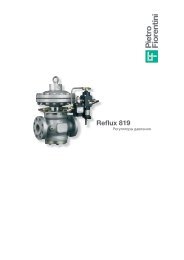
Reflux 919 - Syncroflux - VLM<br />
Q = KG (Pu - Pd) Pd Q = 16,8 x Cv x Pu x sin 106,78<br />
KG<br />
Q x<br />
= 2<br />
2 > Vice versa, when the values of Pu, Pd and Q are known, calculate the values of Cv, Cg or KG with:<br />
KG =<br />
Q<br />
Pd ( Pu - Pd )<br />
Cv =<br />
Pu - Pd<br />
Pu Q= 16,8 x Cv x Pu Q= 0,526 x Cg x Pu (valid for Pu ≥ 2 x Pd)<br />
Q<br />
.16,8x<br />
Pux<br />
sinx<br />
106,78<br />
Pu - Pd<br />
((<br />
Pu<br />
(valid for Pu < 2 x Pd)<br />
2.2 > in critical conditions: x Q<br />
KG =<br />
(valid for Pu ≥ 2 x Pd)<br />
Pu<br />
2<br />
Q<br />
Q<br />
Cv =<br />
Cg =<br />
16,8 x Pu<br />
0,526 x Pu<br />
Pu<br />
(valid for Pu < 2 x Pd)<br />
Q<br />
A oversizing of 20% on calculated values is raccomanded. Cg formulae give flow rate values more correct while<br />
KG formulae give values 5% higher than real ones only in noncritical conditions. In the case of noise limitation level<br />
a speed at the outlet flange of 130 m/sec. it is also raccomanded. Above formulae are valid for natural gas with a<br />
relative specific gravity of 0,61 compared to air and temperature of 15° C at inlet. For gases with different relative<br />
specific gravity (S) and temperature t (in °C) ), value of flow rate calculated as above, must be adjusted multiplying<br />
by:<br />
175.8<br />
Fc =<br />
S x ( 273.15 + tu )<br />
Reflux 919 - Syncroflux - VLM<br />
Nominal diameter (mm)<br />
Size (inches)<br />
Cg flow coefficient<br />
KG flow coefficient<br />
Cv flow coefficient<br />
Q = 0,526 x Cg x Pu x sin<br />
25<br />
1"<br />
575<br />
605<br />
18<br />
50<br />
2"<br />
2200<br />
2335<br />
69<br />
106,78<br />
80<br />
3"<br />
4937<br />
5194<br />
154<br />
Pu - Pd<br />
100<br />
4"<br />
8000<br />
8416<br />
250<br />
Pu<br />
Cg =<br />
150<br />
6"<br />
16607<br />
17471<br />
519<br />
200<br />
8"<br />
25933<br />
27282<br />
810<br />
250<br />
10"<br />
36525<br />
38425<br />
1141<br />
( (<br />
( (<br />
0,526 . xPux<br />
sinx<br />
106,78<br />
Pu - Pd<br />
((<br />
Pu