Soft Computing Applications on SR-30 Turbojet Engine
Soft Computing Applications on SR-30 Turbojet Engine
Soft Computing Applications on SR-30 Turbojet Engine

You also want an ePaper? Increase the reach of your titles
YUMPU automatically turns print PDFs into web optimized ePapers that Google loves.
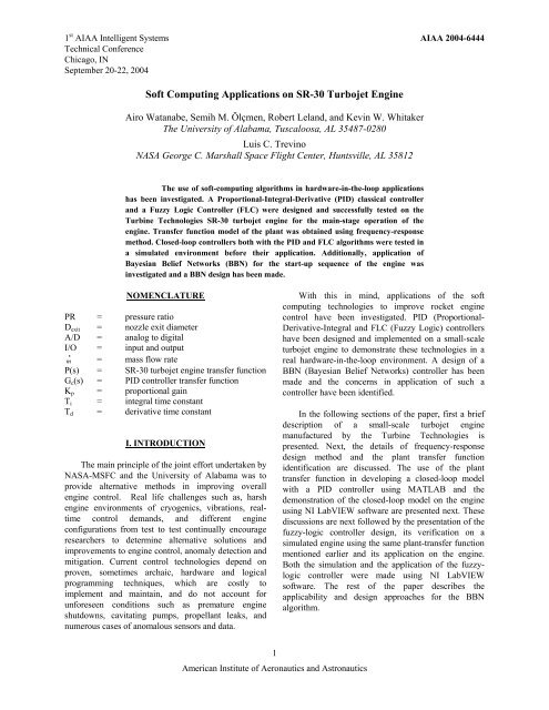
AIAA 2004-6444II. <strong>SR</strong>-<strong>30</strong> TURBOJET ENGINE AND FACILITYTurbine Technologies’ <strong>SR</strong>-<strong>30</strong> <strong>Turbojet</strong> <strong>Engine</strong>The <strong>SR</strong>-<strong>30</strong> engine is a turbojet engine with asingle-stage radial-flow compressor with a maximumpressure ratio of, PR=3.4, a single-stage axial-flowturbine, and a reverse-flow annular combusti<strong>on</strong>chamber and it operates obeying the Brayt<strong>on</strong>thermodynamic cycle in the same fashi<strong>on</strong> as largeturbojet engines (Figure 1). The engine, as produced byTurbine Technologies, includes five pressuretransducers, five thermocouples, a load-cell for thrustmeasurements, a custom motor winding for reading theengine RPM, and a fuel-flow-rate measurement systemto m<strong>on</strong>itor/measure the operating parameters of theengine. The engine generates . 20 lbs of thrust at 90,000RPM while ingesting m = 1.1 lb/sec of air. The enginehas a length of 10.75 in., and the exit exhaust diameterof D exit =2.25 inches. Further details can be found in thepaper by Watanabe et. al [1].the A/D board using cables. While <strong>on</strong>e of these units(NI-SC-2345) houses the thermocouple input modules(NI-SCC-TC02), the millivolt range input modules (NI-SCC-AI06), a c<strong>on</strong>nector block for digital outputsignals, and the analog output modules, the other unit(NI-CA-1000) houses a c<strong>on</strong>nector block (NI-CB-68LPR) to c<strong>on</strong>nect other analog inputs. Each inputmodule includes self-c<strong>on</strong>tained signal-c<strong>on</strong>diti<strong>on</strong>ingunits such as low pass filters and instrumentati<strong>on</strong>amplifiers.While the thermocouple input modules are used toread the temperatures, the millivolt input range modulesare used to read the load-cell output voltage and <strong>on</strong>e ofthe pressure signals. Digital I/O lines are used togenerate TTL signals to turn <strong>on</strong> and off the relays.Relays (BASCO Company, ELK 924) are used toreplace manual switches, which are used to start and tostop the igniti<strong>on</strong>, the fuel flow and to turn <strong>on</strong> and offthe valve for high-pressure air.Fuel Flow Valve C<strong>on</strong>trollerThe c<strong>on</strong>trol output signal for the Single-inputsingle-output(SISO) system under study is the signal toc<strong>on</strong>trol the fuel-flow rate. The fuel-flow rate in theengine is adjusted by c<strong>on</strong>trolling valve opening toobtain a desired thrust value. The operati<strong>on</strong> of thec<strong>on</strong>trol-valve is automated with the use of aCompumotor-ES22BS stepper motor. The ES22BSstepper motor is mounted <strong>on</strong> a simple stand to hold themotor steadily. The stepper motor has a maximumtorque of 9.4 lb-in, a maximum resoluti<strong>on</strong> of 128,000Step/rev with the use of the GT-L5 drive, and the shaftinertia is 1.1 oz-in 2 .Figure 1 <strong>SR</strong>-<strong>30</strong> <strong>Turbojet</strong> <strong>Engine</strong>The engine system is equipped with a dataacquisiti<strong>on</strong> board, additi<strong>on</strong> of c<strong>on</strong>necti<strong>on</strong> panels for thesensors, a stepper motor as fuel-flow rate valvepositi<strong>on</strong>er, and several relays to c<strong>on</strong>trol severalswitches for engine operati<strong>on</strong>.Data Acquisiti<strong>on</strong> SystemThe current system at the University of Alabamaincludes a Nati<strong>on</strong>al Instruments NI PCI-6031E A/Dboard, which has a 16-bit resoluti<strong>on</strong>, 100 kSamples/secsampling rate, 64 analog input, 2 analog output, and 8digital I/O ports. Signal c<strong>on</strong>necti<strong>on</strong>s to the A/D boardare made using two enclosures, which are attached to2American Institute of Aer<strong>on</strong>autics and Astr<strong>on</strong>auticsIII. PID CONTROLLER DESIGN USING THEFREQUENCY-RESPONSE METHODA PID type classical c<strong>on</strong>troller was designed andimplemented using the frequency-resp<strong>on</strong>se method toidentify and learn the engine characteristics duringclosed-loop operati<strong>on</strong>s. This secti<strong>on</strong> outlines the stepby-stepdesign of the PID c<strong>on</strong>troller and the results ofits implementati<strong>on</strong>.A series of data sets for the frequency-resp<strong>on</strong>sedesign was obtained using a LabVEW program. Thechosen input and output for the plant, the <strong>SR</strong>-<strong>30</strong>turbojet engine, are the fuel flow valve positi<strong>on</strong> indegrees and the thrust force in pounds, respectively. Togive the sinusoidal input excitati<strong>on</strong>, the valve positi<strong>on</strong>was excited in a sine-wave manner with 5 degrees of amean positi<strong>on</strong>, corresp<strong>on</strong>ding to a steady-state thrustvalue of about 5.3 pounds, and 4 degrees of peak-to-
AIAA 2004-6444peak amplitude. Different frequencies of the excitati<strong>on</strong>were attempted to cover a frequency range of interest.In order to c<strong>on</strong>struct a pair of Bode Plots for thefrequency-resp<strong>on</strong>se design method, gains and phasesneed to be calculated in the regi<strong>on</strong> of frequencies.However, raw measurements of signals fromtransducers usually c<strong>on</strong>tain noise. The load-cell systemof the <strong>SR</strong>-<strong>30</strong> engine is not an excepti<strong>on</strong> and the thrustoutput signal c<strong>on</strong>tains such noise. Therefore, the thrustoutput signal was c<strong>on</strong>diti<strong>on</strong>ed using the “filtfilt”command of MATLAB is used to c<strong>on</strong>diti<strong>on</strong> the thrustoutput signals. After the signal c<strong>on</strong>diti<strong>on</strong>ing, the peaksof the thrust output were found by seeking sign changesof signal derivatives. A Gain at each frequency wascalculated finding an average of the peak-to-peakvalues. An example of the raw measurement and thefiltered signals of the thrust output with the input signalfrequency of 6.0 rad/sec are shown in Figure 2.Thrust Output [lbs]0.<strong>30</strong>.20.10.00 1 2 3 4 5-0.1-0.2-0.3Time [sec]Figure 2 Raw and Filtered ThrustIII-A. PLANT IDENTIFICATIONfilteredThe frequency regi<strong>on</strong> of our interest ranges from0.1 rad/sec to 11.0 rad/sec. The data obtained from thesine-wave data collecti<strong>on</strong> is plotted <strong>on</strong> the pair of BodeDashed/SL App.Solid/ModelStar/F-R DataFigures 3a & 3b Open-Loop Bode PlotsrawDashed/Model without DelaySolid/Model with DelayStar/F-R Data-180plots in Figures 3a and 3b. The plant is modeled withMATLAB. Assuming a sec<strong>on</strong>d order system, cornerfrequencies of 0.5 and 9.0 rad/sec were identified. Theassumed open-loop transfer functi<strong>on</strong> of the plant is:4.5P =(1)() s( s + 0.5)( s + 9.0)Although, the first-estimated model, the red solidline, matches in a satisfactory manner in the magnitudeBode plot, there is an obvious discrepancy between thefirst-estimated model (black-dashed) and the frequencyresp<strong>on</strong>sedata in the phase Bode plot. Therefore, thepresence of a time-delay in the model was suspected.After several attempts of time-delay modeling, adding0.2 sec<strong>on</strong>ds of time-delay model with the MATLAB“pade” command to the plant (red-solid) showed ac<strong>on</strong>sistent matching with the frequency-resp<strong>on</strong>se data.The estimated model with the time delay is plotted inthe Bode plots with dashed-blue lines. The assumedopen-loop transfer functi<strong>on</strong> of the plant with the timedelayis:P() s4.5−0.2s= e (2)( s + 0.5)( s + 9.0)The assumed open-loop transfer functi<strong>on</strong> of theplant with the 4 th order “pade” approximati<strong>on</strong> timedelay is:( )( )( )( )( )( )224.5 s −57.9s+ 914 s − 42.1s+ 1149P()s =22s + 0.5 s + 9.0 s + 57.9s+ 914 s + 42.1s+ 1149….(3)III-B. PID CONTROLLER DESIGN AND TESTProporti<strong>on</strong>al-Integral-Derivative (PID) c<strong>on</strong>trolapproach was chosen for the engine c<strong>on</strong>trol since it is<strong>on</strong>e of the popular closed-loop c<strong>on</strong>trol approaches thatcan be applied to a wide range of engineering problems.One customary representati<strong>on</strong> of such c<strong>on</strong>troller can beexpressed as:⎛ 1()⎟ ⎞G⎜cs = Kp1 + + Tds (4)⎝ Tis ⎠After attempting several combinati<strong>on</strong>s of numbersfor the PID gains using MATLAB SISO tool program,a combinati<strong>on</strong> of K p = 3.68, T i = 2.16 sec, and T d =0.061 sec was found to be a reas<strong>on</strong>able c<strong>on</strong>troller forthe applicati<strong>on</strong>.3American Institute of Aer<strong>on</strong>autics and Astr<strong>on</strong>autics
AIAA 2004-6444Figure 4, shows that the proposed c<strong>on</strong>troller gives apositive gain margin of 12.6 db and a positive phasemargin of 65.8 deg, which make the system stable.Since the system has a positive gain margin, there is atolerance of raising the proporti<strong>on</strong>al gain of the PIDc<strong>on</strong>troller.Cutoff frequency is the maximum frequency at whichthe output of a system will track an input sinusoid in asatisfactory manner.6.05.55.0Thrust [lbs]4.54.03.53.02.52.00 1 2 3 4 5 6Time [sec]Figure 7 Step Resp<strong>on</strong>ses from <strong>SR</strong>-<strong>30</strong> <strong>Engine</strong>Figure 4 Open-Loop Bode PlotsFigure 5 is the closed-loop Bode plots for thesystem. From the gain plot, the proposed closed-loopmodel has a cutoff frequency of about 3.01 rad/sec.Step input tests were c<strong>on</strong>ducted to test the designedPID c<strong>on</strong>troller. Figure 6 is the result from estimatedmodel using MATLAB. It shows a rise time of 0.65 secand a settling time of 1.15 sec. Figure 7 shows theexperimental results of step input tests using the <strong>SR</strong>-<strong>30</strong>engine. In the figure, three cases were plotted. For eachcase, a step command was issued at t = 1.0 sec. Thethrust values for the three cases were 3.5, 4.0, and 5.0lbs. For all cases the results show about 2 sec<strong>on</strong>ds ofsettling time with near zero steady-state errors.The large initial jump observed in the 3 to 5 lbincrease thrust run is undesirable and it is due tounforeseen n<strong>on</strong>linear effects. This jump does not appearwhen using the fuzzy c<strong>on</strong>troller.IV. FUZZY LOGIC CONTROLLER DESIGN ANDAPPLICATION [2]Figures 5 Closed-Loop Bode PlotsThe employment of Bayesian and fuzzy techniquesderive from the “soft computing” family of algorithms.Here “soft computing” refers to computati<strong>on</strong>almechanisms that can determine suitable relati<strong>on</strong>ships(in a system data set) to assess and determine aquantitative opini<strong>on</strong>(s) based <strong>on</strong> future c<strong>on</strong>diti<strong>on</strong>s.Since the scope of this paper is not <strong>on</strong> the depth ofunderstanding Bayesian and fuzzy techniques,applicati<strong>on</strong> of them is presented. In short, withinMSFC, such computati<strong>on</strong>al mechanisms are viewed asa collecti<strong>on</strong> of algorithms that can achieve optimal ornear-optimal results in the presence of imprecise data,uncertainty [3], unknown physics, and probabilisticoutcomes. The central goal in soft computing is toattain more robust resp<strong>on</strong>se.Figure 6 Simulated Unit Step Resp<strong>on</strong>se4American Institute of Aer<strong>on</strong>autics and Astr<strong>on</strong>autics
AIAA 2004-6444Similar to the PID design, for main-stage c<strong>on</strong>trol, afuzzy logic c<strong>on</strong>troller was designed and implemented toc<strong>on</strong>trol the <strong>SR</strong>-<strong>30</strong> engine and the resp<strong>on</strong>se of the engineto a step input using the PID and Fuzzy c<strong>on</strong>trollers wascompared. The use of fuzzy logic was seen suitablesince it accommodates the uncertainties associated withc<strong>on</strong>troller architecture. Fuzzy logic is a branch ofmathematics that deals with approximate reas<strong>on</strong>ing.Fuzzy logic, developed by Lotfi A. Zadeh of theUniversity of California at Berkely, combines the topicsof multi-valued logic, probability theory, and artificialintelligence for simulati<strong>on</strong> of human thoughts by usingcomputer software as a medium. The technology offuzzy logic enables a computer to make decisi<strong>on</strong>s based<strong>on</strong> vagueness or imprecisi<strong>on</strong> intrinsic in most physicalsystems. Fuzzy logic also provides a c<strong>on</strong>venient way tointroduce useful n<strong>on</strong>linearities into the c<strong>on</strong>trol law toachieve specific effects, such as reducing largeovershoots. In depth details of fuzzy logic are outside toscope of this paper. A more detailed descripti<strong>on</strong> <strong>on</strong>fuzzy logic can be found in [5].In the rest of this secti<strong>on</strong> the fuzzy logic c<strong>on</strong>trollerdesign and related programming process are discussed.A brief descripti<strong>on</strong> of the design of the fuzzy logicc<strong>on</strong>trol algorithm is introduced. A simulati<strong>on</strong> programwritten to test the fuzzy logic c<strong>on</strong>troller and the resultsof the simulati<strong>on</strong> are discussed. Implementati<strong>on</strong> of thefuzzy logic c<strong>on</strong>trol algorithm <strong>on</strong> the <strong>SR</strong>-<strong>30</strong> engineusing LabVIEW is detailed and the hardware-in-thelooptest results are discussed.IV-A.FUZZY LOGIC ALGORITHMDESCRIPTIONFuzzy Logic algorithm differs from the PID c<strong>on</strong>trolalgorithm since it can be used for n<strong>on</strong>-linear-timevariantsystems. The algorithm intends to mimic humanthoughts in the sense that the relati<strong>on</strong> between an inputand its output is assessed by a user, depending <strong>on</strong> theuser’s experience. In the fuzzy logic terminology,vague terms used such as hot, and cold are calledlinguistic terms and range of real numbers for the inputand the output is referred to as universe of discourse.Range of the input values divided into secti<strong>on</strong>s by itslinguistic terms is called antecedence and range ofoutput values divided into secti<strong>on</strong>s by its linguisticterms is called c<strong>on</strong>sequence.In a fuzzy logic c<strong>on</strong>trol system, the fuzzificati<strong>on</strong>process translates real input values to linguistic inputvalues, next the fuzzy inference system drives a5American Institute of Aer<strong>on</strong>autics and Astr<strong>on</strong>auticsc<strong>on</strong>clusi<strong>on</strong> in a form of linguistic output valuesaccording to its rule base, which resembles IF-THENstructure used in many text-based programminglanguages. The final process called the defuzzificati<strong>on</strong>process translates back the linguistic output values tocorresp<strong>on</strong>ding real output values for subsequent c<strong>on</strong>trolacti<strong>on</strong>s.IV-B. FUZZY LOGIC CONTROLLERARCHITECTUREThe NI LabVIEW Fuzzy Logic C<strong>on</strong>troller Toolkitwas used to develop fuzzy logic c<strong>on</strong>trollers for the <strong>SR</strong>-<strong>30</strong> engine c<strong>on</strong>trol applicati<strong>on</strong>. The toolkit allows theuser to interface with LabVIEW programs. The FuzzySet Editor specifies the details of the fuzzificati<strong>on</strong> step,and the details of defuzzificati<strong>on</strong> step. The Rule BaseEditor of the Fuzzy Logic C<strong>on</strong>troller Toolkit enablesthe user to specify the details of the fuzzy inferencesystem. Before testing a fuzzy logic algorithm with the<strong>SR</strong>-<strong>30</strong> engine, a LabVIEW-fuzzy simulati<strong>on</strong> programwas developed using the plant model identified in thedesign process of the PID c<strong>on</strong>troller. The fuzzysimulati<strong>on</strong> program had similar inputs to the <strong>on</strong>es of theLabVIEW-PID c<strong>on</strong>troller and the c<strong>on</strong>troller outputagain was the fuel-flow valve positi<strong>on</strong>. The fuzzysimulati<strong>on</strong> program calculates appropriate valvepositi<strong>on</strong> in every loop executi<strong>on</strong> for adjusting the fuelflowvalve opening to obtain desired thrust. A picture ofthe Labview fuzzy simulati<strong>on</strong> program developed forthis purpose is shown in Figure 10. The input variablesused in the design of the PD part of the c<strong>on</strong>troller werethrust error calculated at node (1) and thrust error ratecalculated at node (2). As for the integral part of theprogram, the thrust error was the <strong>on</strong>ly input variable.The PD part and the integral part evaluate their outputsto the stepper motor separately from their inputs. Thesum of the angle outputs calculated at node (3) fromthe two parts is the total angle output to the steppermotor to c<strong>on</strong>trol the fuel-flow valve positi<strong>on</strong>.The Figure 11-A shows the architectures of thefuzzy sets associated with the thrust error and the thrusterror rate as the c<strong>on</strong>troller inputs and the Figure 11-Bshows the architectures of the fuzzy sets associated withthe valve positi<strong>on</strong> and the valve positi<strong>on</strong> error (SeeTable 1 for the corresp<strong>on</strong>ding linguistic values for eachoutput). The use of the thrust error and thrust error rateeach with five linguistic terms results in 5 2 = 25 rulesfor the PD part. The use of the thrust error with fivelinguistic variables results in five more rules for theintegral part bringing the number of the total rules tothirty. The choice of using thirty rules gives areas<strong>on</strong>able number of rules and allows the user to
AIAA 2004-6444Integral Part1PD Part32<strong>Engine</strong> ModelFigure 10: Fuzzy Logic Simulati<strong>on</strong> VI (wiring diagram)1.0N MN Z MP P1.0N MN Z MP P0.50.50.00.0-11.0 -5.5 0.0 5.5 11.0a b c d e f gA) INPUTSB) OUTPUTSFigure 11: Fuzzy Sets Associated with Thrust Error and Thrust Error Rate Inputs and FuzzySets associated with Valve Positi<strong>on</strong> and Valve Positi<strong>on</strong> Error Outputsbenefit from the capabilities of the fuzzy logicc<strong>on</strong>troller. Since the aim of the present study was todevelop a test-bed and dem<strong>on</strong>strate the hardware-inthe-loopanalysis, a relatively simple fuzzy logic designwas used. Table 2 explains the meanings of the symbolsto express each linguistic term. Table 3 shows a pair ofthe rule bases used in the design process.Am<strong>on</strong>g the defuzzificati<strong>on</strong> methods such as theCenter-of-Maximum, the Center-of-Gravity, and theMean-of-Maximum that are available in the FuzzyLogic Toolkit, the Center-of-Maximum method wasused in the design. The Center-of-Maximum methodresults in a lesser computati<strong>on</strong> time and it also results ina linear variati<strong>on</strong> of the output variable <strong>on</strong>ce fullyoverlapping linguistic terms were used.IV-C. FUZZY LOGIC CONTROLLER TESTUSING SIMULATED ENGINEThe LabVIEW-fuzzy logic c<strong>on</strong>troller design wasfirst tested in a LabVIEW simulati<strong>on</strong> model using theplant transfer functi<strong>on</strong> identified in the PID c<strong>on</strong>trollerdesign process. It was assumed that the fuzzy logicc<strong>on</strong>trol algorithm would be applicable to this enginec<strong>on</strong>trol applicati<strong>on</strong> because the architecture of thealgorithm is capable of handling n<strong>on</strong>-linearity. In thedesign of the fuzzy logic algorithm, several differentuniverse of discourse ranges were tested for the6American Institute of Aer<strong>on</strong>autics and Astr<strong>on</strong>autics
AIAA 2004-6444Thrust [lbs]andValve Positi<strong>on</strong> [deg]antecedence and the c<strong>on</strong>sequence ranges. The bestranges were identified which gave the least rise timewithout an overshoot.Step Input Test: Figure 12 shows a unit step resp<strong>on</strong>sefrom the simulati<strong>on</strong> model, which includes the plantmodel and the fuzzy logic c<strong>on</strong>troller. The valve positi<strong>on</strong>very quickly rises to 3.6 degrees within 0.33 sec<strong>on</strong>ds.The simulated time delay is visible with about 0.2sec<strong>on</strong>ds. The thrust output from the plant modelincreases without an overshoot to the desired thrustvalue within 3.0 sec<strong>on</strong>ds. The number below thehoriz<strong>on</strong>tal axis in Figure 12 represents the number ofloops executed and the rate of the loop executi<strong>on</strong> was25 time/sec.ThrustThrust DesiredValve Positi<strong>on</strong>Figure 12: Step Resp<strong>on</strong>se from Simulati<strong>on</strong> Model.Twenty-five steps corresp<strong>on</strong>d to 1 sec<strong>on</strong>d.stepsSystem Resp<strong>on</strong>se with Limits <strong>on</strong> the Valve positi<strong>on</strong>:The fuzzy c<strong>on</strong>troller design was also tested to observethe effects <strong>on</strong> the system resp<strong>on</strong>ses if valve positi<strong>on</strong>limits were set. The valve positi<strong>on</strong> limits were requiredbecause the c<strong>on</strong>troller tries to move the linkage out ofthe possible range of the moti<strong>on</strong>. The reas<strong>on</strong> of thenecessity for the limits is shown in Figure 13. Once thedesired thrust is obtained and subsequently decreasedback to a lower value, the valve positi<strong>on</strong> needs to bereduced below zero degrees, which is not achievabledue to the physical c<strong>on</strong>straints of the fuel-flow valvesystem. Additi<strong>on</strong>ally, changing the valve positi<strong>on</strong> tobelow a certain angle would result in the engine to shutdown. Although the effect of the minimum angle limitset results in a much slower resp<strong>on</strong>se of the engine, it isrequired to avoid any damage to the engine. In order toeliminate such c<strong>on</strong>trol scenarios occurring, limits <strong>on</strong> theintegral c<strong>on</strong>troller was placed. The integrated c<strong>on</strong>trolangle and the c<strong>on</strong>trol angle sent to the engine were resetto zero <strong>on</strong>ce the c<strong>on</strong>troller required an angle belowzero. The number below the horiz<strong>on</strong>tal axis in Figure13 also represents the number of loops executed and therate of the loop executi<strong>on</strong> was 25 /sec.IV-D. FUZZY LOGIC CONTROLLER TESTWITH <strong>SR</strong>-<strong>30</strong> TURBOJET ENGINEThe Fuzzy Logic C<strong>on</strong>troller LabVIEW-Virtual-Instrument was next tested to c<strong>on</strong>trol the <strong>SR</strong>-<strong>30</strong> engine.In order to compare the resp<strong>on</strong>se of the simulated andthe actual <strong>SR</strong>-<strong>30</strong> engine resp<strong>on</strong>ses, the same type of astep input test was attempted. The results are shown inFigure 14 (Case 1), Figure 15 (Case 2). Different rangesof the linguistic variable for the valve positi<strong>on</strong> outputwere used for each case while the same ranges of thelinguistic variables for the inputs were used with the<strong>on</strong>es in the simulati<strong>on</strong>. Refer to Figure 11 and Table 1for the numbers used for each case.A step command of 4.5 pounds was issued fromthe idling operati<strong>on</strong> status for each case. Figure 14shows the result from the first attempt and the samefuzzy inference system used in the test simulati<strong>on</strong> wasused for this case. There was an oscillati<strong>on</strong> in the valvepositi<strong>on</strong> trying to achieve the desired thrust numbersince the thrust was not getting a steady state. In FigureThrust [lbs] and Valve Positi<strong>on</strong> [deg]5.0desired thrust4.54.03.5thrust3.02.5valve positi<strong>on</strong>2.01.51.0145 147 149 151 153 155 157 159Time [sec]Figure 14: Step Resp<strong>on</strong>se from <strong>SR</strong>-<strong>30</strong> <strong>Engine</strong> Case 17American Institute of Aer<strong>on</strong>autics and Astr<strong>on</strong>autics
AIAA 2004-644415, the result from the sec<strong>on</strong>d attempt is shown. Asteady state was achieved in about 5.0 sec<strong>on</strong>ds with anear no-steady error. Although the settling time wasl<strong>on</strong>ger than the <strong>on</strong>e observed in the simulati<strong>on</strong> using thePID c<strong>on</strong>troller, the performance of the fuzzy c<strong>on</strong>trollerfor this case showed an improvement over the first case.Figure 15 shows a good agreement with the simulati<strong>on</strong>result shown in Figure 12.to Pearl’s treatment of the subject [4]. The specificBBN approach to be employed in this effort is shown inFigure 16 and its basic procedure is bey<strong>on</strong>d the scope ofthis paper. The basic steps are listed below.λ X (u)Uπ X (u)Thrust [lbs] and Vavle Positi<strong>on</strong> [deg]5.04.54.03.53.02.52.01.51.0desired thrustthrustvalve positi<strong>on</strong>161 163 165 167 169 171 173 175Time [sec]Figure 15: Step Resp<strong>on</strong>se from <strong>SR</strong>-<strong>30</strong> <strong>Engine</strong> Case 2V. BAYESIAN BELIEF NETWORKSCONTROLLER DESIGN [2]For the engine start phase, the primary softcomputing technology to be utilized is Bayesian beliefnetworks (BBN). The sole intent of the BBN is toqualify each of the states during engine start-up prior toreaching main-stage. This will further assure certaintyin the health of the engine and proceeding into mainstagein additi<strong>on</strong> to providing added assurance intopreventing any premature engine shutdowns.BBN’s have been proven to be good predictive anddiagnostic mechanisms for reas<strong>on</strong>ing about the state ofevents in envir<strong>on</strong>ments where uncertainty is universal.Suppressing the details, the genealogy of this SCT isstr<strong>on</strong>gly rooted in classic statistical Bayesian inferencetheory where a subjectivist viewpoint is taken. In shortBayesian inference uses a different interpretati<strong>on</strong> ofprobability where <strong>on</strong>e’s degree of belief in some eventis part of the reas<strong>on</strong>ing. BBN’s are computati<strong>on</strong>alarchitectures that permit declarative (prior c<strong>on</strong>diti<strong>on</strong>alprobabilistic values) and subjective opini<strong>on</strong>s (posteriorprobabilistic values) about world (factual) knowledge tobe part of the reas<strong>on</strong>ing and assessment through avisual network representati<strong>on</strong> and a unique syntacticmessage-passing feature. Furthermore, the visualnetwork makes it easier to view the top-down cause andeffect (or c<strong>on</strong>diti<strong>on</strong> to c<strong>on</strong>sequence) relati<strong>on</strong>ships. For amore detailed account of this SCT, the reader is referred8American Institute of Aer<strong>on</strong>autics and Astr<strong>on</strong>auticsV X WYλ Y (x)π Y (x)π Z (x)λ Z (x)Figure 16 Bayesian Belief Network1. Belief Updating – When node X is activated toupdate its parameters for belief updating, it firstinspects all messages transmitted to it by its parent (π)and its children nodes (λ). Then using all input, itupdates its belief.2. Bottom-up Propagati<strong>on</strong> – Using messagestransmitted by Y&Z, compute message to transmit toparent node U.3. Top-down Propagati<strong>on</strong> – Node X then computesnew messages to be sent to its children nodes Y&Z.A first design of the Bayesian Belief Networks forthe <strong>SR</strong>-<strong>30</strong> <strong>Engine</strong> is presented in the Figure 17a and17b. Table 4 gives the initial design for the BBNalgorithm.LegendVirtual NodeUnidirecti<strong>on</strong>al BeliefPropagati<strong>on</strong>Bidirecti<strong>on</strong>al BeliefPropagati<strong>on</strong>C<strong>on</strong>tinuati<strong>on</strong>Boundary BetweenSequence &Belief NetworkAirSwitchFuelSwitch<strong>Engine</strong>Vibrati<strong>on</strong>Oil/FuelLeakageSwitchStatusIgniti<strong>on</strong>Switch3 Sec.TimerTempLimitsMasterKeySwitch<strong>Engine</strong>StartInitiatedTerminate<strong>Engine</strong>Start Seq.Figure 17a Bayesian Belief Networks for<strong>SR</strong>-<strong>30</strong> Turbo Jet <strong>Engine</strong> Start-UpThe design required analysis of the engine-start dataand careful choice of the parameters for the design. ForZOilPressureFuelSwitchElectricMasterSwitch<strong>Engine</strong>StartInitiated
AIAA 2004-6444this purpose six sets of engine-start data were acquiredand analyzed. This initial design will allow applicati<strong>on</strong>of the BBN <strong>on</strong> the existing test bed.Virtual Nodes: SensorsP1 Compressor InletP2 Compressor ExitP3 Combusti<strong>on</strong> ChamberP4 Turbine Stage ExitP5 Thrust Nozzle ExitRPM <strong>Engine</strong> Shaft SpeedFFS Fuel Flow SensorTf Thrust ForceT1 Compressor ExitT2 Compressor ExitT3 Turbine Stage InletT4 Turbine Stage ExitT5 Thrust Nozzle Exit<strong>Engine</strong>StartInitiatedP1…………………<strong>Engine</strong>StartTerminate<strong>Engine</strong>Start Seq.T05Select VirtualNodesAnomalyDetecti<strong>on</strong>Figure 17b Bayesian Belief Networks for<strong>SR</strong>-<strong>30</strong> Turbo Jet <strong>Engine</strong> Start-UpVI. CONCLUSIONSDevelopment of a test-bed for soft-computingstudies has been presented. Modificati<strong>on</strong>s <strong>on</strong> anexisting <strong>SR</strong>-<strong>30</strong> Turbine Technologies small-scaleturbojet engine included the integrati<strong>on</strong> of a new dataacquisiti<strong>on</strong>board, replacement of the manual switchesand manual lever with computer c<strong>on</strong>trolled switchesand a stepper motor. The operati<strong>on</strong> and c<strong>on</strong>trol of theengine has been automated using a PC using Nati<strong>on</strong>alInstruments LabVIEW program.Two different c<strong>on</strong>trol algorithms have beendesigned, tested in a simulated envir<strong>on</strong>ment andintegrated into the test bed. Both the PID and the fuzzylogicalgorithms have been shown to successfullyc<strong>on</strong>trol the operati<strong>on</strong> of the engine.Additi<strong>on</strong>ally a design of the BBN algorithm ispresented. The algorithm will be integrated into thesystem in a future study.REFERENCES123456Watanabe, A., Davis, R. N., Ölçmen, S. M., Polites, M. E., andTrevino, L. C., “A Test bed for Evaluating <str<strong>on</strong>g>Soft</str<strong>on</strong>g> <str<strong>on</strong>g>Computing</str<strong>on</strong>g>Technologies for Rocket <strong>Engine</strong> C<strong>on</strong>trol.” 42nd AIAAAerospace Sciences Meeting and Exhibit, Reno, NV, January05-08, 2004.Trevino, L. C., Ölçmen, S. M., and Polites, M. E., “Use of <str<strong>on</strong>g>Soft</str<strong>on</strong>g><str<strong>on</strong>g>Computing</str<strong>on</strong>g> Technologies for Rocket <strong>Engine</strong> C<strong>on</strong>trol.” 22ndDigital Avi<strong>on</strong>ics Systems C<strong>on</strong>ference, Indianapolis, IN, October12-16, 2003.Steincamp, J., First Annual Report, Marshall Space Flight Center,Huntsville, AL, September 2001.Pearl, J., “Probabilistic Reas<strong>on</strong>ing in Intelligent Systems:Networks of Plausible Inference,” Morgan KaufmannPublishers, Inc., San Mateo, CA, 1988.Zadeh, L. A., “Fuzzy Logic,” Internal Report, University ofCalifornia, Berkeley, CA, 1988.Watanabe, A. “Development of a Test-Bed for Rocket <strong>Engine</strong>C<strong>on</strong>trol Algorithm Improvement.” Masters Thesis, TheUniversity of Alabama, Tuscaloosa, AL, 2004.9American Institute of Aer<strong>on</strong>autics and Astr<strong>on</strong>autics
AIAA 2004-6444Table 1: Linguistic Values in Figure 11Case Output A B C D E F GSimulati<strong>on</strong> andCase 1 with <strong>SR</strong>-<strong>30</strong>Valve positi<strong>on</strong> -20.0 -12.5 -10.0 0.0 10.0 12.5 20.0Case 2 with <strong>SR</strong>-<strong>30</strong> Valve positi<strong>on</strong> -<strong>30</strong>.0 -18.8 -15.0 0.0 15.0 18.8 <strong>30</strong>.0Case 3 with <strong>SR</strong>-<strong>30</strong> Valve positi<strong>on</strong> -35.0 -21.9 -17.5 0.0 17.5 21.9 35AllValve positi<strong>on</strong>error-1.6 -0.8 -0.2 0.0 0.2 0.8 1.6Table 2: Linguistic TermsN1I thrust error is negative N1O valve positi<strong>on</strong> change will be negativeMN1I thrust error is medium negative MN1O valve positi<strong>on</strong> change will be medium negativeZ1I thrust error is near zero Z1O valve positi<strong>on</strong> change will be near zeroMP1I thrust error is medium positive MP1O valve positi<strong>on</strong> change will be medium positiveSP1I thrust error is positive P1O valve positi<strong>on</strong> change will be positiveN2I thrust error rate is negative N2O adjustment for valve positi<strong>on</strong> error will be negativeMN2I thrust error rate is medium negative MN2O adjustment for valve positi<strong>on</strong> error will be medium negativeZ2I thrust error rate is near zero Z2O adjustment for valve positi<strong>on</strong> error will be near zeroMP2I thrust error rate is medium positive MP2O adjustment for valve positi<strong>on</strong> error will be medium positiveP2I thrust error rate is positive P2O adjustment for valve positi<strong>on</strong> error will be positiveTable 3: Rule Bases for Valve Positi<strong>on</strong> and Valve Positi<strong>on</strong> Error OutputsN1I MN1I Z1I MP1I P1IN2I N1O MN1O MN1O MN1O Z1O N1I MN2OMN2I N1O MN1O Z1O Z1O Z1O MN1I MN2OZ2I MN1O MN1O Z1O MP1O MP1O Z1I Z2MP2I Z1O Z1O Z1O MP1O P1O MP1I MP2OP2I Z1O MP1O MP1O MP1O P1O P1I MP2OValve Positi<strong>on</strong> Output Valve Positi<strong>on</strong> Error Output10American Institute of Aer<strong>on</strong>autics and Astr<strong>on</strong>autics
AIAA 2004-6444Table 4: <strong>SR</strong>-<strong>30</strong> Turbo Jet <strong>Engine</strong> Bayesian Design ParametersLink Matrices (M): All link matrices (c<strong>on</strong>diti<strong>on</strong>al probabilities) are unity for c<strong>on</strong>venienceMaster Key Switch Prior: π MKS = [0.95 0.05 ] [Probability True Probability False]Electric Master Switch Prior: π EMS = [0.99 0.01]<strong>Engine</strong> Start Initiated Start Node Prior: π ESI = [0.99 0.01]<strong>Engine</strong> Start Node Prior: π ES = [0.99 0.01]Temperature (T) LikelihoodProbabilitiesT1 & T2 DisabledT3 Compressor Exit(Normalizati<strong>on</strong> Factor 1200)T4 Turbine ExitT5 Nozzle Exitλ T3 [-∞ → e/s] = [ 0 1 ][e/s → 5 ] = [ 0.15 0.85 ]λ T4 [-∞ → e/s] = [0 1][e/s → 5 ] = [ 0.15 0.85 ]λ T5 [-∞ → e/s] = [0 1][e/s → 5 ] = [ 0.10 0.9 ]Probability Probability[ Too High Too Low ]e/s = engine startPressure LikelihoodProbabilitiesP1 Compressor InletP2 Compressor ExitP3 Combusti<strong>on</strong> ChamberP4 Turbine Stage ExitP5 Thrust Nozzle Exitλ P2 [-∞ → e/s] = [ 0 1 ][e/s → 9 ] = [ 0.05 0.95 ]λ P3 [-∞ → e/s] = [0 1][e/s → 9 ] = [ 0.1 0.9 ]λ P4 [-∞ → e/s] = [0 1][e/s → 9 ] = [ 0.05 0.95 ]λ P5 [-∞ → e/s] = [0 1][e/s → 9 ] = [ 0.1 0.9 ]λ RPM [-∞ → e/s] = [0 1][e/s → 9 ] = [ 0.1 0.9 ]λ Thrust [-∞ → e/s] = [0 1][e/s → 9 ] = [ 0.10 0.9 ]λ Flow [-∞ → e/s] = [0 1][e/s → 9 ] = [ 0.05 0.95 ]Probability Probability[ Too High Too Low ](Note: > 0.65)(Note: > 0.625)(Note: > 1)(Note: > 4800)(Note: > 3.5)(Note: > 1.7)11