BUW524 - DSL electronic ® GmbH
BUW524 - DSL electronic ® GmbH
BUW524 - DSL electronic ® GmbH

Create successful ePaper yourself
Turn your PDF publications into a flip-book with our unique Google optimized e-Paper software.
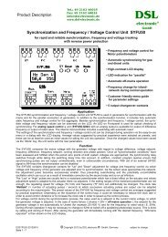
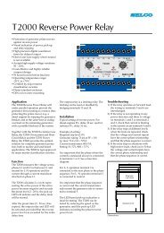
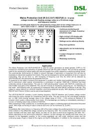
Product descriptionTel.: 49 2162 40025Fax: 49 2162 40035info@dsl-<strong>electronic</strong>.dewww.dsl-<strong>electronic</strong>.deDC Voltage Monitor <strong>BUW524</strong>(Battery Undervoltage Monitor)Display and monitoring unit for DC voltage supplies and batteriesOther voltages and undervoltage / overvoltage monitoring on request !<strong>DSL</strong><strong>electronic</strong> ®<strong>GmbH</strong>• Permanent voltage measurement and display• Customer-friendly menu for setting the parameters• Storage of the parameters in the internal memory• Switching threshold, hysteresis and switching delay adjustable• Optical display for voltages below the switching threshold set• Optical display of relay energization after expiry of the delay time• Simultaneous display of the voltage when the unit is energized• Potential-free change-over contacts 5A / 250V~• Narrow top-hat rail housingApplications:The DC voltage monitor <strong>BUW524</strong> is used for monitoring the lower limit of a low DC voltage in the 10 – 33Vrange, for example the starter battery voltage in the genset field or the DC voltage supply of connected controlsor systems.<strong>BUW524</strong> does not require a separate auxiliary voltage, instead being supplied directly from the measuringvoltage.The DC voltage measured is displayed constantly on the digital display. The relay with change-overcontact on the output side switches off when the voltage falls below the specified voltage and the time delayexpires.The undervoltage threshold value, the hysteresis and the time delay can be changed with the help of auserfriendly operating menu (see below).When an undervoltage occurs, display L-1 initially alternates with the instantaneous voltage. After expiry of thedelay time, display L-2 alternates with the instantaneous voltage and the output relay is de-energized. If thevoltage goes beyond the hysteresis and reaches the normal range again, the relay is energized immediately.The output terminals with potential separation can be evaluated by the user as desired.Relay function:DC voltage in the normal range: Relay energized Contacts: 1 – 2 open, 2 – 3 closedDC voltage in undervoltage: Relay is de-energized Contacts: 2 – 3 open, 1 – 2 closed(Voltage error)(After time delay)Above undervoltage + Hyster.: Relay is energized Contacts: 1 – 2 open, 2 – 3 closed(Switches back)(No time delay)G0<strong>BUW524</strong>-20101116 © Copyright 2010 by <strong>DSL</strong>-<strong>electronic</strong> ® <strong>GmbH</strong>, Germany Subject to changeSeite 1 - 3
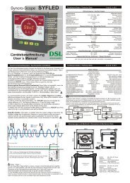
Parameterization:The „Mode“ and „Set“ keys are used to set the undervoltage threshold value, the hysteresis and the delay timefor de-energization of the relay.Each key must be pressed for approx. 1 second before data are taken over. The menu must be called upagain for each value to be set.If, during the setting process, no key is pressed after approx. 20 seconds, the program switches back to normalmode automatically. The unit does not react to changes to the measuring voltage occuring while settings arebeing made via the menu! When parameterization values falling outside of the valid range are saved, the unitreacts by displaying Er3. The value must be re-entered and can be saved if valid.1. Setting the threshold value for the undervoltage „U“To open the setting menu: 1 x „Mode“ and 2 x „Set“ (public password = 2).To set the undervoltage:2 x „Mode“, set the flashing digit via „Set“ and go to the next digit via„Mode“.After the last digit has been set, the decimal place is set and confirm via “Mode”To cancelTo saveDisplay = „A“ confirm with „Mode“ if desired (no save command).Press „Set“, display = „S“, confirm via „Mode“. The change is now saved.2. Setting the hysteresis „HU“To open the setting menu: 1 x „Mode“ and 2 x „Set“ (public password = 2)To set the hysteresis: 1 x „Mode“, 1 x „Set“ and 1 x „Mode“Set the flashing digit via „Set“ and go to the next digit via „Mode“.After the last digit has been set, the decimal place is set and confirm via „Mode“To cancelTo saveDisplay = „A“ confirm with „Mode“ if desired (no save command).Press „Set“, display = „S“, confirm via „Mode“. The change is now saved.3. Setting the delay time „TU“To open the setting menu: 1 x „Mode“ and 2 x „Set“ (public password = 2)To set the delay time: 1 x „Mode“, 2 x „Set“ and 1 x „Mode“Set the flashing digit via „Set“ and go to the next digit via „Mode“.After the last digit has been set, the decimal place is set and confirm via „Mode“To cancelTo saveDisplay = „A“ confirm with „Mode“ if desired (no save command).Press „Set“, display = „S“, confirm via „Mode“. The change is now saved.G0<strong>BUW524</strong>-20101116 © Copyright 2010 by <strong>DSL</strong>-<strong>electronic</strong> ® <strong>GmbH</strong>, Germany Subject to changeSeite 2 - 3
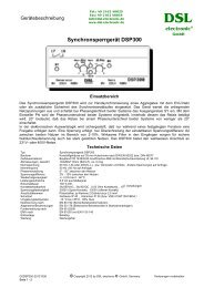
Factory setting:Untervoltage (U): 24,0V Hysteresis (HU): 0,3V Delay time (TU): 1 SekundeEr1:Er2:Er3:Error messages:Eeprom code does not match program specification.ID in Eeprom missing (blank Eeprom).Parameter entry falls outside of the valid range. Repeat entry with new parameter.Technical Data :TypeBattery undervoltage monitor <strong>BUW524</strong>Design Plastic housing PA on 35 mm hat rail acc. to DIN EN 50022 / DIN 46277Material of housingABS with fire protection UL 94 V-ODimensions, weight26x75x110,8mm (WxHxD), 113gAuxiliary / measuring voltage 8,5 – 33 VDC, with reverse battery protectionSwitching hysteresisMaximum hysteresis up to 3,3V (10% of Umax)Switching delay of relay Adjustable 0 – 120 Sec. in steps of 1 sec.Repeat accuracy< 1% +/- 1 DigitPower consumption Uin = 12V: ca. 40mA (50mA), Uin = 24V: appr. 20mA (30mA) ( in brackets: relay energized )„On“ period 100 %On-switching delayUnit ready after approx. 5 sec. after auxiliary voltage is switched on, display: „dsl“Contact load6A permanent/250VAC , Contacts AgSnO , min. switching load 500mW, 12V 10mA,Proof voltage4000V (coil-contact), 1000V (open contact)Connecting terminals Potentialfree, for connecting 2 wires up to 2,5 mm² each per terminalProtection class Housing IP 40 , terminals IP 20 (or VDE 0106T100/VBG4 )Ambient temperature -40 °C bis +55°C, 95% humidityGeneral regulationsEN 50 178 (Electronic equipment for use in power installations)Noise suppression acc. to EN 55 022/BEMC acc. to EN 61000 and EN V 50 140Installation positionAny positionMaintenanceMaintenancefreeConnection diagram :G0<strong>BUW524</strong>-20101116 © Copyright 2010 by <strong>DSL</strong>-<strong>electronic</strong> ® <strong>GmbH</strong>, Germany Subject to changeSeite 3 - 3