IMMERSION TUBE BURNERS - System Control Engineering
IMMERSION TUBE BURNERS - System Control Engineering
IMMERSION TUBE BURNERS - System Control Engineering

You also want an ePaper? Increase the reach of your titles
YUMPU automatically turns print PDFs into web optimized ePapers that Google loves.
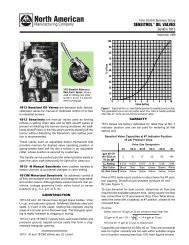
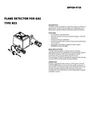
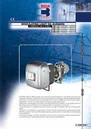
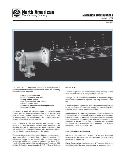
<strong>IMMERSION</strong> <strong>TUBE</strong> <strong>BURNERS</strong>Bulletin 4762July 20004762 HI-CAPACITY Immersion Tube Gas Burners give unsurpassedperformance in applications where liquids are heated bydirect-fired tubes. Features:ü very high heat releases.ü quieter, sealed-in operation.ü easily lighted flames.ü stability over wide ratio ranges.ü reliable premix pilot.ü provision for optional flame supervision.ü observation port.Large tanks of liquids are commonly heated by immersion tubesthrough which burners fire. Flames and flue products scrub insidetube surfaces, rapidly releasing heat to the liquid. Thisarrangement provides more efficient and economical heating thanremote, separately-fired heat sources.4762 Burners allow high heat releases within confined tubes --higher firing rates in smaller diameter tubes than previouslypossible, resulting in lower tube costs and smaller tanks. Theyare sealed-in for full control of air/gas ratio and to permit firinginto high backpressure. No refractory tile is used.Flames are extremely stable and quiet burning, operating over awide range of air/gas ratios. Burners include a primary airadjustment to correct for unusual tube conditions, and anobservation port for easy viewing of pilot and main flame. 4762-4 and -6 Burners have a built-in gas adjustment. A separate 1807Limiting Orifice Gas Valve is used with -7-A, -7-B, and -8 sizes.OPERATIONAccurate air/gas ratio can be obtained by using metering orificesin air and fuel lines, or by analysis of flue products.Although 4762 Burners have wide turndown with normal air/gasratios, additional turndown is possible by using excess air at lowfire.<strong>Control</strong>: High-low, high-low-off, modulating or modulating-off (noton-off) control can be used. Easy lighting and smooth operationgive safe operation with minimum attention.Pressure Drop in Tubes. High heat releases in small diametertubes require careful calculation of pressure drops within the tubesto ensure satisfactory operation. Adequate air and gas pressuresmust be available. <strong>Engineering</strong> and application information arepresented in Tables I, II, III, and IV, together with a samplecalculation to illustrate equipment selection. For specialconditions, consult North American.PILOTS/FLAME SUPERVISIONA 4021-12 Pilot Tip and 4031 Mixer should be used. A manuallylit pilot is not recommended. Pilot regulator must be crossconnectedto pilot air line.Flame Supervision: Use flame rod or UV detector. Flame rodshould extend 4" beyond outer surface of mounting boss.
SAMPLE SELECTION PROCEDUREInformation Required to Select Equipment:Heat transfer rate to liquid, load and losses*--for example, 550 000Btu/hr.Available tank space--for example, enough for 25' of tube with4 mitered elbows.Fuel--for example, natural gas.Step 1--Effective Tube Length for Heat Transfer. Each elbow orreturn bend adds 1.1' of effective heat transfer length to the totalcenterline length (including bends); soTotal Effective Length = 25' + (4 × 1.1')= 25' + 4.4' = 29.4'Step 2--Firing Rate. At 550 000 Btu/hr in Table I, the next smallesttube length is 28'.This tube length and heat transfer rate result in a required firingrate of 786 000 Btu/hr and 70% tube efficiency.ƒ (From Table I.)Then only 28' – 4.4' = 23.6' of tube is needed.Step 3--Burner Size, Tube Diameter. Remembering that the blowerwill have to supply some extra pressure to overcome tube backpressure, use Table II and the square root law of flow to select aburner with 786 000 Btu/hr or more capacity, such as:4762-4 Burner with 12.7 osi air pressure drop across the burner.From Table II, this burner requires a 4" tube.Step 4--Equivalent Tube Length for Pressure Drop. From TableIII, find that each 4" mitered elbow produces a pressure dropequivalent to 20' of straight 4" pipe.Equivalent length of tube =23.6' + (4 elbows × 20') = 23.6 + 80 = 103.6'Step 5--Air Pressure. From Table IV, at 70% efficiency (from Step2), read an air pressure factor of 0.017.Tube back pressure =0.017 × 12.7 osi × 103.6/10 = 2.28 osi.The required air pressure at the burner is then:Burner air pressure = 12.7 + 2.28 = 14.98 osi.Step 6--Gas Pressure. From Table IV, read a natural gas pressurefactor of 0.19. The gas pressure drop across the burner is then:Gas pressure drop = 0.19 × 12.7 = 2.42 osi.Adding the tube backpressure,Burner gas pressure = 2.42 + 2.28 = 4.70 osi.*Losses from vats may be substantial. See pages 125-126, Volume I of the North American Combustion Handbook.Table I. Effective Tube Lengths and Firing RatesWhen Heating 180 F Water(Note: "Effective" Tube Lengths relate to heat transfer; "Equivalent"Lengths--Table III--apply to pressure drop.)Heat Transfer,1000's Btu/hrEffectiveTube LengthFiring Rate,1000's Btu/hrEffectiveTube LengthFiring Rate,1000's Btu/hrEffectiveTube LengthFiring Rate,1000's Btu/hrEffectiveTube LengthFiring Rate,1000's Btu/hrEffectiveTube LengthFiring Rate,1000's Btu/hr300 13' 500 16' 461 21' 428 − − − −350 14' 583 18' 538 22' 500 29' 466 37' 437400 15' 666 19' 615 24' 571 31' 533 40' 500450 16' 750 20' 692 25' 642 33' 600 42' 562500 17' 833 21' 769 27' 715 35' 667 45' 625550 18' 916 22' 846 28' 786 36' 733 47' 688600 19' 1000 23' 922 29' 856 38' 800 49' 750700 20' 1170 25' 1080 32' 1000 41' 934 53' 875800 21' 1330 26' 1230 34' 1140 43' 1070 56' 1000900 22' 1500 28' 1380 36' 1290 46' 1200 60' 11201000 23' 1670 30' 1540 38' 1430 49' 1330 63' 12501200 25' 2000 32' 1850 42' 1725 53' 1600 69' 15001400 27' 2330 35' 2150 45' 2000 58' 1870 75' 17501600 29' 2670 37' 2460 48' 2280 62' 2130 80' 20001800 31' 3000 40' 2770 51' 2570 65' 2400 85' 22502000 33' 3330 42' 3070 54' 2960 69' 2660 89' 25002200 34' 3670 44' 3380 56' 3140 72' 2940 93' 27502400 36' 4000 46' 3690 59' 3430 76' 3200 98' 30002600 − − 48' 4000 61' 3710 79' 3460 102' 32502800 − − − − 63' 4000 82' 3730 105' 35003000 − − − − 65' 4280 85' 4000 108' 37503200 − − − − − − − − 112' 40003400 − − − − − − − − 116' 425060% 65% 70% 75% 80%EFFICIENCYƒ EFFICIENCYƒ EFFICIENCYƒ EFFICIENCYƒ EFFICIENCYƒ Multiply air pressure factor by burner air pressure to obtain pressure drop ineach 10 feet equivalent length of tube.‚ Multiply natural gas factor by burner air pressure drop to obtain gas pressuredrop across burner. Add tube backpressure to get required gas pressure.Consult North American for other gases. These factors are based on theprimary air setting as shipped. They will be proportionally higher if the percentprimary air is increased.ƒ "% tube efficiency" is really % available heat, which is the best possible fuelefficiency (with no wall or surface losses).Table II. Burner Capacities, in scfh airMultiply by 100 to obtain Btu/hrBurner Air pressure drop across burner, osi TubeNo. 1 5 6 8 12 16 Size4762-4 2 120 4 750 5 210 6 240 7 640 8 500 4"4762-6 4 570 10 200 11 200 12 700 15 500 18 300 6"4762-7-A 5 250 11 700 12 800 14 800 18 200 21 000 8"4762-7-B 8 000 17 900 19 600 22 600 27 700 32 000 8"4762-8 10 500 23 500 25 700 29 700 36 300 42 000 8"Table III. Equivalent Lengths of Fittings(welded), for pressure drop calculations„Mitered Short Sweep Long SweepPipe 90° 180° 90° 180° 90° 180°Size Elbow Bend Elbow Bend Elbow Bend4" 20' 35' 5' 8' 4' 6'6" 30' 50' 8' 12' 6' 8'8" 40' 60' 11' 14' 8' 10'„ Do not use this table for heat transfer calculations.Table IV. Air and Gas Pressure FactorsAir Pressure FactorsNatl. GasBurner Tube Tube Efficiency PressureNo. Size 60% 65% 70% 75% 80% Factors‚4762-4 4" 0.022 0.020 0.017 0.015 0.013 0.194762-6 6" 0.012 0.011 0.010 0.008 0.007 0.154762-7-A 8" 0.004 0.004 0.004 0.003 0.003 0.084762-7-B 8" 0.010 0.008 0.008 0.007 0.006 0.114762-8 8" 0.013 0.012 0.011 0.008 0.008 0.20Bulletin 4762 Page 2
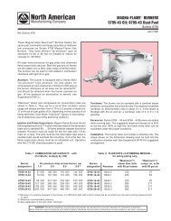
INSTALLATION1. Bolt the burner flange to a matching flange welded to theimmersion tube. Bolt these together tightly to prevent flue gasleakage. Leakage can cause instability and excessive noiseunder some conditions. (An optional mounting gasket isoffered--see Parts List & Instr. 4762-1.) The burner should beas close as possible to the tank, because heat is releasedvery close to the burner. Tank insulation, if any, should beremoved to provide clearance around the tube to preventoverheating.2. Connect the main gas regulator and valves, the pilot accessories,and a spark-ignited pilot as shown in the typical pipingdiagram below. A separate regulator must be used for eachburner. For 4762-7-A, -7-B, and -8 Burners, add an 1807Limiting Orifice Valve in the gas line as close as possible tothe burner.3. If the gas pressure does not exceed air pressure by at least2 osi, use an 8654 Bleeder, piping the "M" connection to thehole provided for that purpose in the burner mounting plate.(Subtract the tube backpressure from both the gas and airpressure before figuring the % bleed.)4. It is often difficult to set the air/fuel ratio by sight or sound; souse of a metering orifice or flue gas analyzer is stronglyrecommended.Pipe or TubeFlange or Tank WallFig. 1. Typical Piping Arrangement−Plan View(Safety equipment not shown)Pilot Mixer4 Studs (see table)GasketPilot TipKPilot GasValvePilot Regulator Cross ConnectionAIRPilot Regulator Pilot Air ValveMain Air<strong>Control</strong>ValveAirImpulseBurnerFlame Rod Opening(2 psi max.)Main Gas ValveAir/Gas RatioRegulatorMeteringOrifice(Optional)Table V. Installation DimensionsBurner Tube Stud StudDesignation Size Diameter Length K4762-4 4" 5/ 8" 1 1 / 2" 1/ 8"4762-6 6" 5/ 8" 1 1 / 2" 1/ 8"4762-7-A, -7-B, -8 8" 3/ 4" 1 3 / 4" 1/ 4"START-UP and ADJUSTMENTWARNING: Startup and adjustment of combustion equipment should only be done by trained personnel familiar with combustion technology, combustionequipment, and with the particular burner system, equipment, and controls.1. Purge the gas supply line.2. Close all gas valves.3. Set the main air control valve for about 2 osi pressure at theburner or about 1 / 4 open.4. Open the pilot air valve. Energize the ignition transformer andopen the pilot gas valve. The pilot should light in a fewseconds. (See Pilot Bulletin.)5. Remove the protective cap, and open the limiting orifice gasvalve (built into the back of 4762-4 and -6 Burners, separateon larger sizes) a few turns counterclockwise from the closedposition. Open the main gas valve. If no main flame appearsin 10 seconds, close the main gas valve and allow a fewminutes for purging before trying again.6. The flame should not start in the burner gas tube at any time.If this occurs at the low firing rate, turn the regulator’s springadjusting plug clockwise until the flame moves out of the gastube. (See Regulator Bulletin.)7. Ignition should always take place at low firing rate (2 osi orless). High fire lighting or extinguishing may accidentally putout the pilot.8. Adjust the high and low fire linkage settings (firing ratios) asdesired. These can range from 1 / 2 osi (1"wc) to 16 osi.WARNING: Situations dangerous to personnel and property can develop from incorrect operation of combustion equipment.North American urges compliance with National Safety Standards and Insurance Underwriters recommendations, and care in operation.Bulletin 4762 Page 3
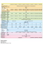
3/4 dia.–4 holeson 9 1 /2 BCIntegral LimitingOrifice Gas Valve3/4 fptfor PilotR 30°1/4 fpt fortube pressureB–fptGas Inlet45°3/4 fpt forFlameSupervision(clockwisefrom Pilot)P45°4 1 /29 sq.DIMENSIONSin inchesE4762-4 and -6A — fptMain Air Inlet3/4 fpt–2 holesfor Pilot & FlameSupervision deviceDFNfactorysettingC30°1 3 /4Gdia. Hdia.Ldia.Jprimary airadjustmentBulletin 4762Page 47/8 dia.–4 holes4 1 /84 1 /85D1 3 /4N4 1 /8EBmax.3 5 /85 1 /4 R4 1 /82 4 3 /4 R1/4 fpt fortube pressure5 Pilot 3 /4 fpt45° from flange15°10sq.Flame Supervision3/4 fpt 45°from flangeA–fptMain Air Inletfor 4762-7-A and -7-BB–fptGas InletKG dia.H dia.L dia.JA–fptMain Air Inletfor 4762-84762-7-A, -7-B, and -8FCDIMENSIONS SHOWN ARE SUBJECT TO CHANGE. PLEASE OBTAIN CERTIFIED PRINTS FROM NORTH AMERICAN MFG. CO.IF SPACE LIMITATIONS OR OTHER CONSIDERATIONS MAKE EXACT DIMENSION(S) CRITICAL.Burner dimensions in inches recommended wt,designation A B C D E F G H J K L N P R Pilot Tip lb4762-4 2 1 1 / 4 7 1 / 16 5 1 / 4 8 1 / 4 14 1 / 16 4 4 5 / 8 1/ 2 1/ 8 8 1 / 8 1 1 / 16 1 1 / 2 1 5 / 8 4021-12 464762-6 3 2 9 1 / 2 5 1 / 2 9 15 / 16 17 1 / 8 5 7 / 8 6 3 / 4 1/ 2 1/ 8 8 1 / 2 1 3 / 16 1 7 / 8 2 4021-12 464762-7-A 4 2 7 1 / 4 5 1 / 4 8 3 / 8 12 1 / 2 8 8 3 / 4 3/ 4 1/ 4 9 5 / 8 Closed — — 4021-12 544762-7-B 4 2 7 1 / 4 5 1 / 4 8 3 / 8 12 1 / 2 8 8 3 / 4 3/ 4 1/ 4 9 5 / 815/ 16 — — 4021-12 544762-8 6 2 7 1 / 4 5 1 / 4 12 12 1 / 2 8 8 3 / 4 3/ 4 1/ 4 9 5 / 8 1 3 / 8 — — 4021-12 67 1 / 4If used, flame rod length should be 4" from outer surface of mounting boss.Spray washerfiring leg must not extendmore than 3" abovenormal liquid surfacePrinted in USAcommon immersion tube arrangementsNorth American Mfg. Co., 4455 East 71st Street, Cleveland, OH 44105-5600 USA, Phone 216-271-6000, Facsimile 216-641-7852E-mail sales@namfg.com l www.namfg.comNA700-B4762