Evaluation and Repair of Wrought Iron and - Purdue e-Pubs ...
Evaluation and Repair of Wrought Iron and - Purdue e-Pubs ... Evaluation and Repair of Wrought Iron and - Purdue e-Pubs ...
from lcc.edu
More from this publisher
10.07.2015
Views
74Figure 3.31 Side View of Finished Filler Weld in Eyebar Connection B Showing HeatDistortionFigure 3.32 Eyebar Connection B Cherry Red Hot Before Being Straightened
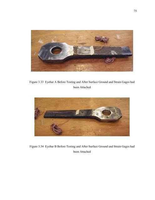
75Figure 3.33 Eyebar A Before Testing and After Surface Ground and Strain Gages hadbeen AttachedFigure 3.34 Eyebar B Before Testing and After Surface Ground and Strain Gages hadbeen Attached
- Page 44 and 45: 24Elleby, Wallace W. Sanders, F. Wa
- Page 46 and 47: 26From all the surveys that were di
- Page 48 and 49: 28Table 2.1 Average Ultimate Streng
- Page 50 and 51: 30Figure 2.3 Wrought Iron “Sponge
- Page 52 and 53: 32Histogram of Kirkaldy Wrought Iro
- Page 54 and 55: 34Percent Occurance in Range - %45.
- Page 56 and 57: 3660Combined Wrought Iron BarsTensi
- Page 58 and 59: 38The Bell Ford Bridge consisted of
- Page 60 and 61: 40Two. These samples were taken fro
- Page 62 and 63: 42specimens were of constant cross
- Page 64 and 65: 44Along with rectangular tensile co
- Page 66 and 67: 46After the initial test loading wa
- Page 68 and 69: 483.6 Fatigue TestingTo develop a b
- Page 70 and 71: 50The final specimen category consi
- Page 72 and 73: 52This analysis was completed using
- Page 74 and 75: 54After the initial test was comple
- Page 76 and 77: 56completed, but before the surface
- Page 78 and 79: 58readings, load cell readings and
- Page 80 and 81: 60Figure 3.3 Donated Eyebars 4 and
- Page 82 and 83: 62Figure 3.7 Heated Areas in Blue o
- Page 84 and 85: 64Figure 3.11 Detail Used in Groove
- Page 86 and 87: 66900080007000y = 27.153xR 2 = 0.99
- Page 88 and 89: 68Figure 3.19 Charpy Impact Testing
- Page 90 and 91: 70Figure 3.23 Eyebar Connection in
- Page 92 and 93: 72Figure 3.27 Eyebar A After Filler
- Page 96 and 97: 76Figure 3.35 Front View of Eyebar
- Page 98 and 99: 78strength from the existence of pe
- Page 100 and 101: 80The carbon content present in the
- Page 102 and 103: 82value may not be very accurate bu
- Page 104 and 105: 84strengths was found to be 29,940
- Page 106 and 107: 86wrought iron bars were investigat
- Page 108 and 109: 88stresses are induced. These perma
- Page 110 and 111: 90toughness the material. The test
- Page 112 and 113: 92From the finite element analysis,
- Page 114 and 115: 94Table 4.1 Chemical Analysis of Ey
- Page 116 and 117: 96Table 4.3 Tensile Coupon Test Res
- Page 118 and 119: 98Table 4.5 Charpy Impact Test Resu
- Page 120 and 121: 100Table 4.7 Comparison of Strain G
- Page 122 and 123: 102Figure 4.1 Typical Micrograph of
- Page 124 and 125: 104Figure 4.5 Fracture Surface of D
- Page 126 and 127: 106Comparison of Tensile Strengthfo
- Page 128 and 129: 108Combined Wrought Iron Bar Histor
- Page 130 and 131: 110Figure 4.17 Macrograph of Weld u
- Page 132 and 133: 112Figure 4.21 Cleavage Fracture of
- Page 134 and 135: Figure 4.25 Elongation of Hole in E
- Page 136 and 137: 116signs on or near the bridge that
- Page 138 and 139: 118testing of historic wrought iron
- Page 140 and 141: 120so that they would act in symmet
- Page 142 and 143: 122The reasons for the differences
75Figure 3.33 Eyebar A Before Testing <strong>and</strong> After Surface Ground <strong>and</strong> Strain Gages hadbeen AttachedFigure 3.34 Eyebar B Before Testing <strong>and</strong> After Surface Ground <strong>and</strong> Strain Gages hadbeen Attached


